Indeed, the twists and turns in the thoughts that go through our minds at the bench ![]()
![]()
1 Like
Looks amazing.
Even without the, much sought after, assistant, you managed to align the parts beautifully.
Thanks Jesper.
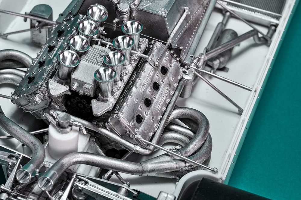
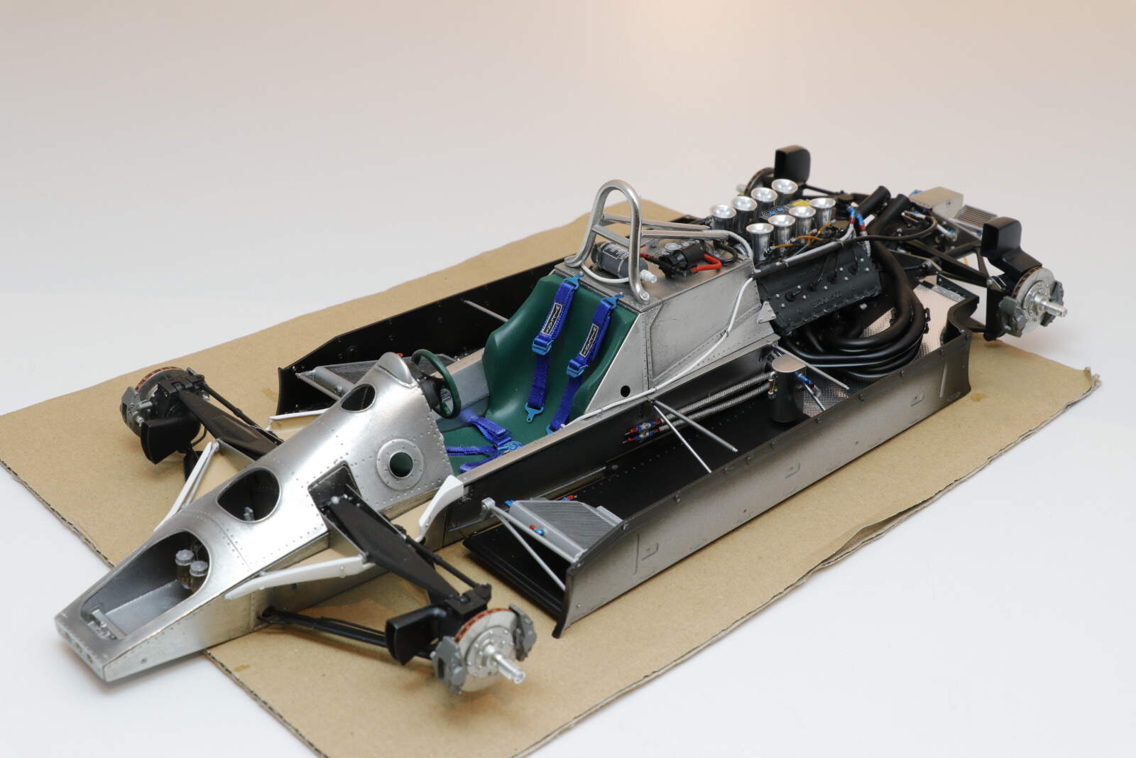
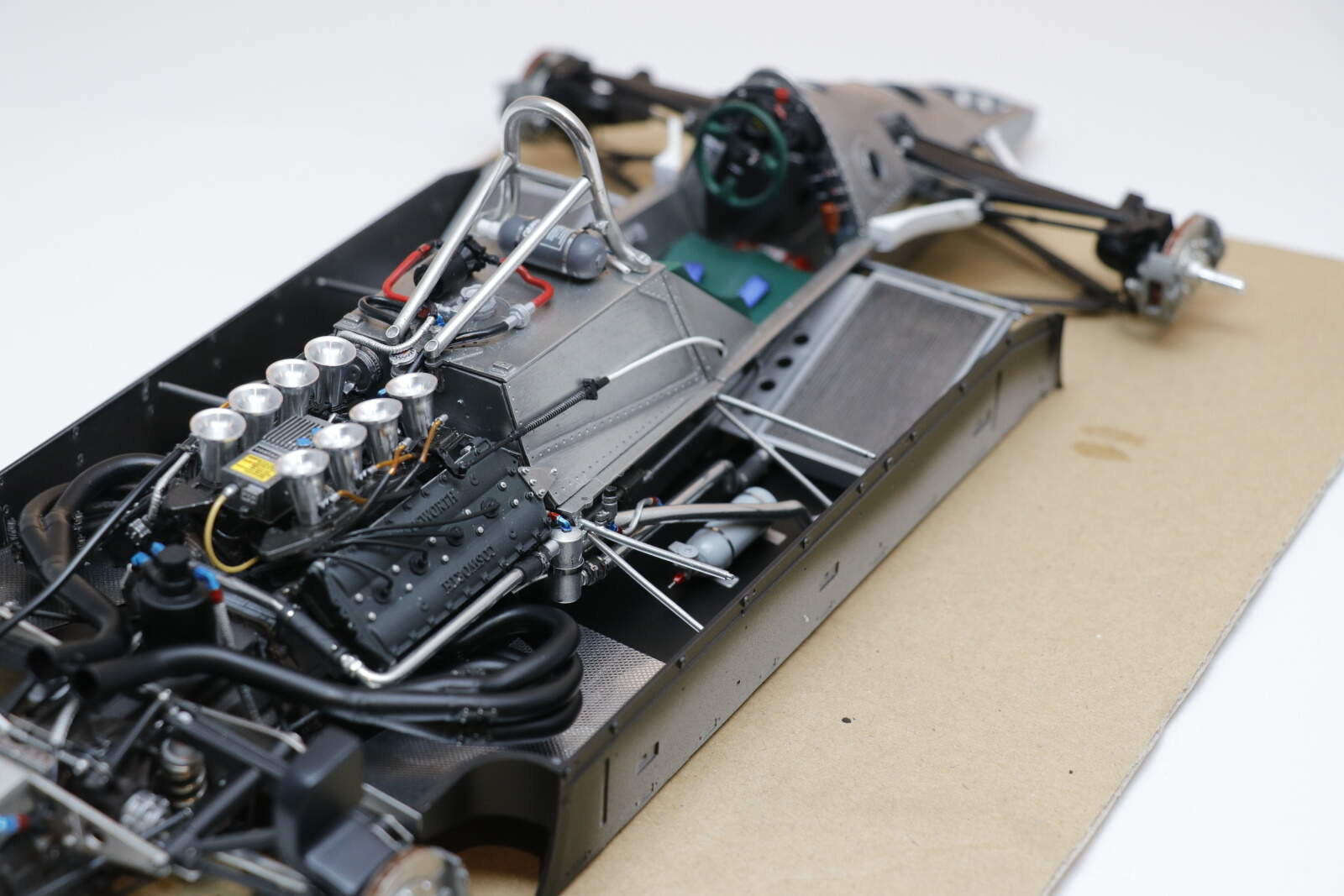
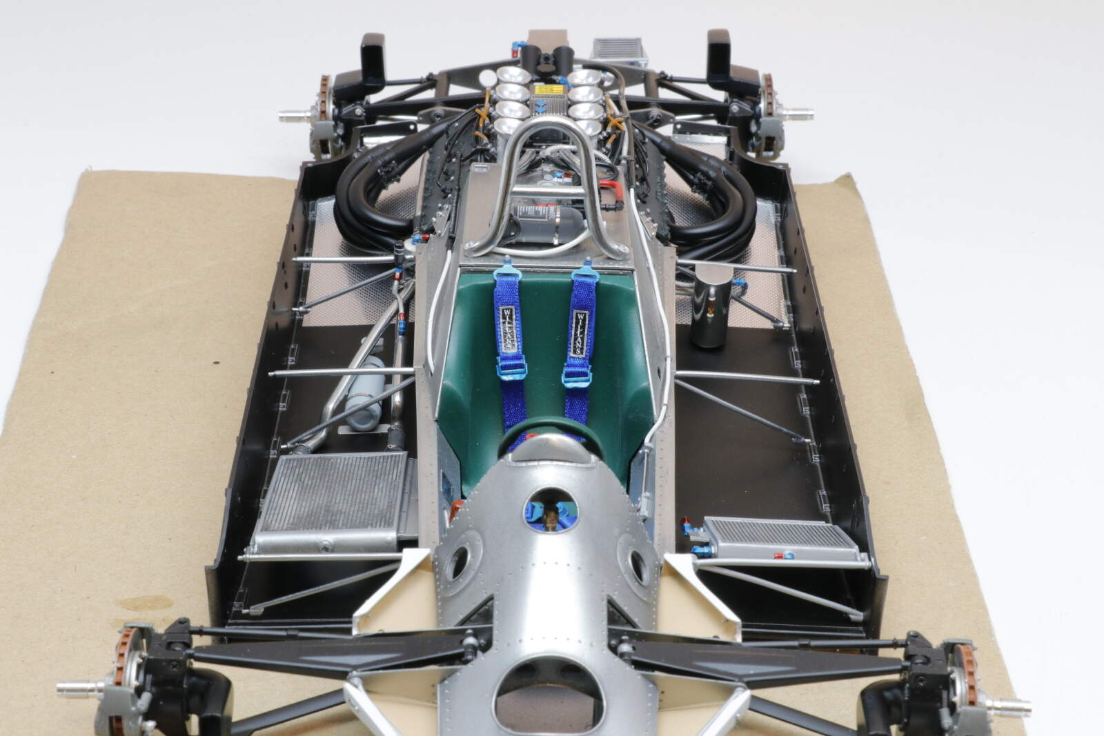
here we have the right hand side for radiator and pipework and body hangers. You can also see the gear change mechanism running down the side of the chassis. The throttle linkage sits on the side of the fuel tank, still to be linked to the loud pedal.
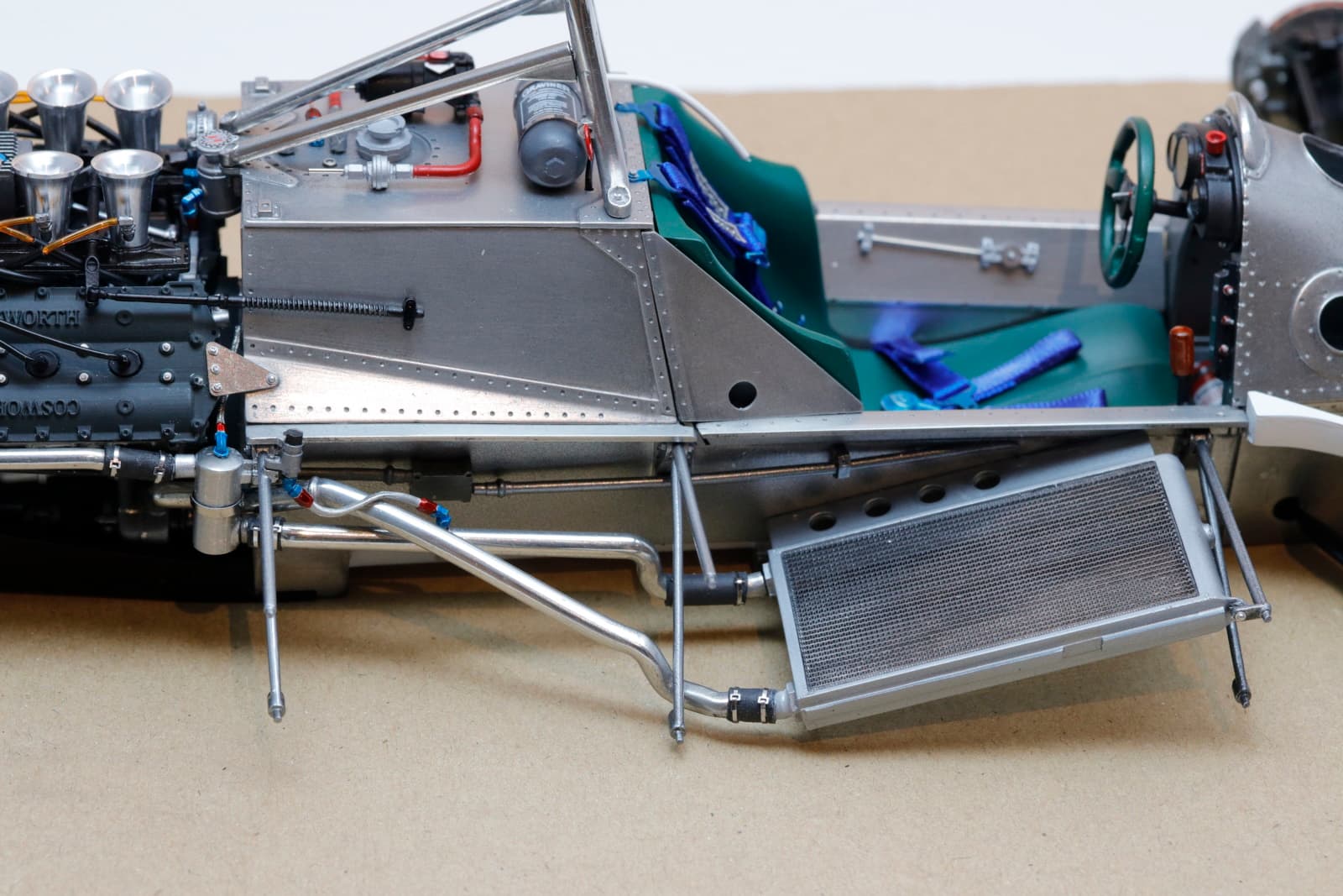
and from the rear view
cheers
Michael
7 Likes
Michael,
Absolutely impressive detail work. It’s getting harder and harder to distinguish between what’s the real car and your build. Your choice of various metallizers really is paying off.
Just something that kind of jumped out at me since our discussion about to add rivets or not to add rivets, in the pictures, especially the 1st side view, all the rivet dimples due to the lighting don’t look like depressions, but rather like there’s a rivet head in each one. I’m sure that up close and personal it looks different, but that’s how I see them in your pictures.
joel
1 Like
Very impressive Michael. I wonder why MFH didn’t cast the rivets in - to make more $$ by selling the rivets separately perhaps ? Anyway, like Joel said, it looks fine as is .
Richard,
What you said makes a whole lot of sense, as anything to squeeze a few more bucks out of us already broke modelers.
So how’s the bike progressing these days?
joel
I’ve been looking, at the images, over and over again; so many details to take in. Amazing.
1 Like
Thanks Jesper, that’s mainly down to MFH and some patience on my side!
cheers
MIchael
It’s a fact, I hate plumbing.
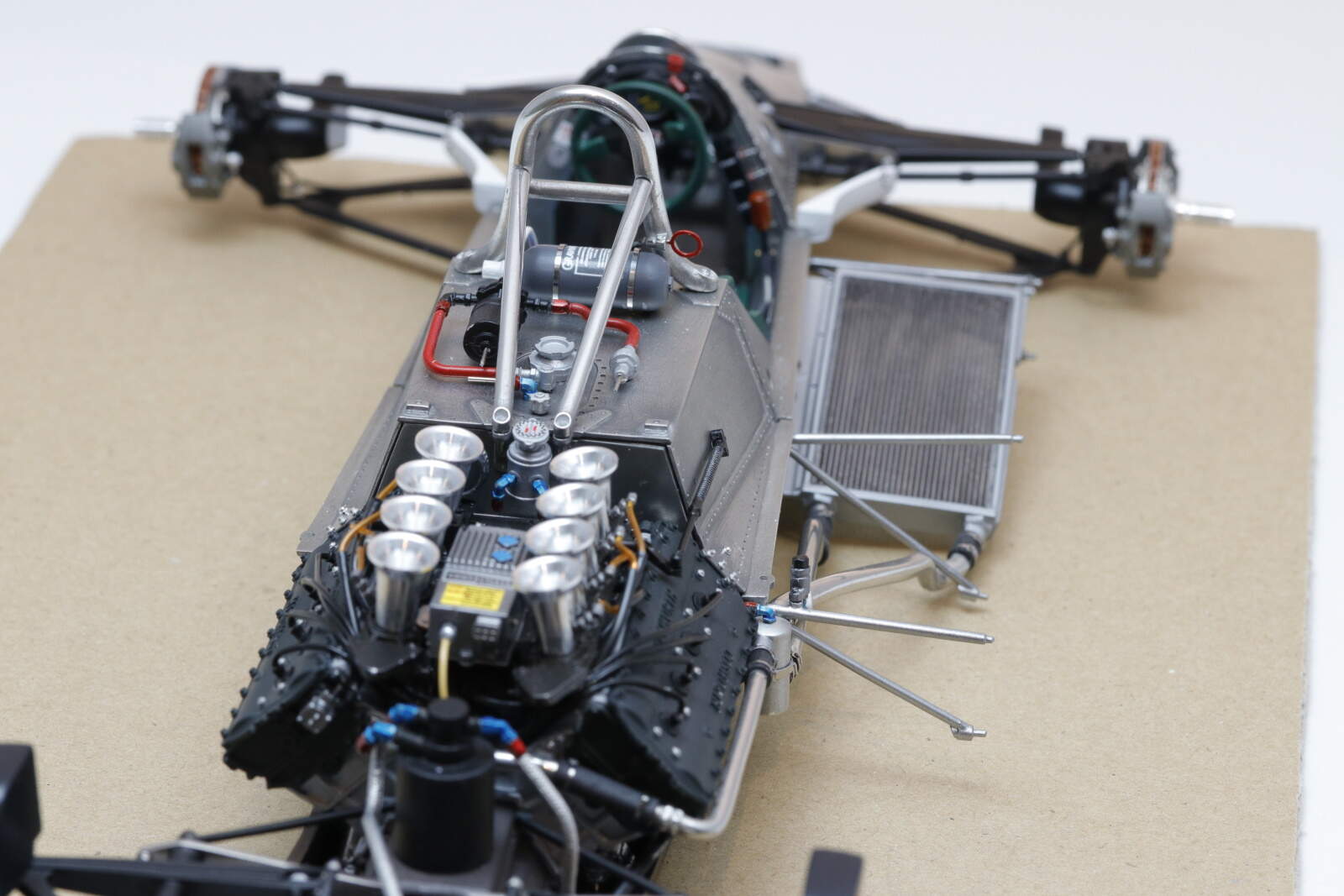
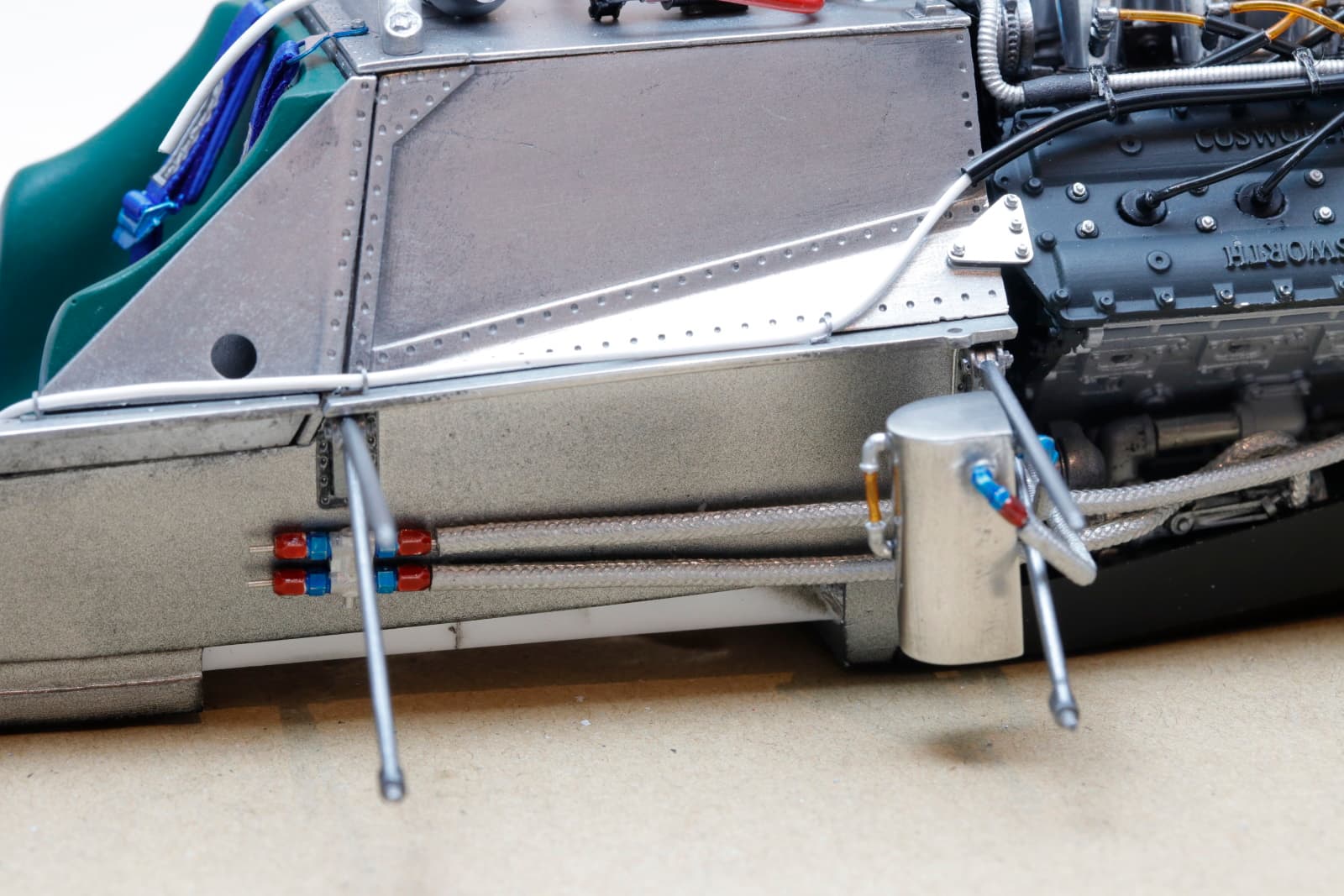
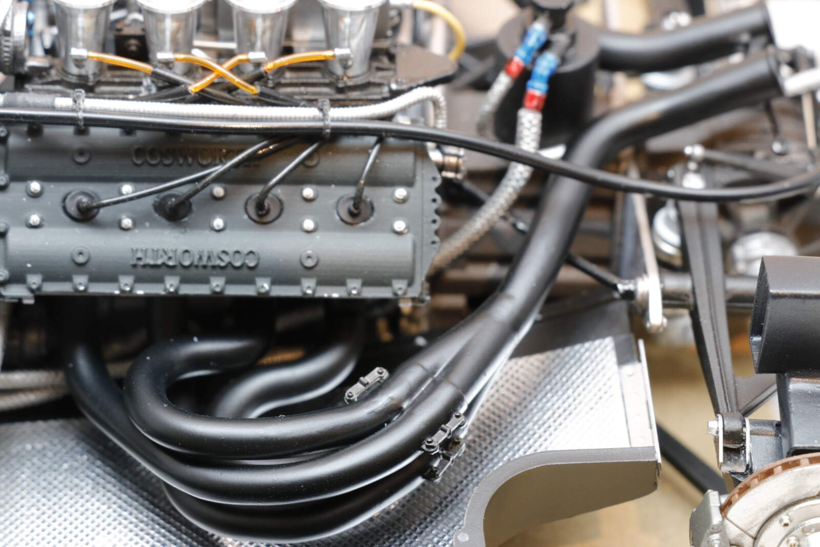
Onto the left hand side now. A few drawbacks here with the MFH kit. First the indicative pipe routing is a bit dodgy in the instructions and second, the metal braided pipes are very stiff and act like rasps on any of the paint work. Here’s the big picture view
The white cable above running into the black tube is linked to the rollbar adjuster in the cockpit.
The first sets of pipes were from the top of the fuel tank. The metal one here broke but I rejoined it and covered with some heat shrink tubing, while may be not authentic, it hid the join.
The radiator on the left side is attached to the floor rather than the chassis so that will wait until the flooring is in place but the tubing is in place. Again stiff metal pipes. The challenge here, and it took some trial and error was to make sure they don’t interfere with the exhausts. It is all a tight fit and required several fittings (and no little amount of cursing) to get a final fit.
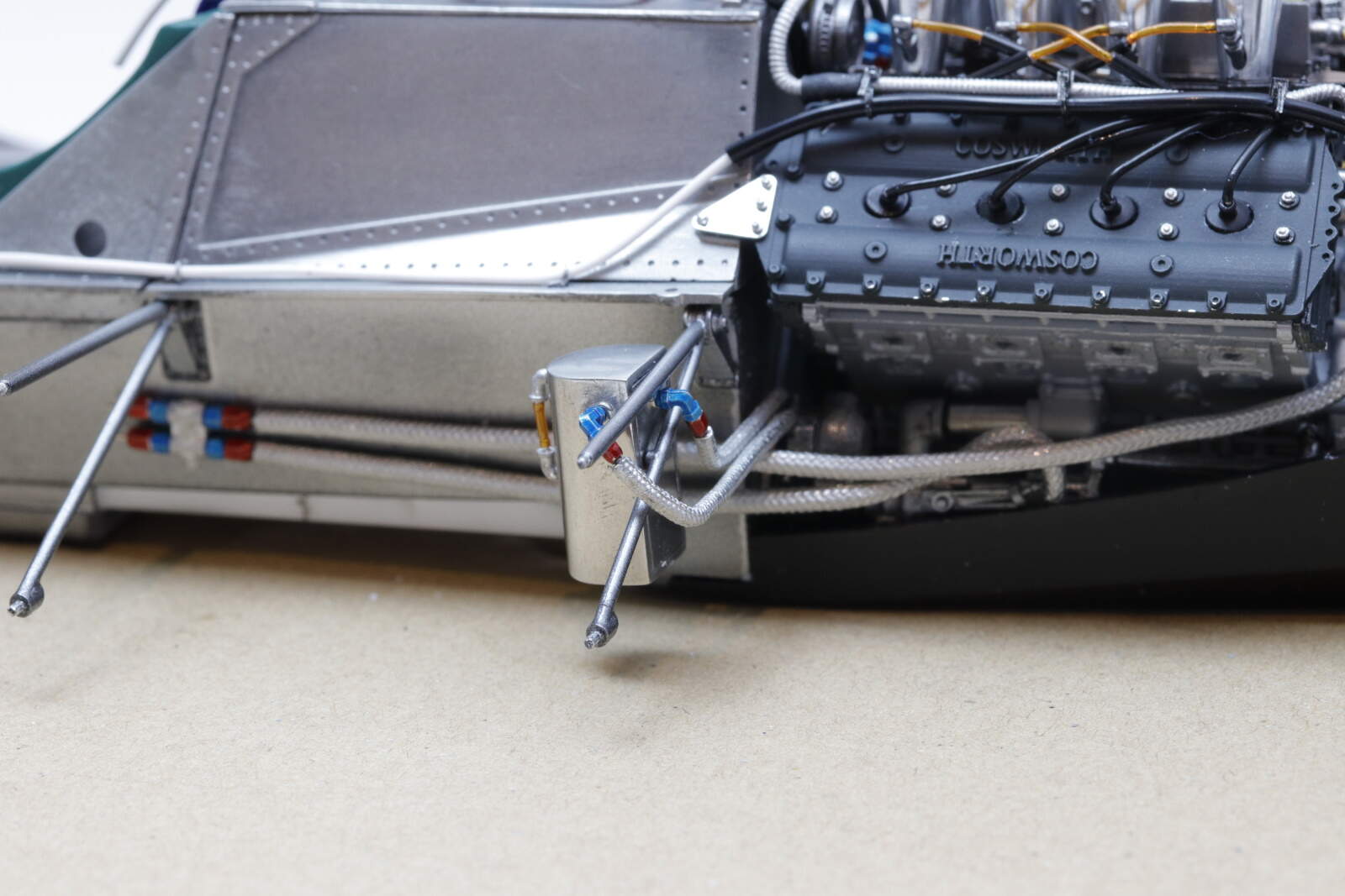
The exhausts are up next. Just dry fitting around existing fixtures and fittings tells me they’re going to challenging. I guess everything was tightly packed within the body work to keep the aero flow clean. Must have been a nightmare to work on.
cheers
Michael
6 Likes
As always a joy to view your work Michael. Modeling vicariously through you and others at the moment as my own project is stalled due to life but I’ll be back at it soon.
Michael,
it’s the end results that counts, and from the pictures you posted, the build is coming out plumbed just like the real car.
As you said, everything is plumbed at tight as possible so that the body work is narrower and cleaner, which means less drag, and a faster car.
Richard, glad to hear that you’re still with us. I guess that being a Grand Pa has you pretty busy right now. Looking forward to your grand return sooner then later.
joel
@RDT1953 I was wondering what had dragged you away from the Gold Star, hope it is nothing major.
@Joel_W Thanks Joel. My biggest worry now is about the bodywork and will it fit. Once I get the exhausts done I will find out. One thing thing I know for sure, it won’t be straightforward!
cheers
Michael
1 Like
Awesome stuff Michael, I’m just loving the fine work going on!
Cheers, D
Thanks Damian.
I am getting somewhat cranky with this kit with the two steps forward and then back.
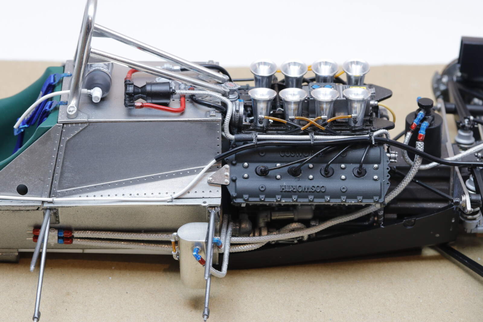
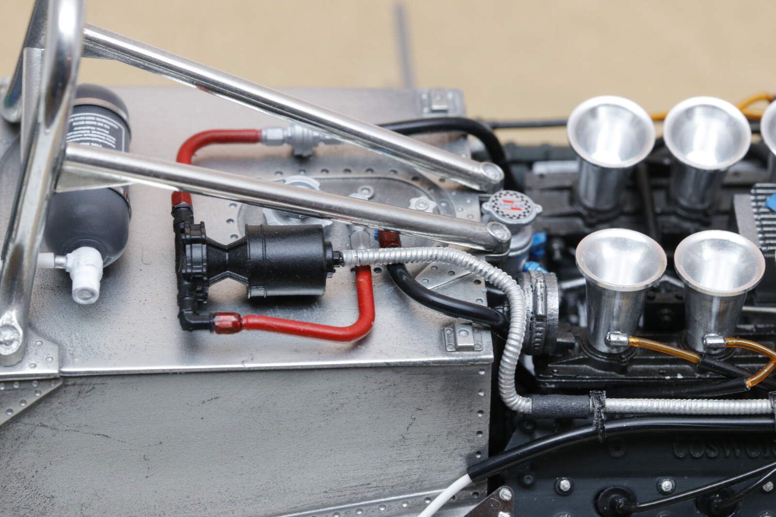
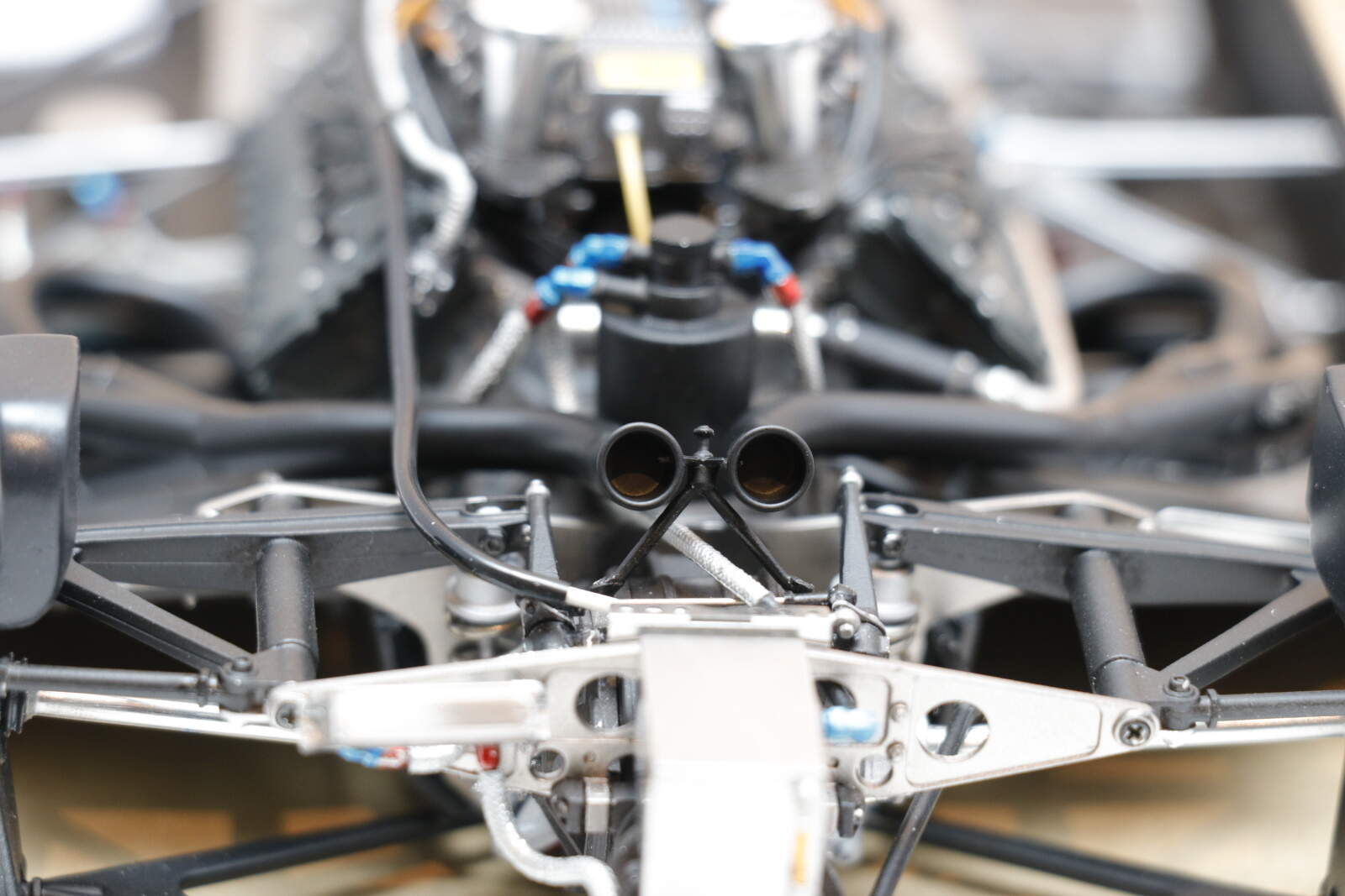
To set the scene. As you know I said the wiring diagram from MFH was a little dodgy, this is the instructions, Step 14.
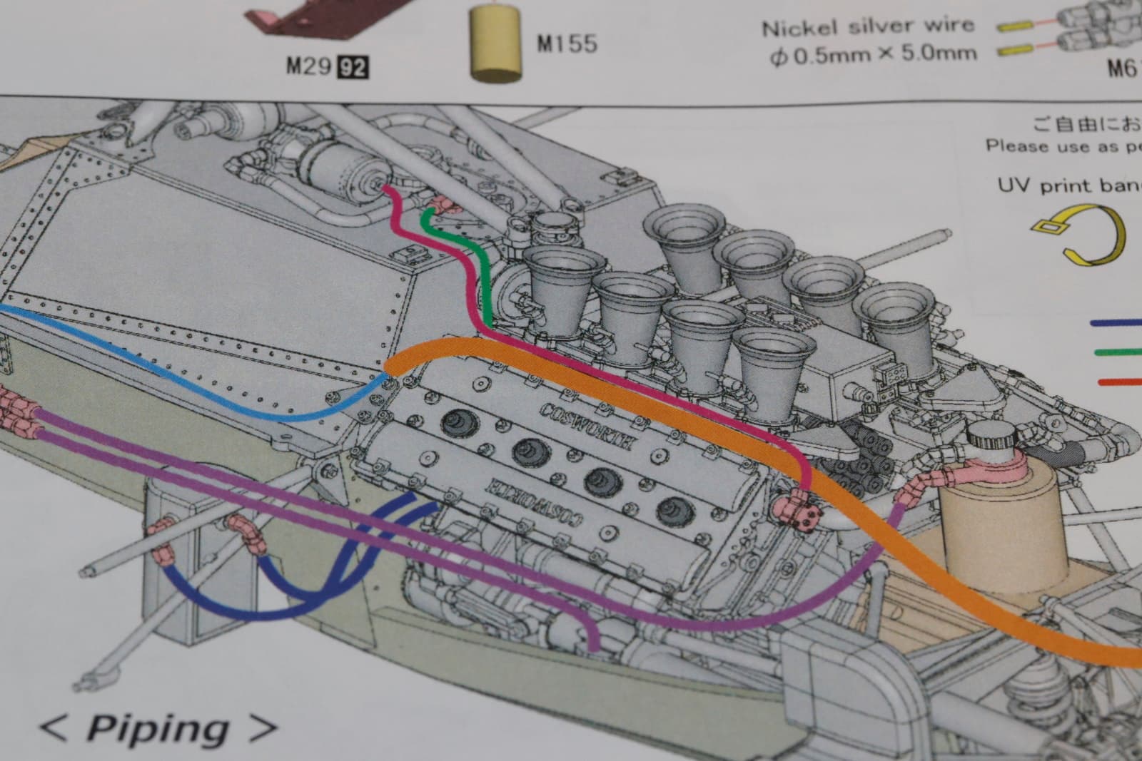
The offending items here were the purple coded lines running above the brackets right through where the exhausts go. Everything else I wired pretty much as indicated. The purple lines I ran below the bracket to gett inside and underneath the exhaust.
Step 15 fitting the exhausts
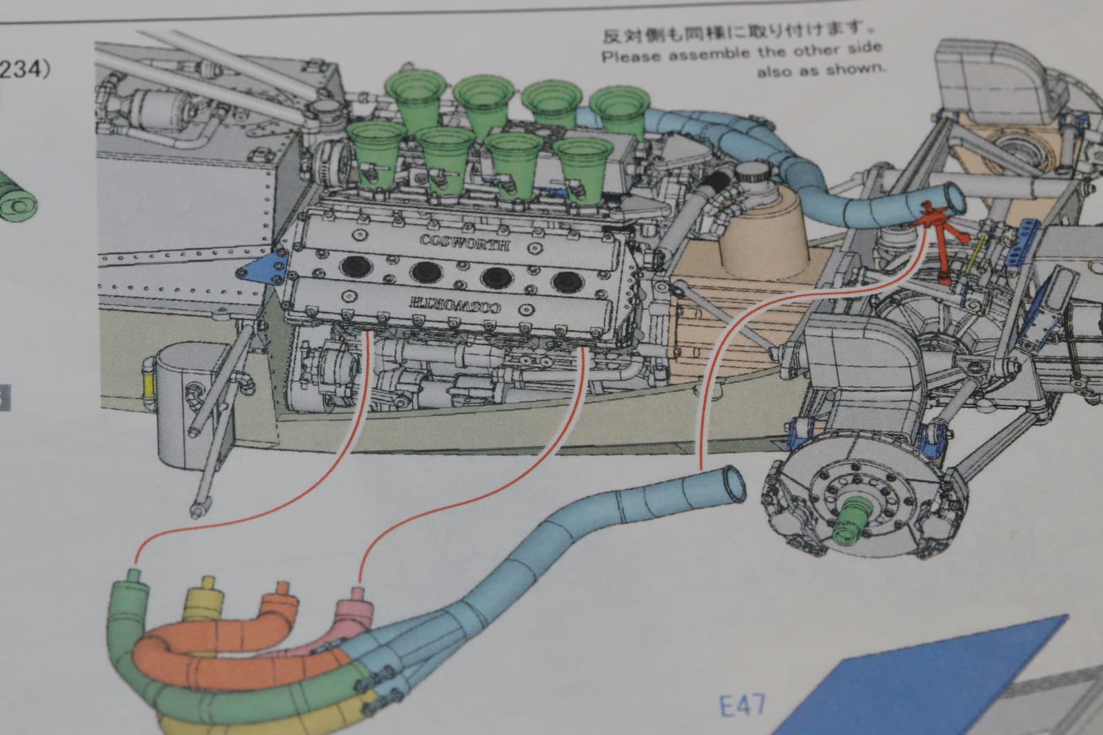
Note that there is not a pipe or wire insight to impede installation. I wonder where MFH thought they all went This is important because MFH show built up versions of all their cars and bikes like this
Notice any missing in this picture of the assembled engine and exhausts - yes, no wiring or plumbing.
Why does this all matter? Back to the first picture
I did the rest of the wiring as per the instructions, the red, green and pale blue. However since MFH didn’t, what happened? The upper bodywork doesn’t fit because it sits flush to the chassis, especially at the back to the top of the fuel tank where I have run the pipes and down the side where the pale blue sits. It all has to be re-organised, something I am still figuring out for where it will go.
This is why I am cranky that MFH ignored the fact that the tubes are 1.5 to 2 mm thick and they didn’t test it out on their build. I’ll get over it I’m sure but for the moment…
cheers
Michael
4 Likes
Yet more evidence to illustrate the fact that these kits are not for the faint of heart - I’m sure you’ll get it right though Michael. I feel your pain regarding doing over.
I tell my carpentry clients once they have decided on something - “ If I do it twice it’s four times the price “
Cheers- Richard
1 Like
Michael,
I have complete confidence in your abilities to figure out the correct routing.
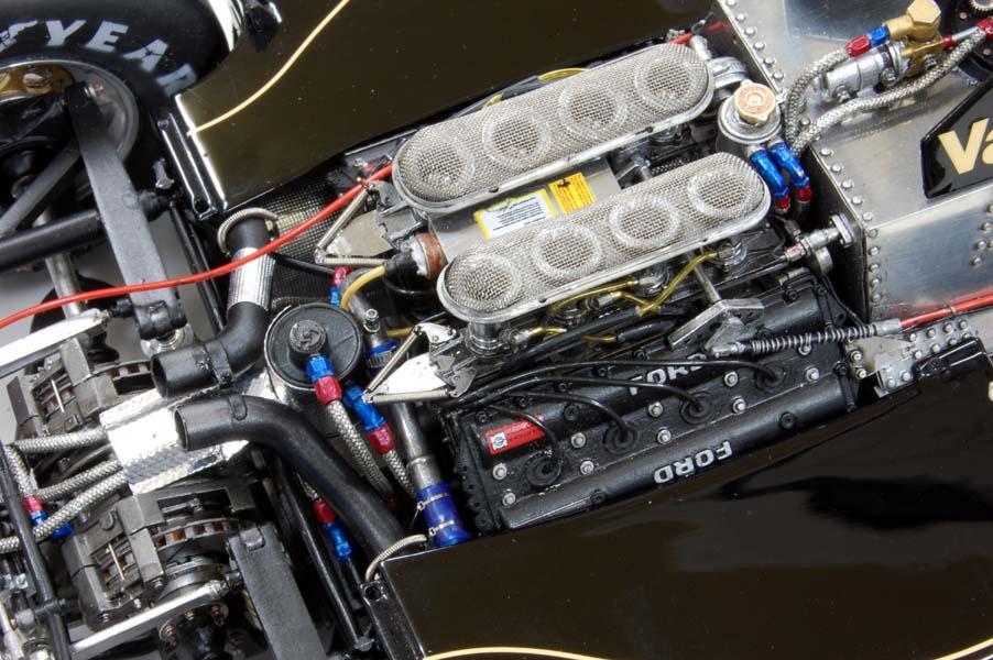
I had the same issues with the Lotus 99t and 97 that every wire, and line I ran across the gas tank became an issue as the body also fit super snug against the tank sides. But in reality the body didn’t fit that snug, and those lines do fit.
As for the purple lines, your routing them between the body bracket and under the exhaust header is how they were routed in the 1978 & 1979 Lotus type 79 which had the same basic chassis/engine layout.
Joel
Ha, unfortunately I don’t have anyone to pay me for this ![]()
@Joel_W Your second photo has given me an idea to explore.
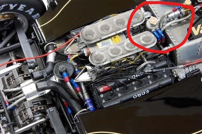
I will see if I can some room down there.
cheers
Michael
Michael,
Glad that I could be of some help.
joel
So I finally stopped sulking about MFH’s instructions and got back to it.
Change the plumbing to go between the roll bars. a bit messy since I didn’t have too much spare to put new cables in.

Then the exhausts which were an exercise in patience, knocked a few things off, scratched some paint wrestling these into position.
The two sides come together to fit in a narrow vent in the rear bodywork.
And I have been working on the sidepods - left hand from the front - they’re just sitting in place at the moment
right side - you can see the heat shielding under the exhausts
and from the front - you can see multiple attachment points - it is pretty tricky to get everything lined up
The sides of the pods are unpainted because that is where the skirts go before the outer bodywork panel is attached. Of course the skirts move up and down!
cheers
Michael
7 Likes