MikeyBugs 3D Design and Printing Ideas

I knew it! :smiley: Looking forward to seeing what you can come up with it.

1 Like

it looks great; stick one of those behind the SINCGARs on a Humvee or on the weapon’s Station. for added realism.

3 Likes

So far it’s been a good learning experience. I worked in a dental lab for all of a week a few years ago on their dental scanners so I have some previous applicable experience on the software side of things. It’s more so getting used to the scanner itself and its quirks.

Otherwise, some work on the Graflex KE-12(1) for @165thspc


1 Like

Mike this is more of a CAD design question than a modeling question: Why do these images appear in some sort of reverse perspective? I understand an icometric drawing that has no perspective projection but these really look like the object is getting bigger the further away it is from the viewer.

Also when in the open position the camera box body should be completely hollow. In reality there is actually a window thru to the back.

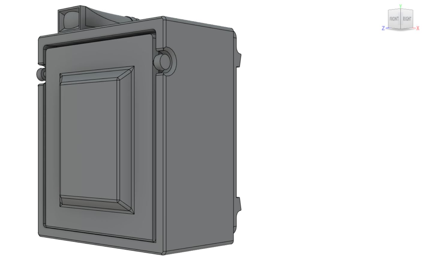
So this is an isometric view. Normally, we see an object with converging perspective lines, where all lines, if extended forever, would converge at a single point in finite space. In 3D CAD, you can switch between various “perspective” views and an isometric view. With isometric views, the true shape of an object is shown with no perspective distortion. Parallel lines are shown as parallel and don’t converge at any single point. It’s kind of similar to what happens with a long telephoto lens. As you get further from the subject, and the focal length gets longer, the foreground and background start to compress together. Isometric projection can lead to some illusions like what you pointed out. But it’s just because our brains are not used to seeing in isometric projection. We expect lines to converge at some point so when we see lines not converge, it can confuse our subconscious.

Example: here’s the perspective view. Note the view cube in the top right corner.

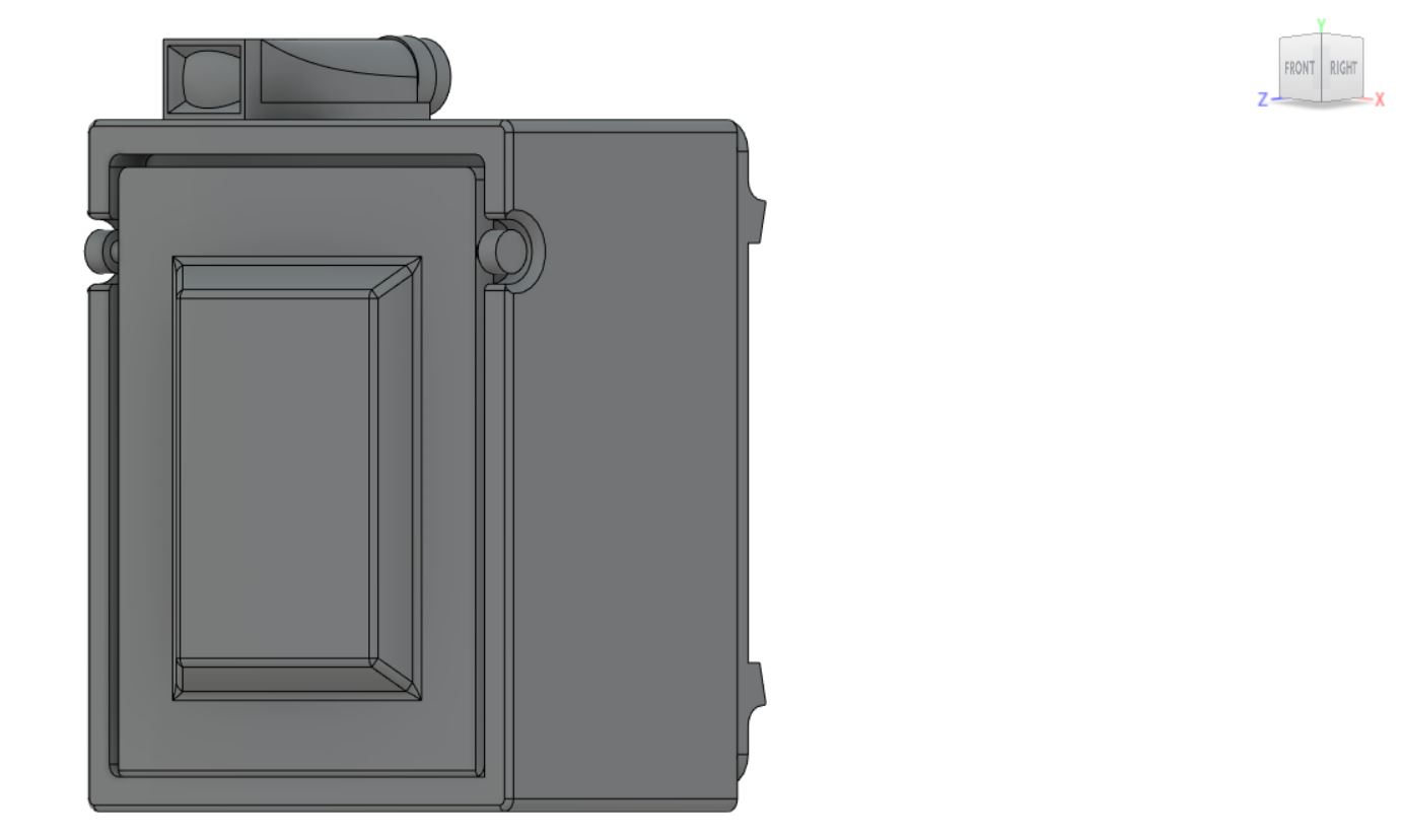
and here’s the isometric view. The view on the view cube hasn’t changed but the perspective shift is significant.

And yes, I’m working on more of the body before working on the interior of the camera body. Because of the way the printer works, when I make the bellows, I still need the camera body to be solid. I can’t have any empty voids in the model or liquid resin will accumulate in them and could prevent the model from printing successfully at best or there would be liquid resin in the model after it prints that can’t be cured at worst.

2 Likes

Well in the many years before CAD ever existed I was, for a short while a draftsman so as I said, I know what an isometric drawing is. However to my eye your CAD drawings looked almost like some sort of reverse perspective where the object was getting LARGER the further away it got.

So nice that today one can just hit a button and change from perspective view to isometric!

That reverse perspective is your brain trying to make sense of the image not tapering to a point. No matter how much we understand what’s going on, the part of our brain that processes the stereo image from our eyes still struggles. I’ve been driving CAD for over three decades now and still see things apparently tapering out as they go away…

1 Like

You are no doubt correct. Have not looked at an isometric in many MANY years

It’s not pencil to vellum anymore and it’s not spending hours in a photo darkroom anymore… Thankfully, those days are over!

To those who are designing 3D, I salute you. :saluting_face:

—mike

1 Like

I agreed! Ditto

Photo processing at my computer is way more fun than the darkroom ever was AND I have so much more control.

1 Like

OK some work done on the Graflex and an updated wood pallet. I just need to do a test print for the pallet but otherwise it will be $10.46 for a pack of 2 printed at 50 microns or $7.16 for a pack of 2 printed at 100 microns. I’ll print a test of both so everyone can have see the difference between them.

4 Likes

Back of camera looks good.

I will get you a shot of the right side of the camera body with all the focal plane shutter controls and the rangefinder. That is what will turn this Graflex into a Speed Graphic.

The focal plane shutter built into the rear of the camera provided faster shutter speeds than the in-the-lens shutter. Better for stopping fast action sports and racing photography. However the, front mount, in-the-lens shutter worked better when doing flash, or regular Press type photography.

There is a good chance the Army Combat Photographers did not even use the Speed as it was more complex, something else subject to break down and too, the in-the-lens shutter would handle 98-99% of what these guys were needing to shoot. I just wish Halloran or Joe Karr were still around to ask!


(If I were shooting the Iowa firing a salvo, or a TBM catching the arresting cable on the flight deck the Lexington I would want to be using a Speed Graphic but for sitting in a Foxhole photographing slow moving Shermans and Panzers doing battle or for regular Press coverage of Eisenhower or Patton’s arrival the more simple Graflex would be all that was needed.)

2 Likes

Mike I saw your attempt above to do a realistic modern GI helmet. Good job!

How 'bout giving us a source for a good after market WWII helmet covered in netting with the leather band across the brim and the chin straps hanging loose?

I wish I had one for the GI Combat Photographer figure I am building right now!

It’s in the plans. I just need to aquire one.

p.s. FYI ~ Even the lowly Graflex still had the rangefinder housing mounted on the right side of the camera body for precision focusing, (when time and subject allowed for it.) Otherwise you were estimating distance to subject by eye and setting your camera accordingly.

2 Likes

I can photograph my helmet but that does not help you if you are wanting to scan one.
I could ship it to you on loan if you think that is justified?

1 Like

If that works for you sure. Scanning is thankfully significantly faster than designing from scratch like what I’m doing with the LTAS for Gino. I still have a kit on loan from him to use as a base fit test. I need to finish that up before I start accruing interest on it.

1 Like

On this part, though, what I can do is model the parts for both and then only include the parts that apply to the separate models. That way they both can be available without having to redo the camera.