Wow Bruce, pooch doesn’t often get impressed but…


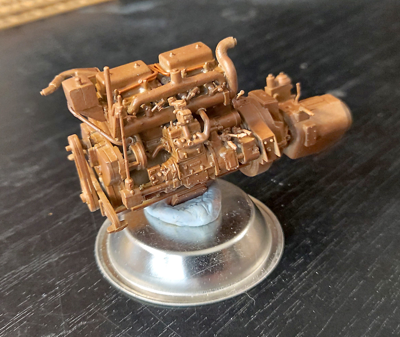
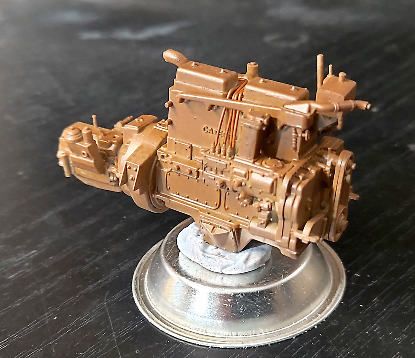
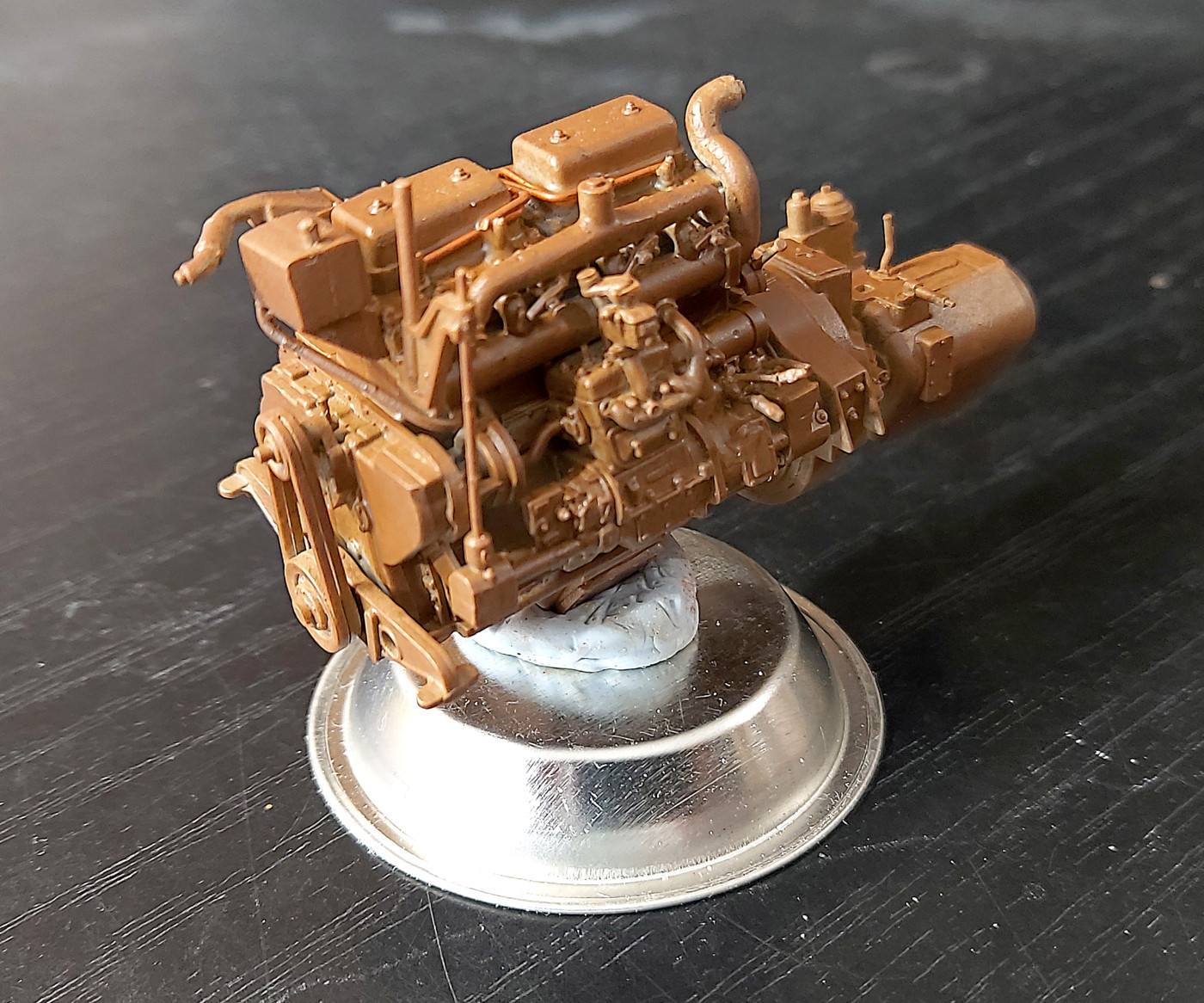
Time to lay down some paint. A light coat of Brown Oxide. (Mig Ammo). This primer dries very fast on the tip and in the gun. So I thinned it down to 50-50. It is too thin but will be ok for a hairspray layer and then the yellow. The primer refused to cover the copper injection lines. So they may get a brush coat of primer.
I can’t imagine painting the parts first. Removing paint for a good glue contact would be a nightmare.
bruce
Damn dude. That looks awesome! Keep up teh great work/photos
I bought a Miniart T-55 Polish Production. Cracked the box, saw how it was packed out with sprues, and have been scared of it ever since 
Me too Joe, I bought the T-55 with interior…. Holy cow!
I must be really crazy, I have two! Haven’t worked up the nerve to start one yet.
Ken
Bruce, that looks freakin’ awesome! Keep up the great work. Following with much interest — got a MiniArt (35188) U.S. Armoured Bulldozer in the stash.
Cheers!
—mike
It’s good I found this build - I’ve toyed with the idea of getting one of the military version but geez, those miniscule parts are not for my eyes. I have built their M3 Grant with interior, but it didn’t seemed this tedious. As it was said before, the thin levers/rods/pipes were prone to snap when cut or cleaned - better to have a set of different size Evergreen rods at hand.
Great job, thanks for sharing! (I’m envy of your patience and steady hands…  )
)
Folks keep in mind this is a later MiniArt kit. It has the ‘good’ soft plastic. I’ve broken only one piece so far. And it was my fault for rushing the job.
I’ve been ‘ok’ with tank interior kits. It’s either on the outside or inside and painting isn’t that hard. Or not as hard as I thought.  But this kit has caught me out. I don’t like scraping paint off bits to glue them. So painting sub assemblies is my preferred method. But this has stumped me with parts that need to be painted and need to be scrapped to glue. No way would I try to paint all the engine parts first. But the rest of the kit is an issue. I thought I primed all I thought I needed. But I thought wrong.
Tip for anyone doing the same kit. Assemble the engine up until the radiator. Paint and continue. Assemble the tracks and then paint. And try to paint the rest on the sprue and do touch up later. Maybe!! I’m not there yet.
Glad everyone is interested.
bruce
An update. I thought I was being clever and only primed what I thought would be visible. Nope. Out smarted my self. But I did realise that spraying sub assemblies would be smarter!! 
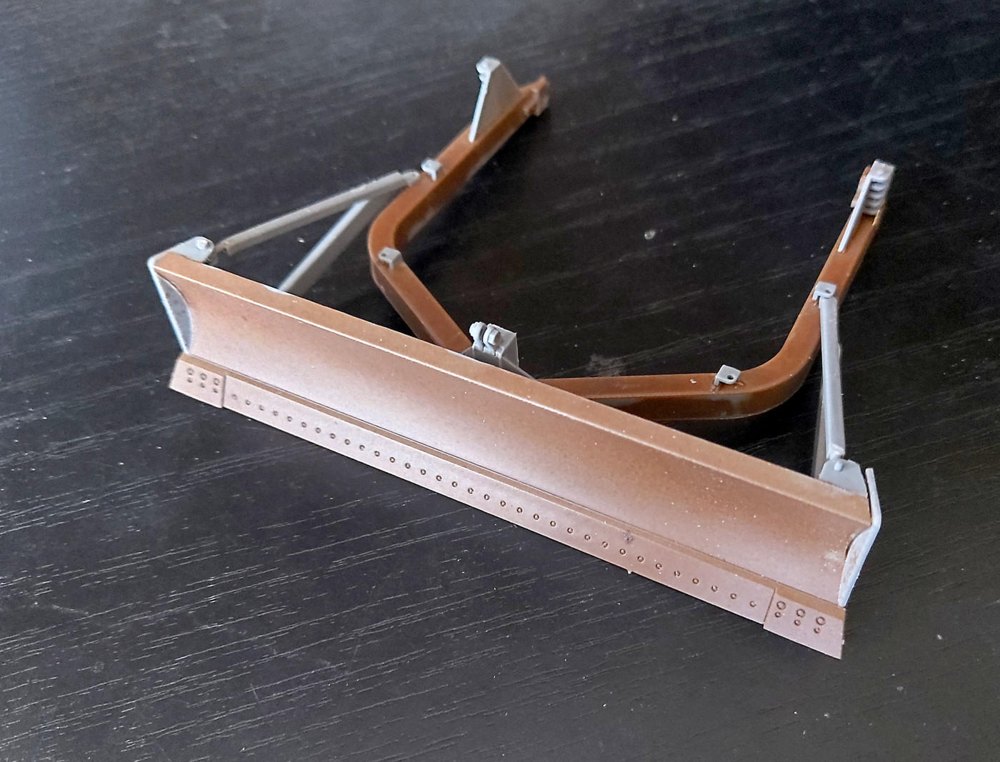
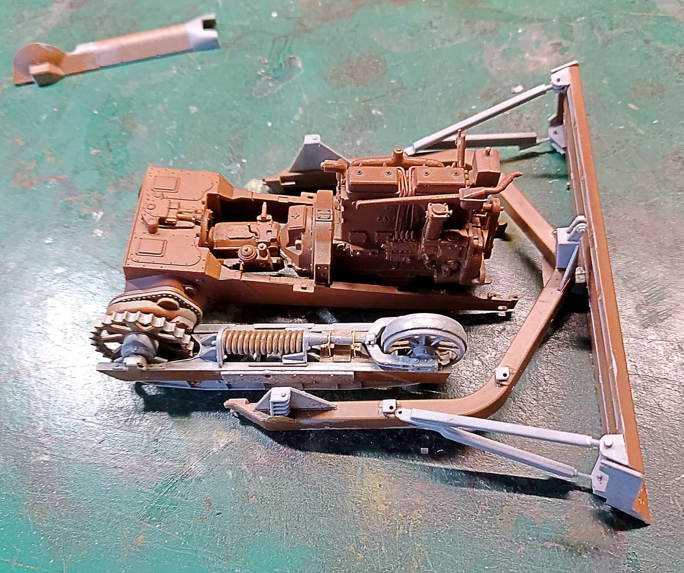
I jumped ahead to the blade and track mechanism. Anyone building this kit note that part E15 is the swivel point for the blade. If you want a working blade I suggest gluing part E15 to the bottom of the blade rather than trying to fix it between E17 and E16. Also parts De3 go outside the markings and not inside of the markings. The U shaped frame for the blade mechanism is two parts with 38 sprue gates to clean off!
There is quite a bit of guessing with the roller mechanism. Look ahead a page or two to check locations. I got mine assembled but the rollers don’t turn. Glue ‘creep’.
The top of the roller mechanism is ‘interesting’. They tell you to cut part C45. I did. Next time I would split the PE part PE8 and slip it over the top. (Not shown in the photos). NOTE Step 38 part D15 should be part Da15.
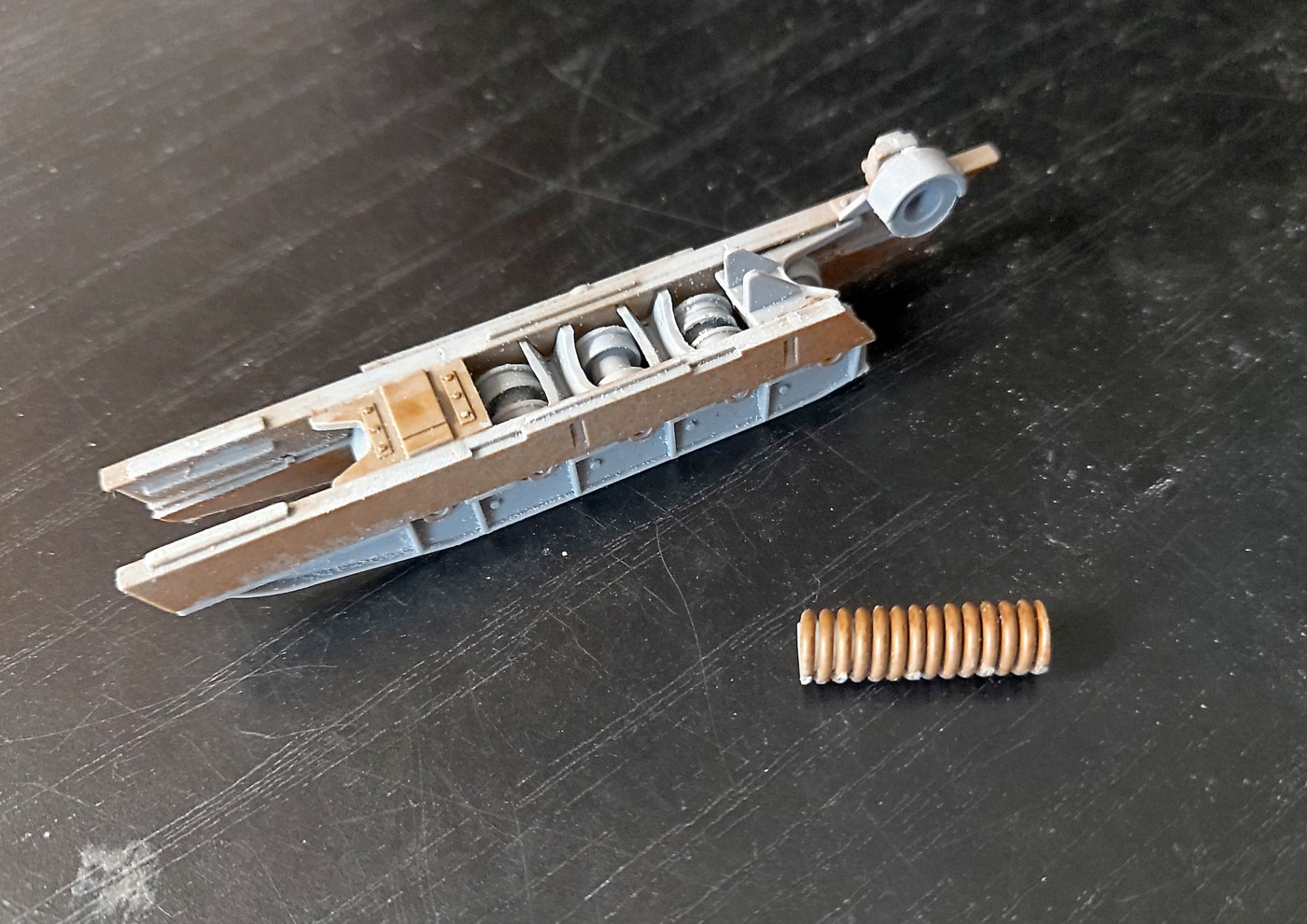
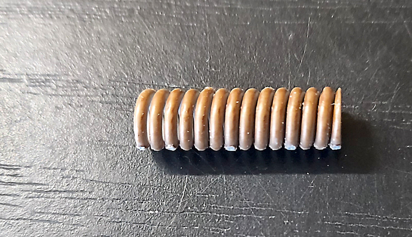
The Spring. Well I thought is was just a solid part that looked like a spring. Wrong. It is actually a working spring. No BS. How they ever engineered it is a neat piece of work. You can see the sprue gates. It with stretch nicely. But I would recommend stretching it too far.
bruce
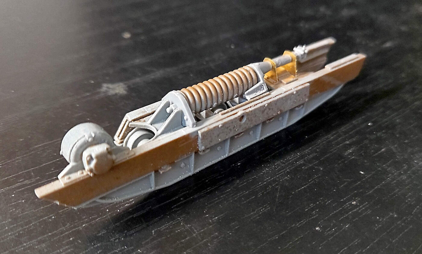
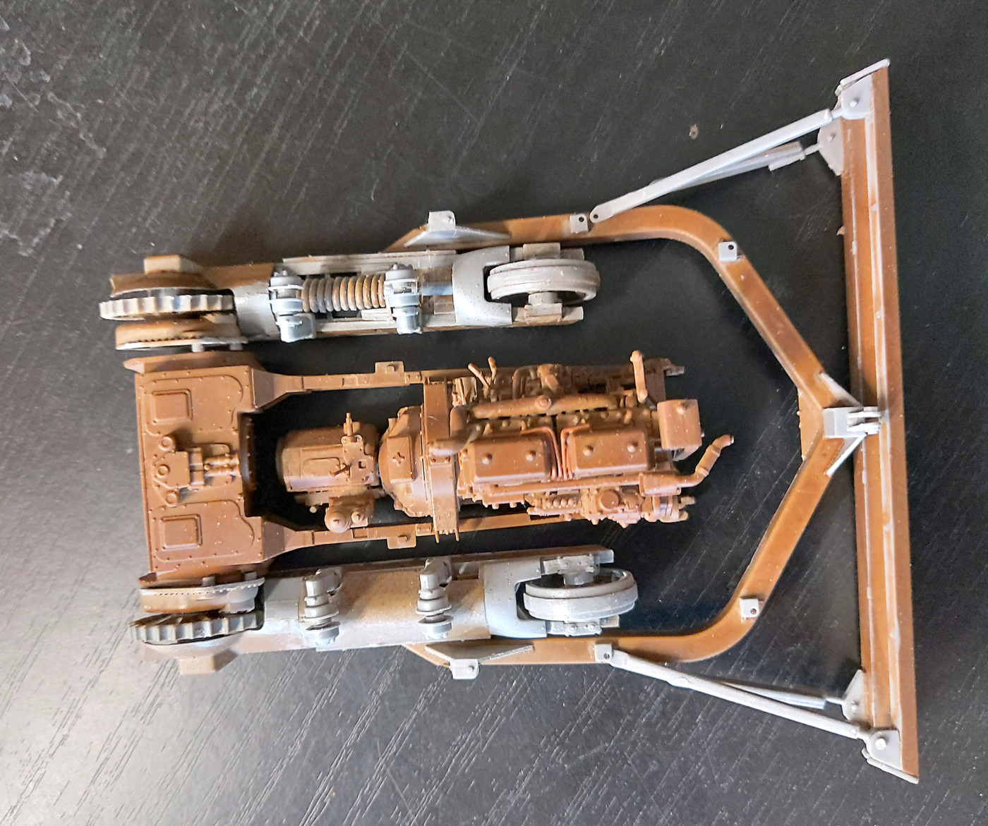
edit. Image of oneside dry fitted. Note the two PE parts. The rear one is best split and forced over the shaft. Large spring has a smaller spring inside it. All of this detail and it doesn’t work and will be hidden!!! .
Another hour at the work bench. There are 52 parts in that one side mechanism!!
The other image is just an idea of how it’s going together.
I’ve watched some online videos about the pros and cons of this kit. I watch Will Pattison’s build. I didn’t encounter the issues he had. I haven’t encountered any of the horror stories so far. Sure the instructions are a bit vague at times. What instructions aren’t? Fit of parts is good. There are parts that are there that will never be seen again so what’s the point of having them? But the builder knows they are there. Do you look at the real thing and complain you can’t see it all?
The large spring intrigues me. MiniArt have engineered a gem of a part. Install it and it doesn’t function and will be covered later. Although I have a plan to show the spring on one side.
bruce
This model looks was more complex than I thought. I will forward with heavy interest how it turns out.
Just a clarification. Above I referred to Will Pattison’s build. (You can find him on youtube). In fact his bulldozer isn’t the same kit. But close. There’s a few differences. Mainly in the way the blade is attached to the dozer.
bruce
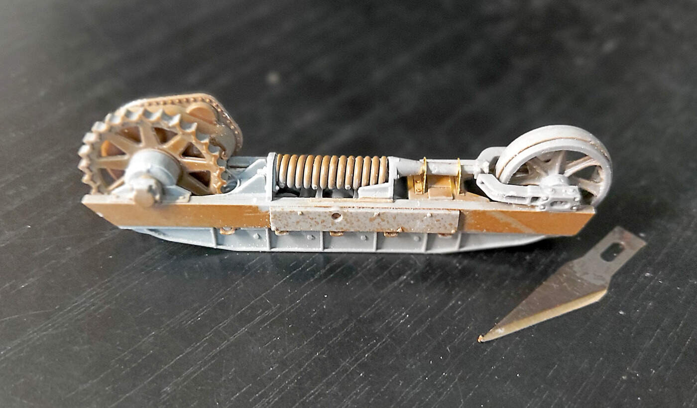
I finished the left side running gear. All the springs etc are covered up in the right hand side. So I left the center cover off on the left side so some of the detail can be seen. Photos of the real thing have the covers on. I’ve found only one or two images with the covers off. I’m assuming the covers are to keep dirt etc out of the running gear.
The two rollers arms on the top prevent the covers from being removed later on. That’s what I was after on the right side but it never worked out.
I’ve hit a bit of a road block at the moment. I had intended to do some more sub assemblies but I think I need to do some more painting first.
Just a note of caution for anyone taking on one of these kits. There are a lot of parts in each drive assembly. The instructions are vague. Don’t force anything and keep an eye open for twists and misalignment. I got a bit to clever and made the left assembly too tight. I have a twist in my knickers over it. Another job to tackle later.
bruce
Roadblock!!
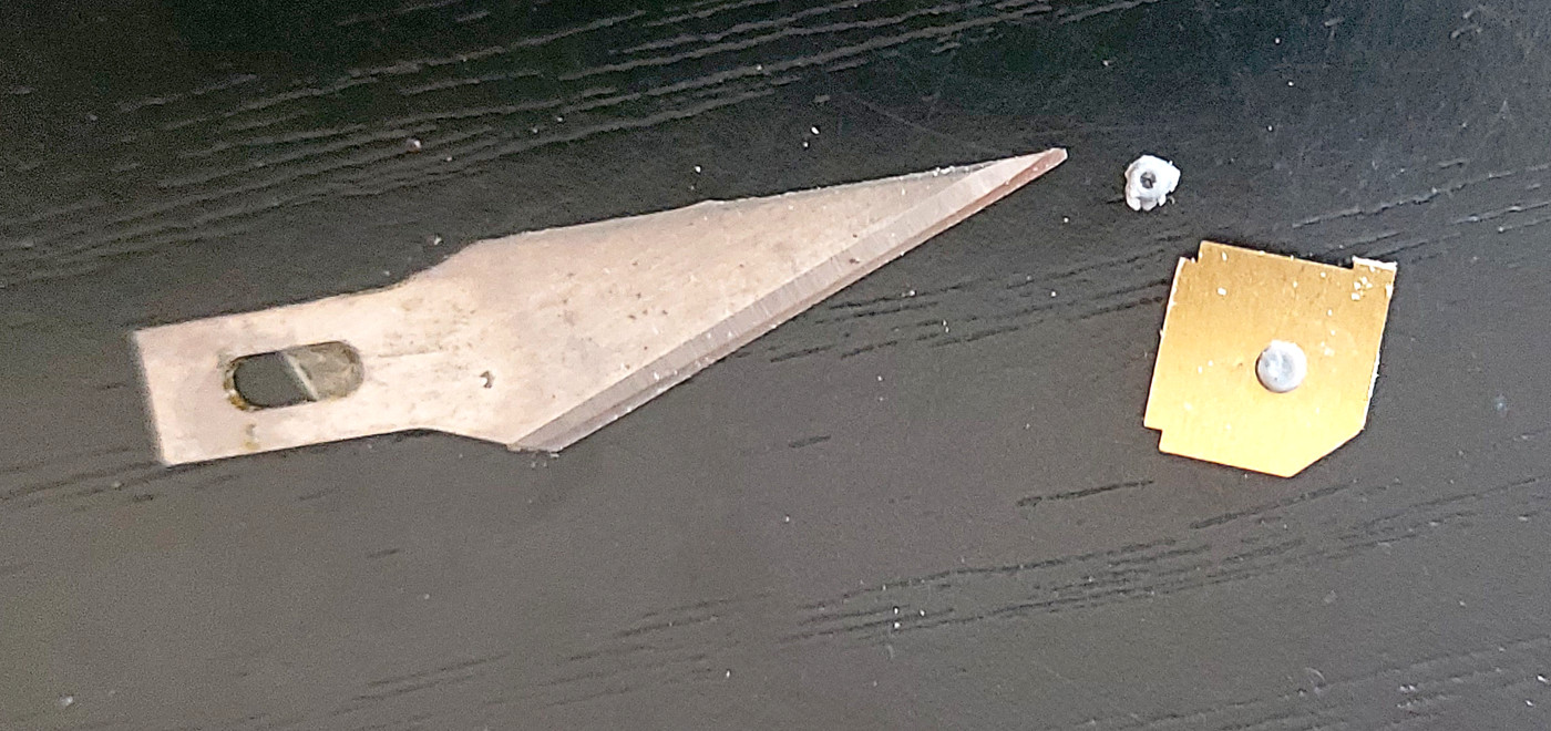
Every kit has its moment. I’ve hit the first big one.  Behind the drivers seat is the cable mechanism for the blade. Well it’s made up of some PE and some small, very small, microscopic, (get my point?), parts. No matter how I hold my tongue I can’t get those small bits into the corners of the PE. The image shows just one side of the PE. It is actually folded and has two sides with a pulley in between. The small part goes between the two sides. Oh and it has to be up the right way with the hole at the top. There’s four of them. My smallest tweezers don’t work. Maybe it’s my eyes!
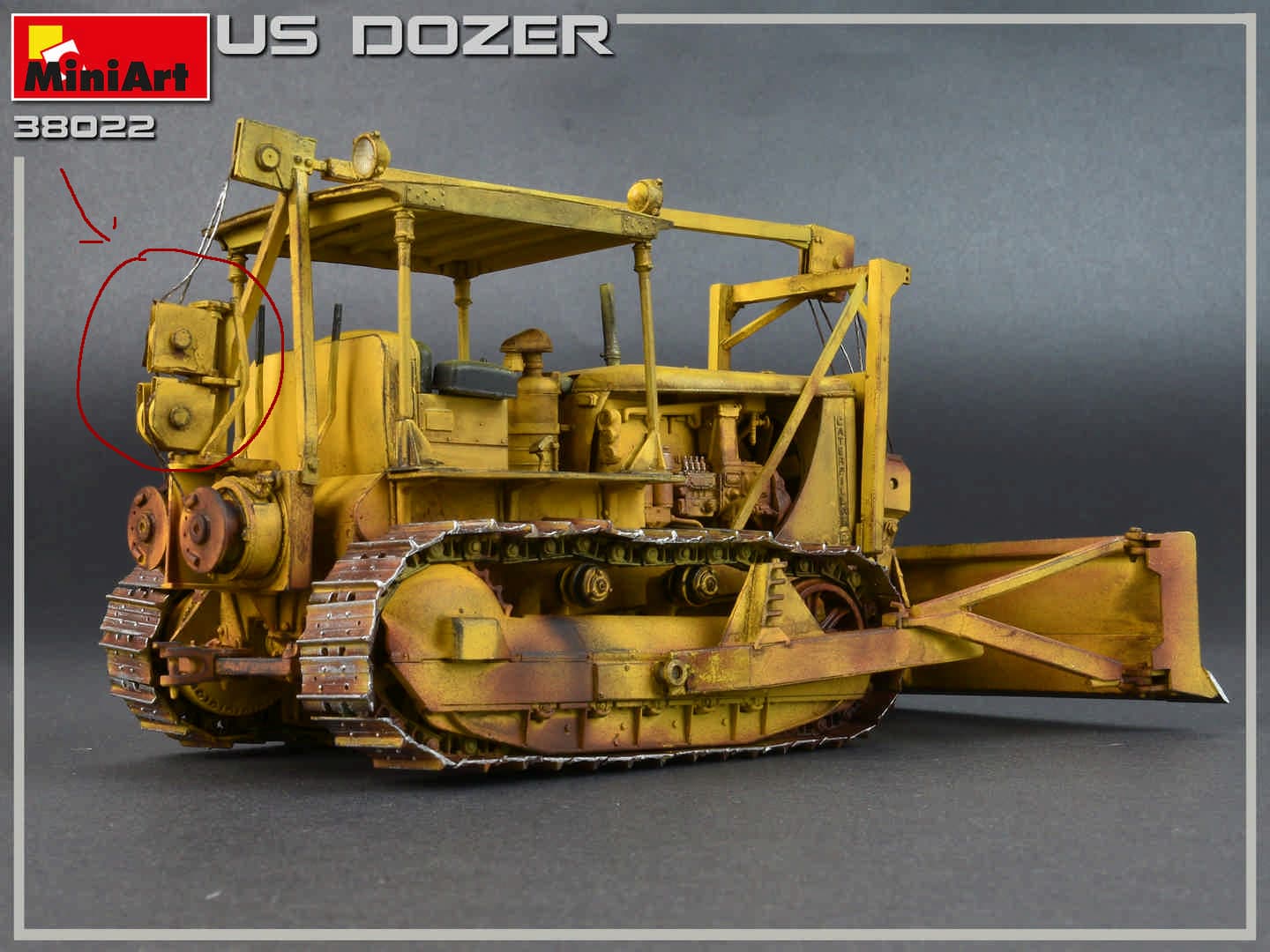
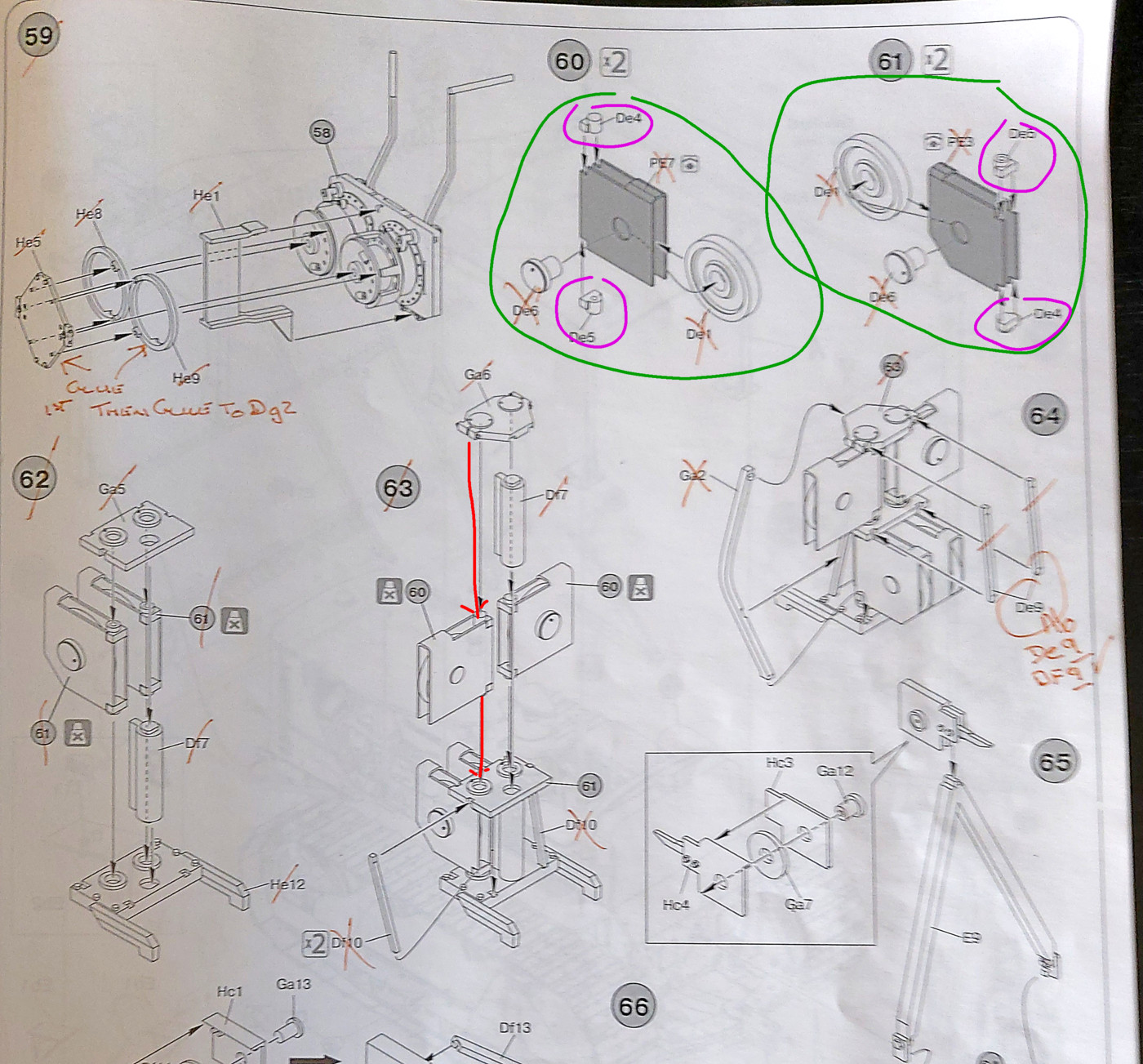
I’ve circled the MiniArt image for the parts in question.
Watch this space!
bruce

No coffee or alcohol beforehand. Sit and meditate a moment. Then put a dot of CA where the part goes, Pick up the part with the tip of a #11 blade, and place the part. Let out a large sigh of relief.
Depends on the person, some need to mellow out beforehand. So 1/4-1/2 dose might be good for the person. I agree on meditate to slow the breathing, on the exhale, slow squeeze the trigger, I mean move the part in place. Inhale and repeat x3.
Agree with Matt. Use the point of a #11 blade to pick up and place the part. If the part will not be stressed too much you might want to try Gator Grip instead as it will give you more time to position the part. Good Luck.
OK, an update. No Coffee and no beer. Just plan B and C. Or was it plan D?
Instructions. Step 60 to 64. Parts De5 and De4. (Pink circles). Those little suckers had to go in the right way around and the right way up. I showed the size of them above. After many tries and a lot of naughty words I gave up. They had to be just right to fit where they were meant to fit. So.
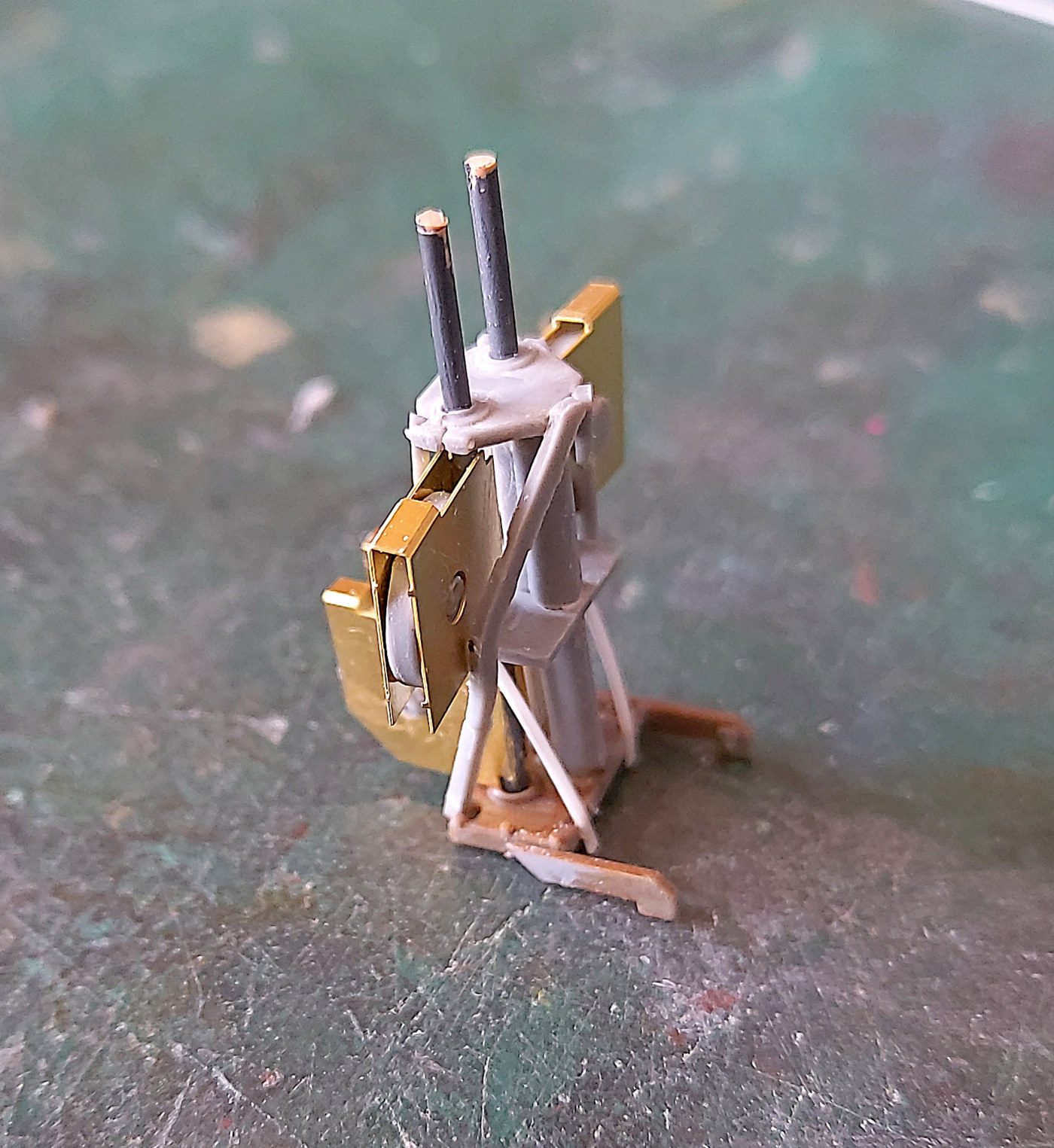
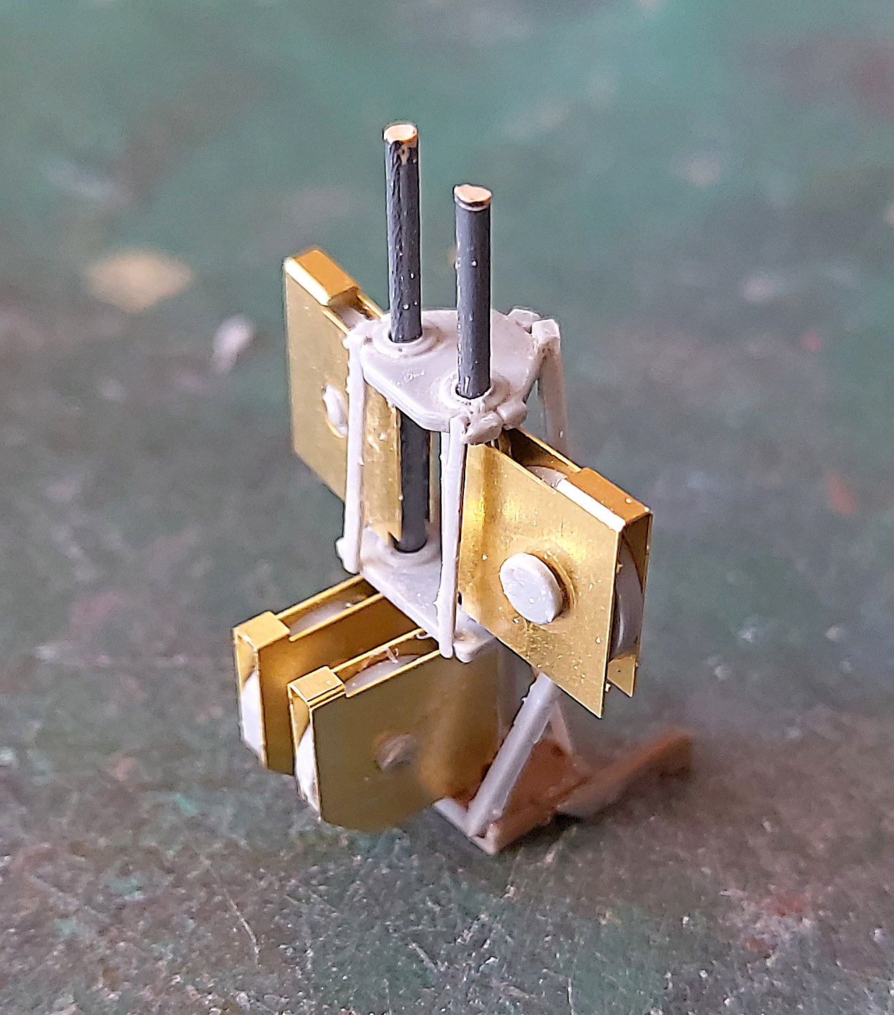
So I figured a new approach. I binned the kit parts. I drilled out Ga6. Found a bit of 1mm rod. Passed through the hole and down to part He12. With me? The PE parts were then glued to the rods. (The rods are sticking out of the top at the moment. They will soon be trimmed to be flush with the top of part Ga6).
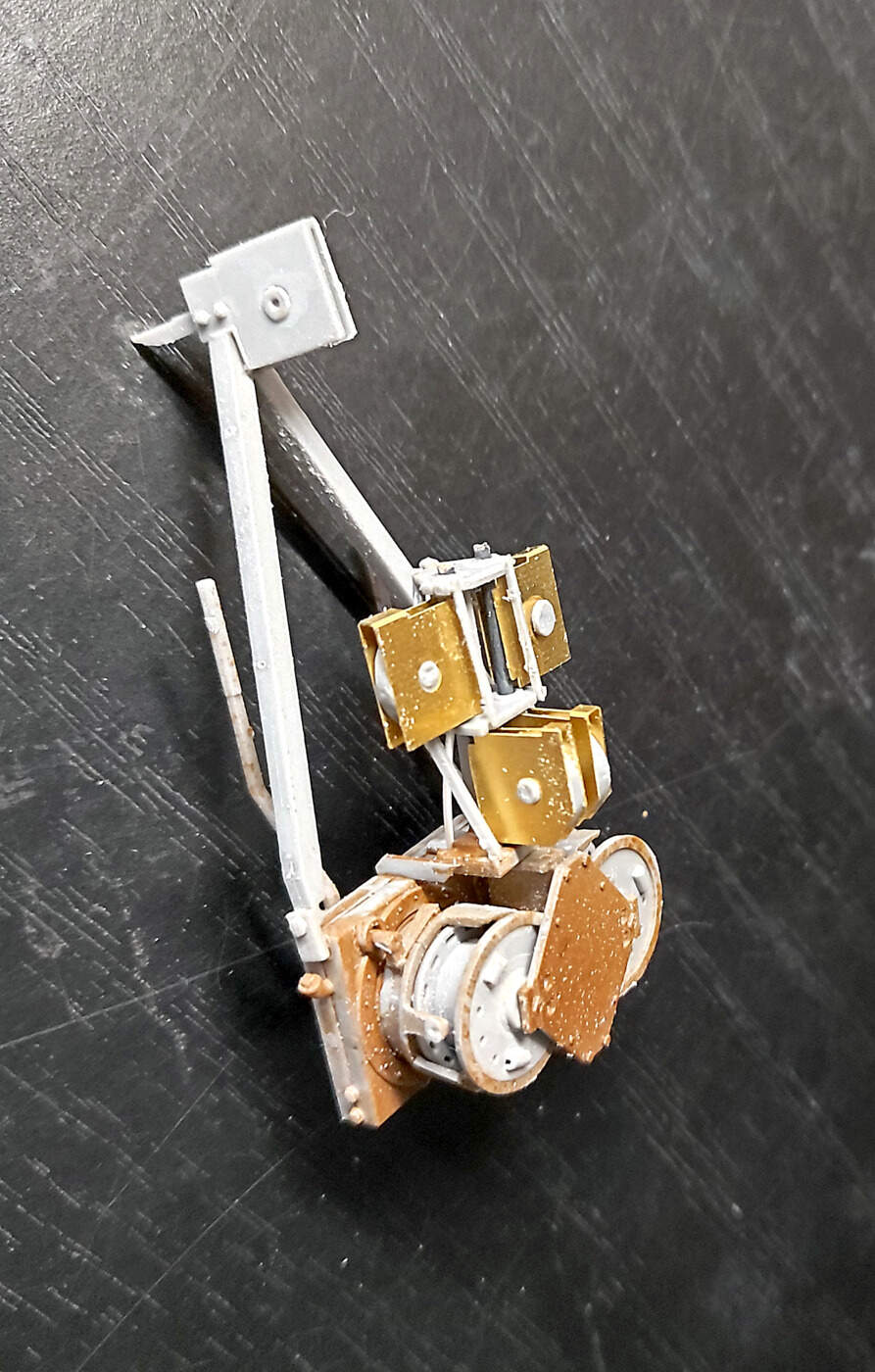
For anyone contemplation this kit keep an eye open for part De9. It’s not there. It should be part Df9. Df9 and Df10 are so small and fragile I gave up on them and used strips of styrene.
Don’t get me wrong. This is a great kit. A challenge I’m up for. But the sadists at MiniArt must be getting a great laugh out of folks working with so many small parts.
Then next problem will be figuring out how to rig the cables. I’ve search the net. Every image I have found are abandoned/junk versions with out the cables. But it can’t be done until the dozer is all but finished because I have no idea how long the cables have to be.
bruce
The images are key here.
edit,
Finished. Just a dust off and some paint. Oh and figuring how to run the cables. FWIW it sits behind the drivers seat.
Would this help ?
https://pbs.twimg.com/media/DNjbWvKX0AIuCOT?format=jpg&name=large
All you need to know about the LeTourneau Power Control Unit :
https://radionerds.com/images/e/ec/TM5-9282.pdf
H.P.