“ My tikki wrench boss ! “
Indeed I did - both movies . My wife and I were laughing recently over the 25 year anniversary bit for the Titanic movie . It was the last movie we went to see in a theater so haven’t seen the inside of a movie theater in 25 years it seems.
If I may I would like to share something -
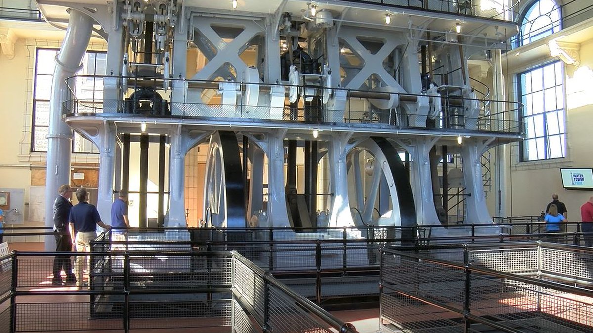
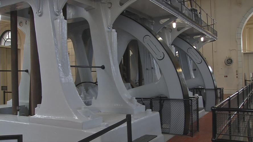
I grew up about 8 miles from this beautiful Allis-Chalmers engine located at the Louisville Water Company pumping station No. 3. In those days it was open to the public 24/7 and I would often take late night dates here and never were they not impressed.
Triple expansion engine with 17 foot flywheels, driving 3 siphon pumps. The entire structure over 100 feet tall with the actual pumps being in a huge pit below ground level. (and Ohio River level as well)
During the great flood the water level got up above the fireboxes and put out the boilers. The city rented two steamboats, moored them next to the pump house to provide steam and the city never lost their fresh water supply.
This still stands today on display at the Pumping Station along with a small but very nice Museum.
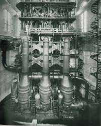
(All photos found on line ! used here for discussion purposes ONLY)
Video in operation:

2 Likes
Neat stuff Michael - thanks for sharing !
While the loftsman/ boat builders were my father’s side , my maternal grandfather and one of my mother’s brothers were both marine engineers and the family emigrated to the USA from Tonsberg , Norway around 1916 IIRC - my mother was the youngest of five and the only one born in the USA . My uncle retired from the sea later in years and was the engineer in a textile mill caring for a similar engine but single cylinder.
After a fun side trip into the world of steam engines it’s back to the subject at hand.
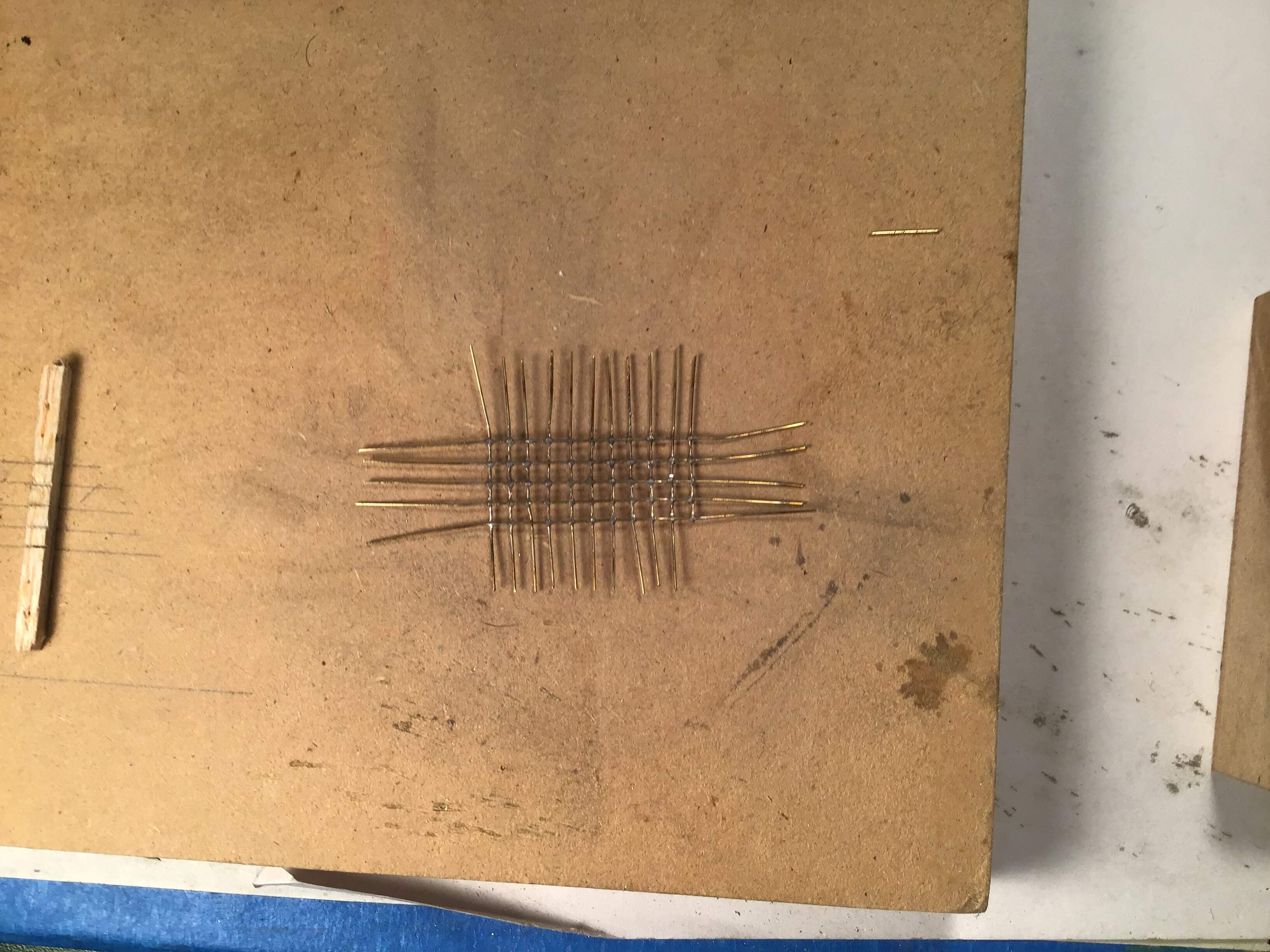
I’ve made up the headache rack but not without a great deal of trial error. I initially tried soldering with the resistance outfit - worked ok for a few joins but then the ground clip burned through the thin wire .
I suppose this illustrates the difference between the lower price unit I purchased and the considerably more expensive variable current model .
I then tried again using a method I used a few years back on my Japanese Hucks type starter truck
build . I ground up solder on sandpaper and mixed the dust with flux and carefully placed a dab at each joint and micro torched it . All but one joint failed . Worked fine years ago but not this time .
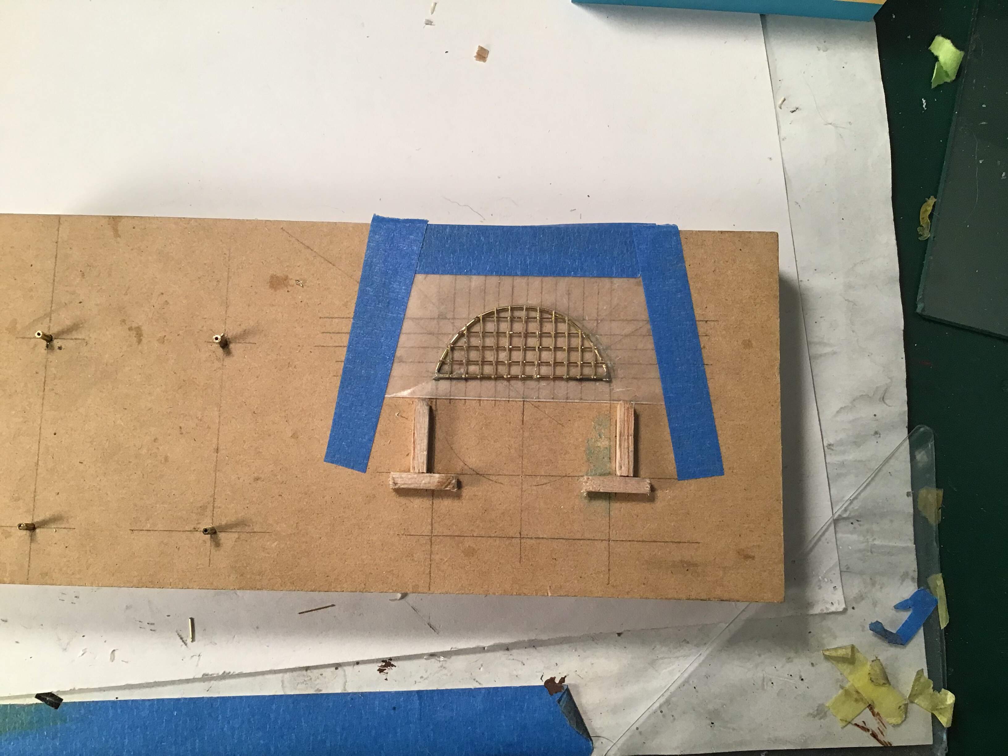
Third try I used a tiny dab of paste flux at each joint and cut tiny pieces of solder and placed them in the flux at each joint and torched . Good bond this time but too much solder to clean up .
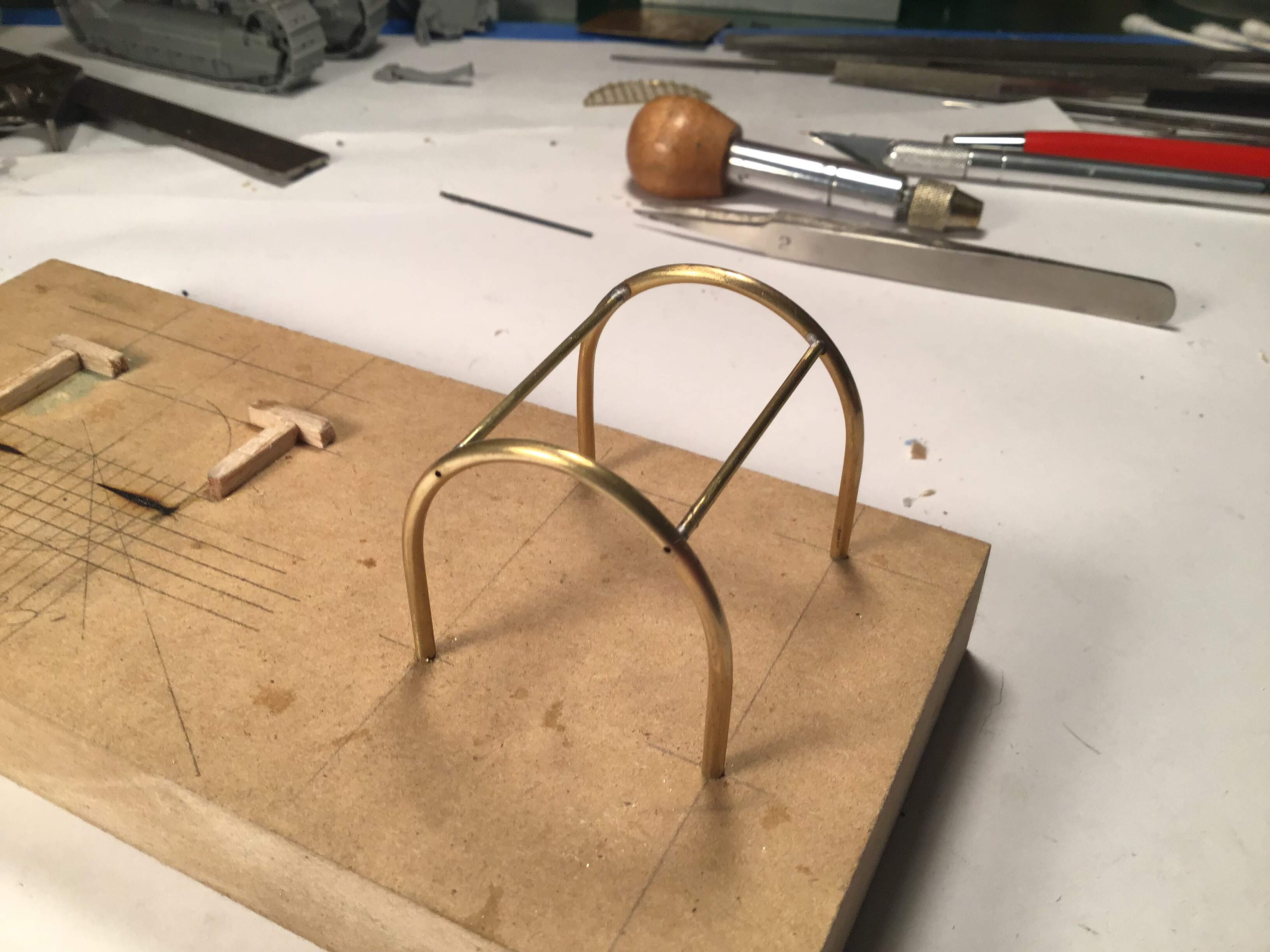
Caved in on round four and used epoxy .
The fixture for the first three tries…
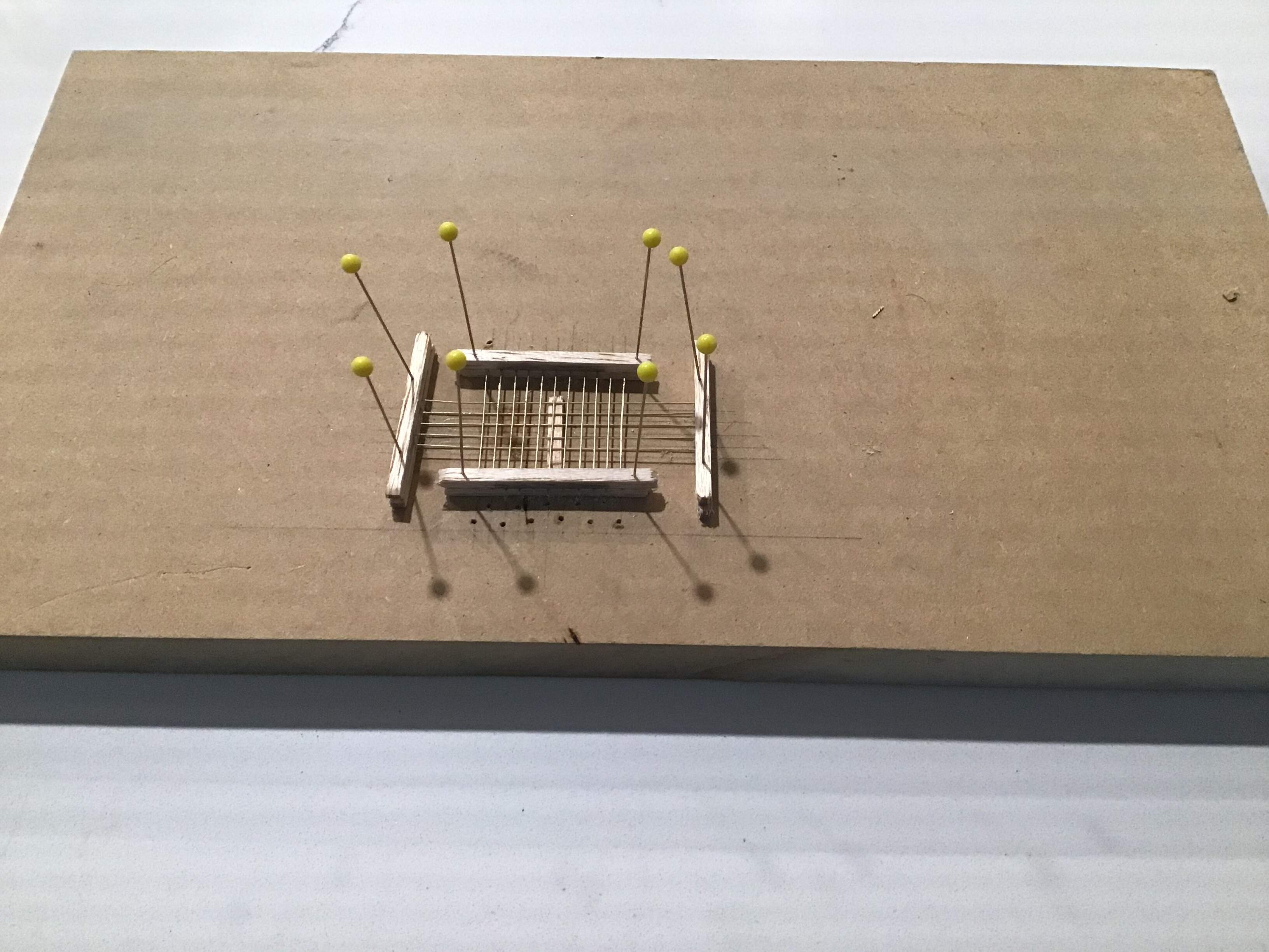
The third try …
and the epoxy version…
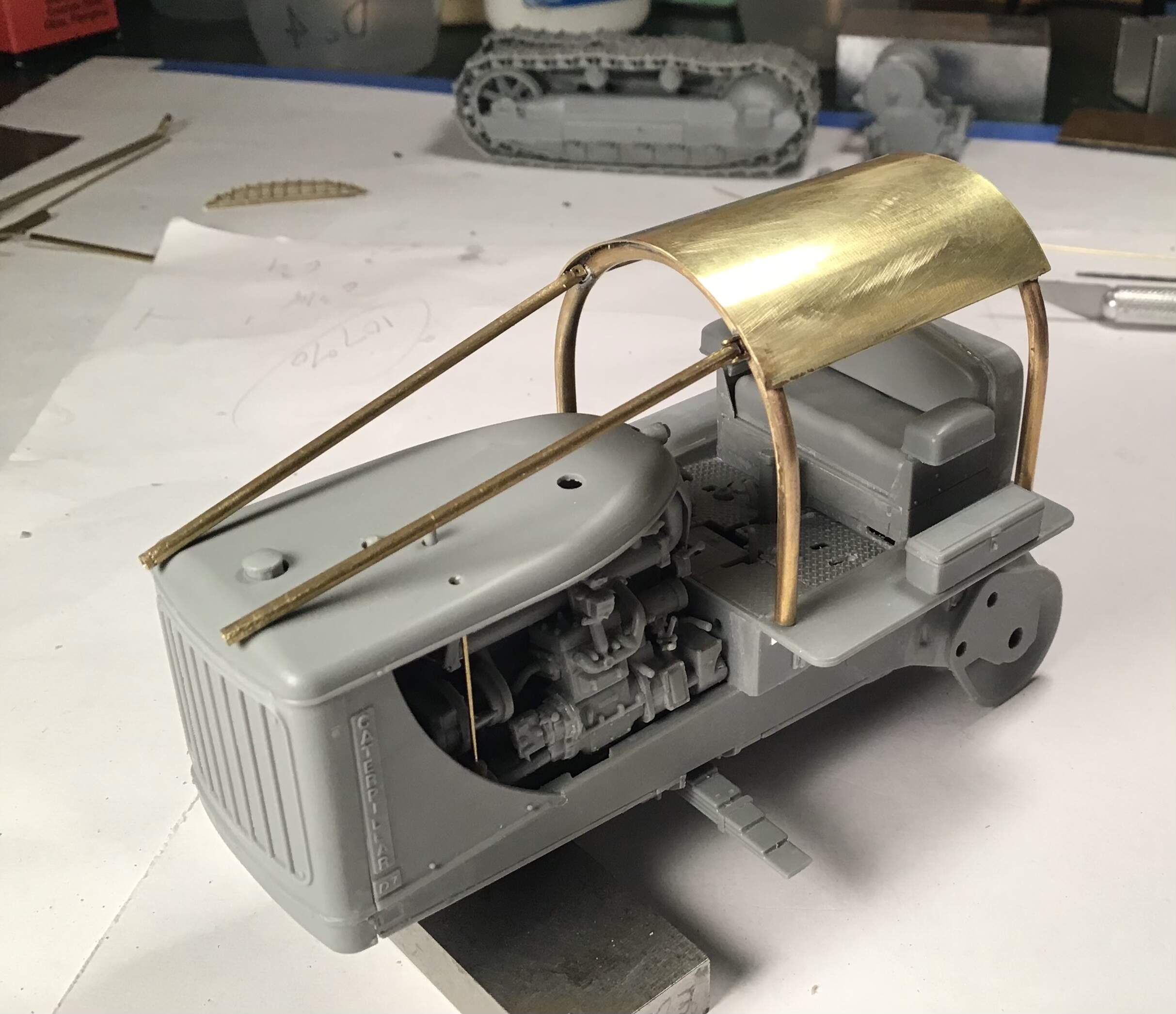
The roof structure soldered up . Resistance unit works beautifully for this .
And a dry fit off all so far …
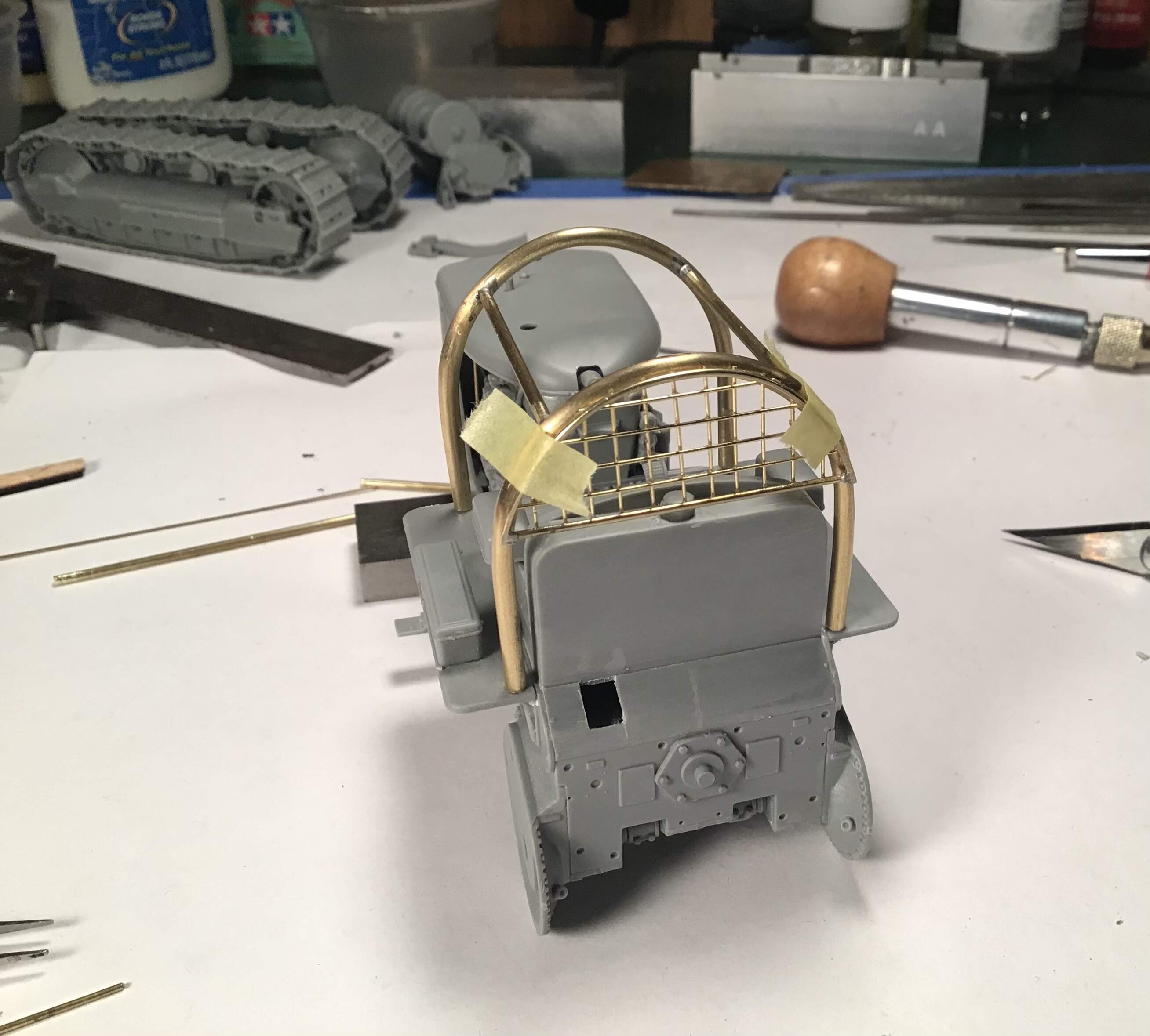

Next up will be making up the ball joints for the guards over the engine area and the curved roof itself .
Thanks for looking and all comments always well.
RT
14 Likes
Noice! ![]()
1 Like
Holy crap! You made that screen? Didn’t anybody ever tell you that is physically impossible to make by hand without it looking like garbage? Richard that is a phenomenal bit of scratchbuilding. It looks perfect. I am humbled by your craftsmanship. Outstanding!
5 Likes
Thanks all for the interest and compliments.
Haven’t had much bench time as my wife and I have been babysitting our 7 month old granddaughter for a week . Love her madly but it takes a lot of energy when you are nearly seventy.
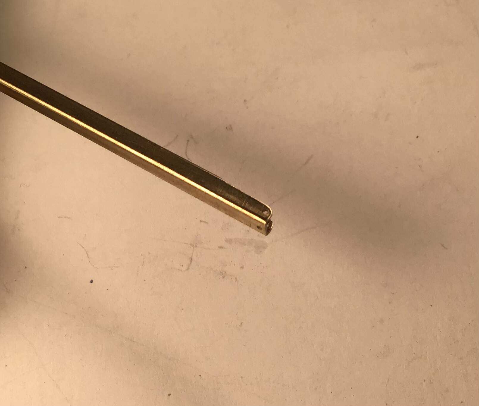
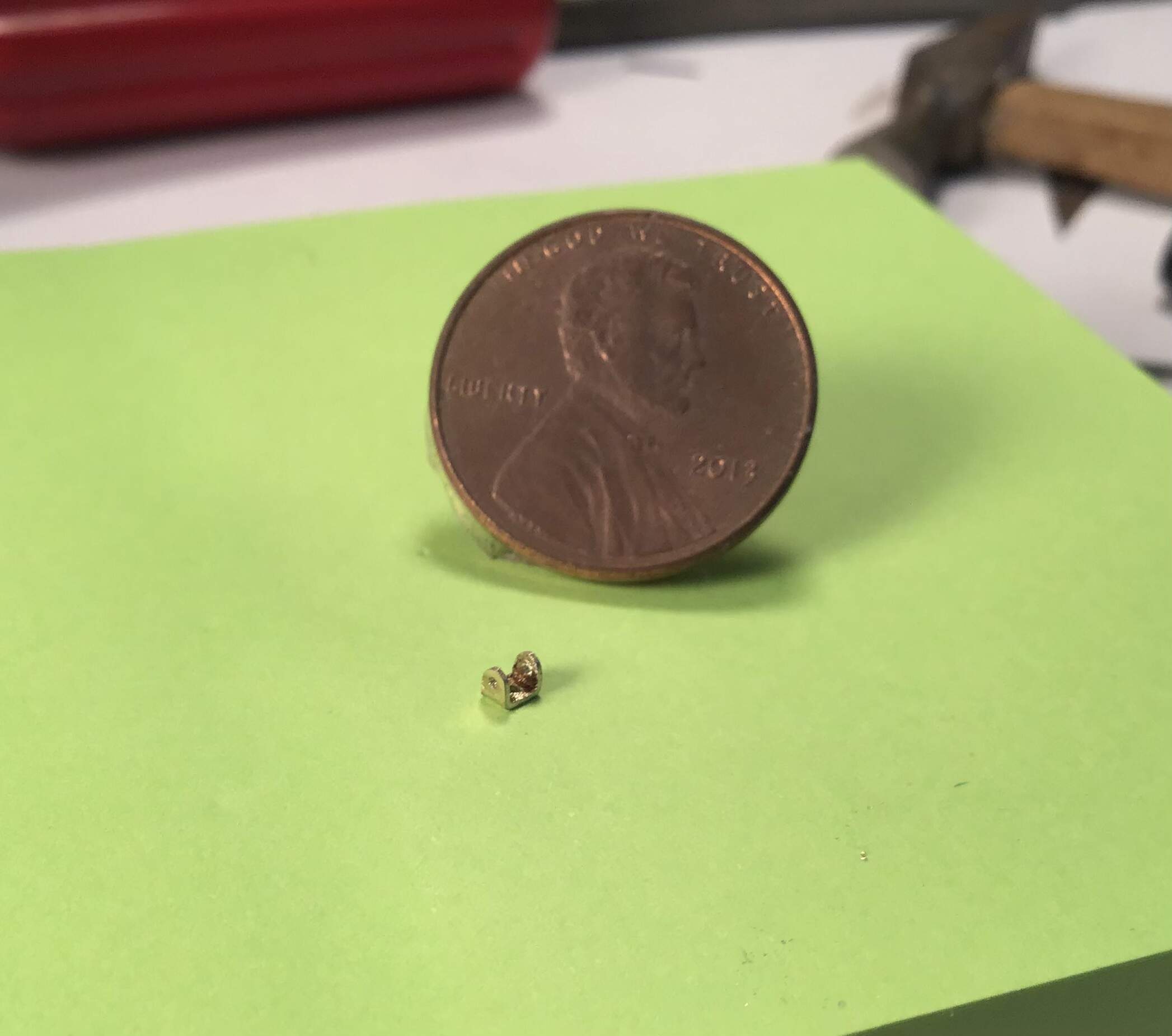
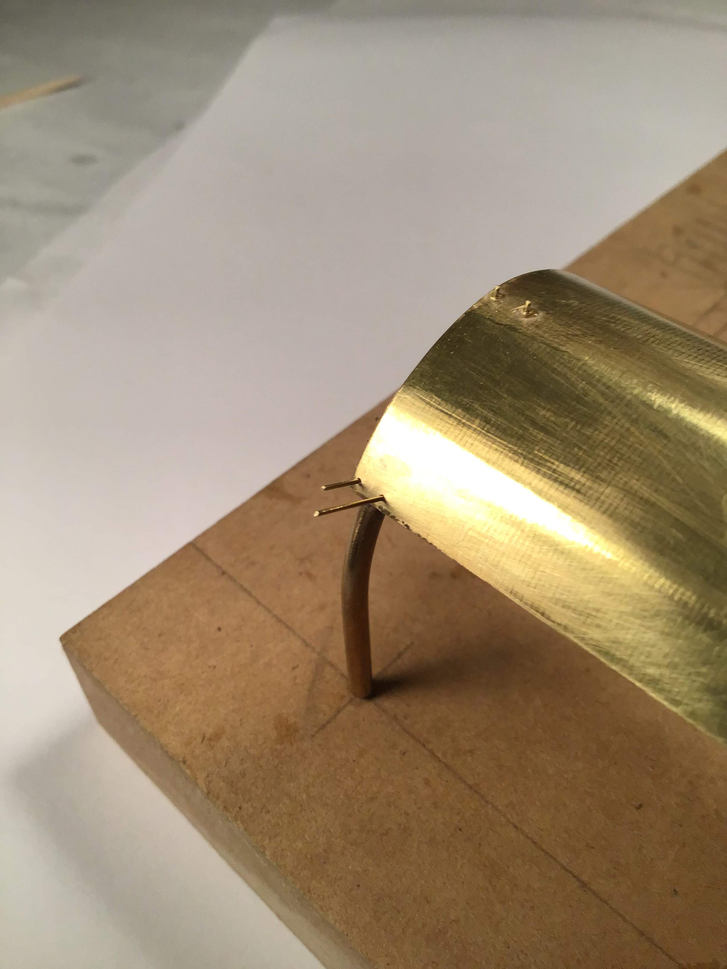
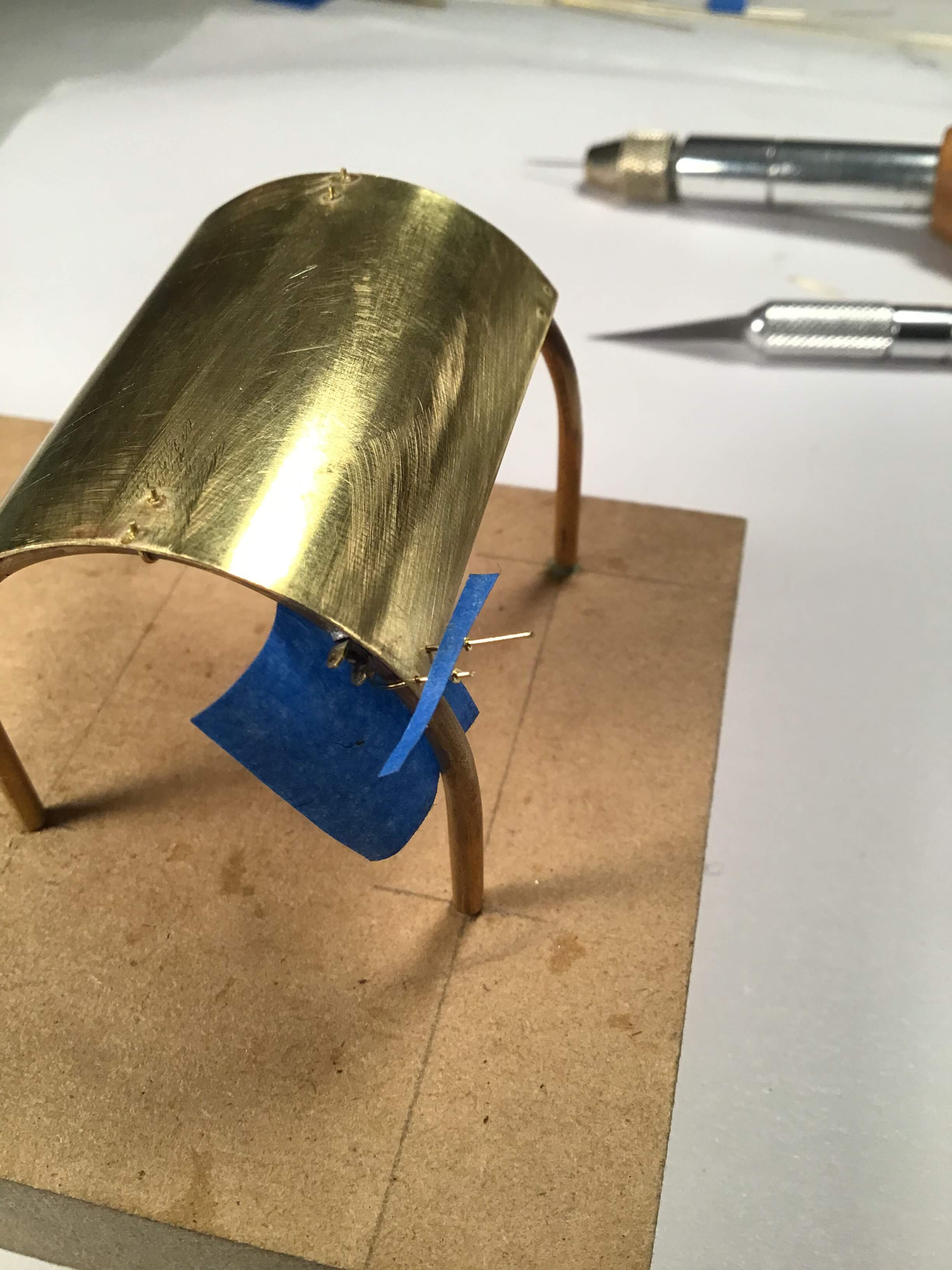
I managed to form the curved canopy out of sheet brass and made up clevis’ for the front guards .
Clevis made by filing one side of a piece of square tube to create a channel - holes drilled and filed to shape .
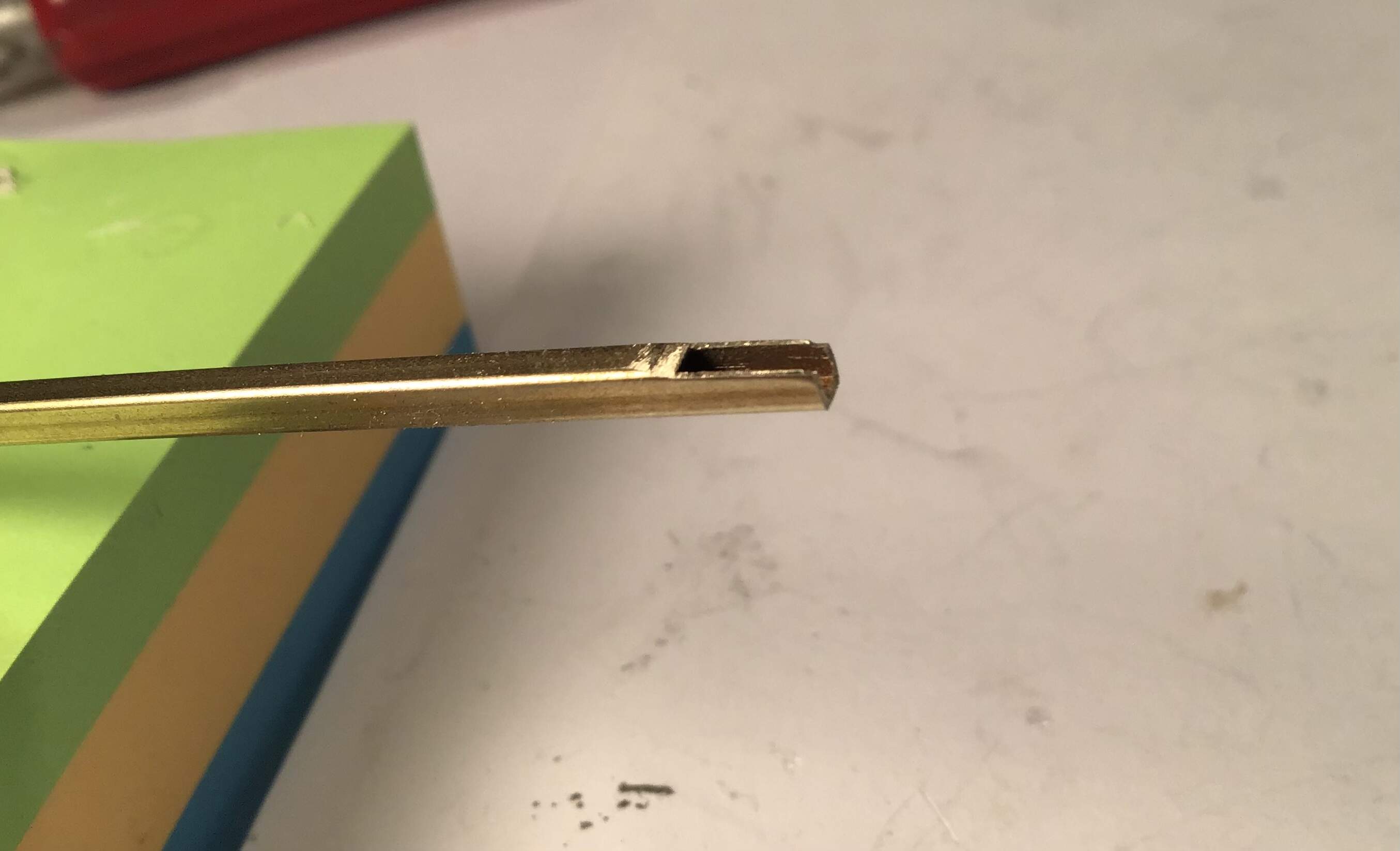
Roof and clevis’ soldered on …
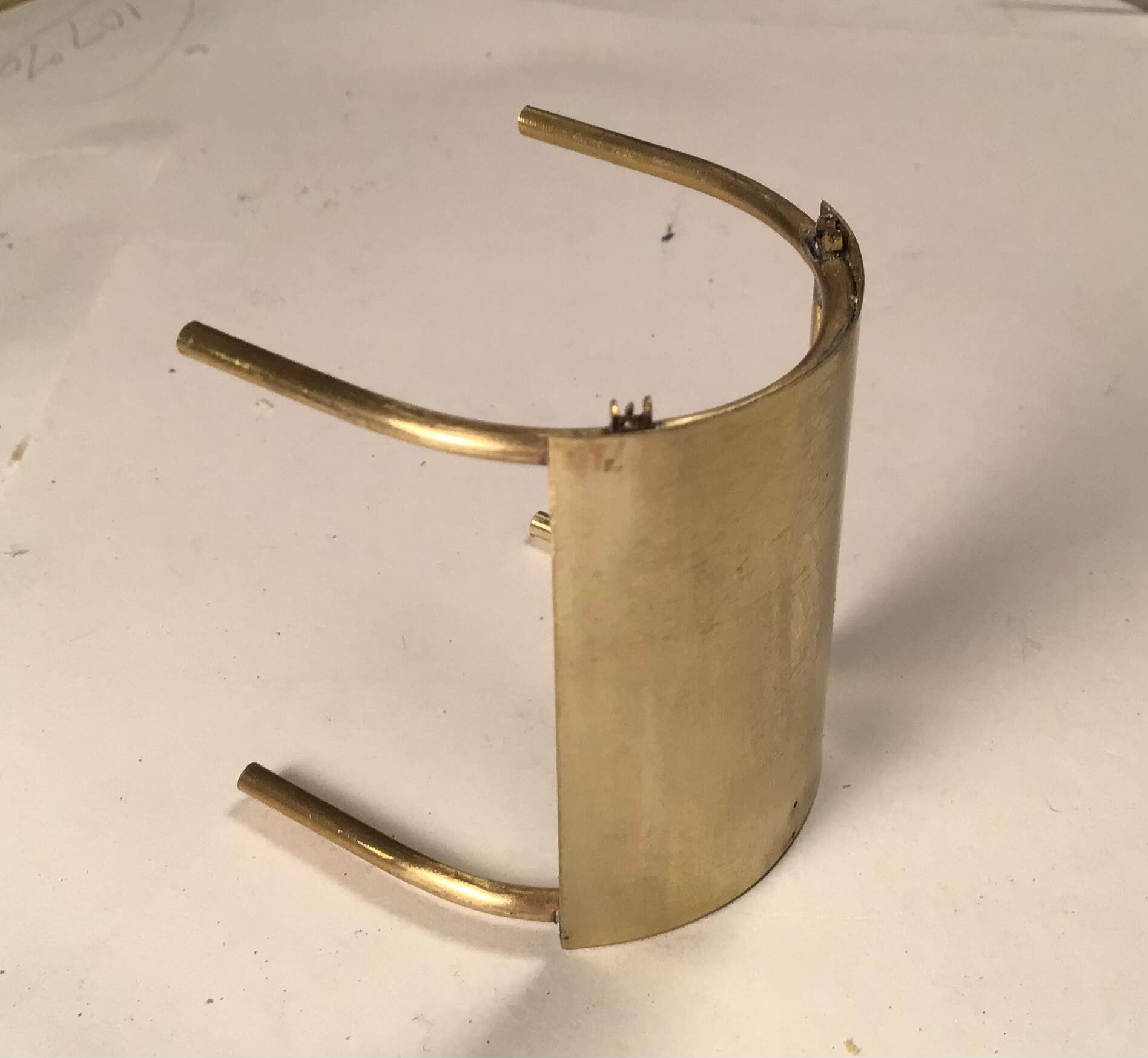
Thanks for looking !
16 Likes
Nice attention to detail ![]()
2 Likes
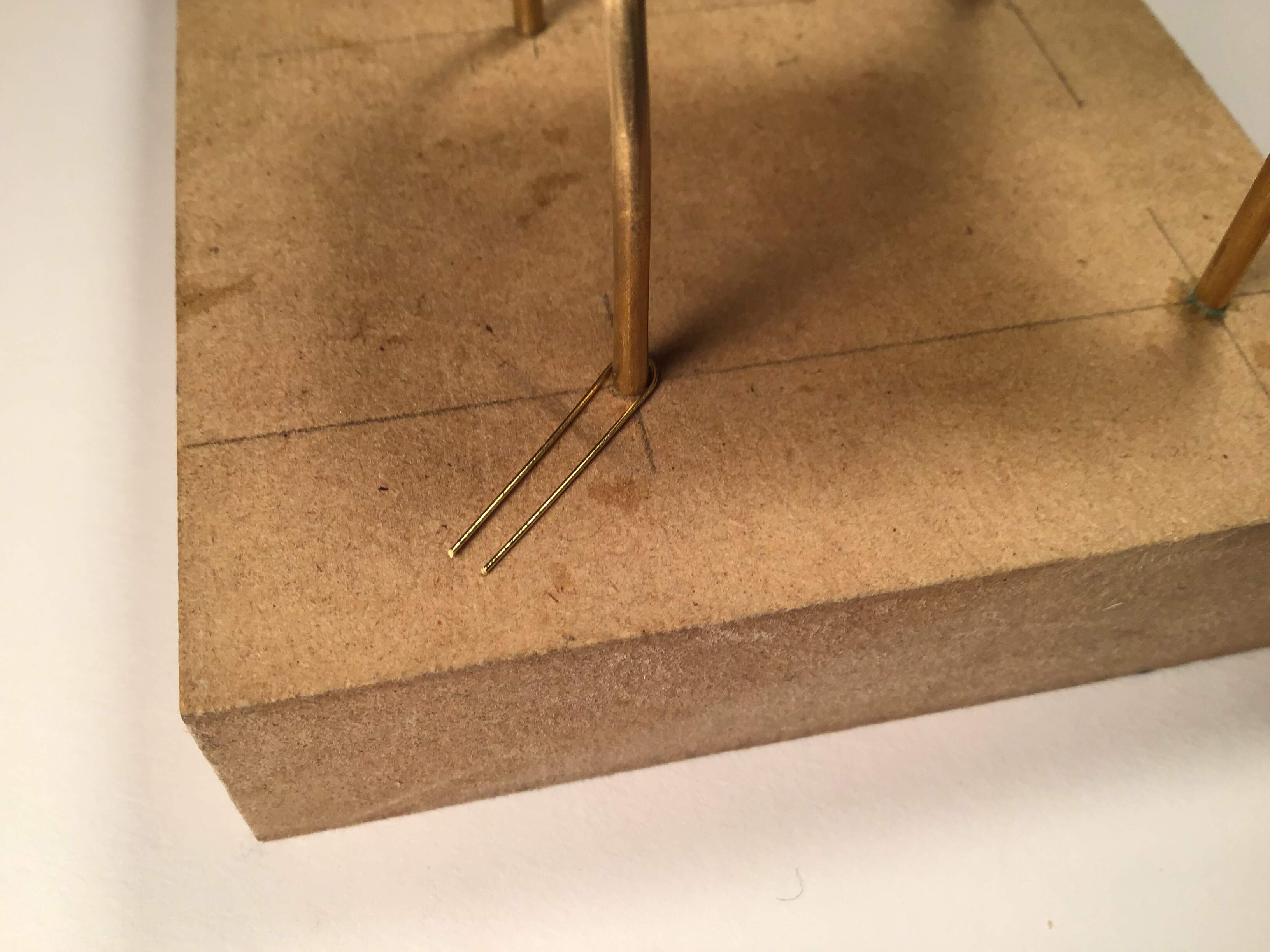
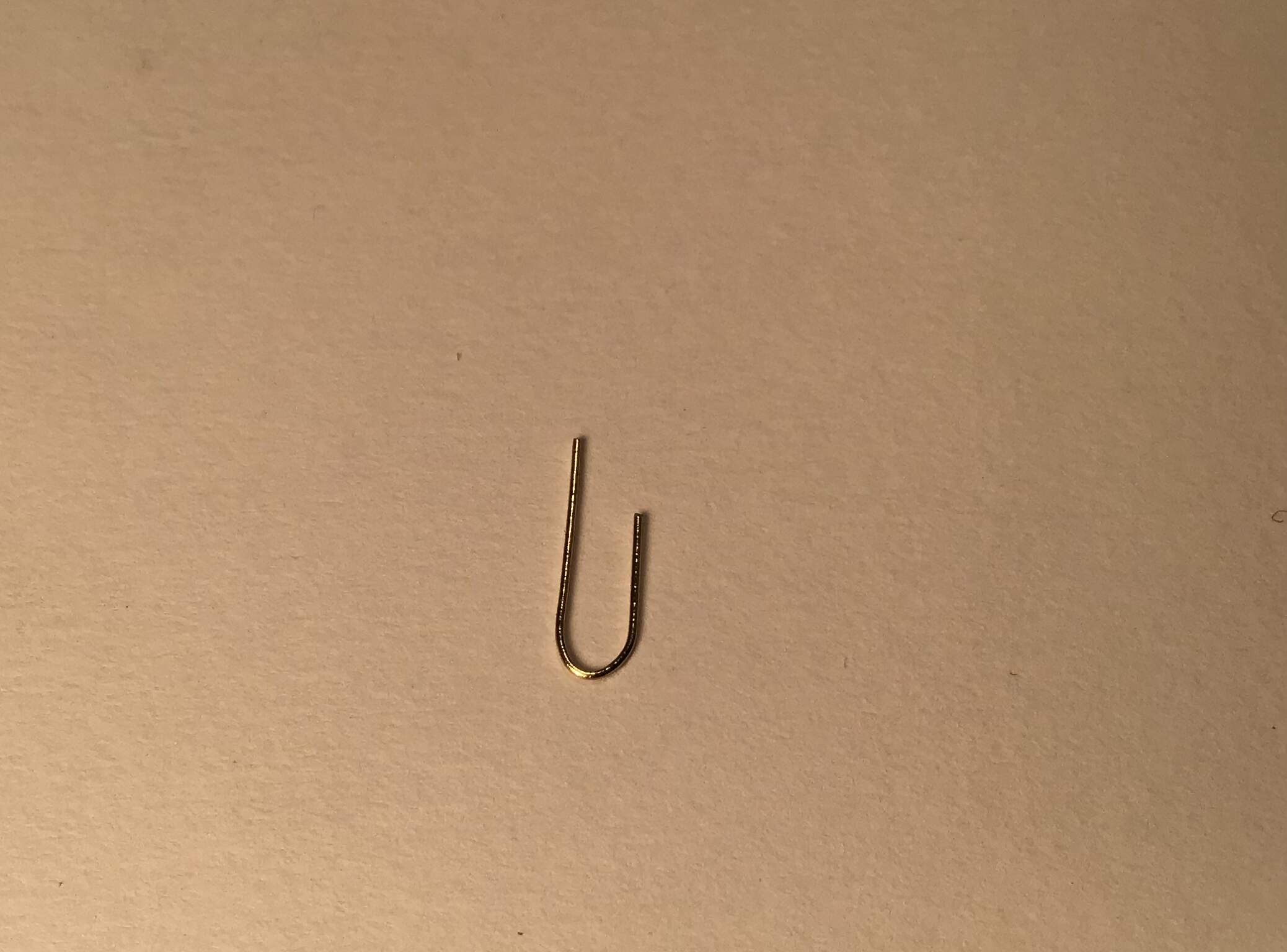
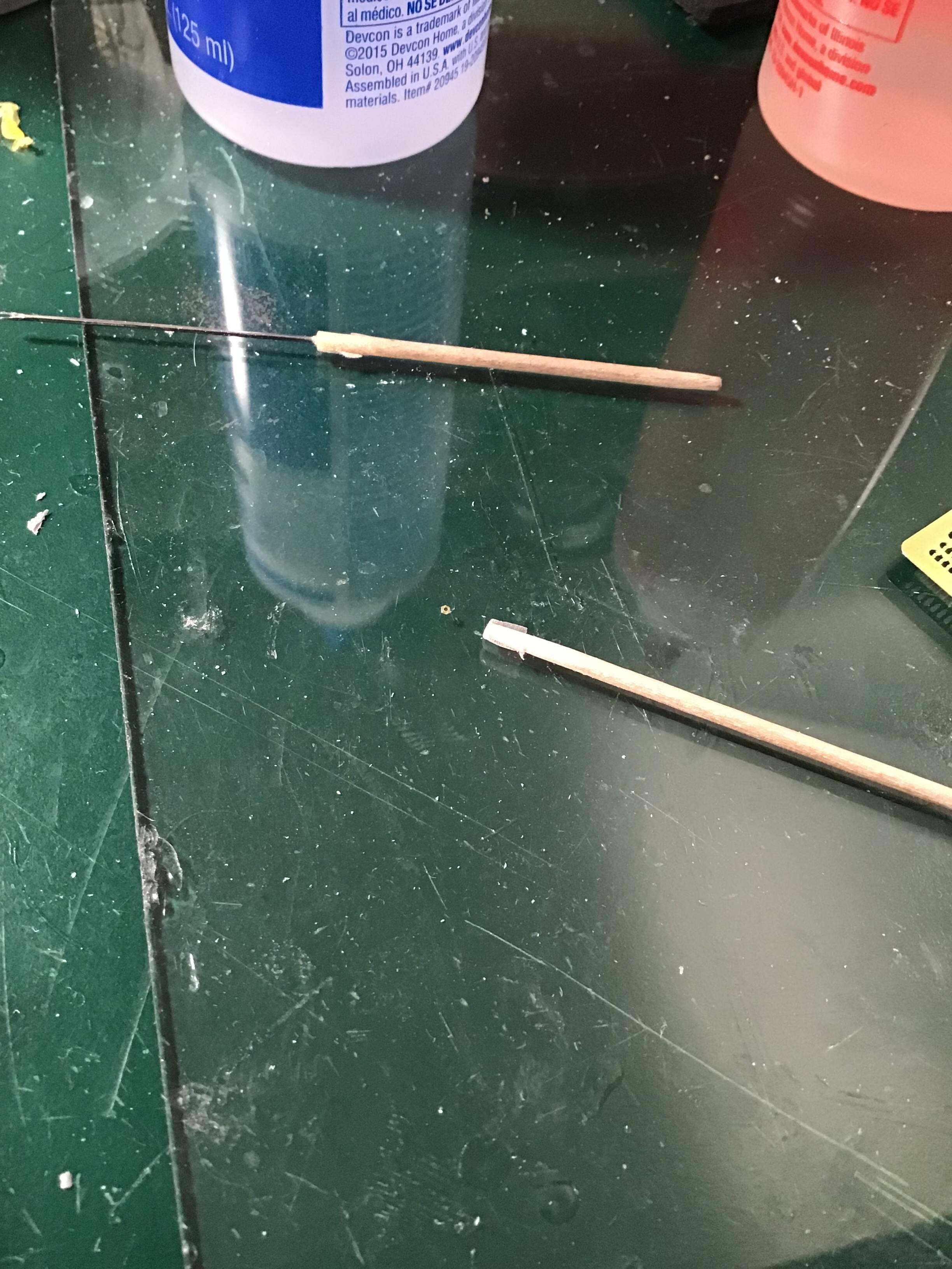
Working on U - bolts that fasten the canopy roof to the framework. I took some fine brass wire and clamped one end in the vise and held the other end in pliers and drew it taut to straighten. Next short lengths were cut and bent around the framework to form the U - bolts . U bolts then cut to overly long rough length - ends made unequal in order that one leg at a time could be inserted through previously drilled holes in roof straddling the framework.
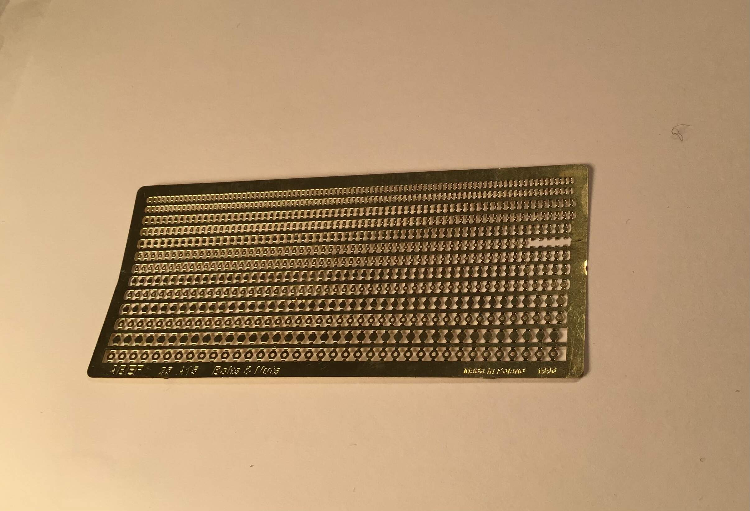
I initially tried to punch out nuts from sheet styrene with a hex punch and die but with a hole drilled in the plastic the nuts just crumbled when punched.
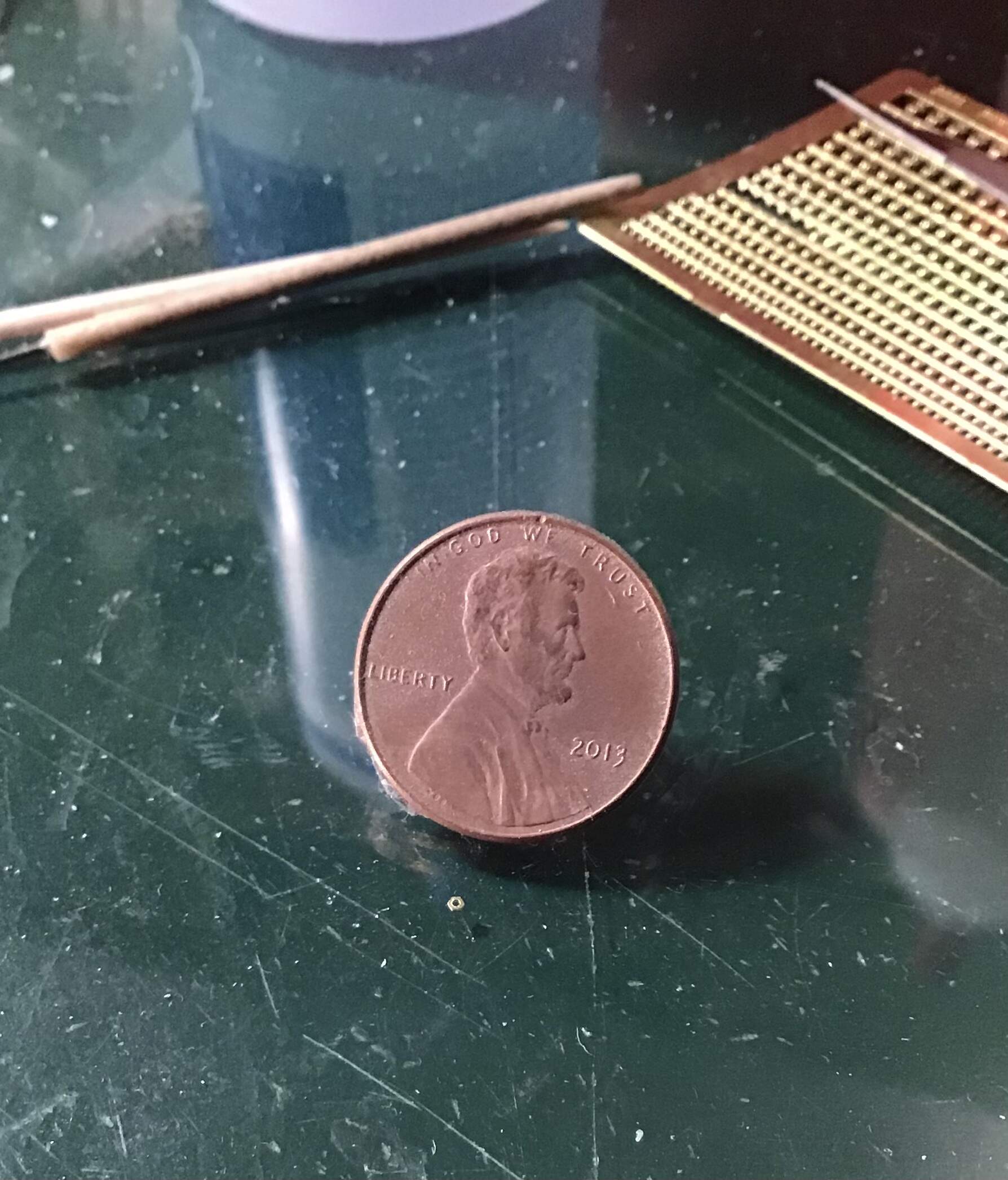
I found an Aber photo etch set on eBay so purchased them which worked much better.
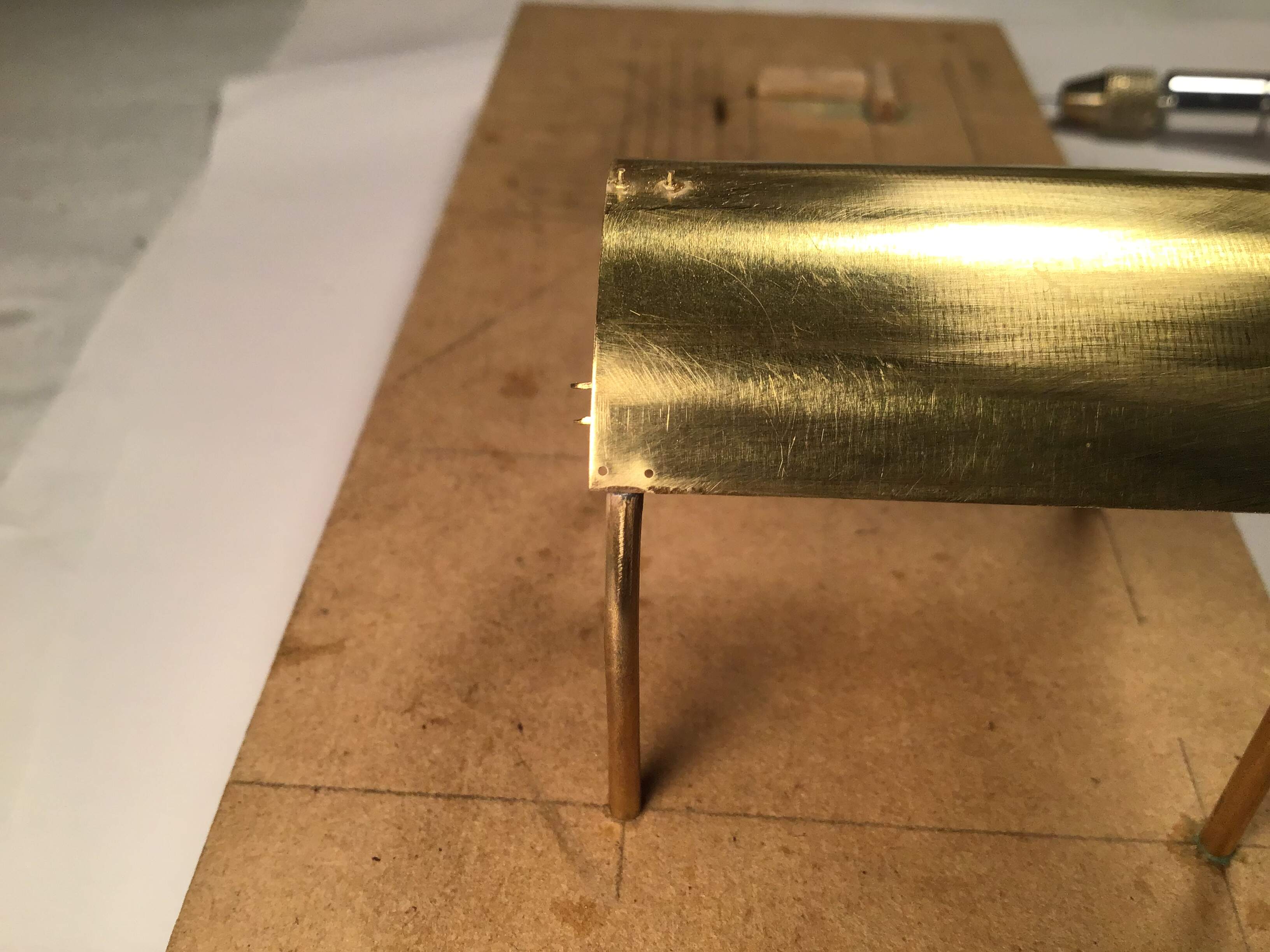
After inserting the U -bolt through the roof with a piece of tape to hold it in place another strip of tape was laid across the ends to keep the nuts away from the roof. A dot of epoxy at each bolt leg , then strip of tape removed and nuts slid into place .
After curing the bolt ends were trimmed and the u portion around the frame fastened with CA.
Don’t even think about touching these tiny nuts with tweezers - prime candidates for launching into oblivion. I handled them with a piece of double sided tape on the end of a toothpick.

Next session should see the canopy system completed and ready for primer.
Thanks for looking and as always, all comments welcome.
RT
8 Likes
Thoughts…
What would happen if the punched out hex “disks” were glued to the canopy
and then drill the holes through the disks and the canopy?
Hard to center the holes?
1 Like
That was a thought of mine Robin and yes it would be difficult to center the nuts but also part of the trouble was the punch / die set has seen better days - worn sloppy fit .
1 Like
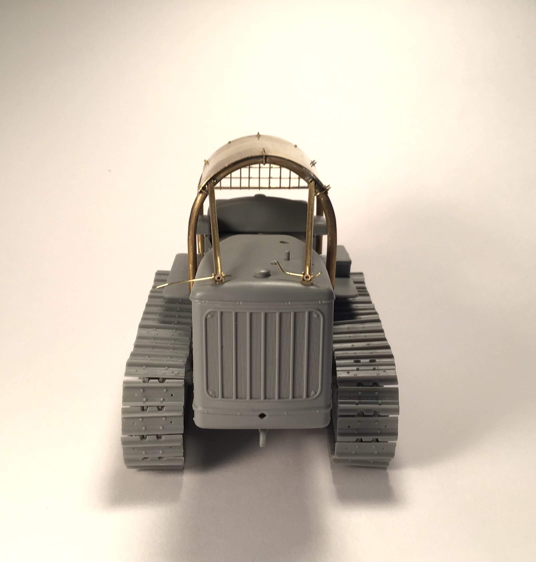
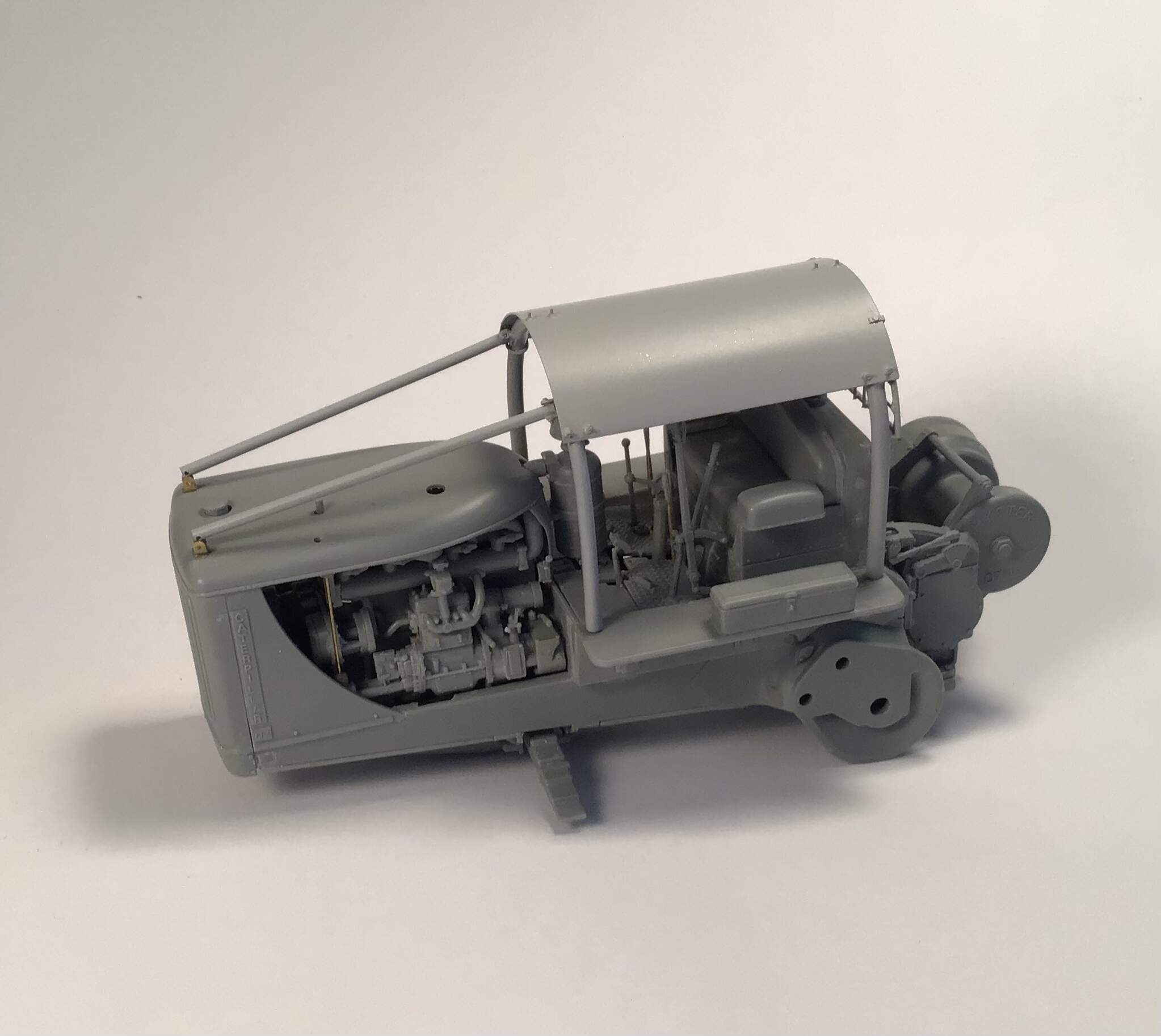
Brass work for canopy now completed and ready for primer . The attachment points for the guards above the radiator are temporary as the canopy system will be removed for painting.
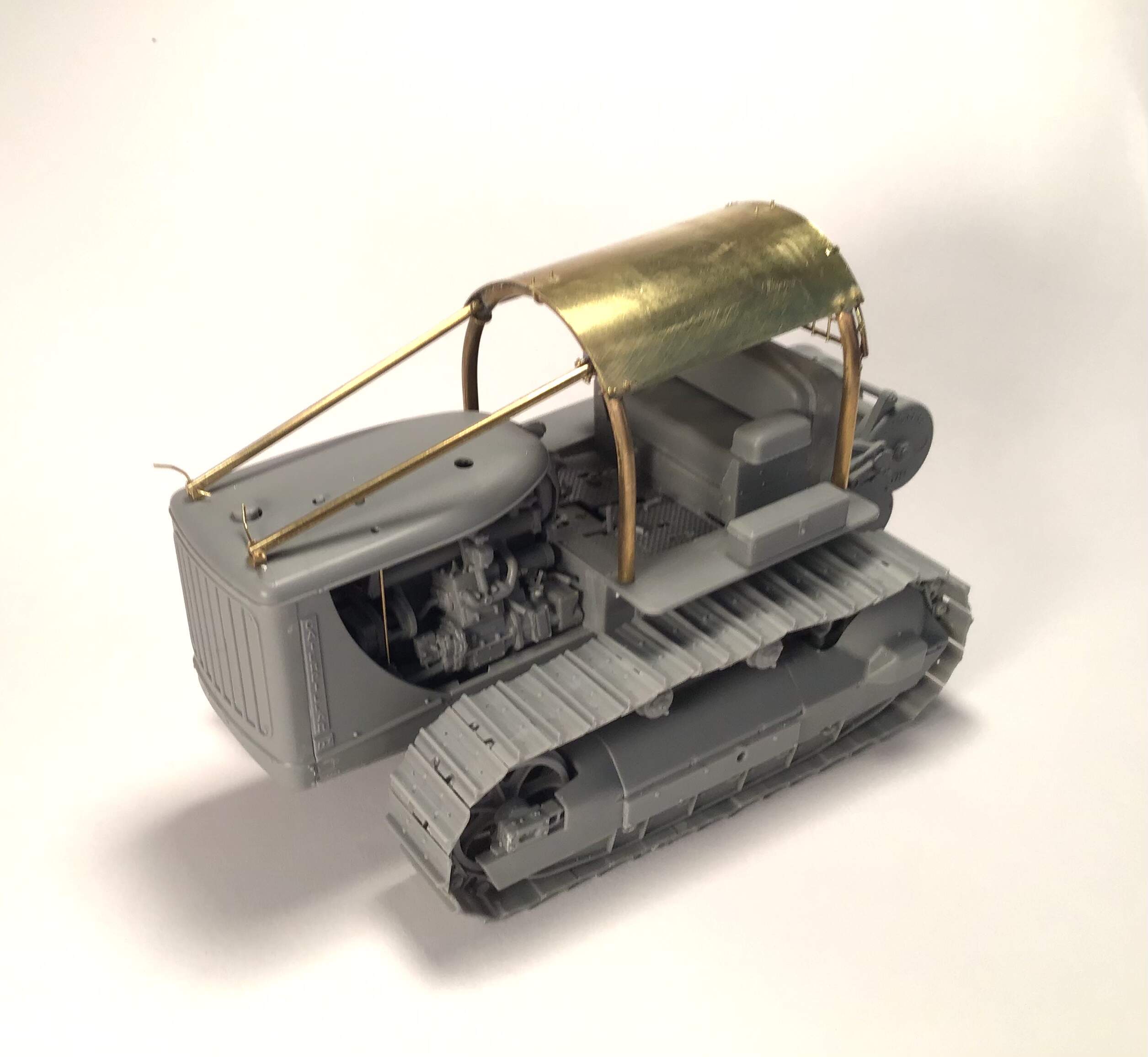

Next up will be figuring out how to fix all the broken levers , pedals etc . All of these parts simply shattered no matter how carefully they were handled. All left a funny core that indicates that the plastic was not heated through during the injection process. I think I may try to fashion new ones out of brass but that still leaves the problem of how to attach them to the stubs that are left- we’ll see…
10 Likes
A little progress - I’ve made up three new levers out of brass to replace the shattered ones . Two steering clutch levers and one main clutch lever.
I flattened some brass rod on the anvil with a hammer and filed a taper on the upper ends . The steering levers were bent to shape and the handles were represented by dipping in Tamiya surfacer.

Brass work in primer now.
That’s about it for the tractor till paint - time to move on to the logging arch. I’m starting to prepare the drawings . Unfortunately the site that had the high resolution pics I saved has lost it’s certification . I am going to email the museum in BC to see if they can take some detail pics for me .
Thanks for looking.
Richard
8 Likes
Work has begun on the logging arch.
Working from the two views given the parts booklet which I previously enlarged to 1/35 scale I made a projection in plan view of the horse shoe shaped main chassis.
The booklet refers to this as the tongue.
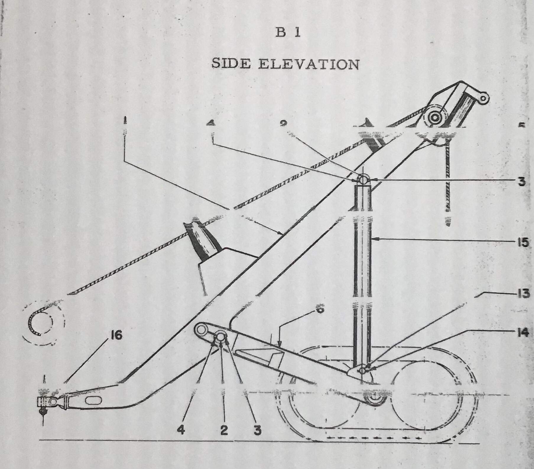
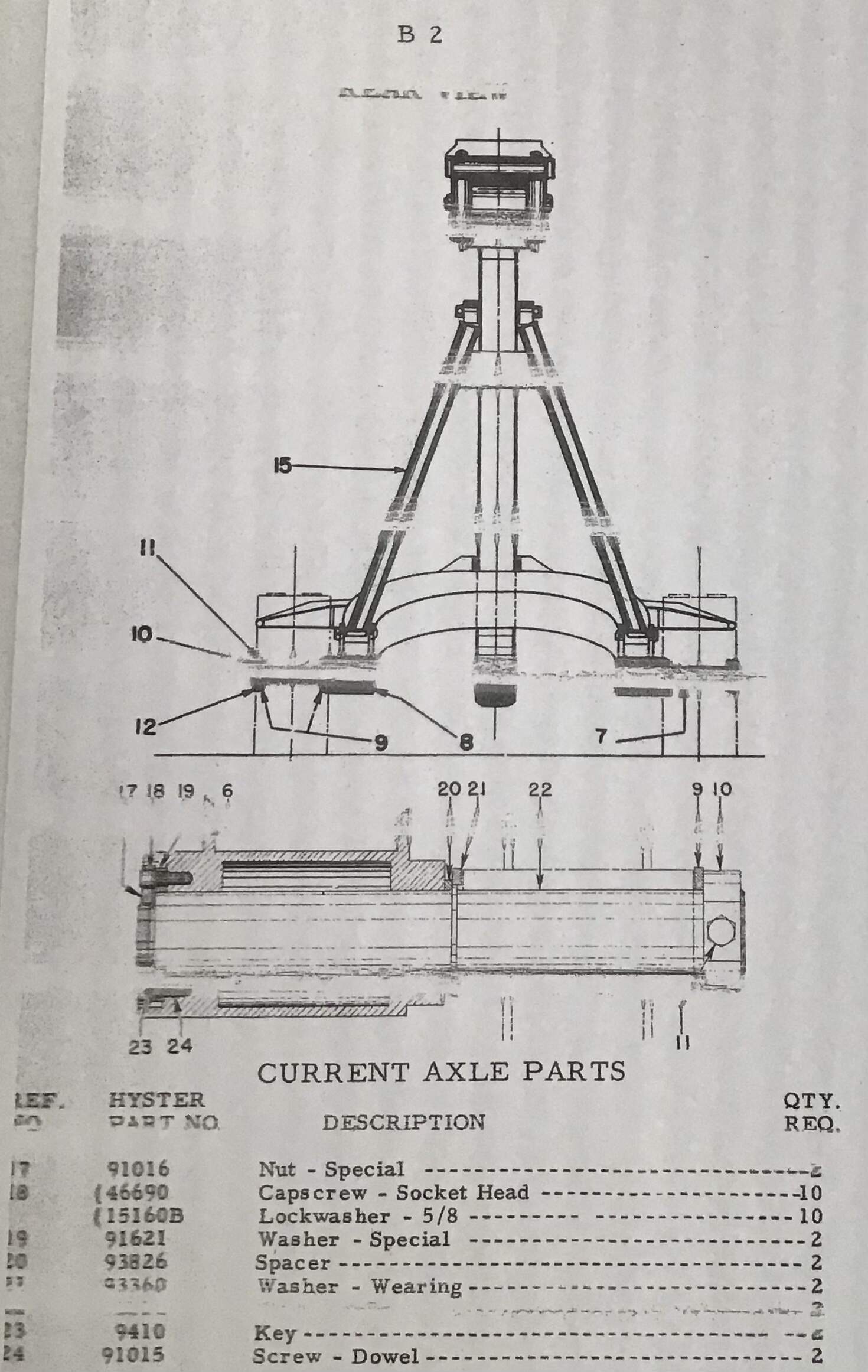

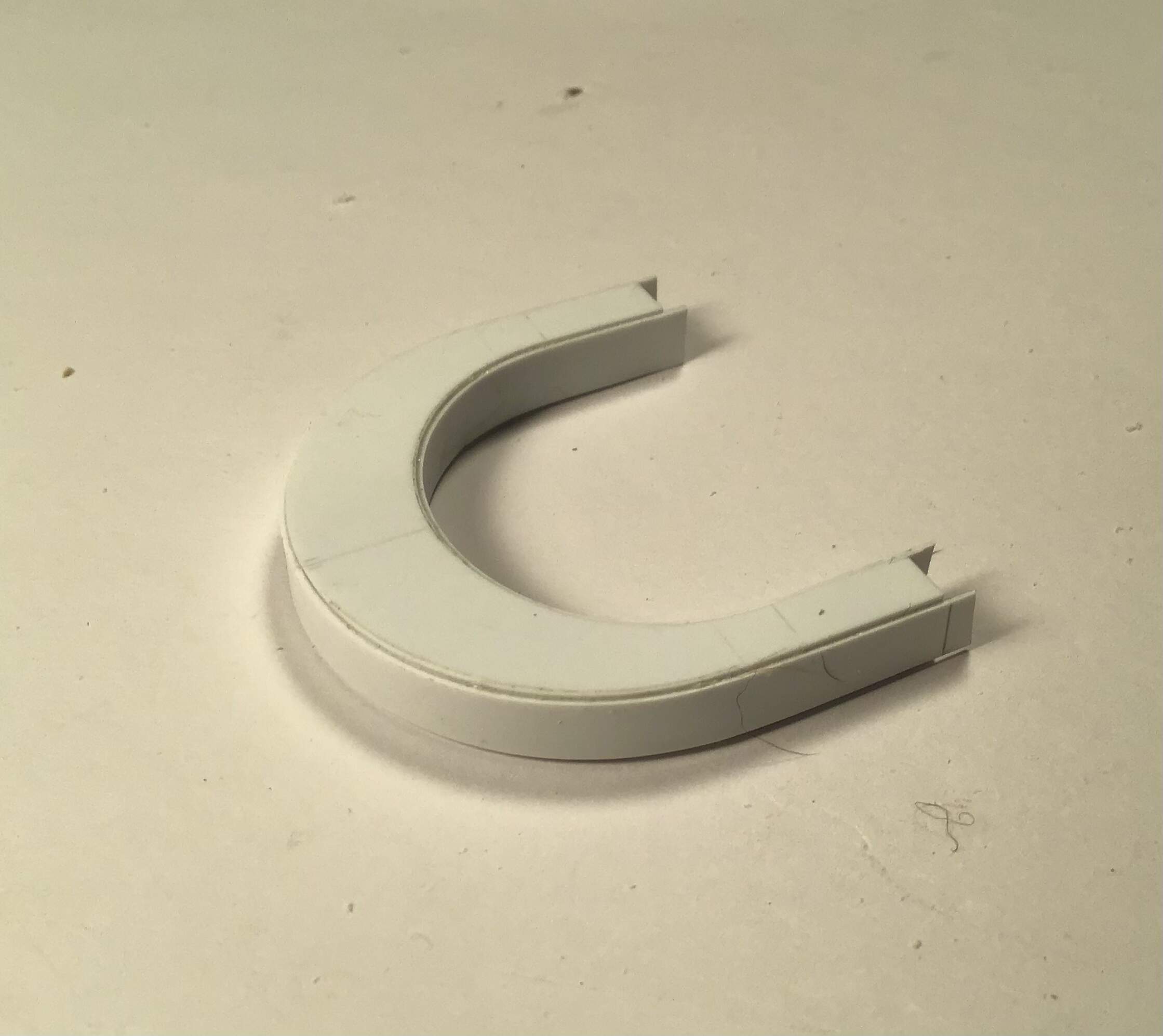
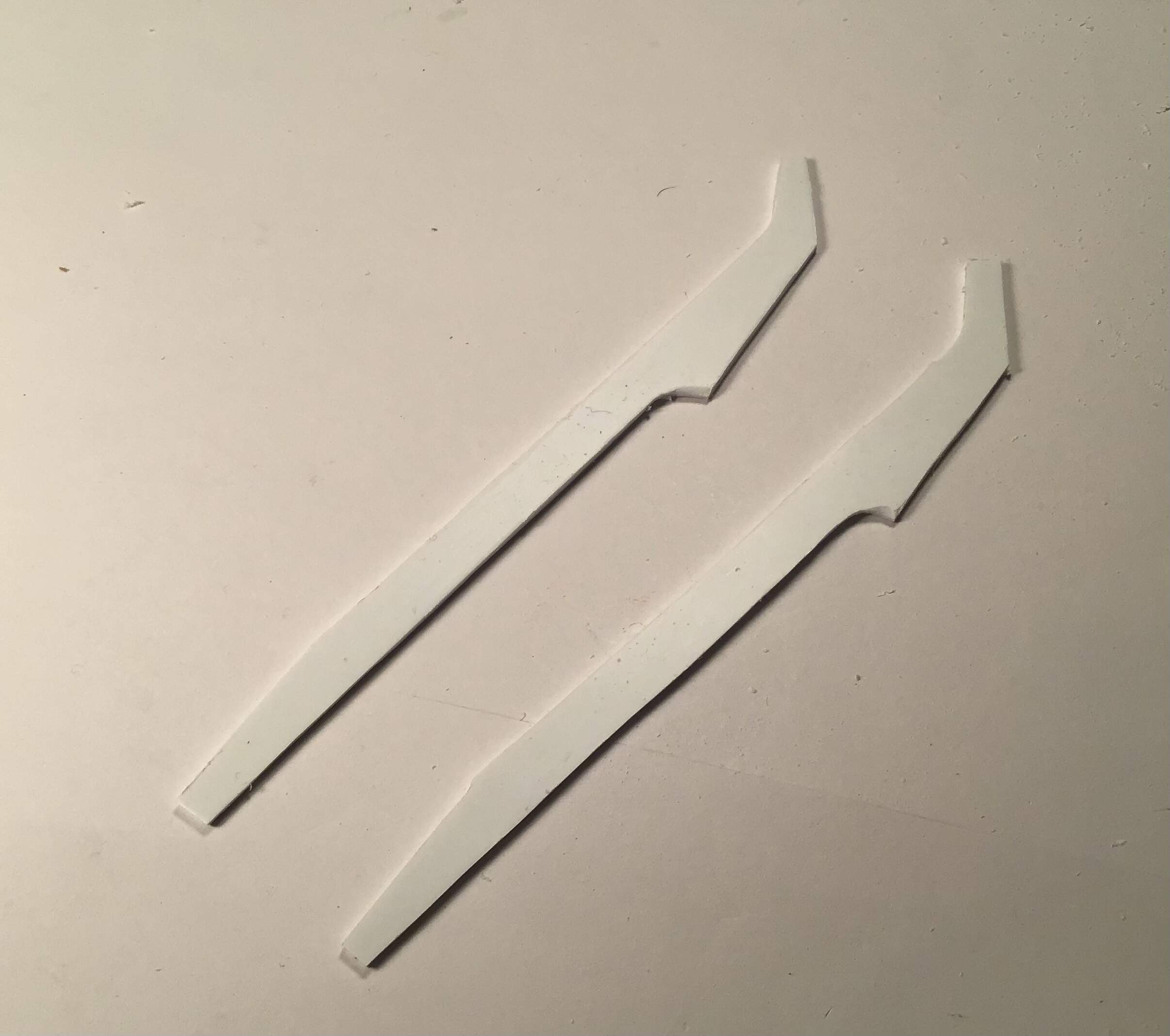
Plan view transferred to sheet styrene and top and bottom cut from sheet . The two parts were taped together with double sided tape and trued up together , then spacer material cut to make up the depth as shown on the side elevation.
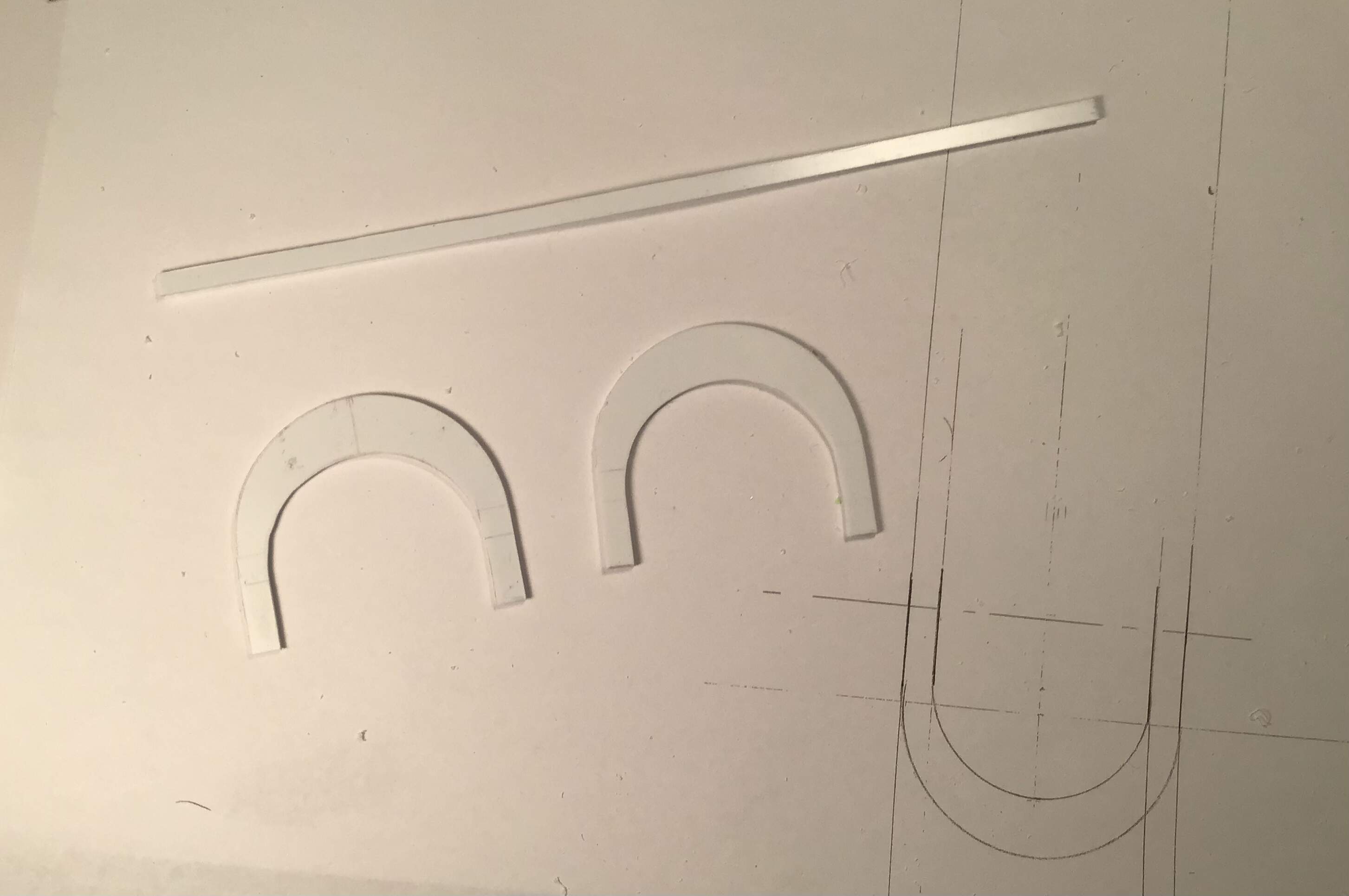
After the two pieces were joined with spacer material the vertical surfaces were faced with thinner sheet styrene to bend around the curved faces . A small rabbet was left top and bottom for the weld seams which will be done with epoxy putty.
The main boom elevation was cut from the drawings and transferred to plastic and two sides roughed out .
The boom will be assembled in the same manner as the chassis ( tongue ? )
Now waiting on some styrene tube stock and hex stock for axle housings , nuts etc.
Thanks for looking !
Cheers- RT
9 Likes
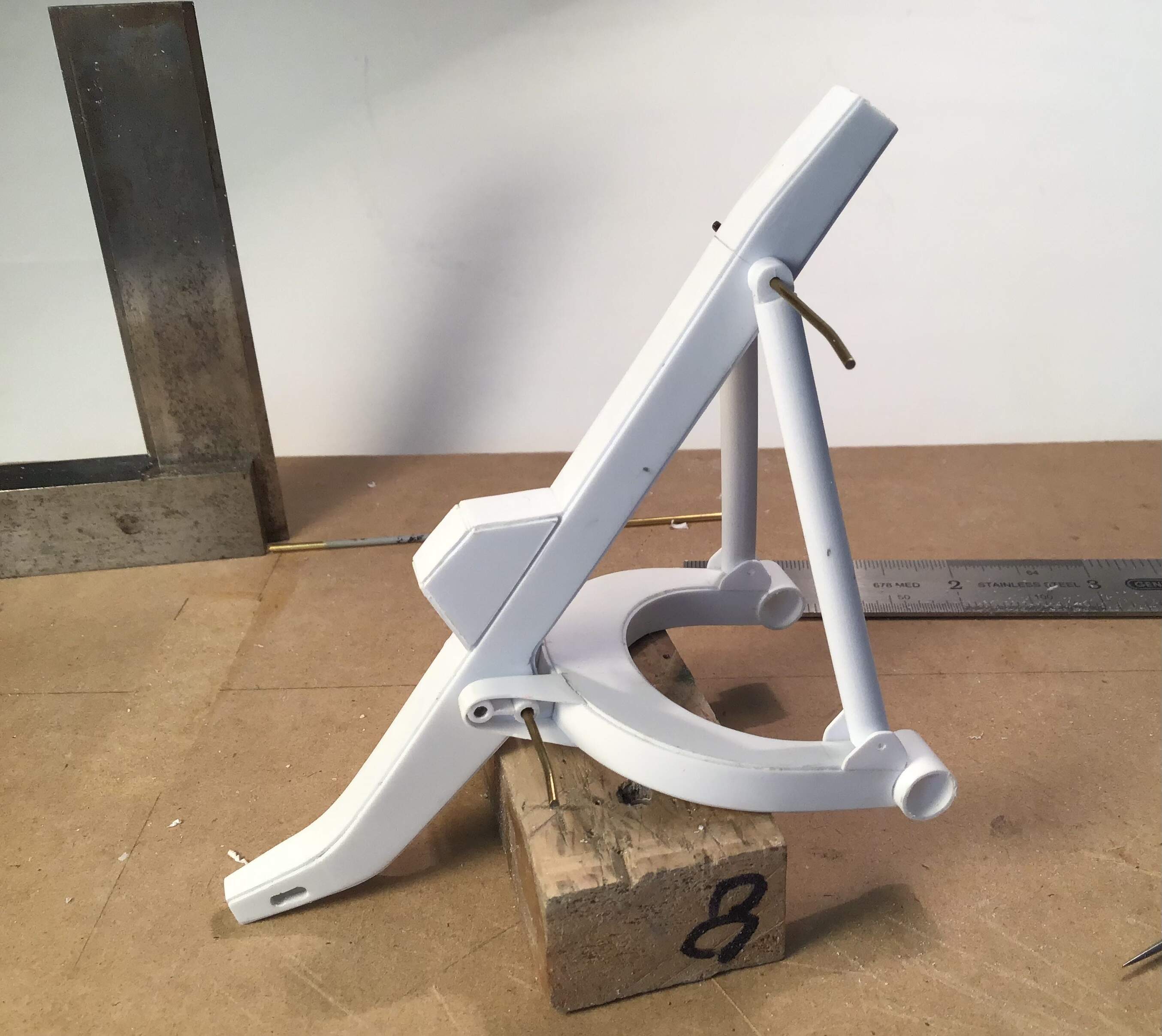
Main boom built up - same technique as chassis / tongue.
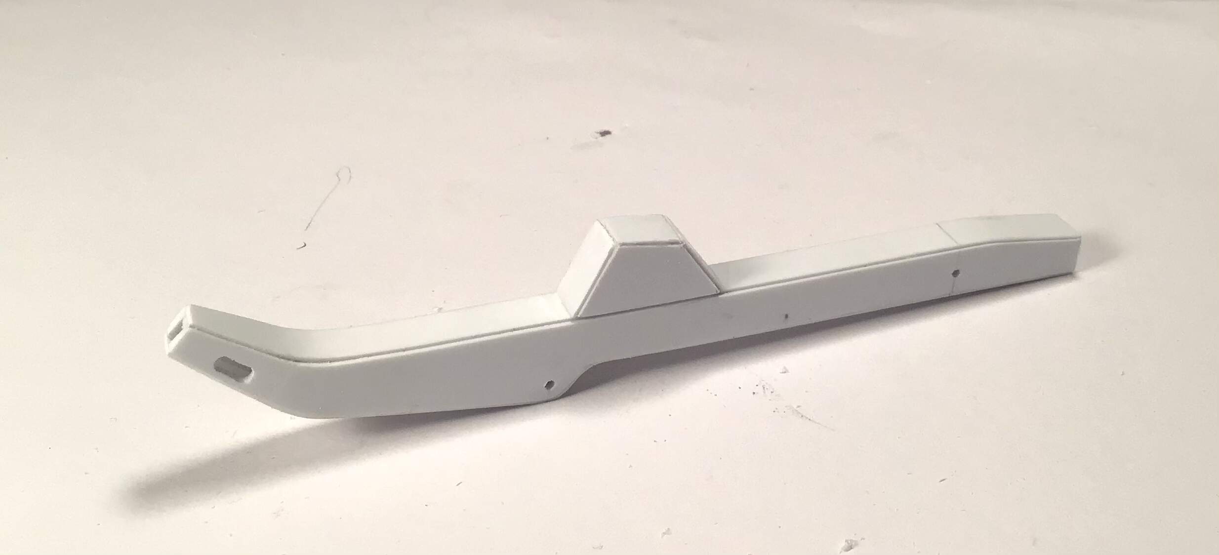
- and the state of the arch components so far …

Waiting on styrene tube and hex rod from Plastruct - just received shipping notification today …
more to come .
10 Likes
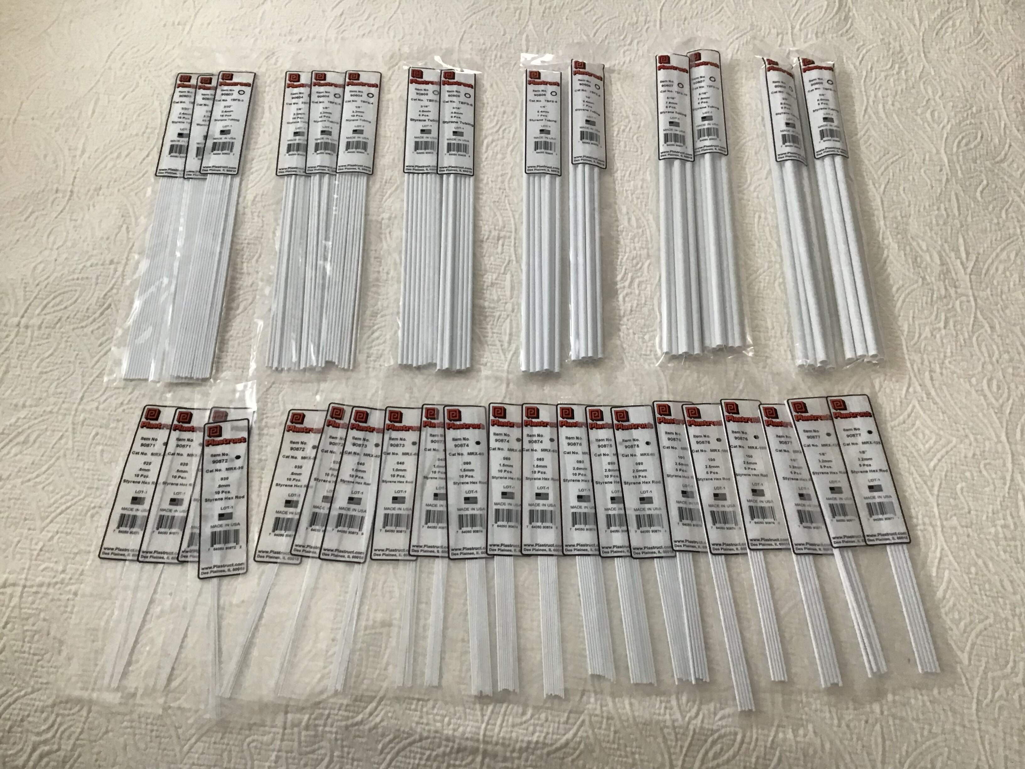
Thanks to the need for meeting the $ 25. minimum order at Plastruct I now have a lifetime supply of styrene hex rod and tubing in all sizes …
While awaiting this material I made up the master for the wheels .
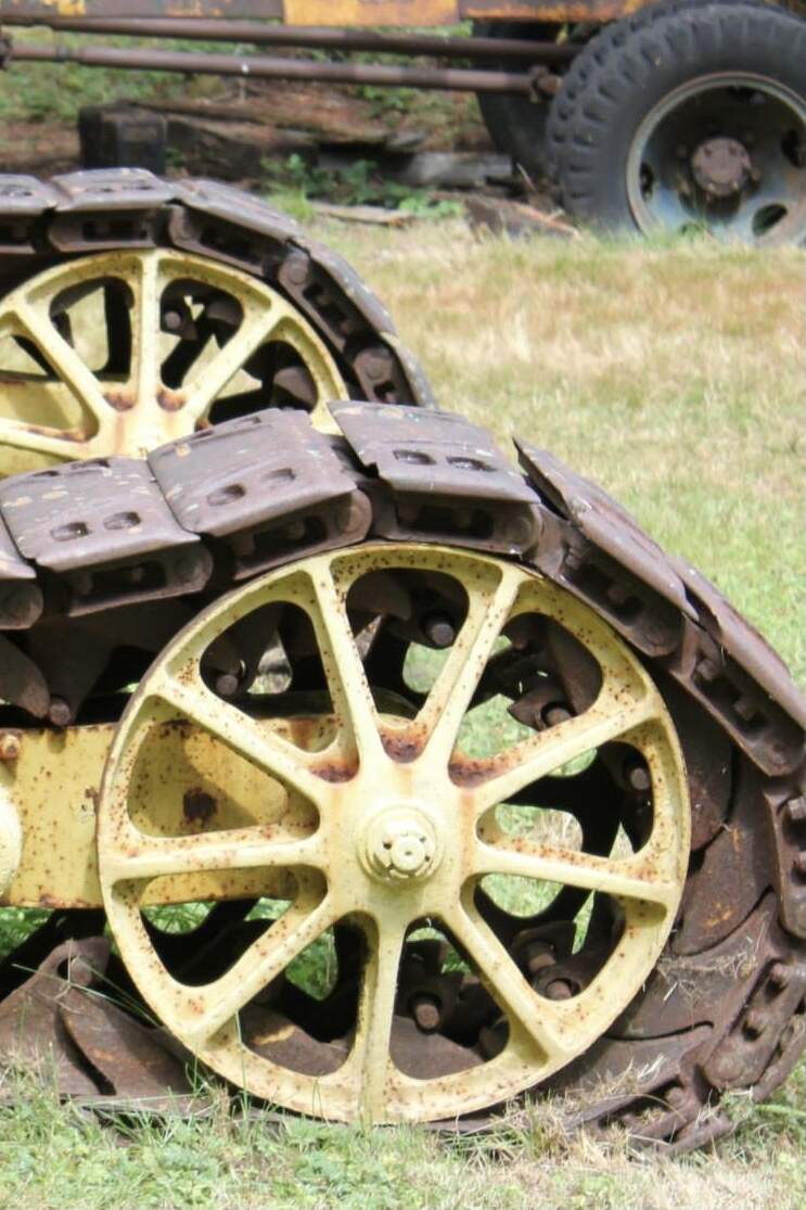
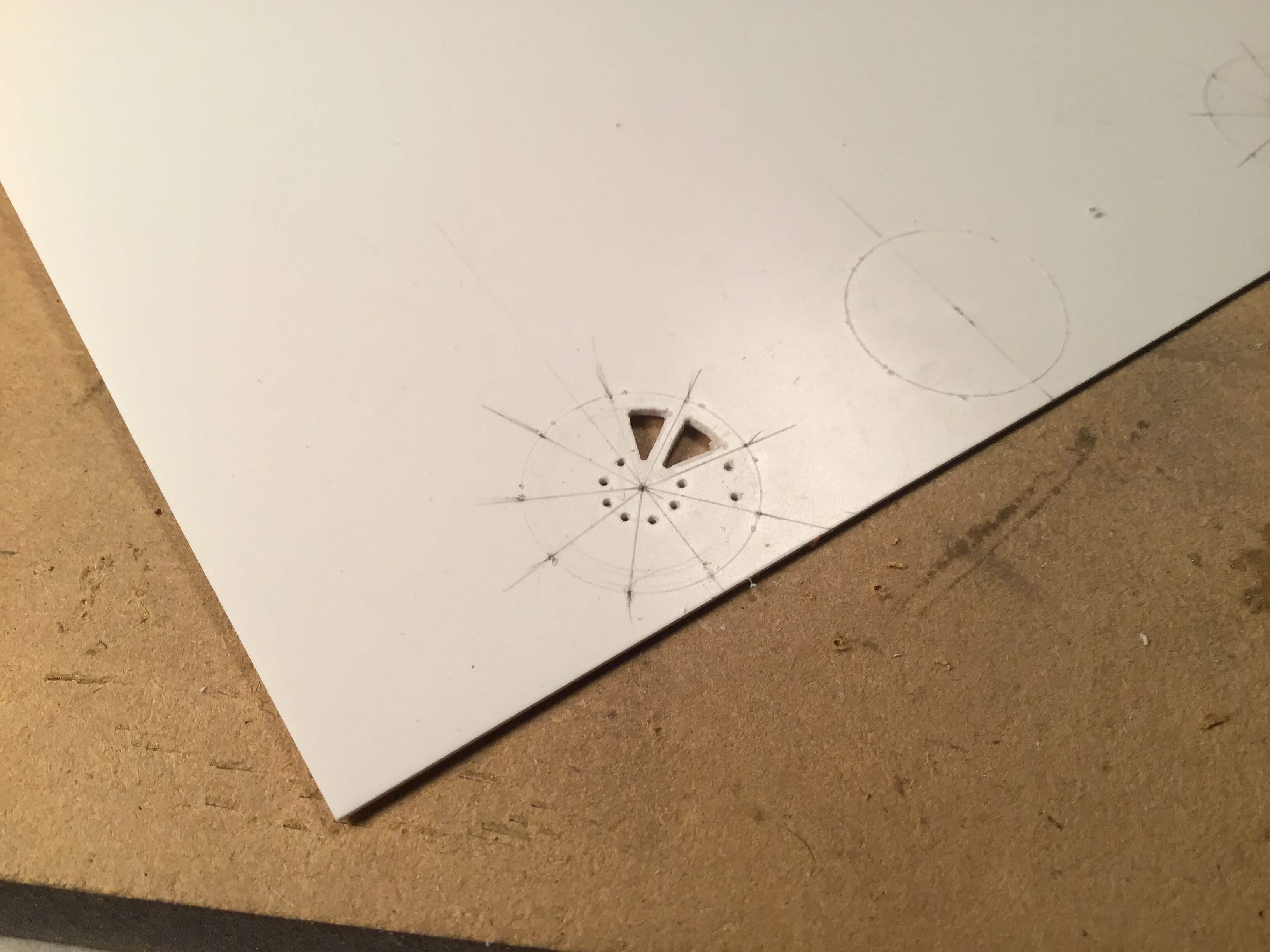
Started by laying out the diameter for the web and dividing it into 9 segments . I laid out the locations for holes at the three corners of the cutouts on a piece of brass shim and marked the holes …
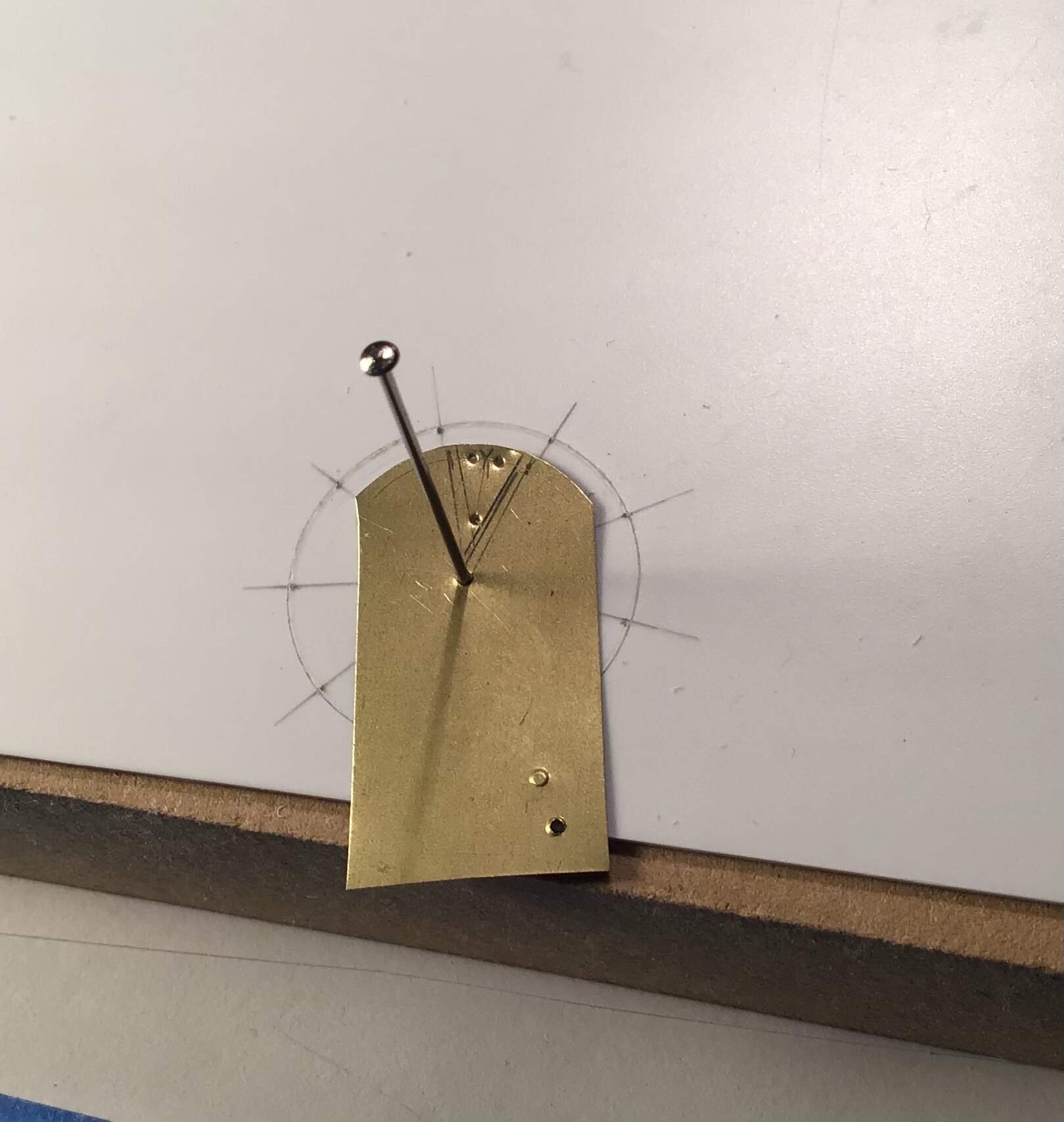
Drilled out the corners and cut out the areas by repeated scoring with a new #11 blade.
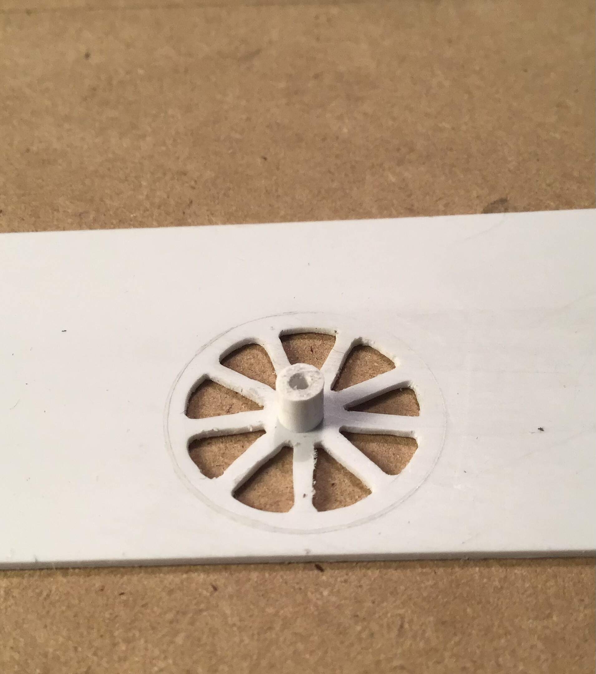
Hub made of 1/8 tube …
… and rim turned out of styrene rod on the lathe.
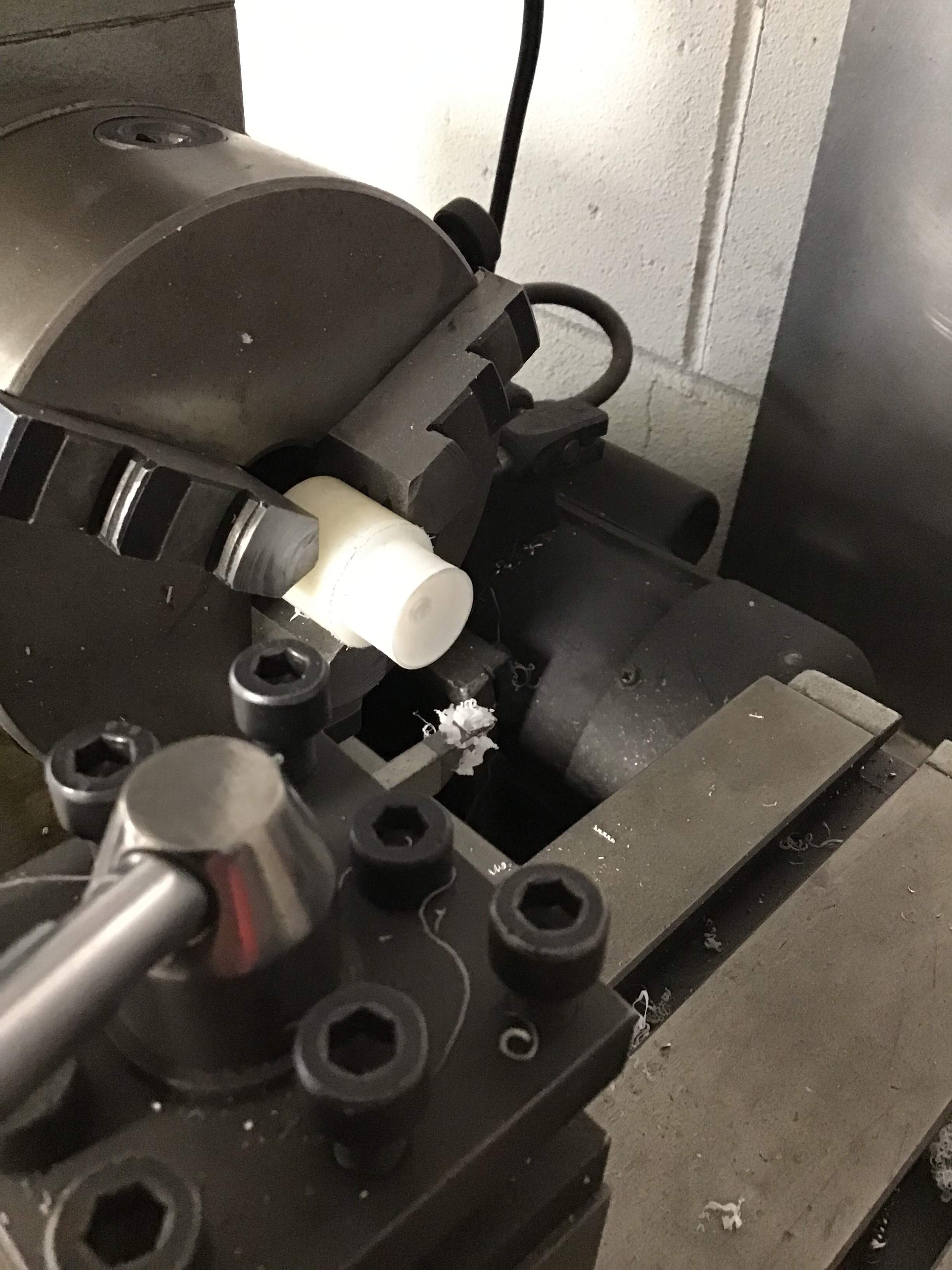
Rim being parted off …
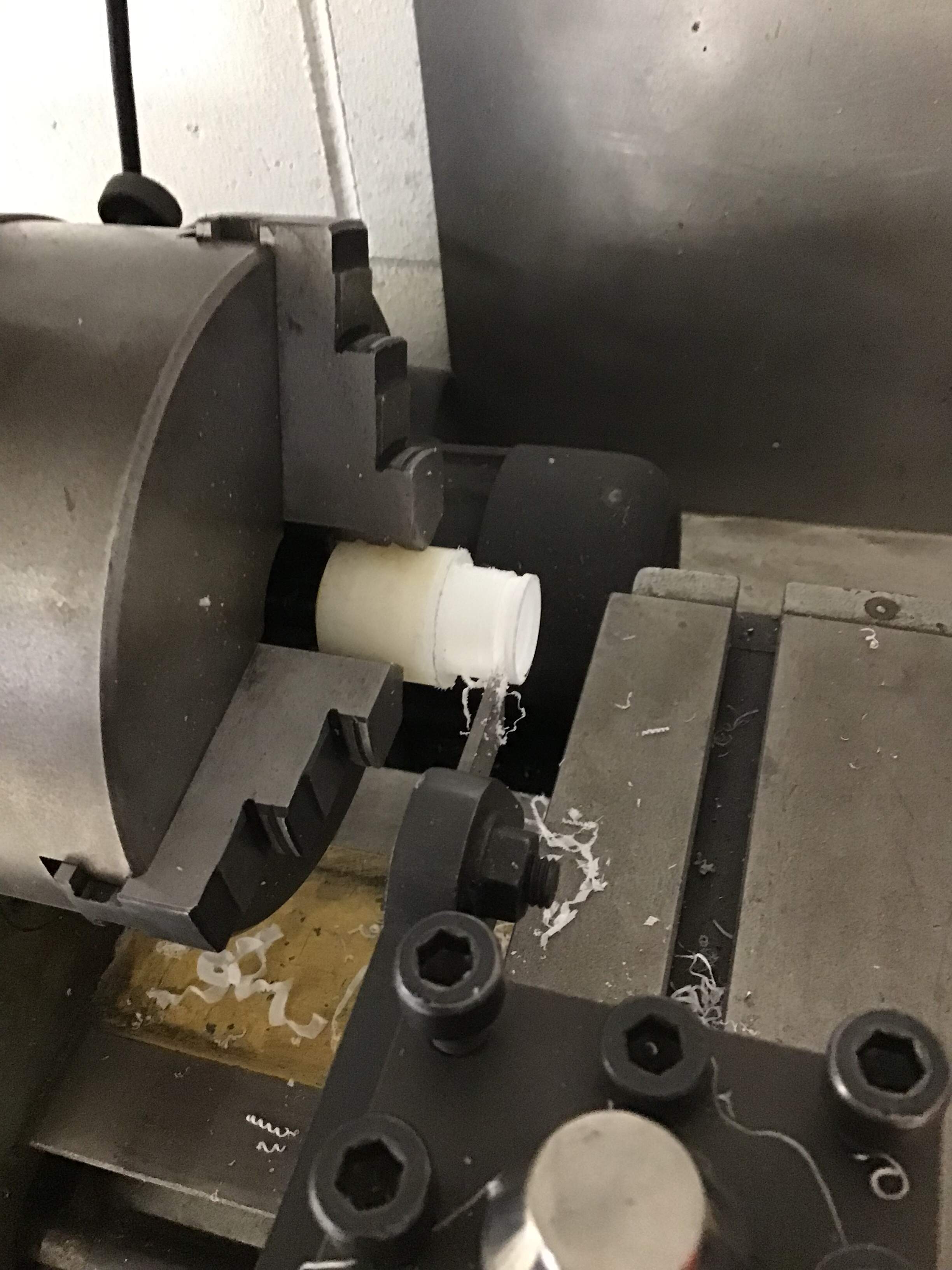
… rim and web …
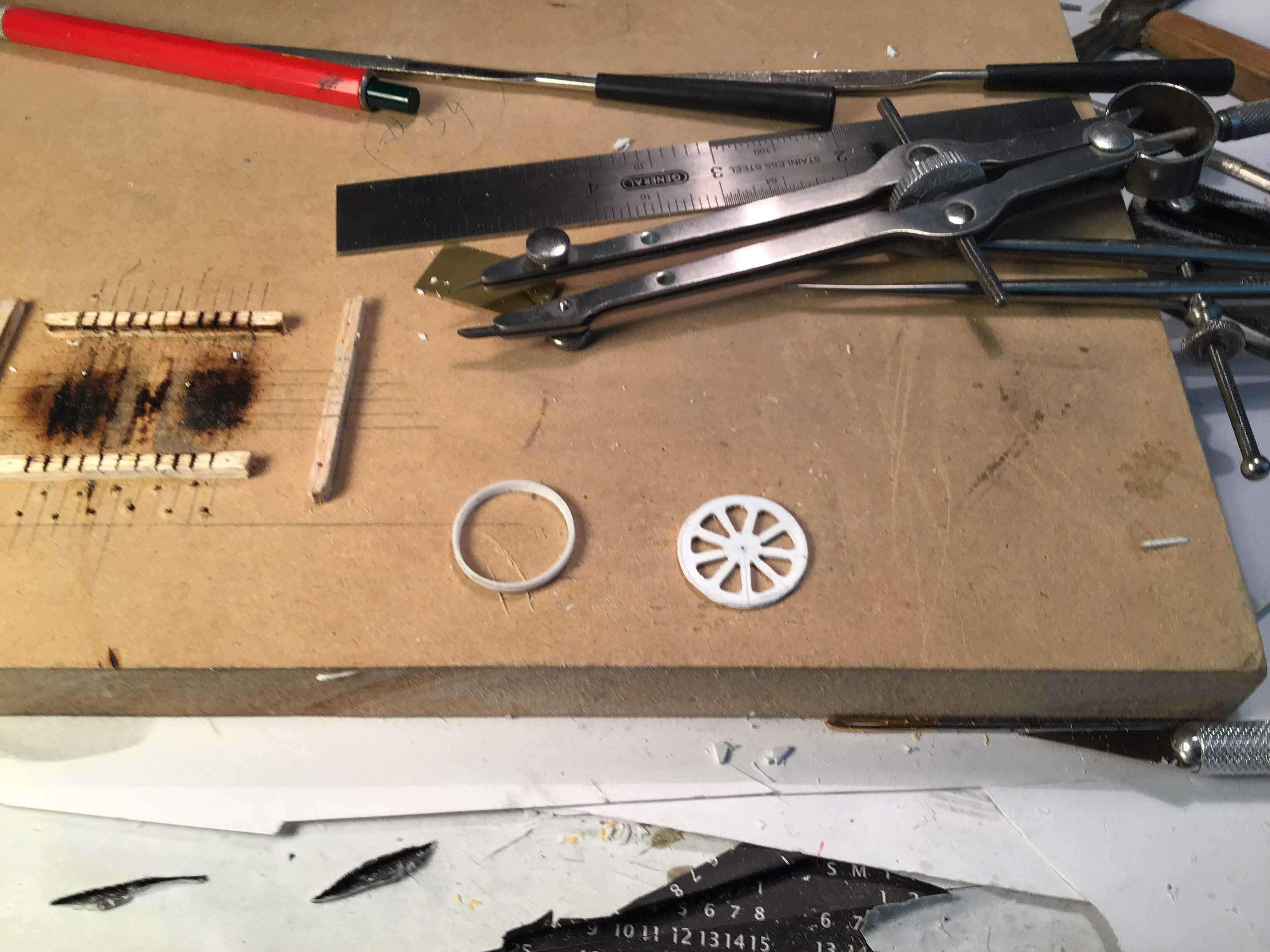
and rim , web , hub and radial spoke webs assembled.
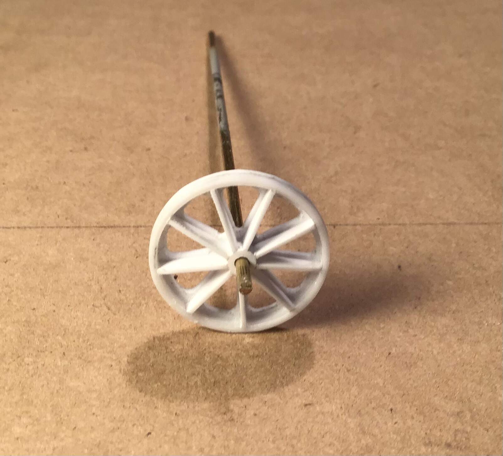
Now awaiting epoxy putty to make up the fillets between the spokes at hub and rim .
Thanks for looking and as always, all comments welcome.
Cheers-RT
14 Likes
Once again, incredible work! Excellent!
3 Likes
You sir; are an artisan… Outstanding work.
4 Likes
- and all others - Thanks for the interest and compliments . Really enjoying this project.
Thanks again - Richard
3 Likes
Short update but a lot of progress.
Links and axle tubes on main chassis ( tongue ? )
built up.
Boom struts and brackets made .
The boom struts are oval in section. These were made by immersing round tube in boiling water for a minute or two then compressing between the jaws of a bench vise . The banding around the chassis to boom links were also thermoformed by immersion and bending around a piece of brass rod.
Next up will be weld beads on boom and chassis.
Thanks- RT
11 Likes