That looks great. ![]()
![]()
2 Likes
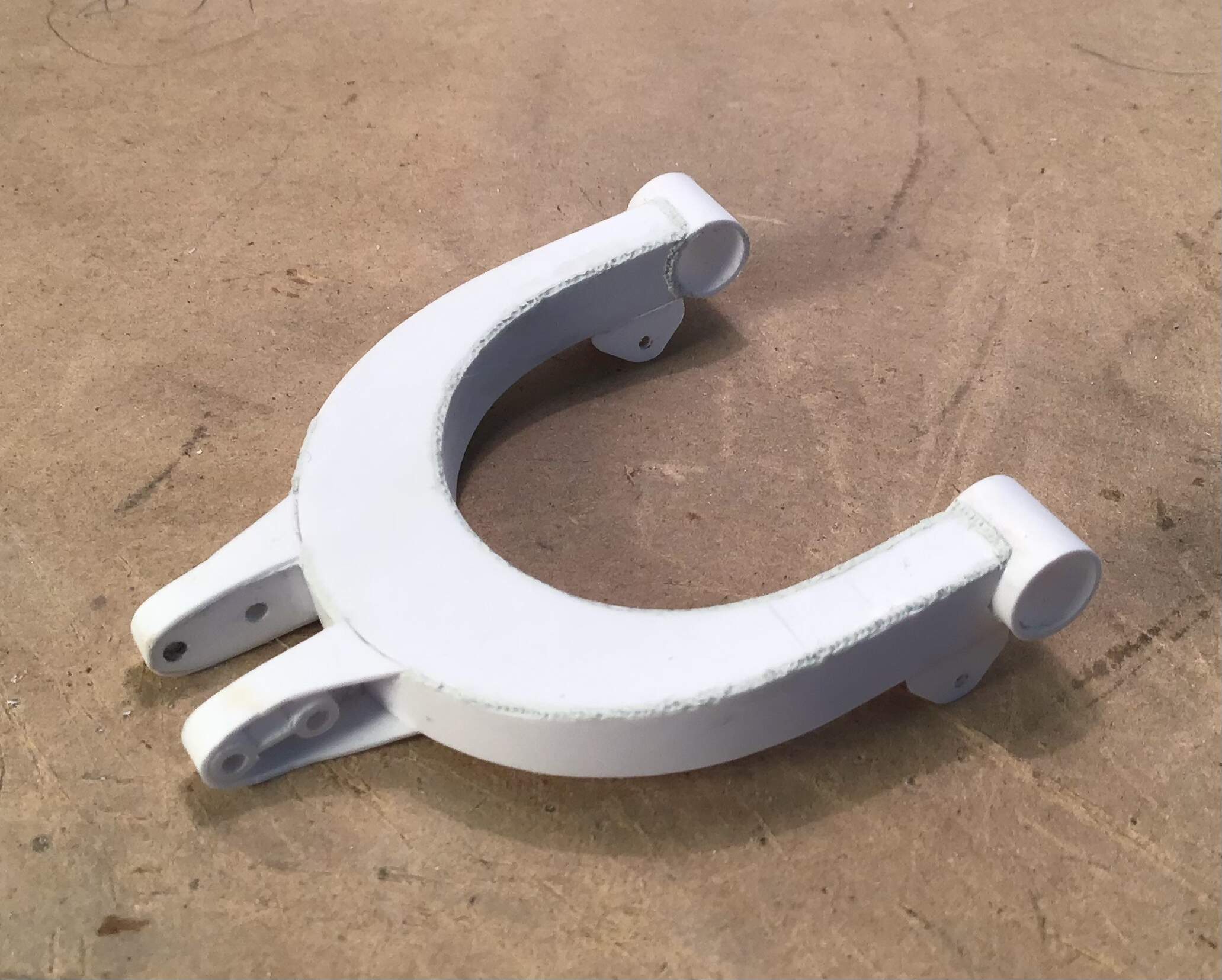
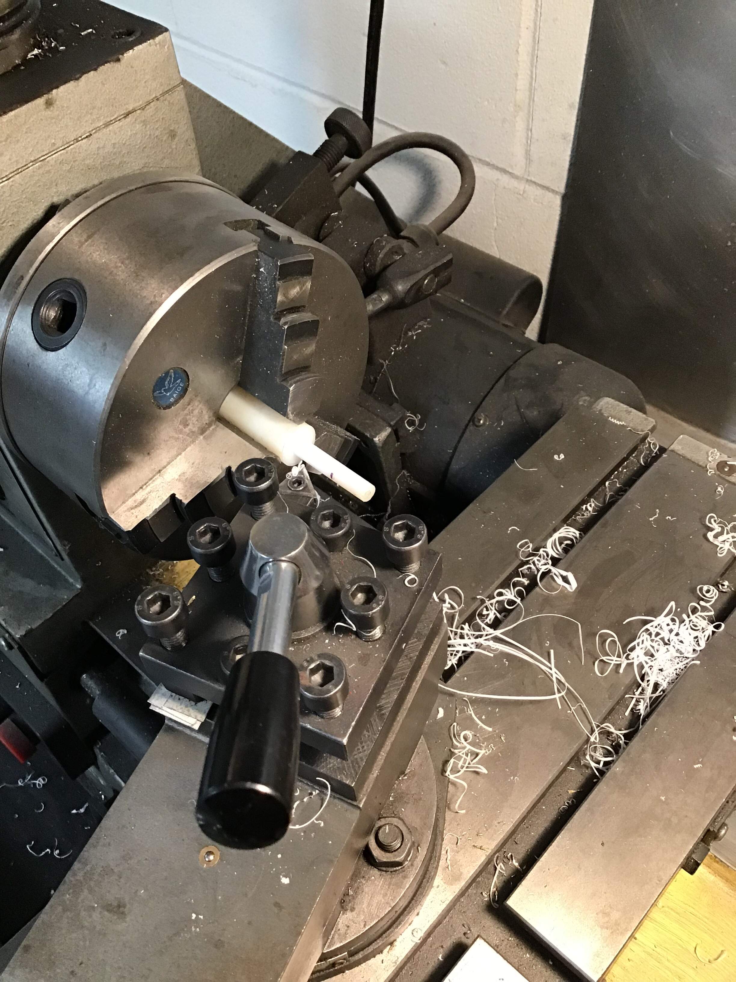
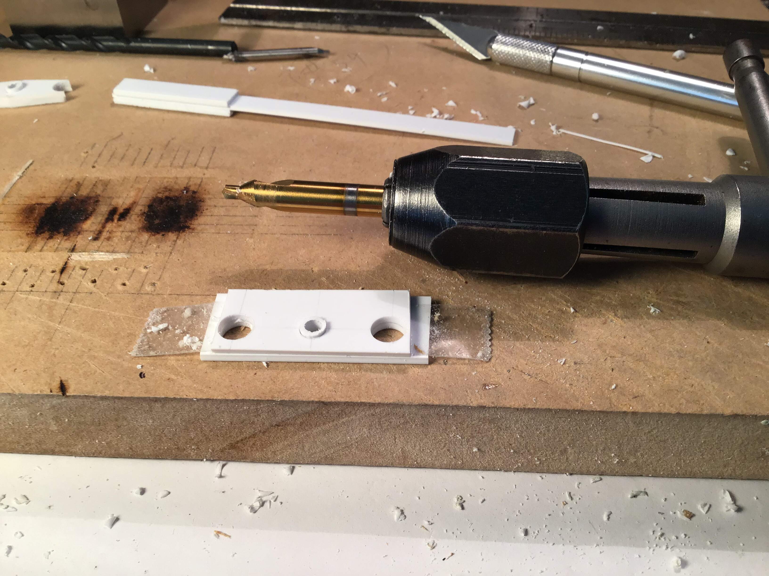
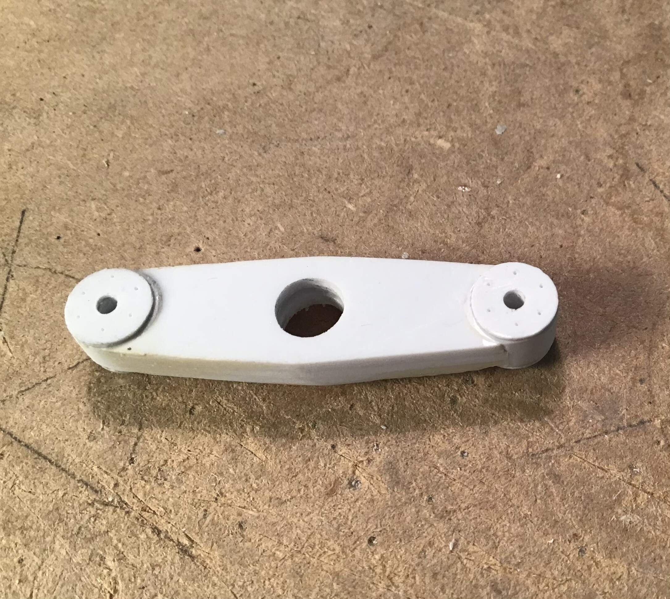
Built up the roller / fairlead system for the end of the boom -

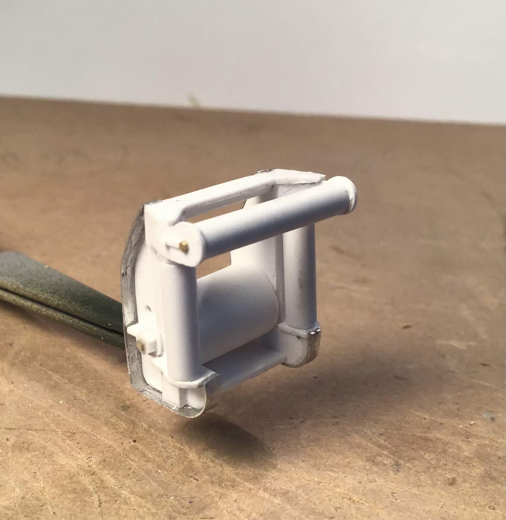
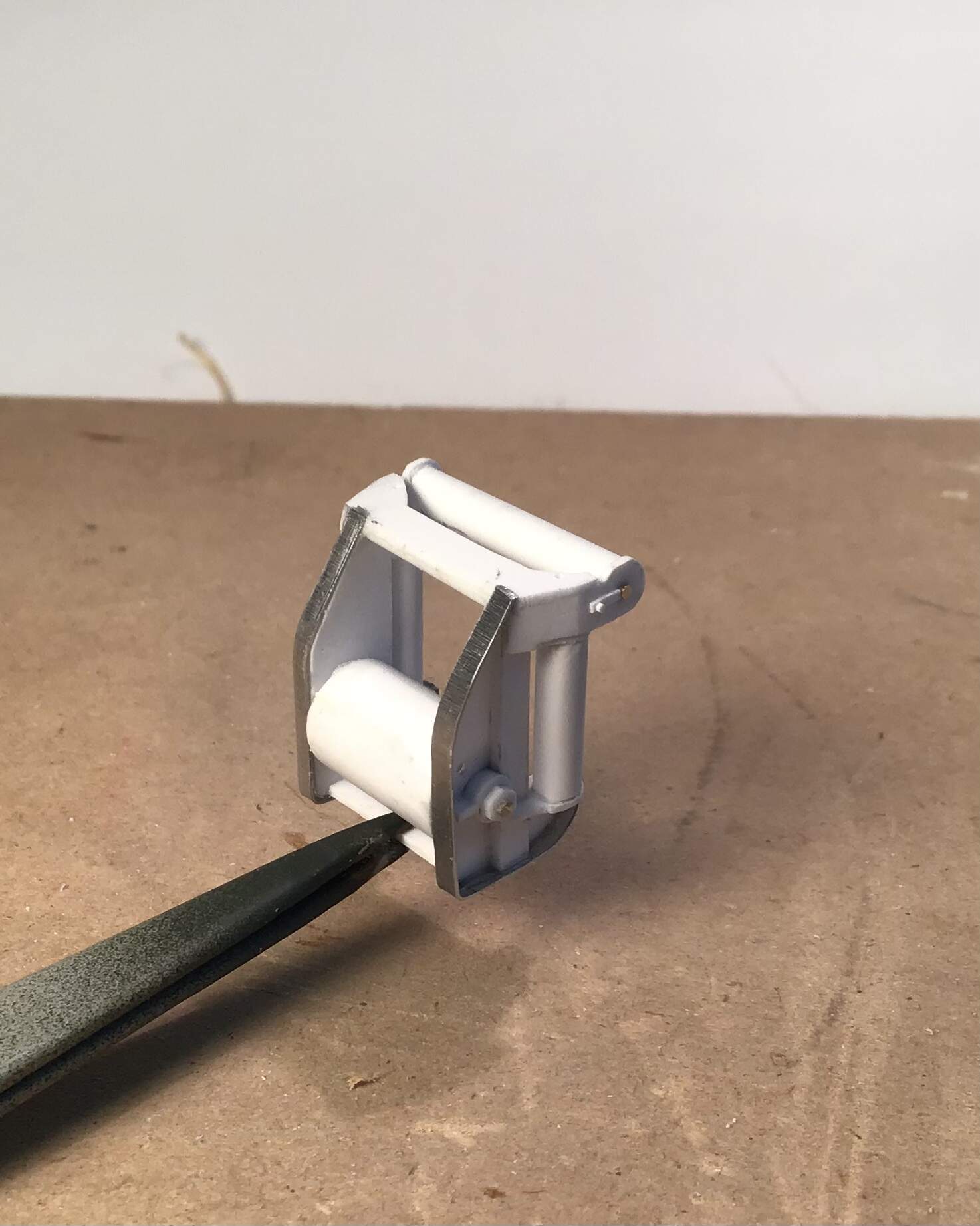
I had to use aluminum for the banding around the cheeks as I had no brass of the appropriate thickness and styrene kept failing at the bends once the cement hit it . The aluminum was fastened with epoxy. The roller system will be permanently installed on the boom after I do some of the weld beads and make up the two cable guides for the boom.
Weld beads begun on the main chassis.
16 Likes
Loving this build.
4 Likes
Just keeps getting better and better. Keep it up. ![]()
![]()
3 Likes
@petbat
@Tank_1812
Thanks all for the interest and kind words.
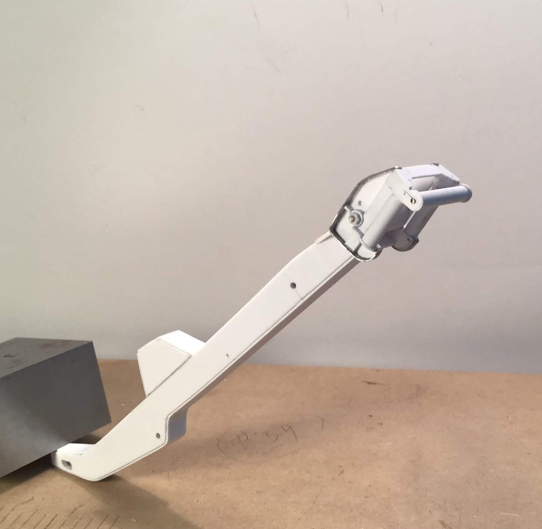
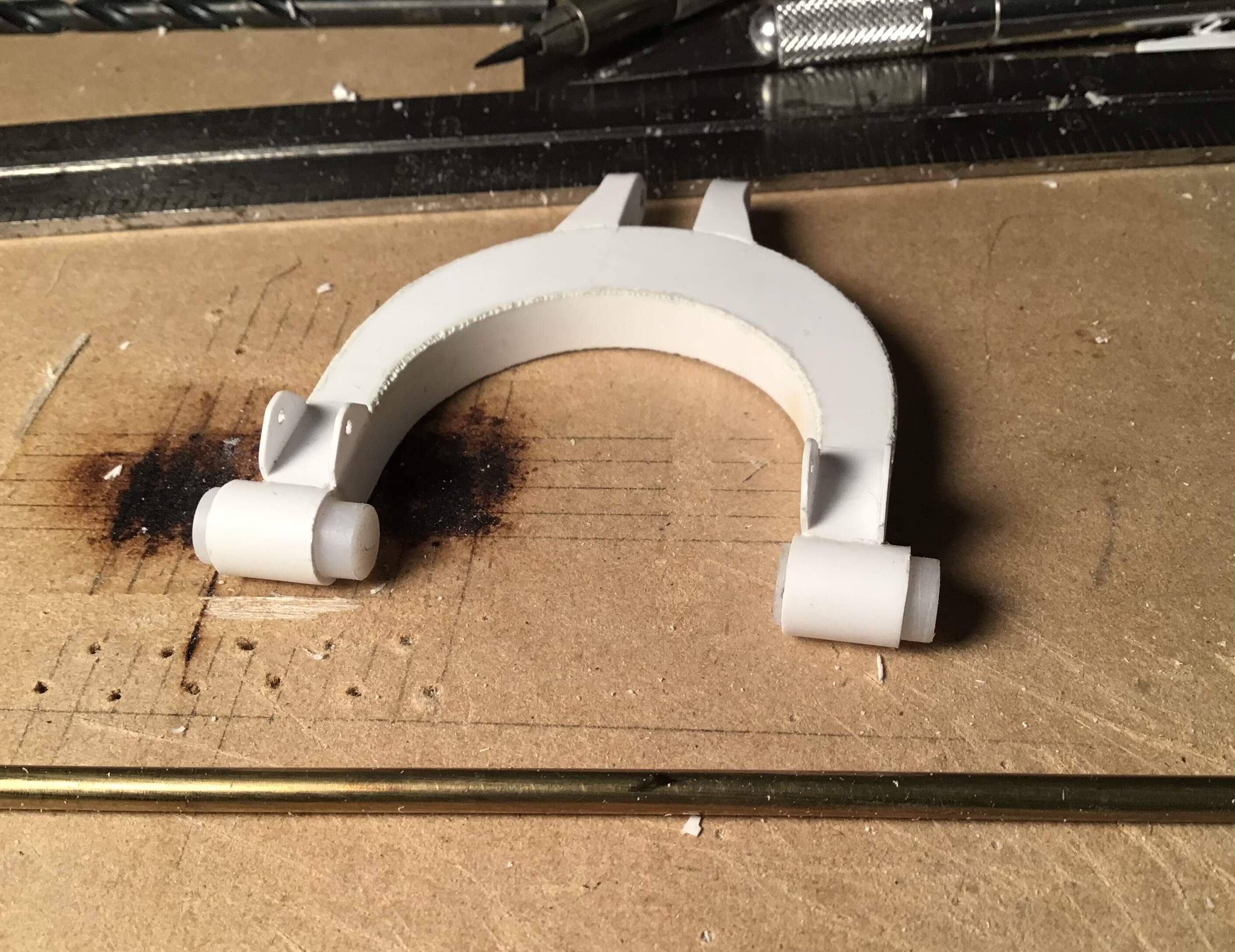
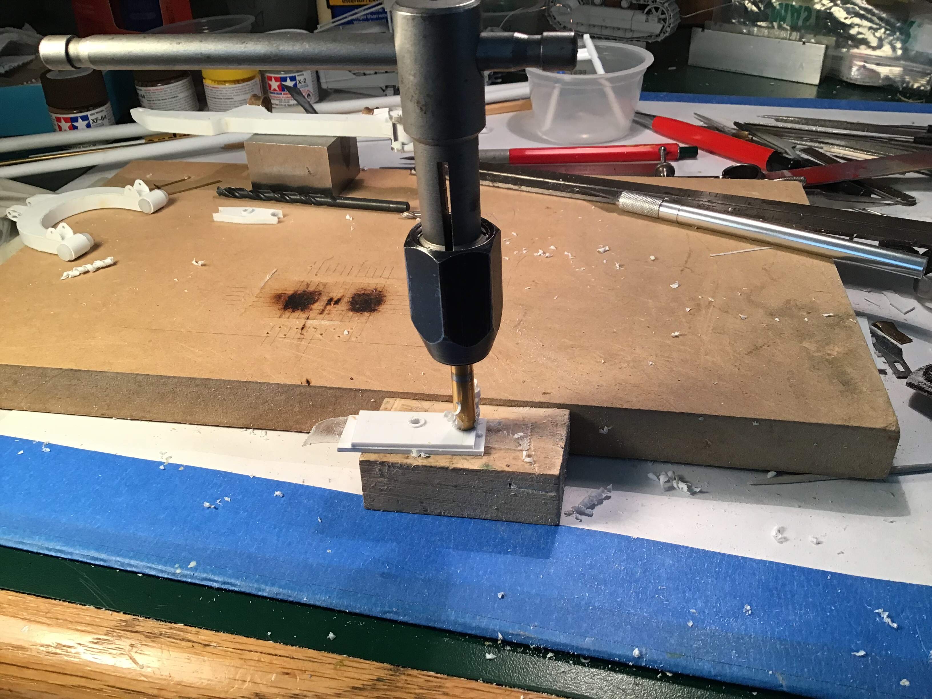
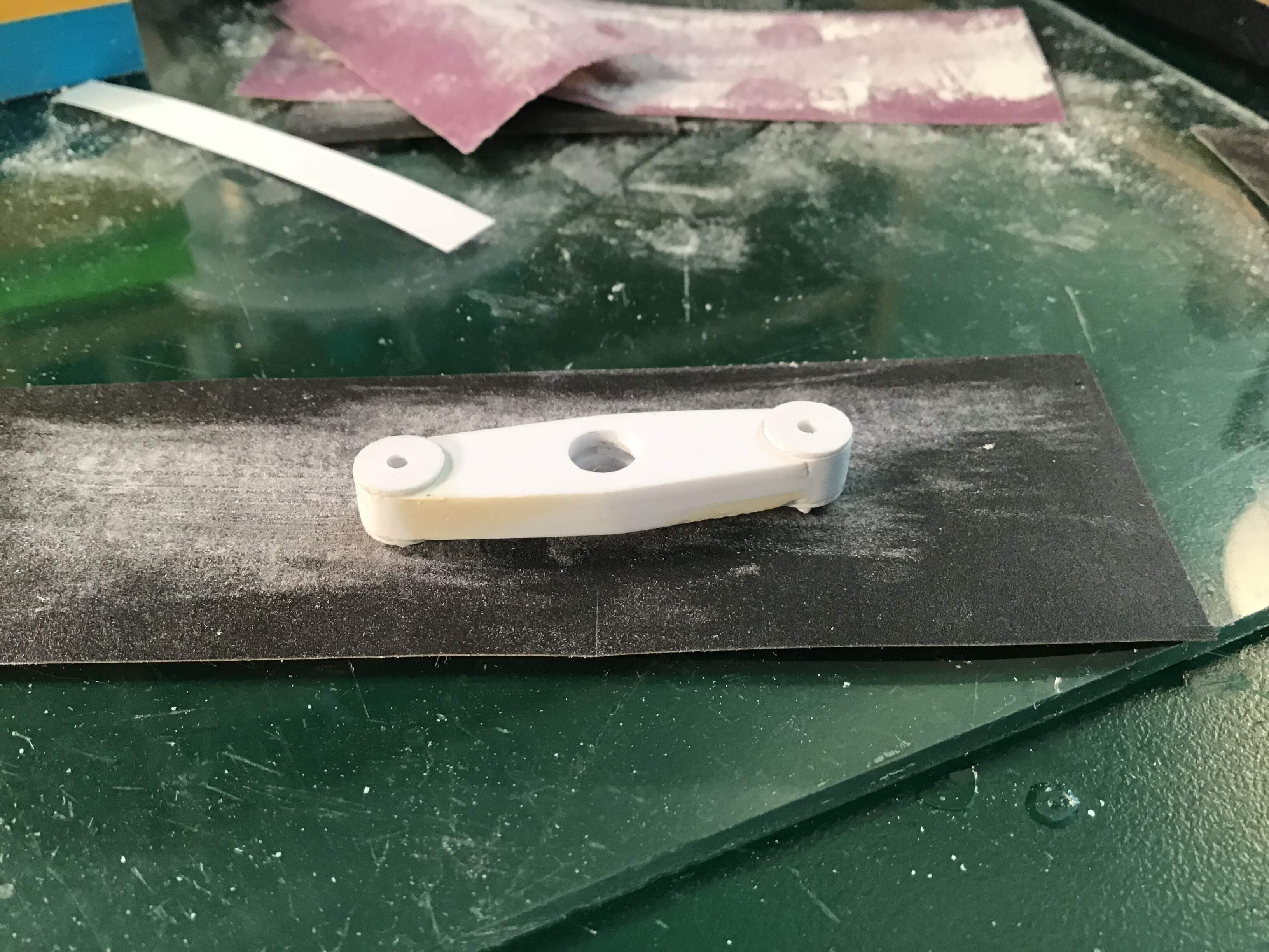
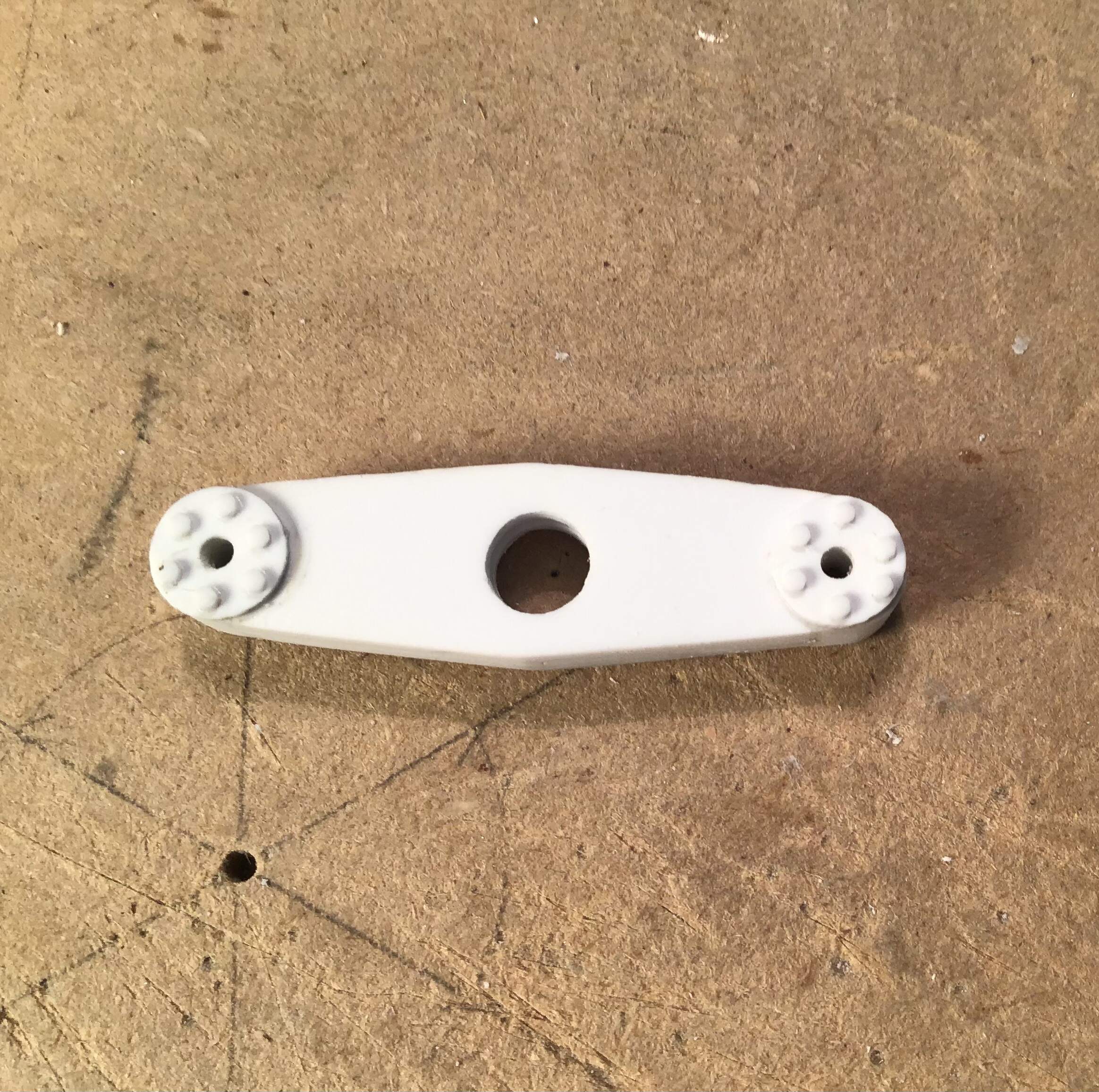
Moving on to the cable guides for the boom .
Marked off the width on brass sheet with a pair of dividers. I filed one point to a chisel shape for this .
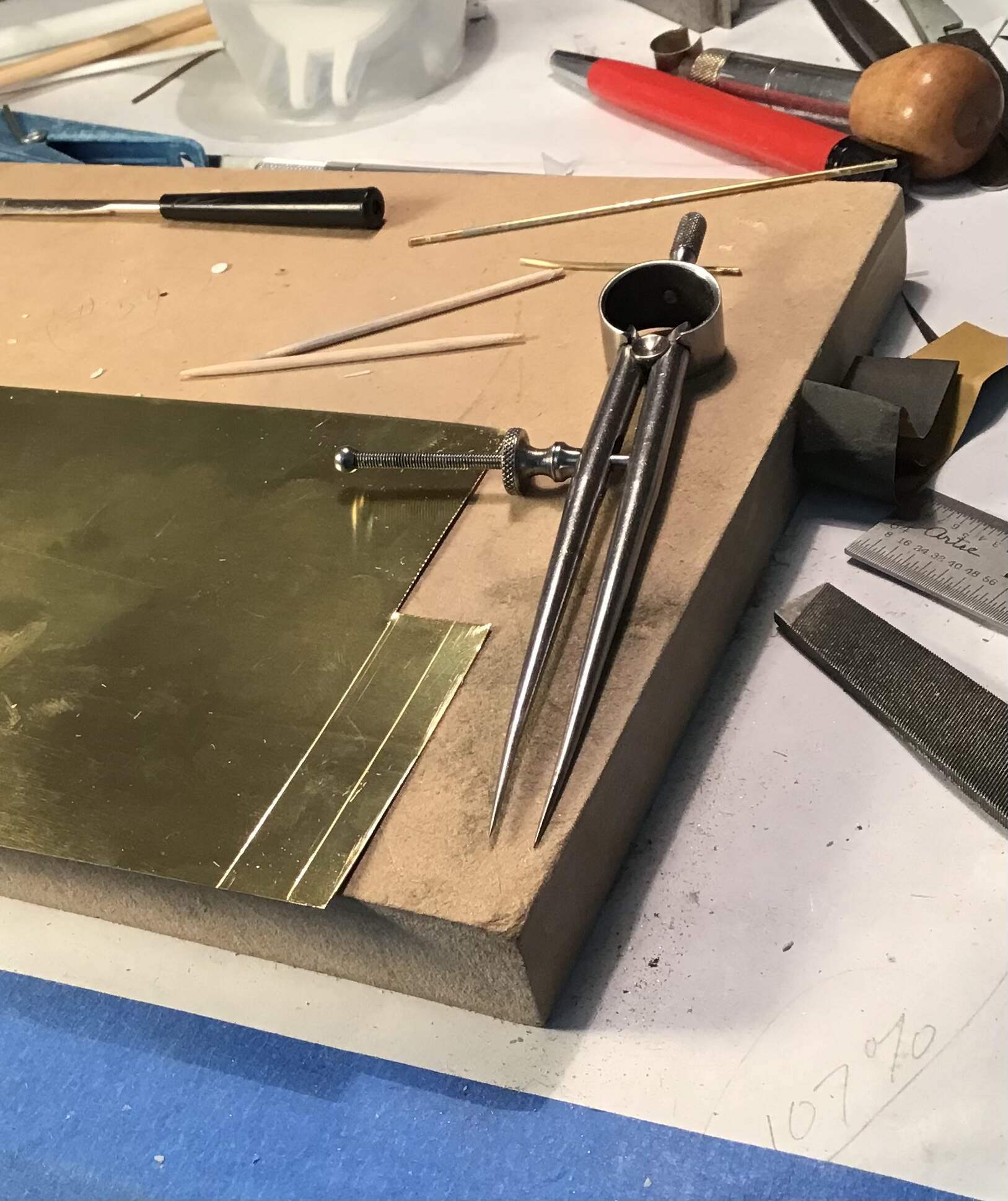
Strip cut off with scissors-
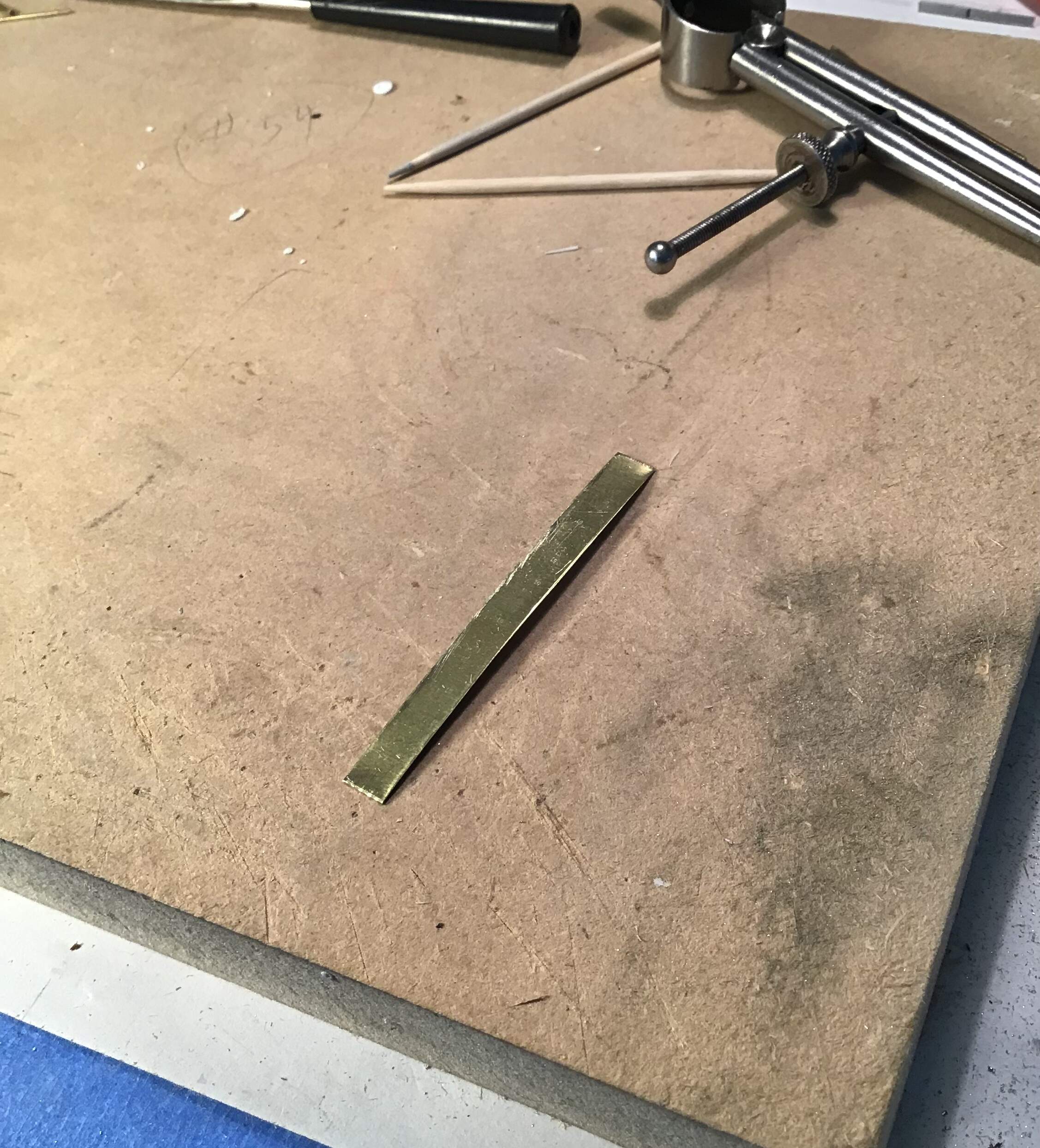
Strip bent around drill bits to form a loop while in hard state -
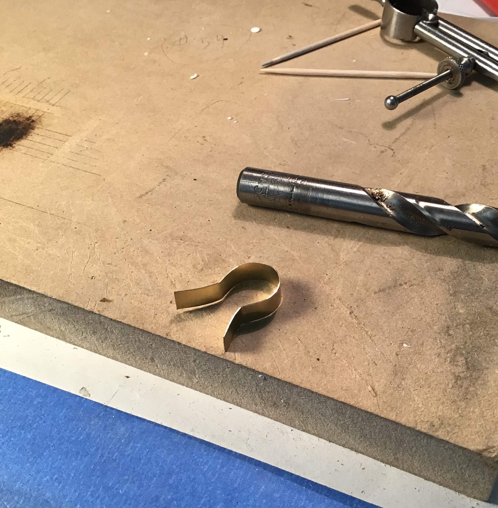
Loop annealed with torch -
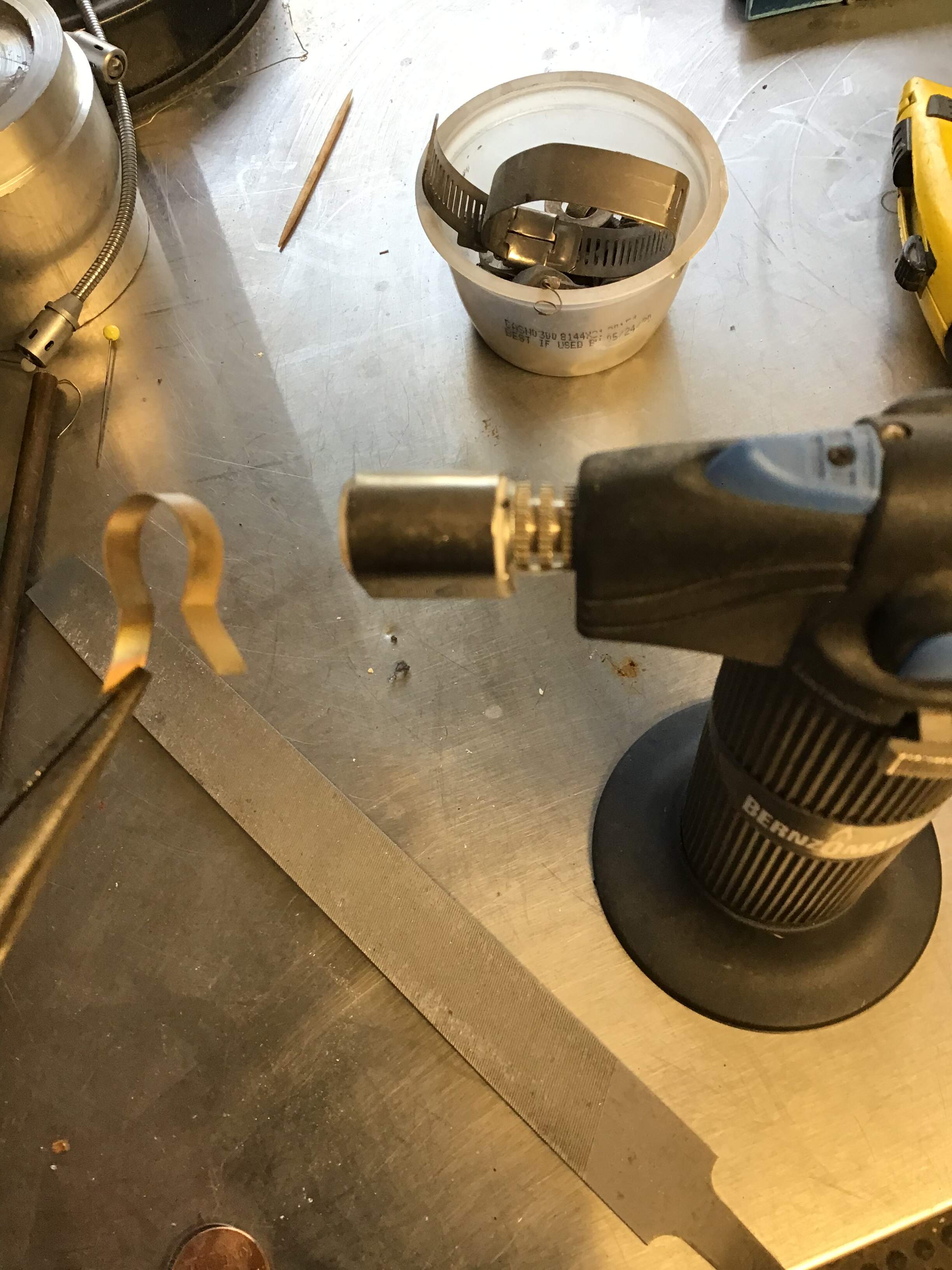
Buck made of wood by creating open ended hole of appropriate diameter and easing corners with a radius bit -
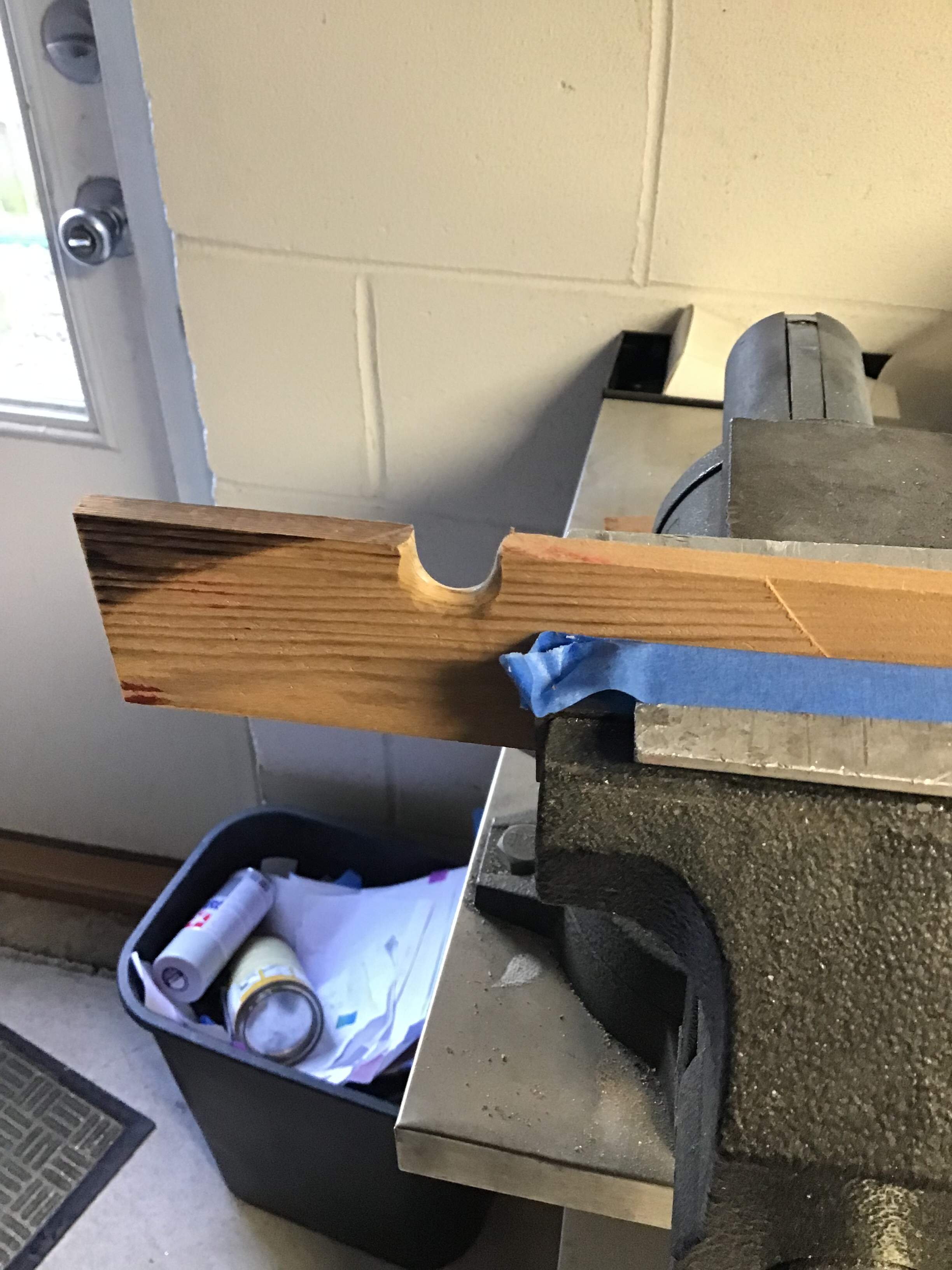
Loop formed over buck with ball peen hammer-
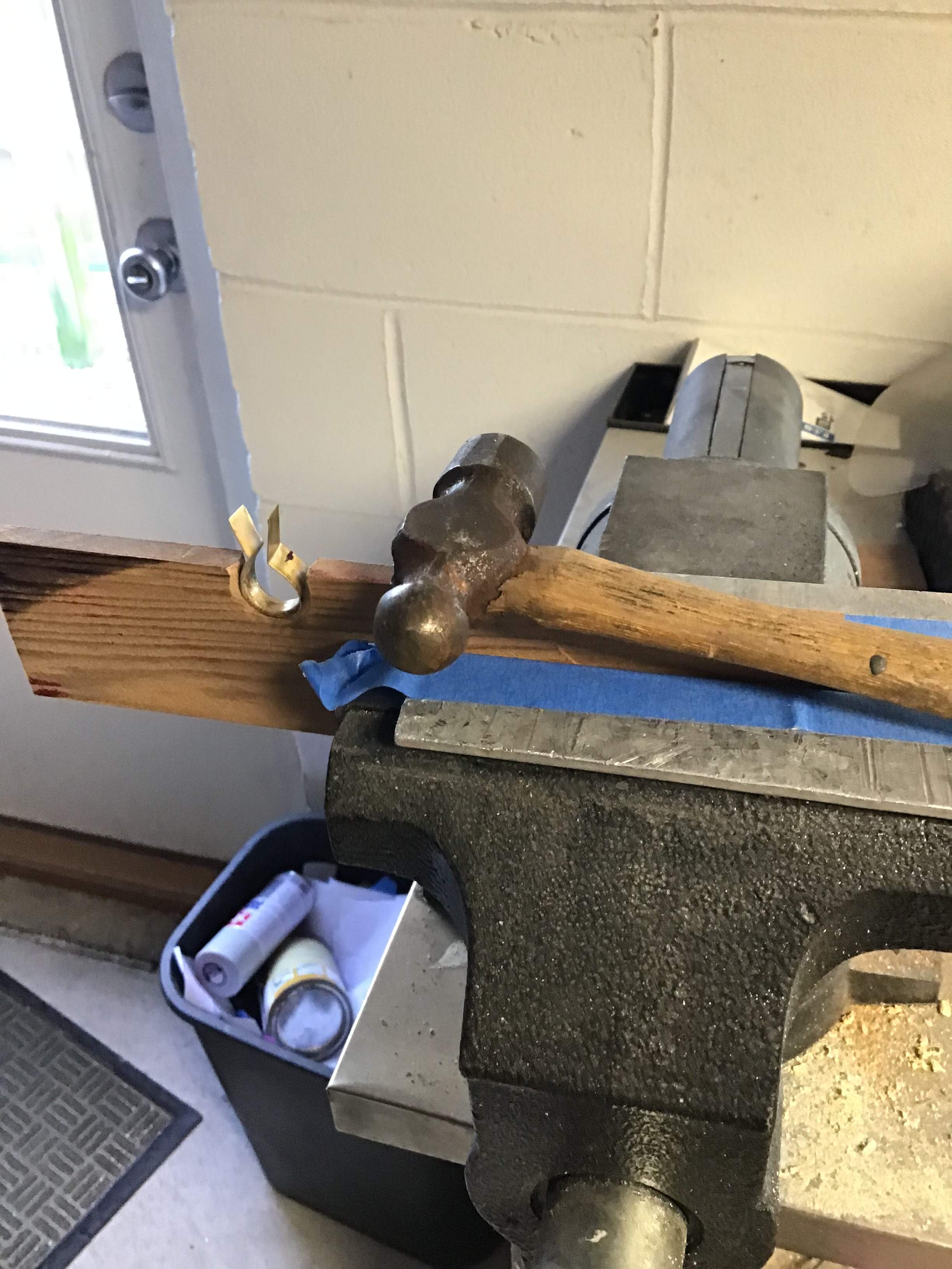
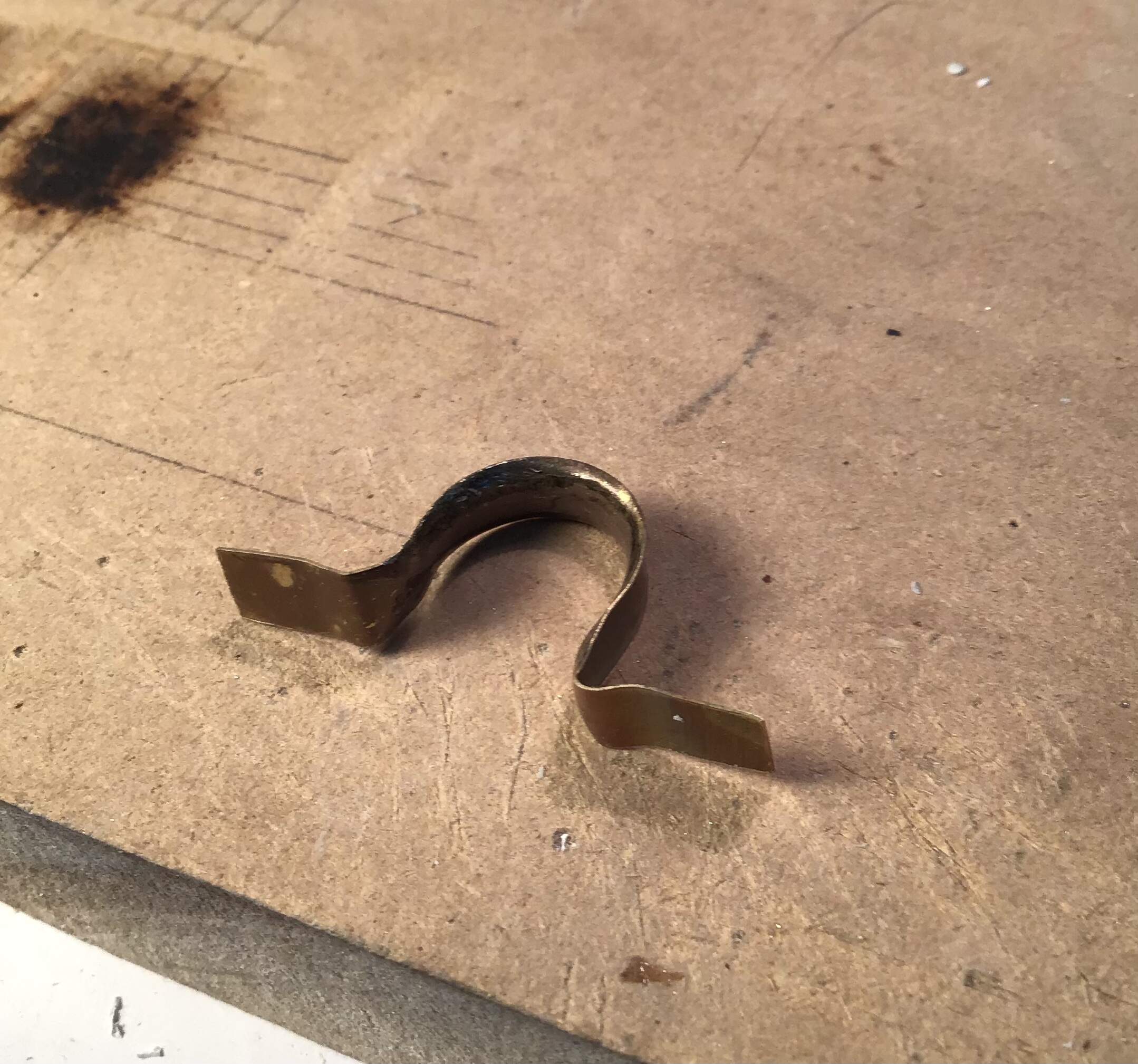
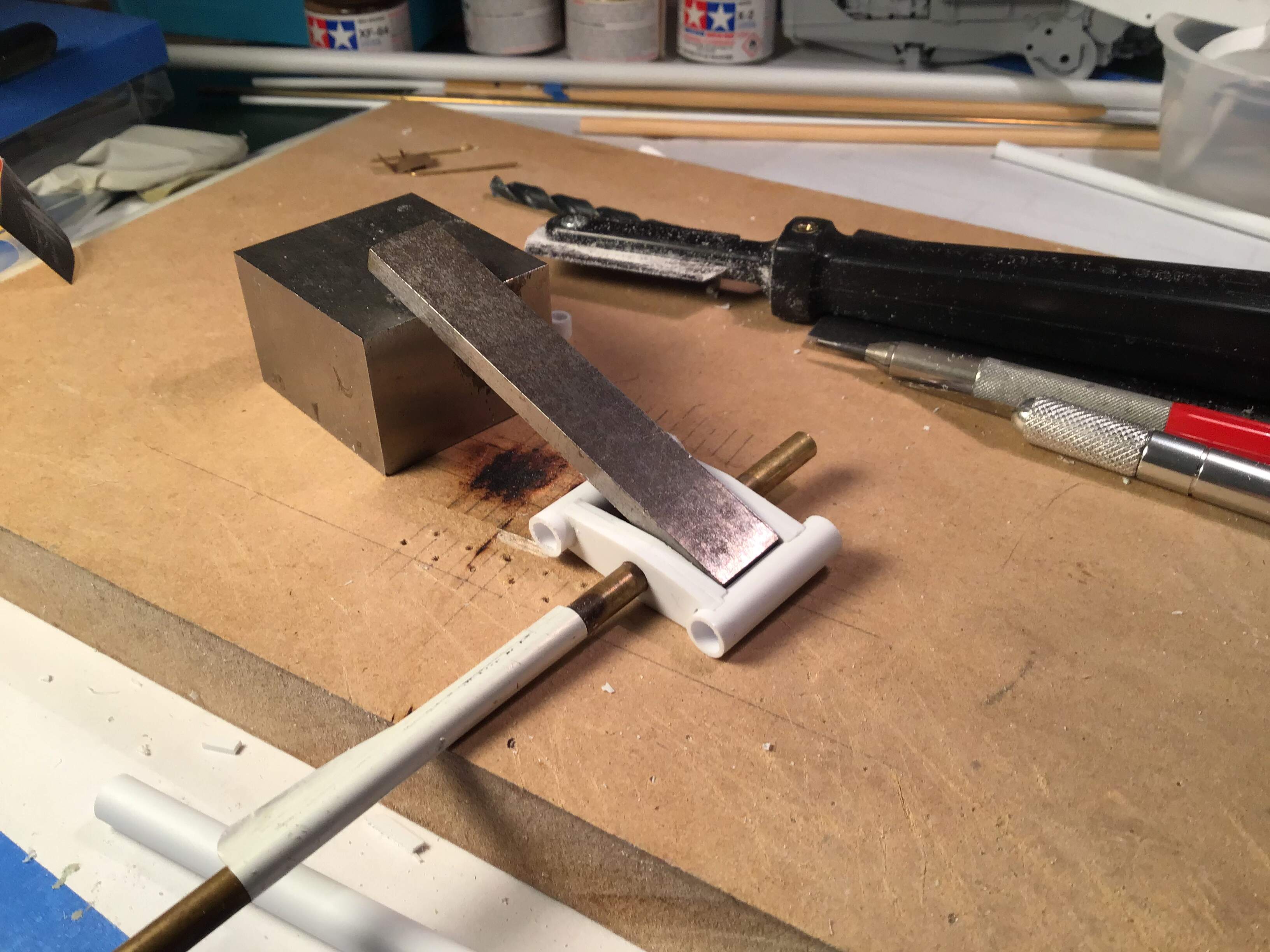
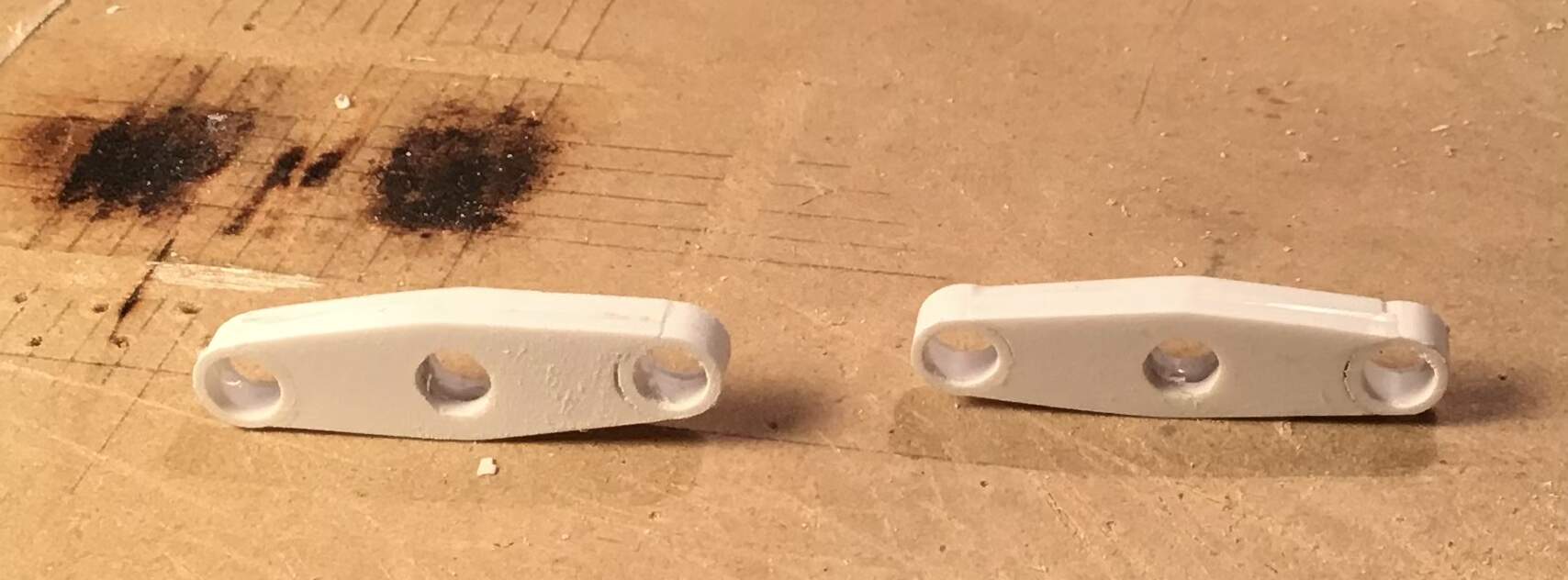
Trimmed to size and fitted to boom -
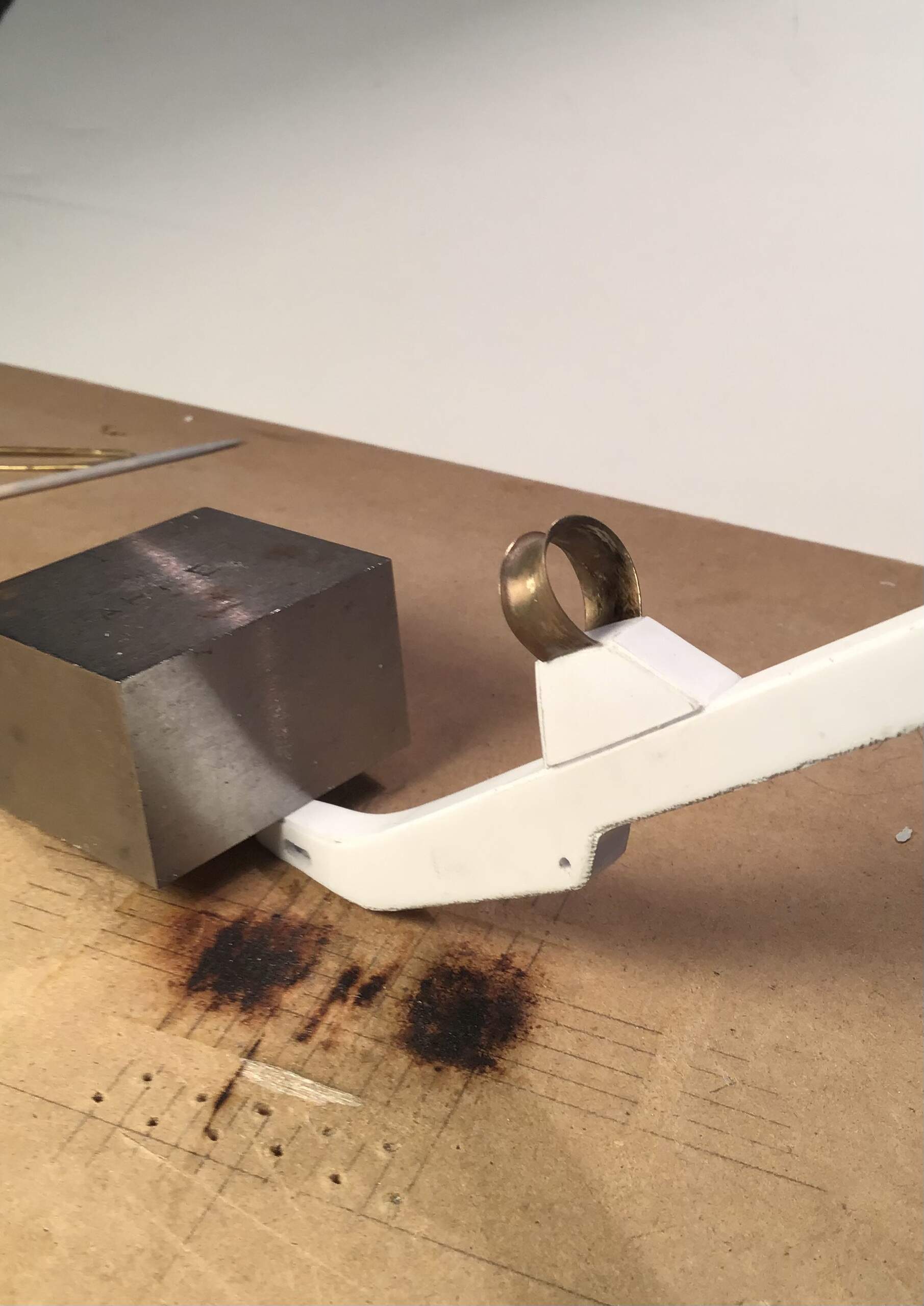

After fastening guides with epoxy I will permanently attach the roller/ fairlead assembly to boom and finish remaining weld beads .
Thanks for looking!
RT
13 Likes
Beginning what may prove to be the most difficult part of the build - the undercarriage. ( although the flared cable guides were no walk in the park )
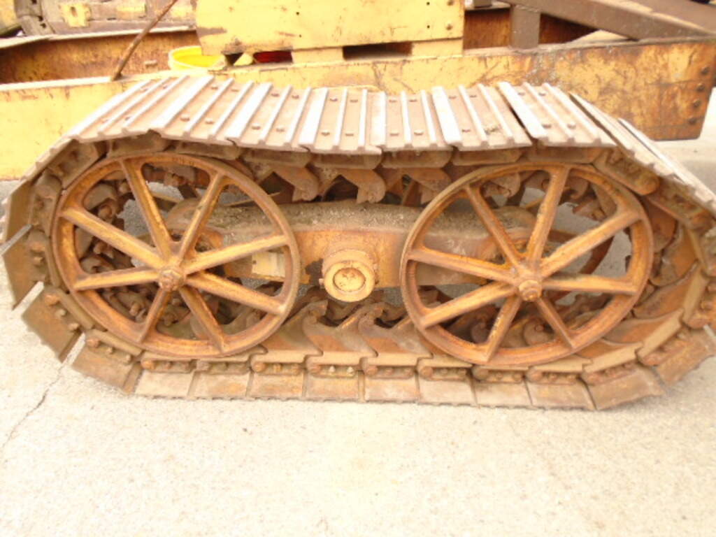
It appears that the entire undercarriage - wheels, track and rocker beams - were manufactured and supplied by the Athey company.
From the manual-
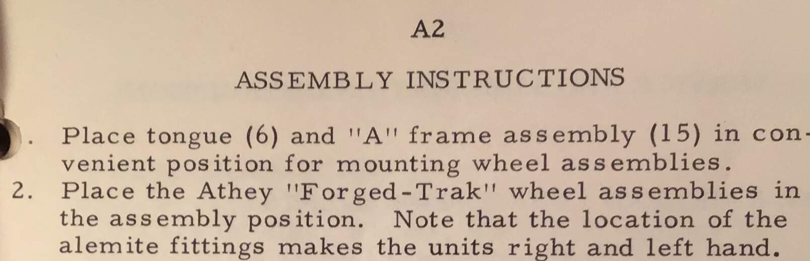
Athey manufactured tracked wagons , dump trailers and other unusual heavy equipment. Of interest is there is no apparent means of adjusting the track tension.
It is my understanding that this was acceptable because the unit was towed - no drive sprocket to skip when things were slack .
Another unusual facet is the enormous size and complexity of the guide teeth . My guess is that this was needed for both the slack in the track and the extreme conditions these arches were expected to operate in. I quizzed my nephew about this who has been involved with tracked heavy equipment for most of his life and he agrees. Perhaps some of the readership here who have first hand experience with armor can weigh in on this subject.
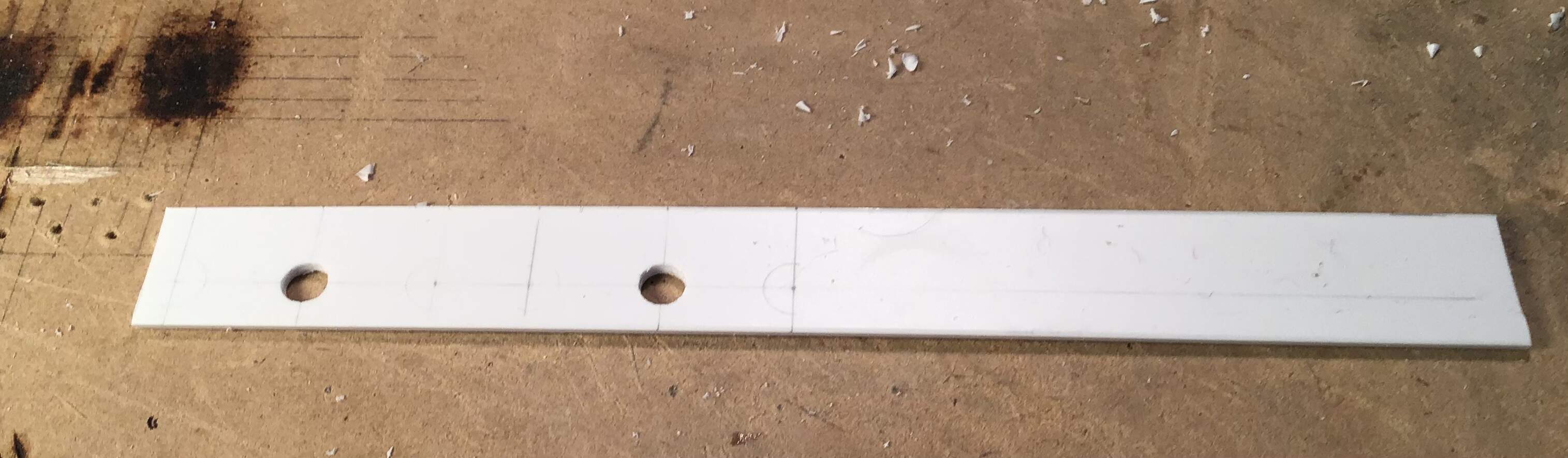
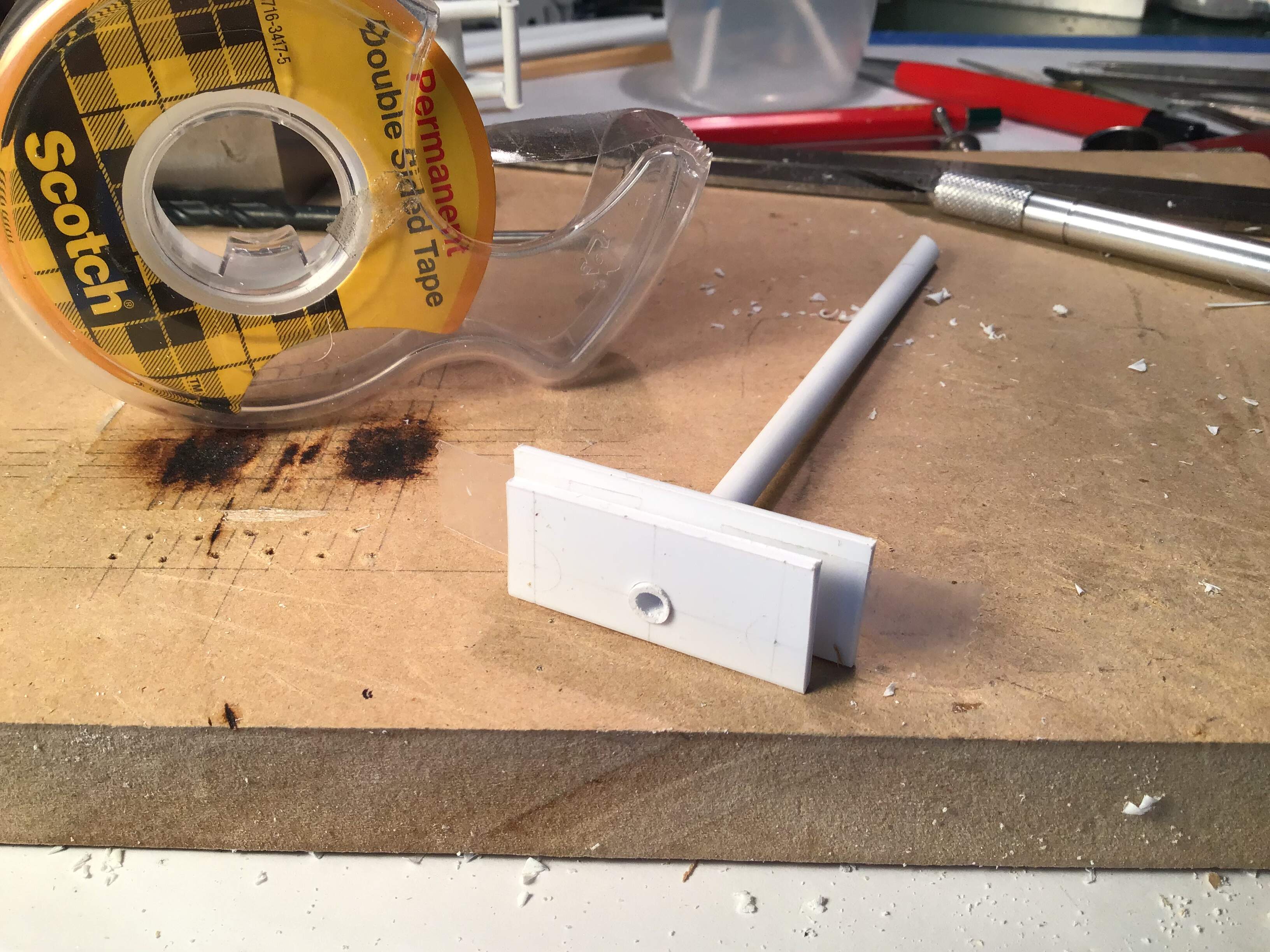
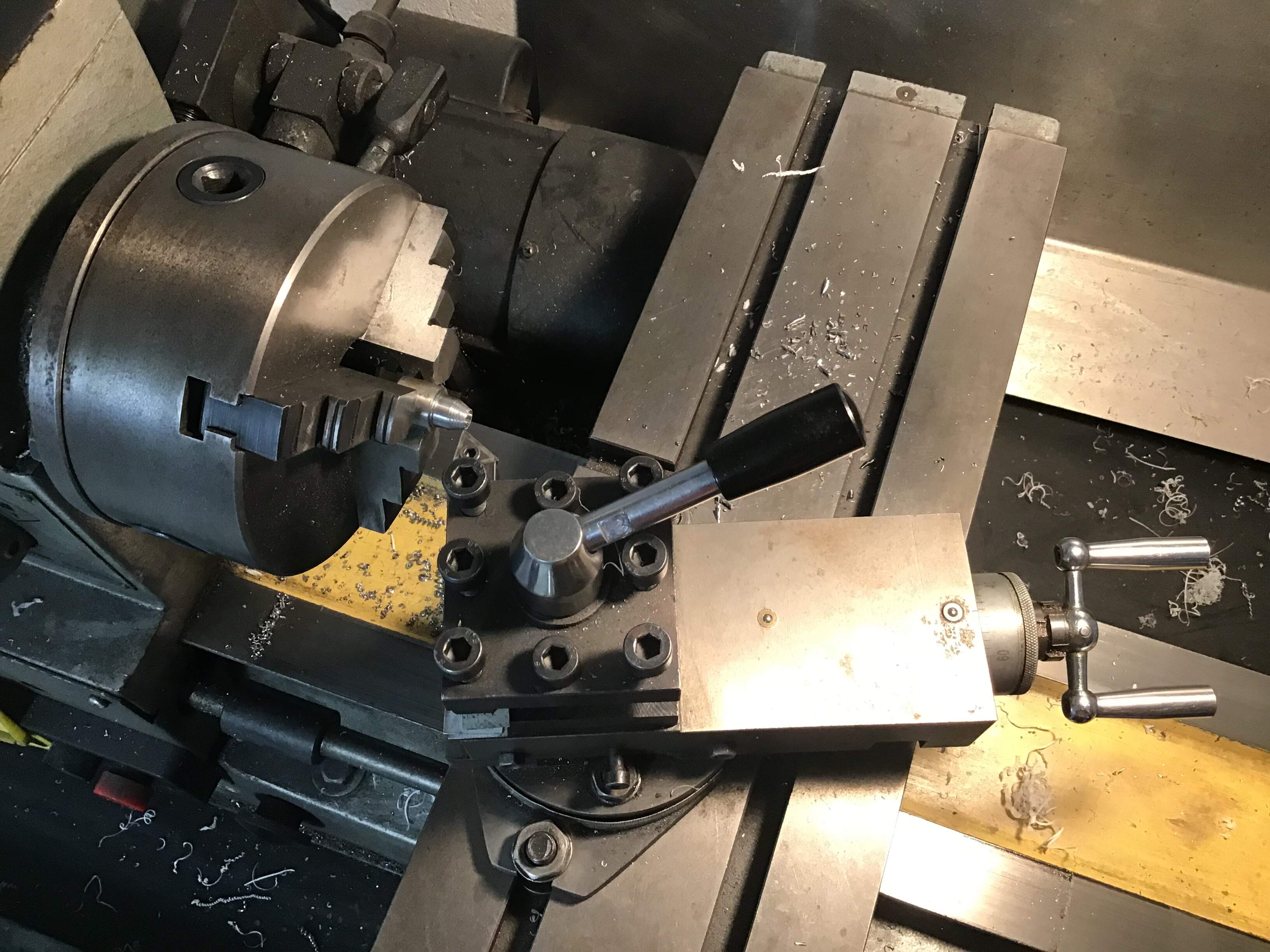
I began by turning some styrene rod to fit the axle tubes on the chassis - these will be bored on the lathe to accept 1/8” diameter brass rod for the axles ( trunnions?) which carry the rocker beams .
Next are the rocker beams them selves . Working from the drawings I laid out four pieces stepping off the distance from center of trunnion to center of wheels . Only two are shown in this photo. Hole bored at trunnion center with bit held in tap wrench to accept styrene tube .
Beam material held together in pairs with double sided tape and indexed by inserting tube through bore .
Ends bored to accept styrene tube with center drill held in tap wrench.
Outline of beams laid out tangent to end holes and sawn with razor saw .

I neglected to take photos but each pair was assembled with spacer in between to build up
width .
Tube assembled to beams in pair with machinist block between to keep all square.
After curing tube sawn through with razor saw and faces dressed off flush .
Some filler will be needed here and there.
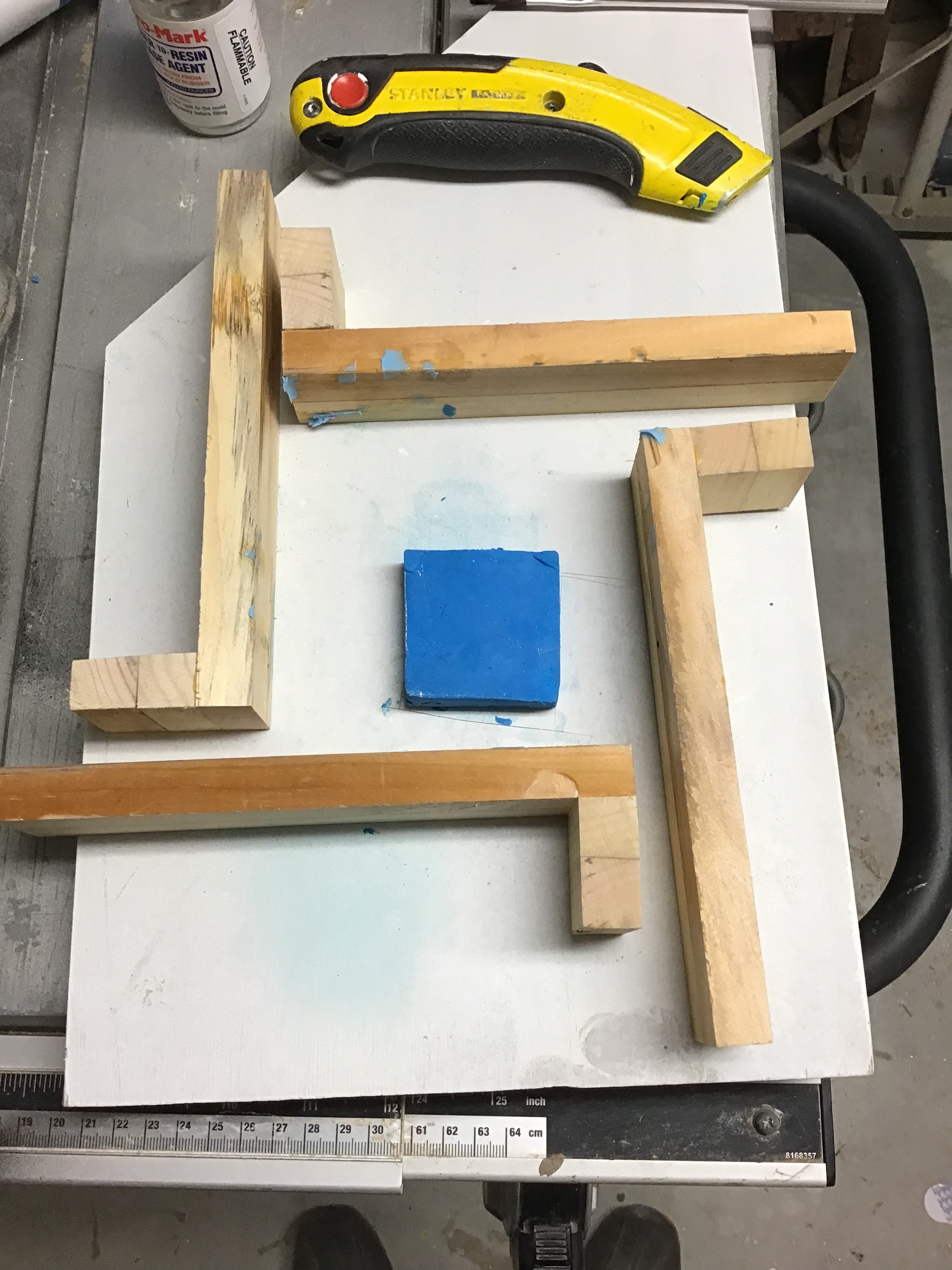
I’ve also been chipping away at the weld beads - slow going as the epoxy putty has a 12 hour cure time .
Thanks for looking and all comments welcome.
Cheers- Richard
14 Likes
Absolutely amazing process. I can barely follow what you are doing, much less do it myself!
2 Likes
Now faced with the task of making eight circular plates for the ends of the rocker beams with a concentric hole in the center .
I elected to make a die to punch them out of plastic.
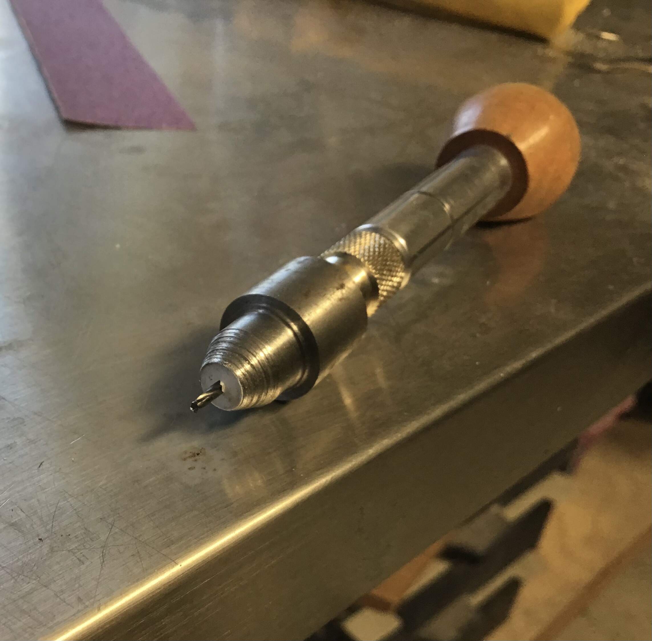
Boring hole in end of apiece of steel rod with a center drill - this bit is the same diameter as the finished disc will be.

Turning taper on outside of die with the compound tool post to produce a sharp cutting edge .
While still in the lathe chuck a hole was drilled through the die in order to be able to drill the concentric hole in the disc .
Punching out discs .

Drilling through die center to produce hole in disc .
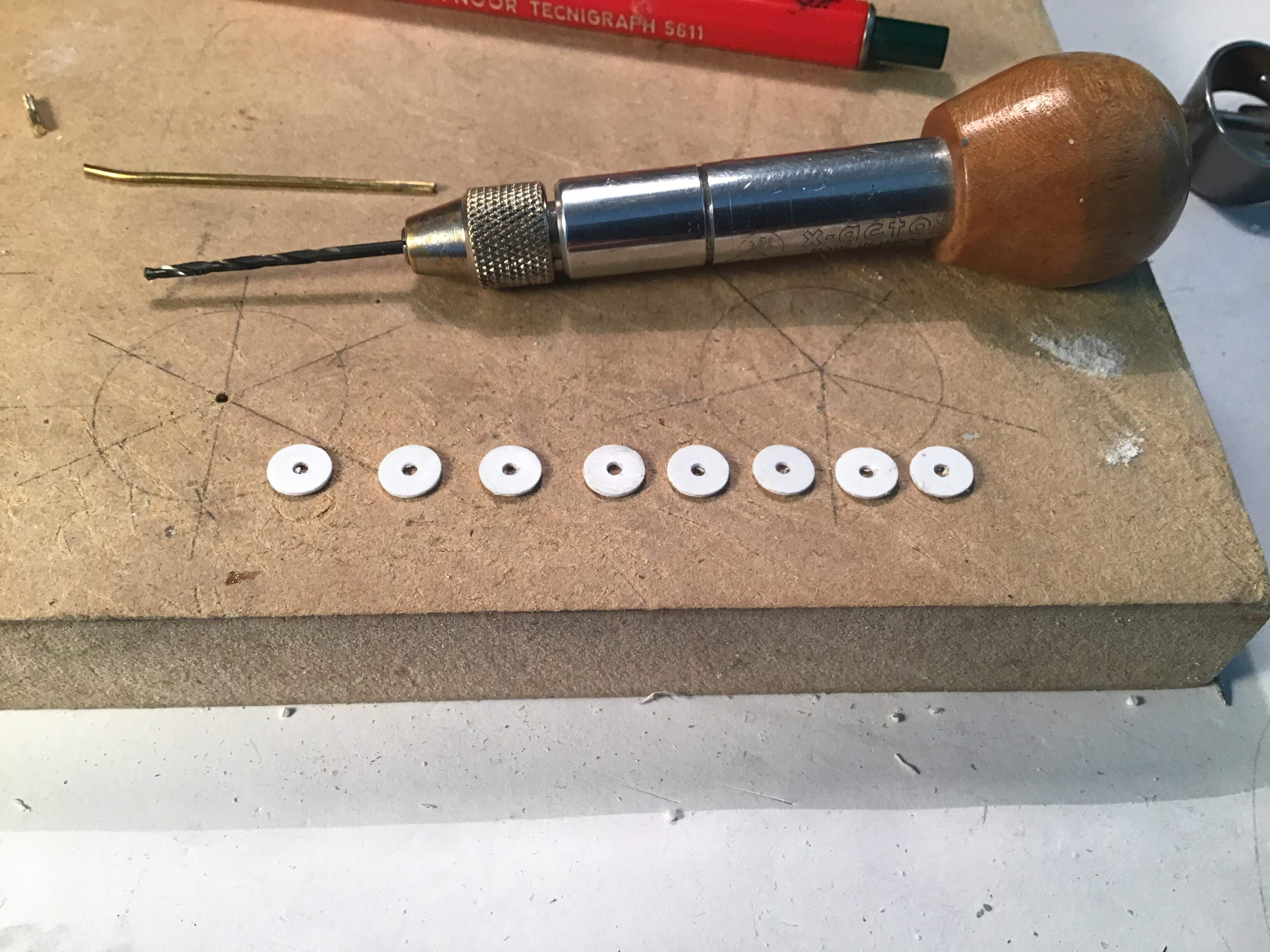
The discs ready for laying out bolt circle - bolt heads will be done with Evergreen styrene hex rod .
More tomorrow.
10 Likes
Clever machining there ![]()
2 Likes
Good thinking ![]()
2 Likes
Thanks for posting many of your work steps, your process is very interesting, and level of craftsmanship - wow!
Cheers
Nick
2 Likes
@KoSprueone
@Uncle-Heavy
@Stickframe
Thanks gents for the interest and compliments- this a fun project to be certain.
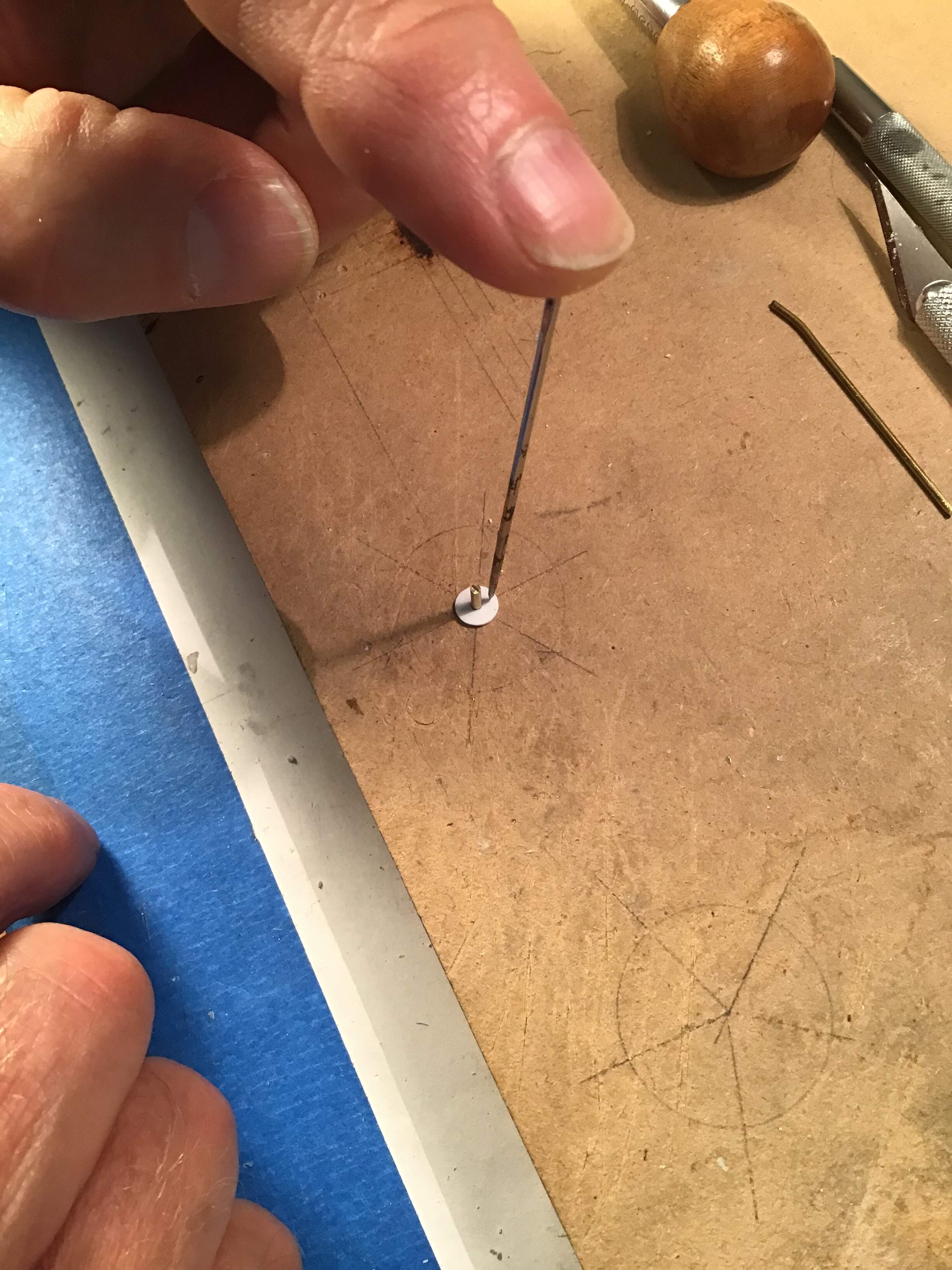
Marking out the discs for the bolt circle -
Marked discs installed on rocker beams -
Hole drilled in .020 “ plastic scrap for a length gauge - .040 “ styrene hex rod inserted and cut flush with ZM nippers to make bolt heads .
These nippers are simply the best .

Bolt heads glued to discs -

Bolt heads sanded down on glass plate -
And the finished discs -
Now to repeat for other side - both beams.
9 Likes
Here is the state of the arch as of this morning -
major components dry fitted together temporarily.
There are a couple of weld beads yet to do on the horseshoe shaped chassis and the lengths / details of the trunnions need to be worked out . This will be a function of the wheel spacing and track width.
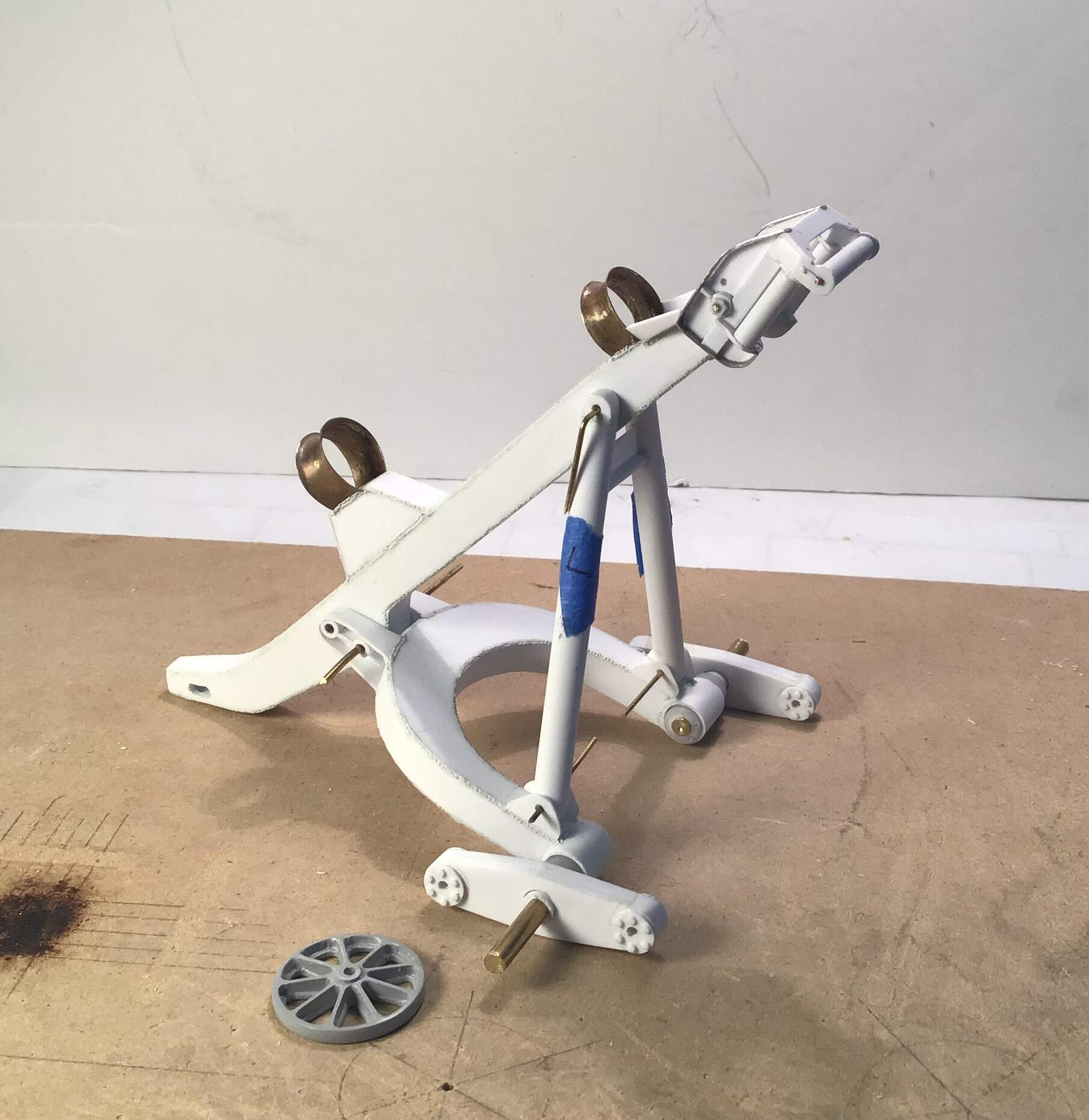
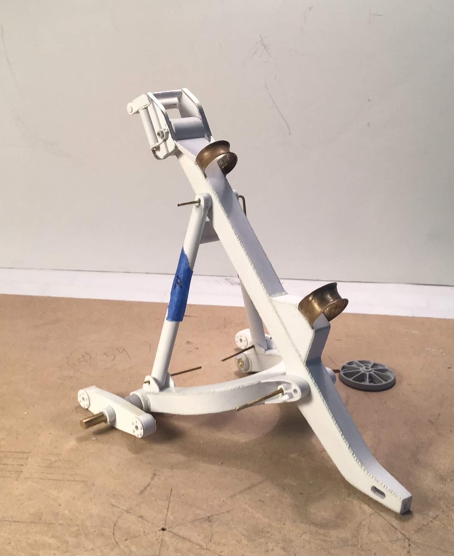
getting anxious to see it in primer .
12 Likes
It already looks great!
Waaay beyond my skill level…
3 Likes
Hi Richard… That’s some great scratch building.
Cheers,
Ralph
2 Likes
Perfection.
1 Like
Outstanding scratch building. At first I thought this was a piece of exercise equipment in your house.
4 Likes
LOL - the exercise equipment is covered in dust & cobwebs…
4 Likes
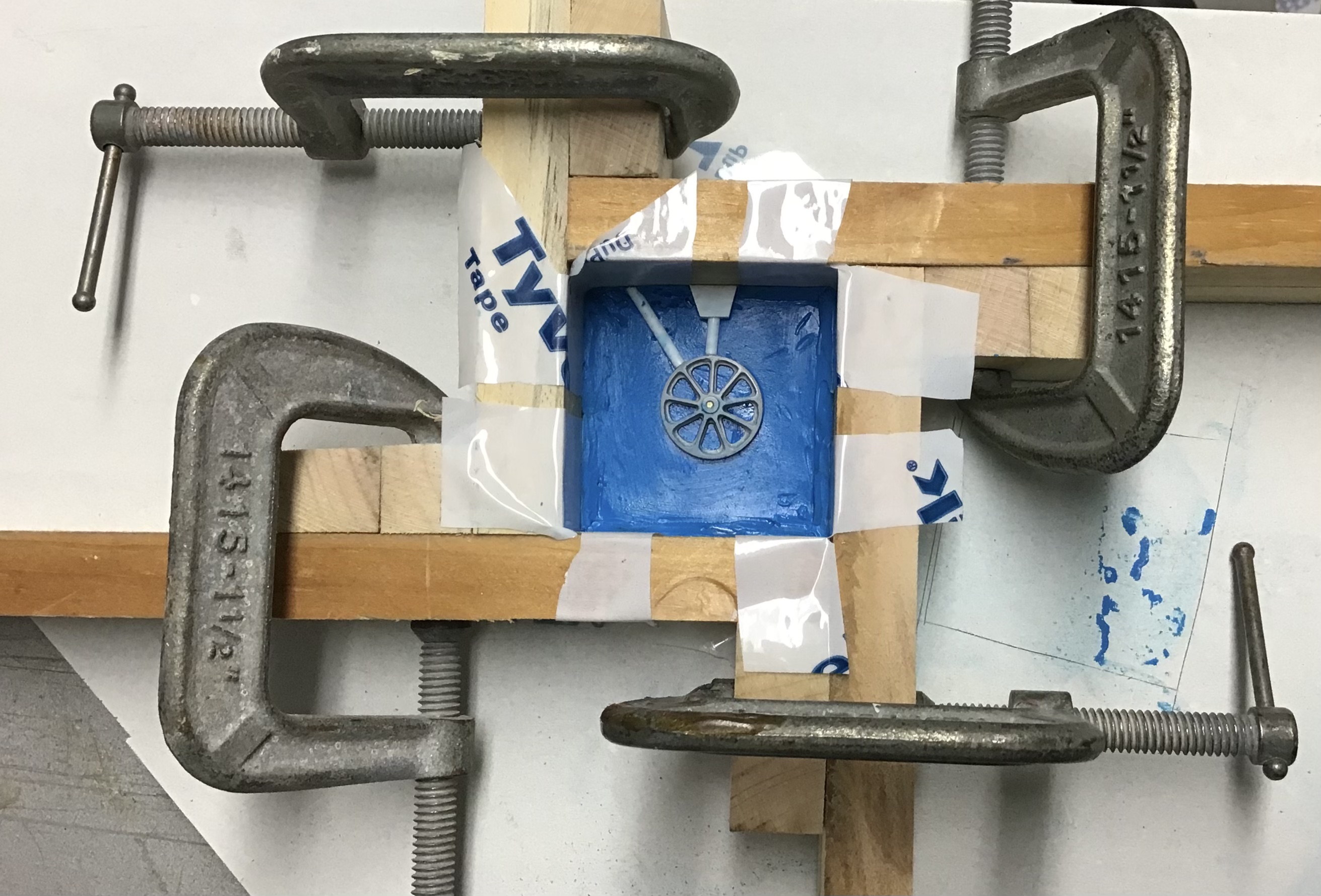
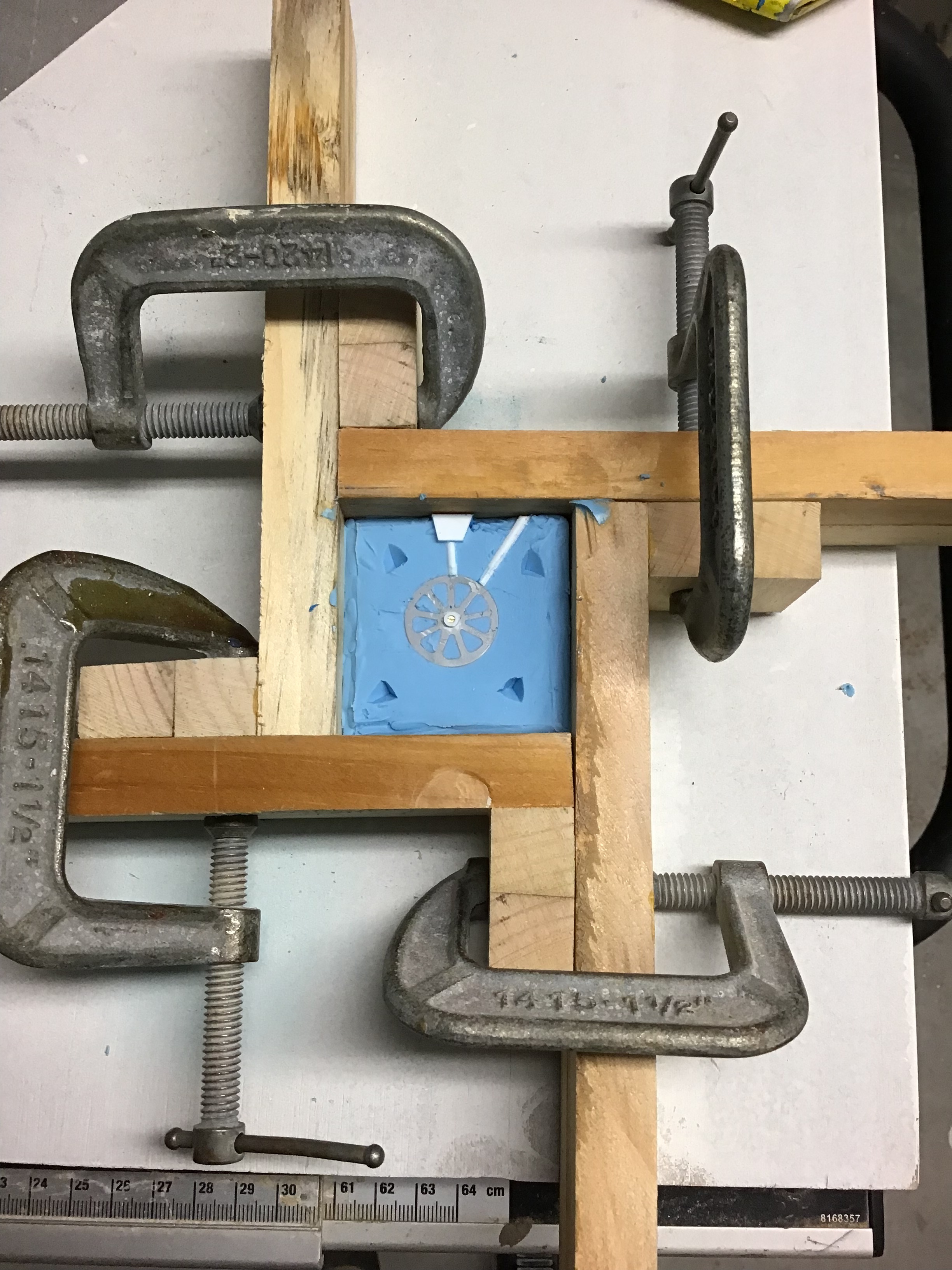
Made a start on casting the wheels by creating a silicone mold . This is a first for me .
Start with rolling out a square of silicone compatible modeling clay and trimming the edges …

Mold box arranged around clay …
Mold box clamped and master pattern set in
place … note pour sprue and vent .
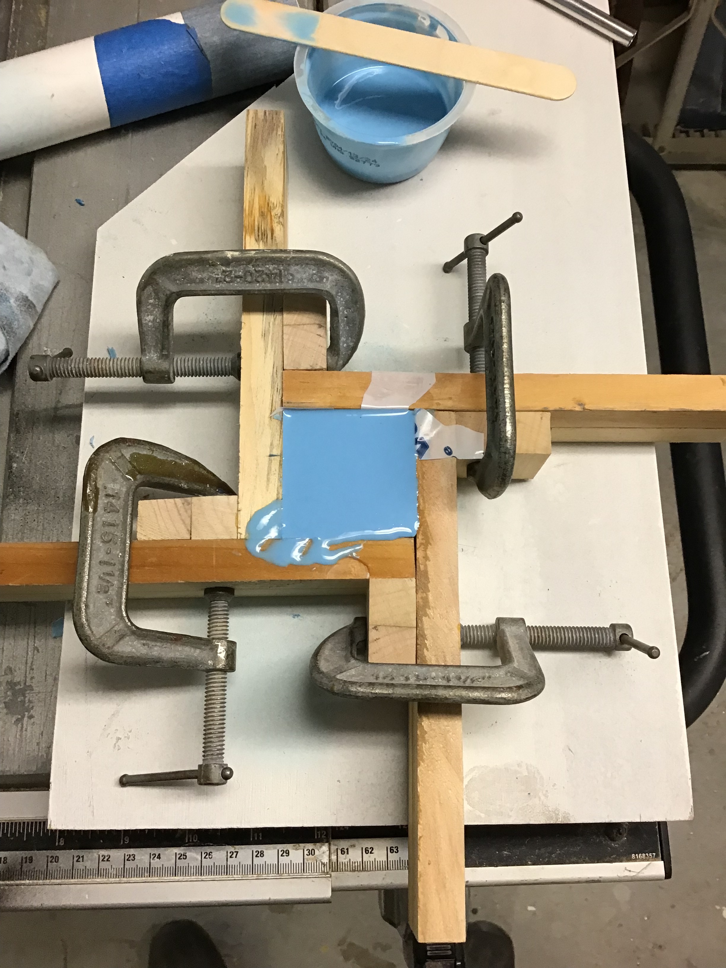
Release agent painted on master and mold and silicone poured …
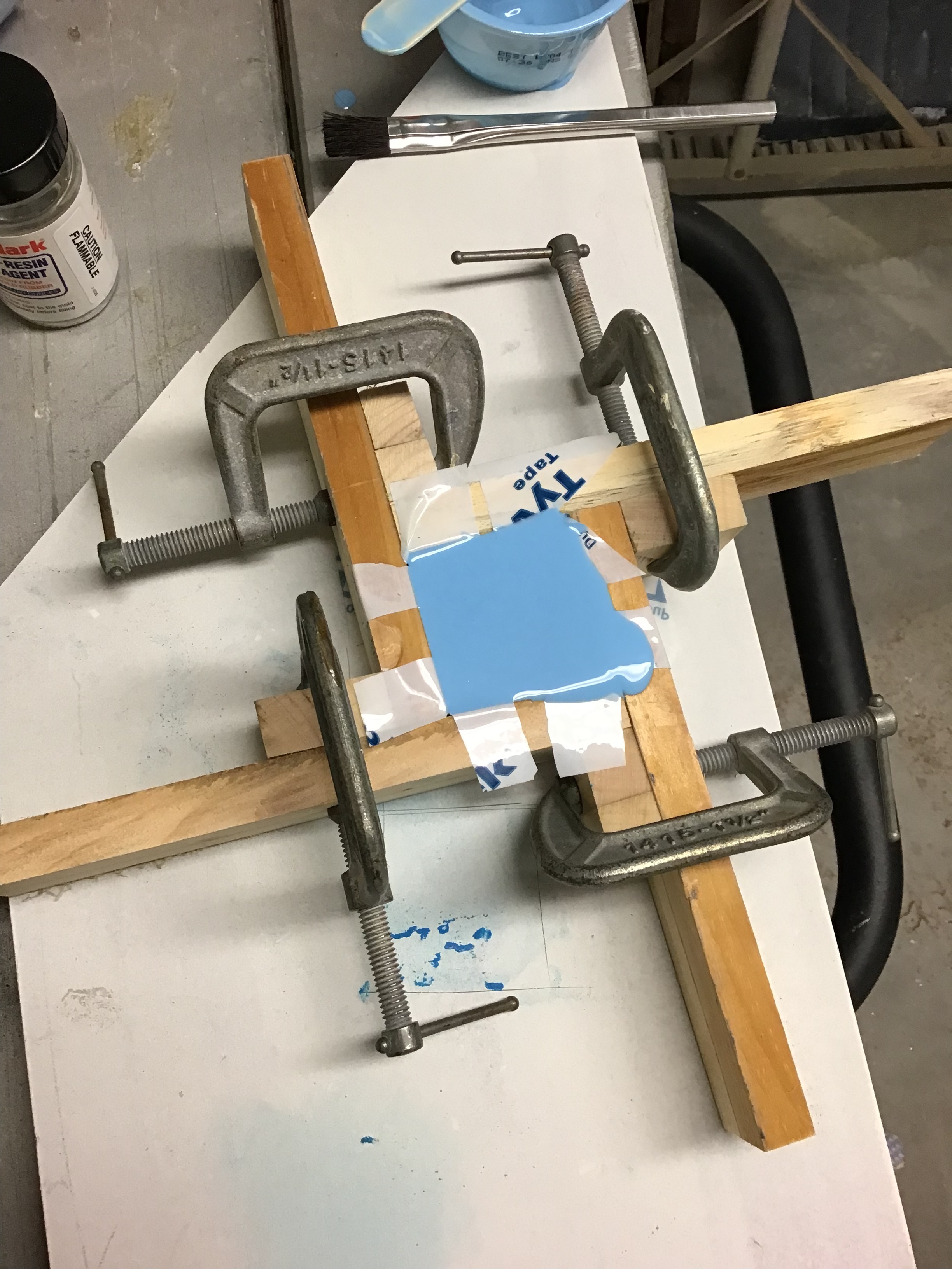
First half done and registration keys cut into mold with knife…
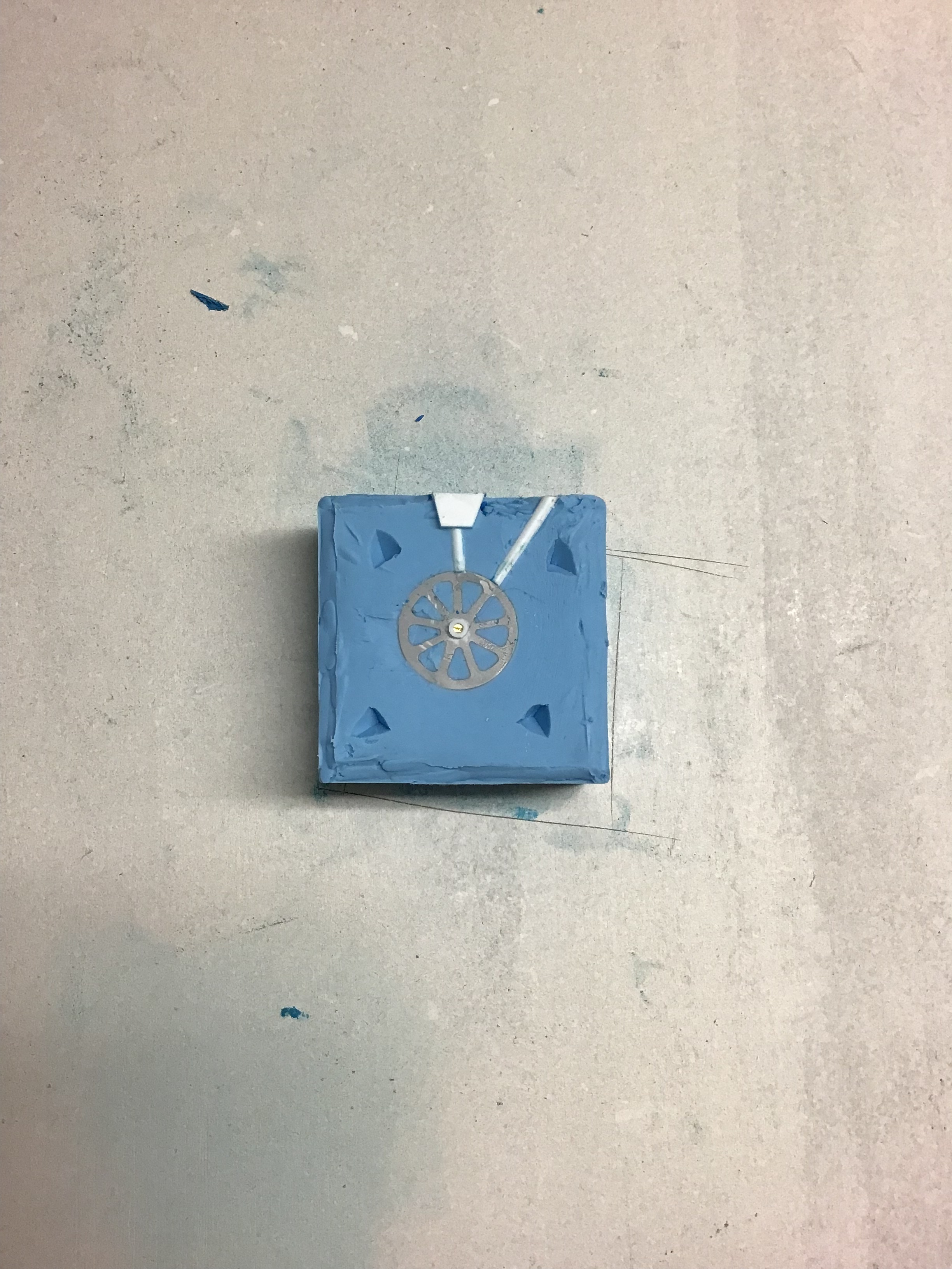
Mold reset in mold box and clamped . Rubber to rubber release agent painted on and ready for pouring second half of mold …
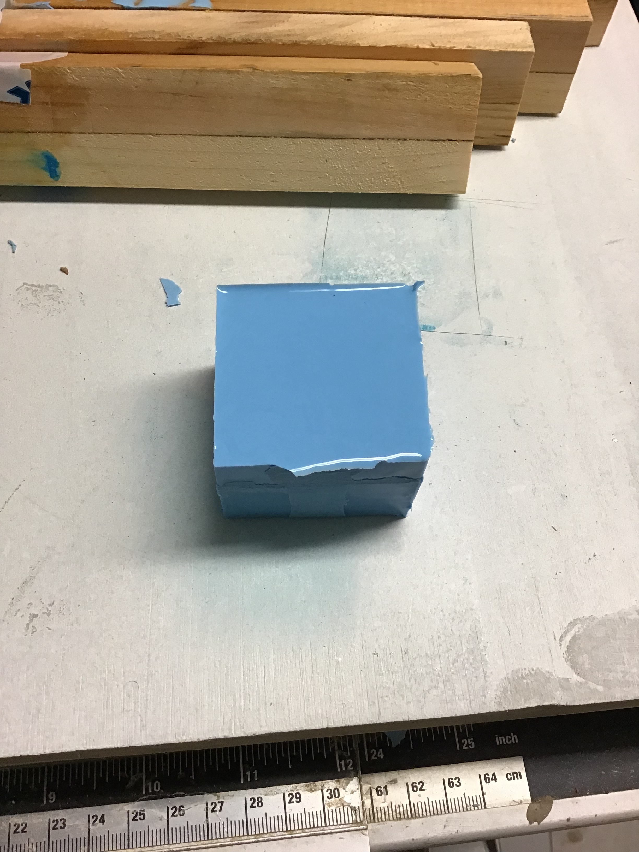
Second pour …
Mold released from box …
And halves split and pattern removed…
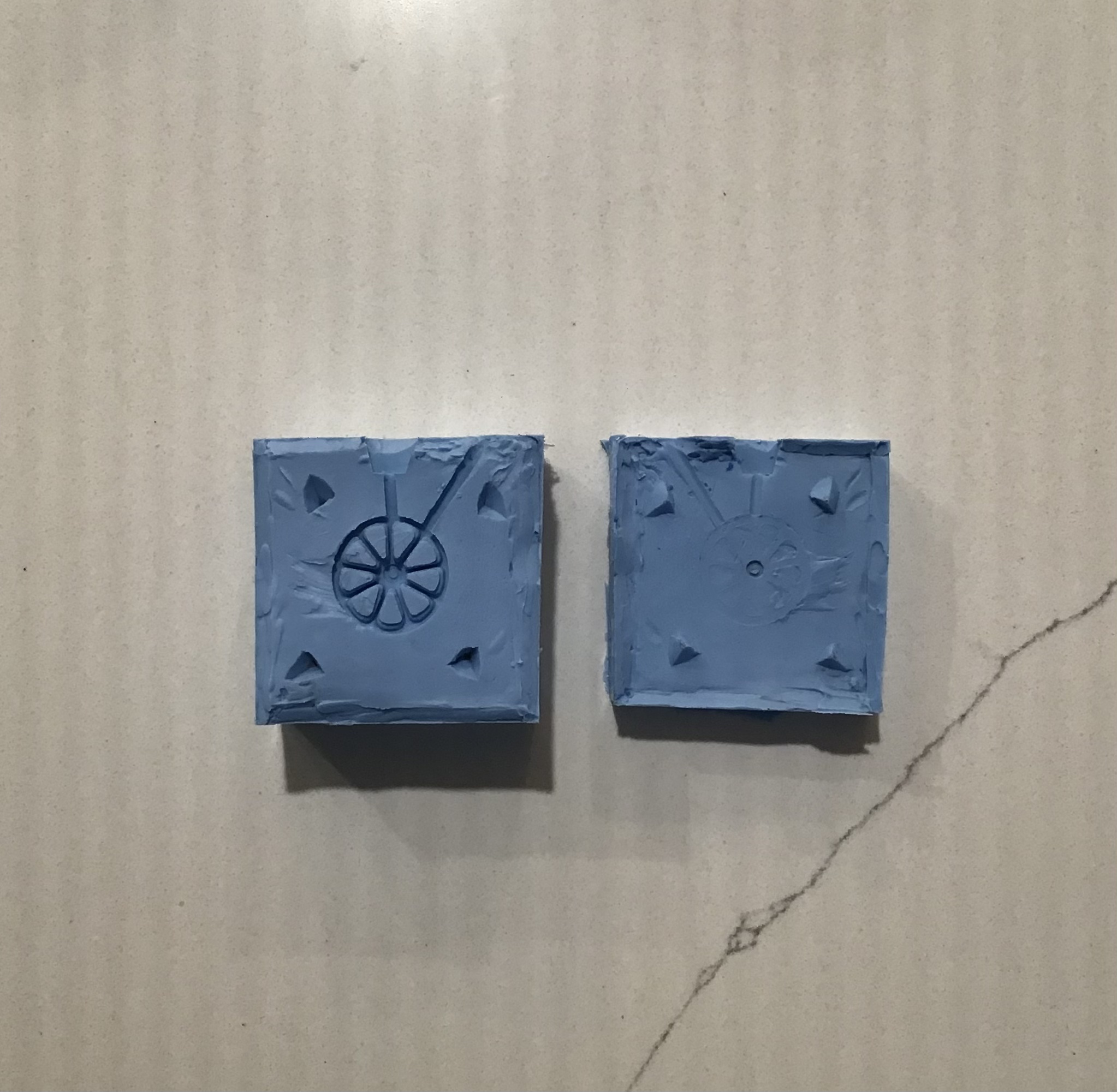
The pour reservoir and vent…
Tomorrow should see the results of the first
casting - fingers crossed !
Thanks for looking- RT
9 Likes
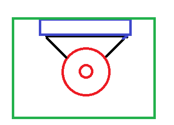
Richard. Your pour tube may be a little thin and there is no vent on the left. There is a lot of places air could still be trapped. Given there is next to no detail on one half though, I suggest you pour the resin directly into the half with the detail - say pour into the hub and let it flow down the arms and to the rim, to push the air out as it goes. Once done, place the other mould half over that, then secure them together (a sandwich of two thick styrene squares on each side, held by rubber bands. The squares will stop the bands from pulling the edges in and bowing the mould). Tip upright and tap gently to get any air bubble to rise to the top.
When casting wheels, the best way is to make a triangle of .20 thou styrene and cut the tip off with an arc that the wheel fits into. Then glue the base of the triangle to a long length of Styrene square section. That becomes the master. That way, using the sandwich to hold it together, you can squeeze the sides to bellow the mould, pour in one end and let it flow down then up, and it will push out the air. The wide opening of the triangle lets more air out. When the mould is full, stop squeezing and let the sides come together and push surplus resin into the rectangle reservoir:
2 Likes