Miniart SdKfz 234/4 build log

Hey all,

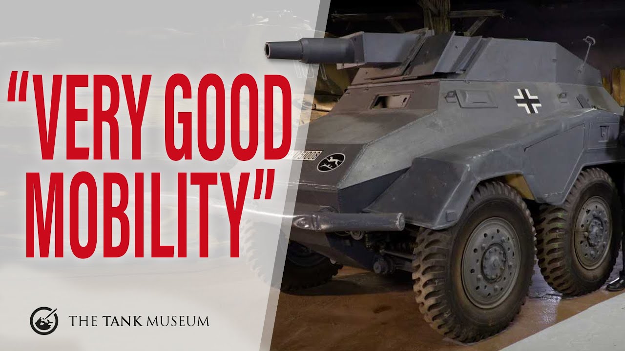
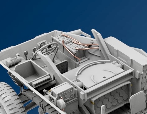
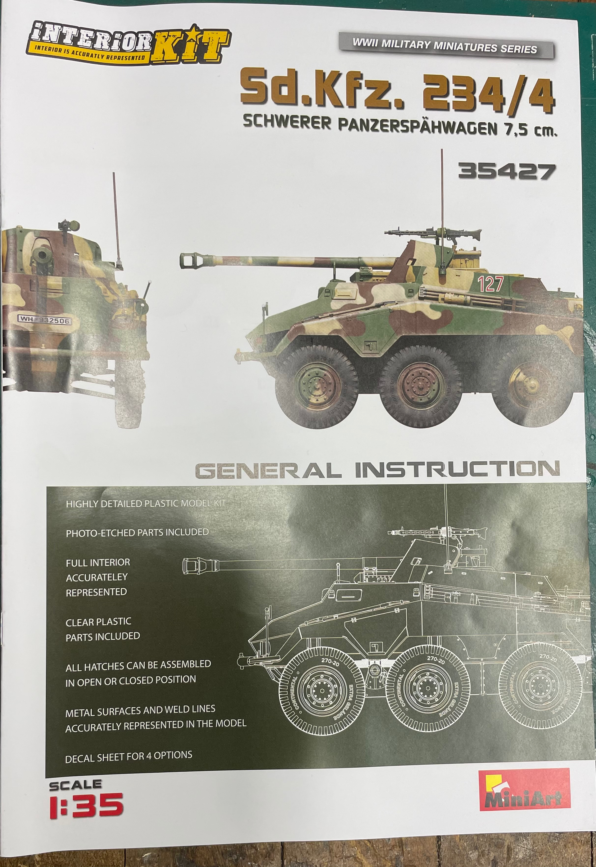
This is the start of my build log for the Miniart SdKfz 234/4 Schwerer Panzerspahwagen 7.5 CM. Interior kit.

As i am a builder who comes and goes yearly, and having built one Miniart kit before, i wanted to try a new kit. When i research for a new kit, typically the only reviews you will find are what’s in the box types reviews, which, to me, are pretty much lame.

I want to know the difficulty on a build, not whats included.

I enjoyed the last Miniart build i did, so i chose this at my LHS.

So now i will attempt to do this log.

If you haven’t build a Miniart kit, there are some immediate things that are nice to know.

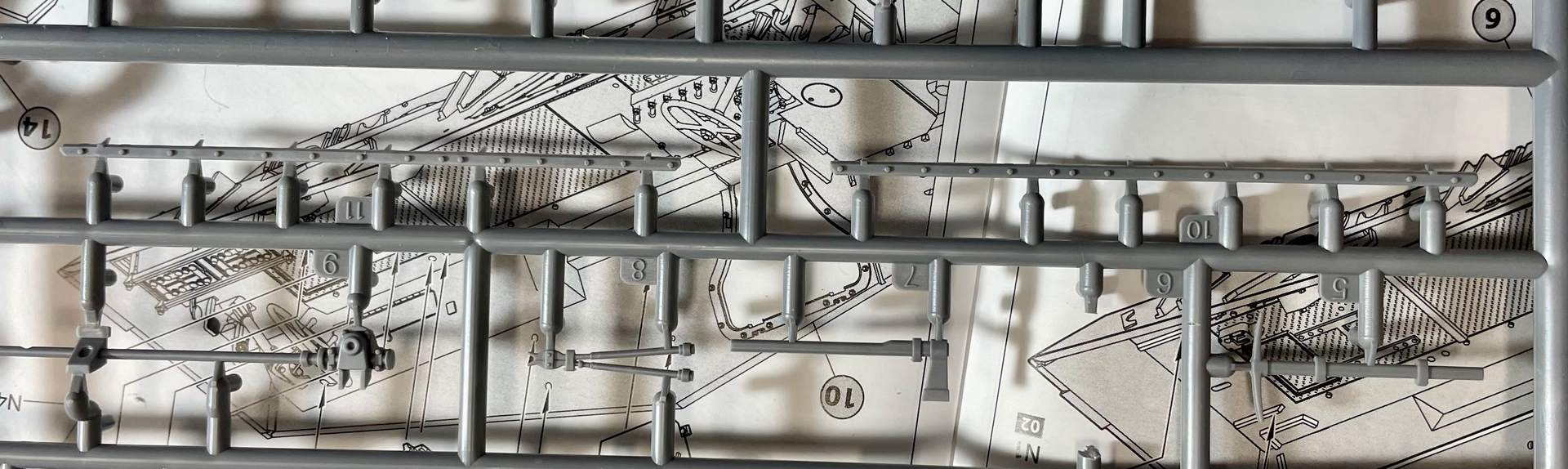
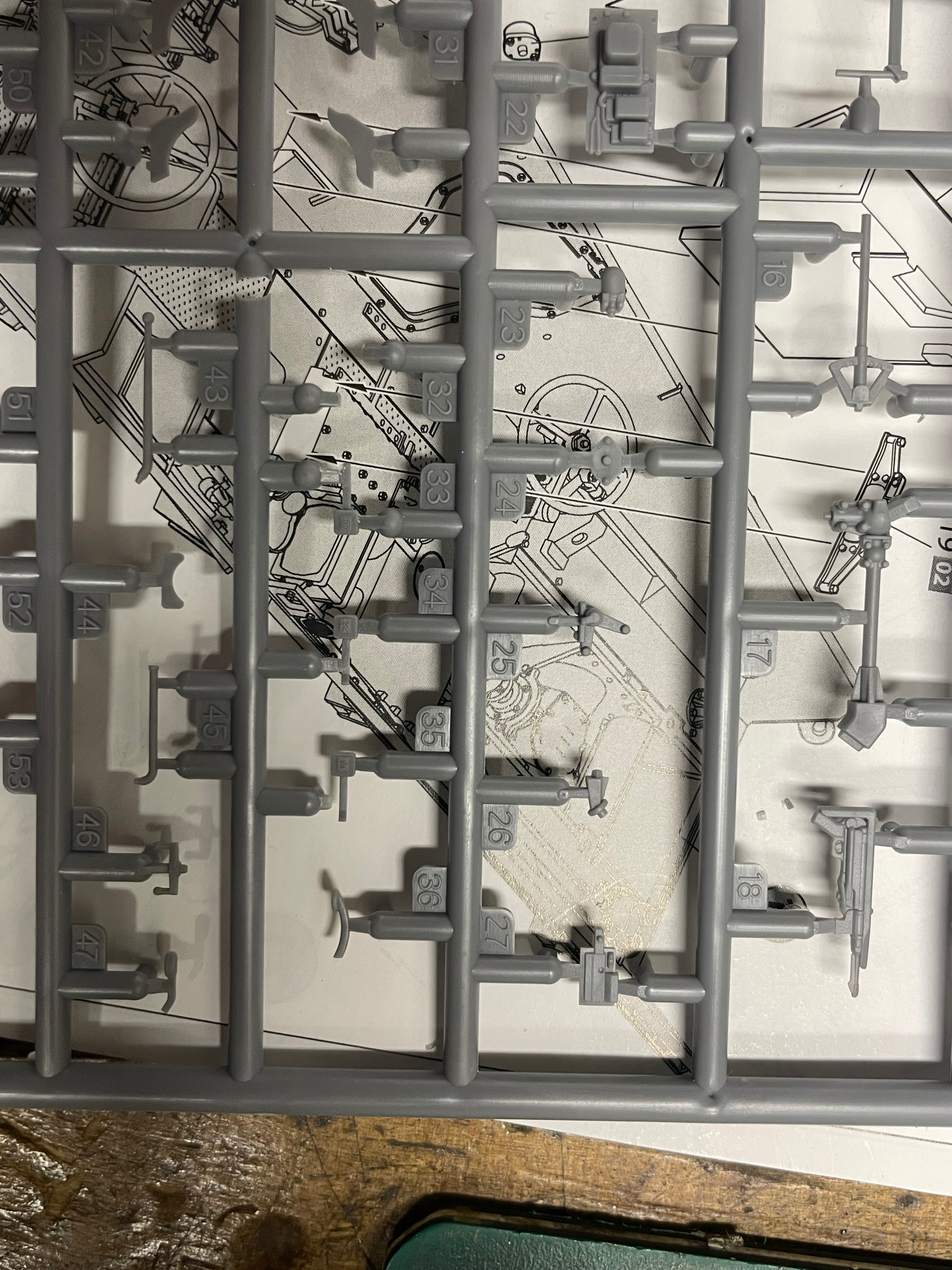
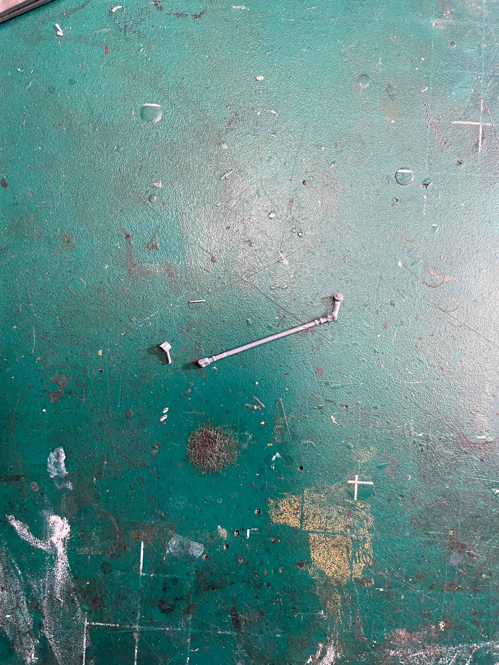
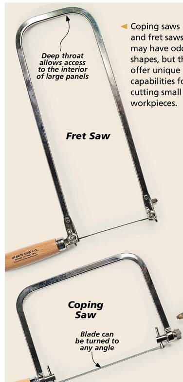
The plastic is soft. It is very easy to maim and break. A razor saw, IMO, is one tool that will make your life easier. There are usually , many small, thin parts that if you try to remove with cutter, it WILL break the part. ( controls rods and stuff)

The plastic bonds well with Tamiya extra thin.

These are my basic warnings, after building the first kit I built from them.

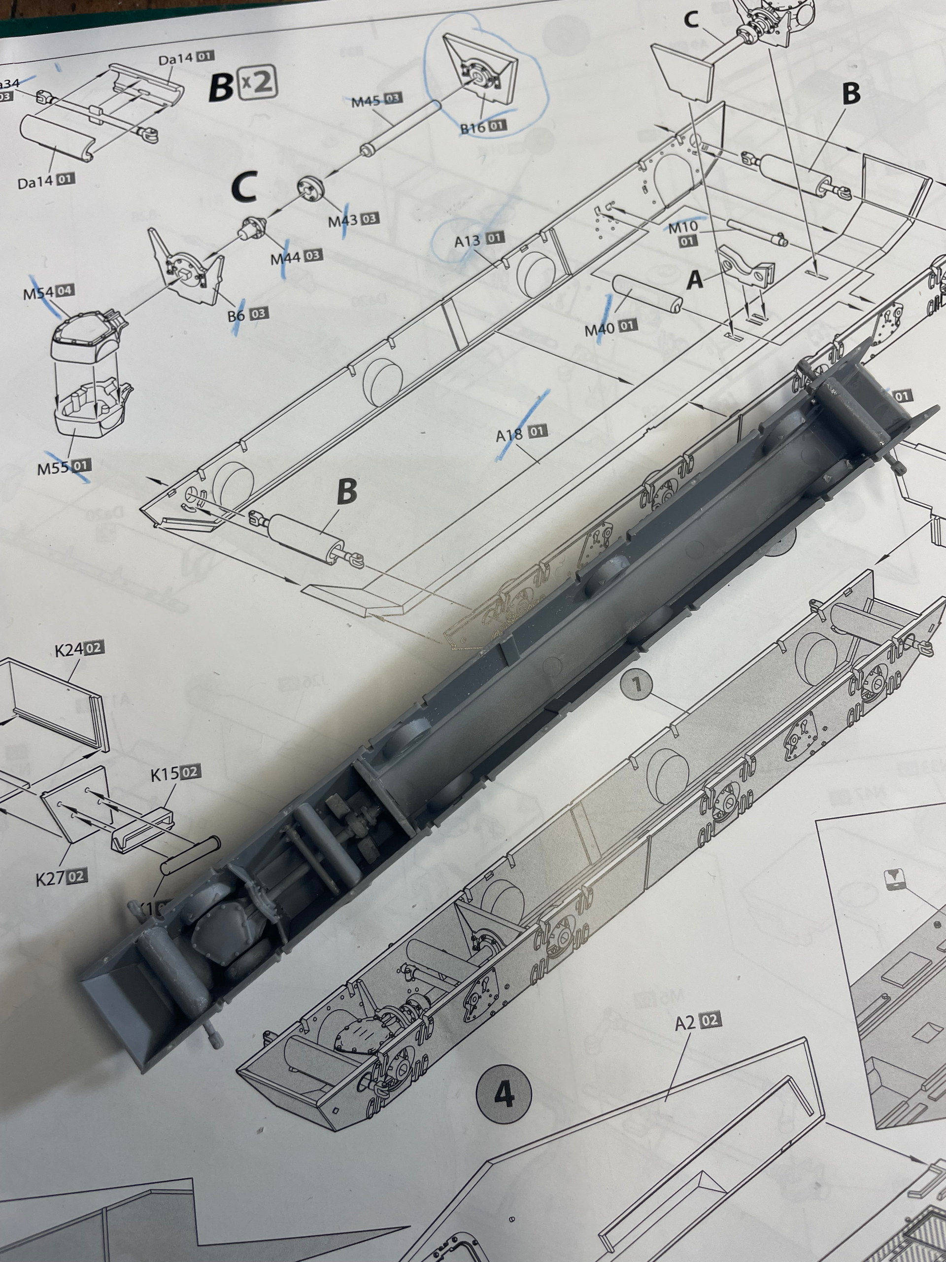
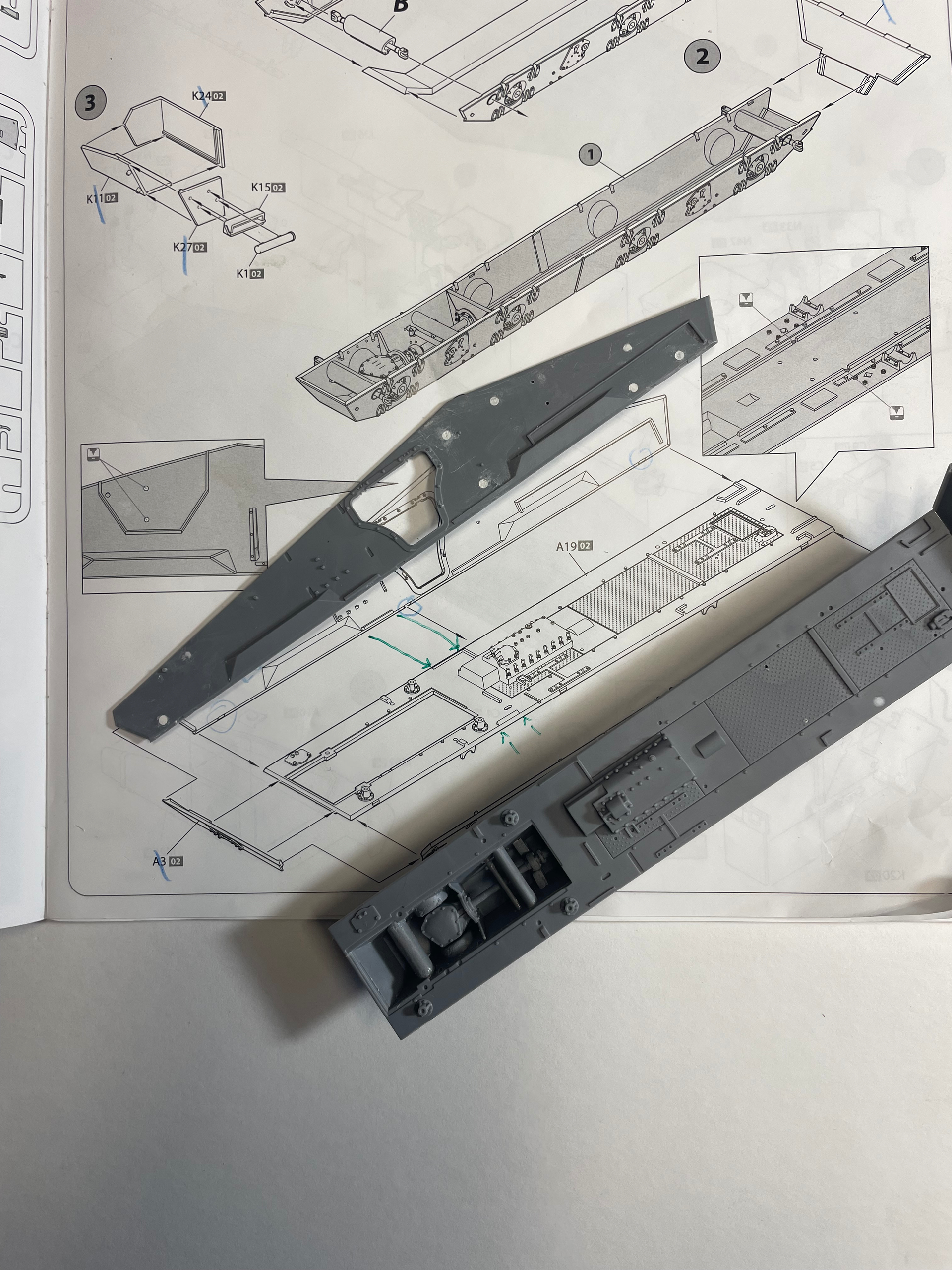
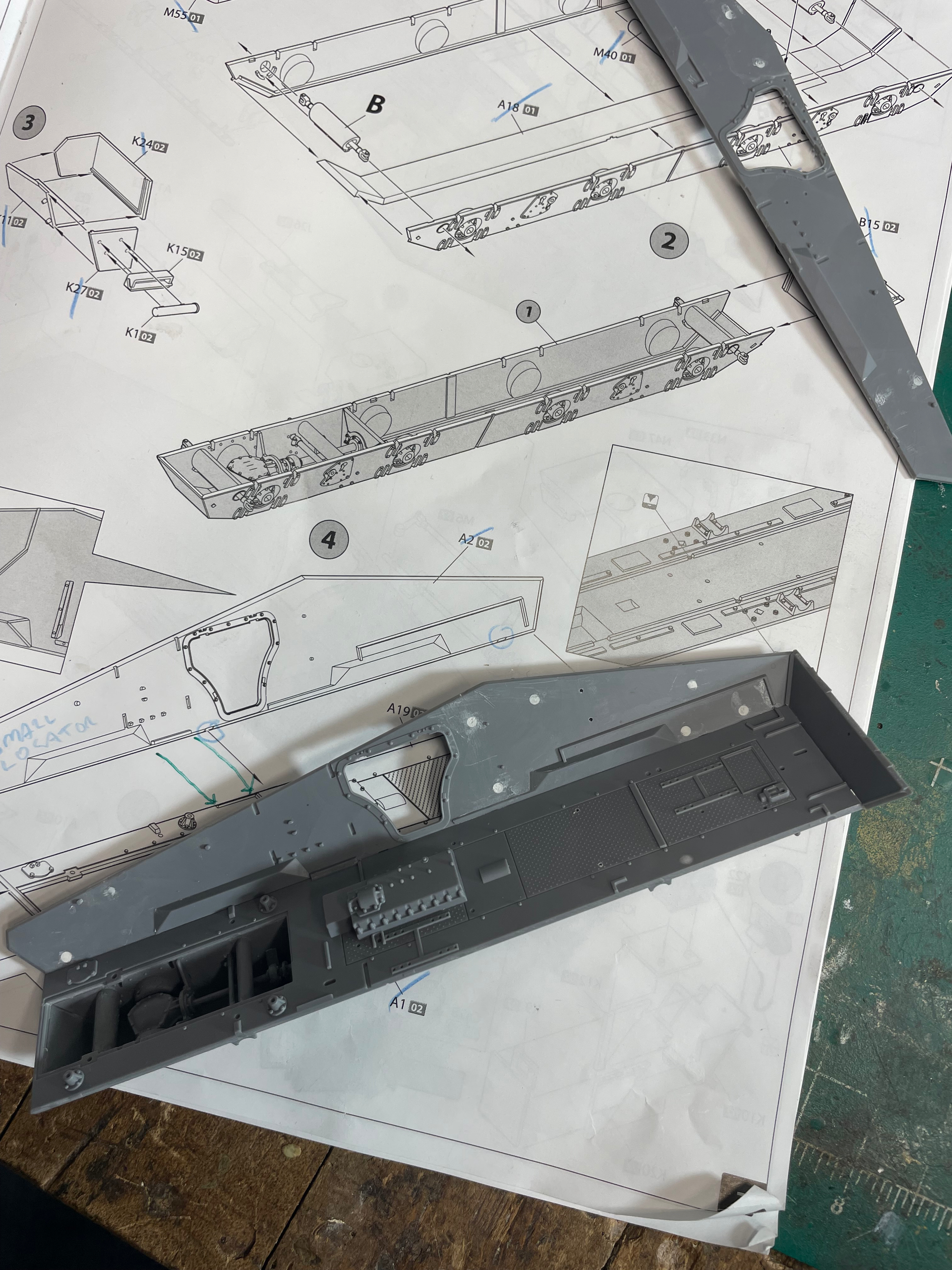
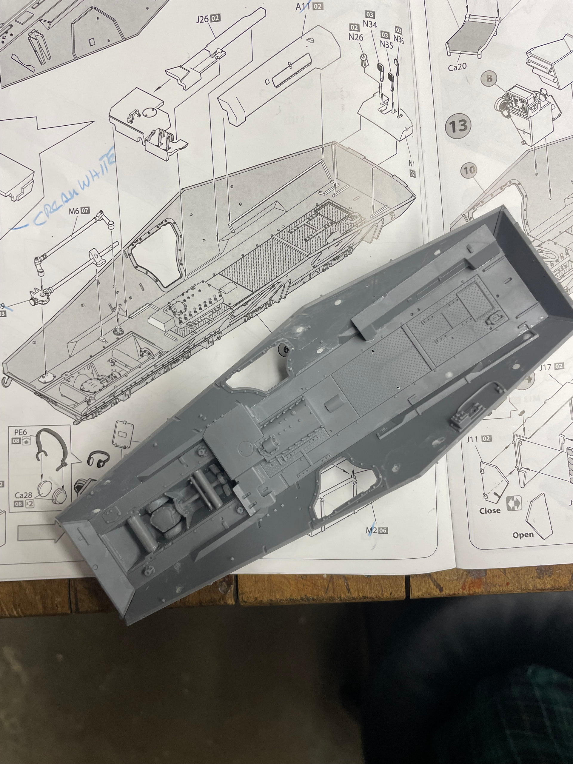
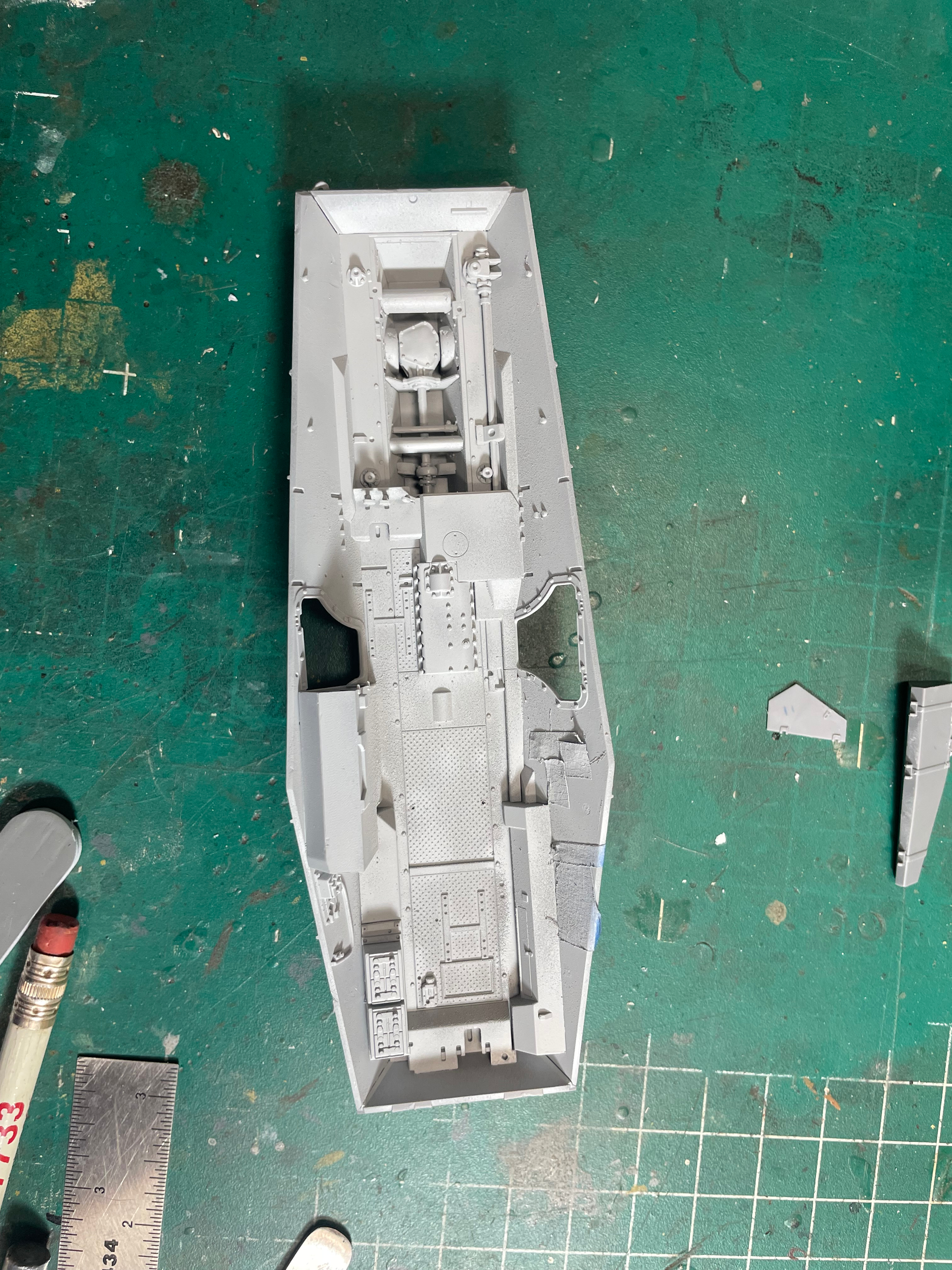
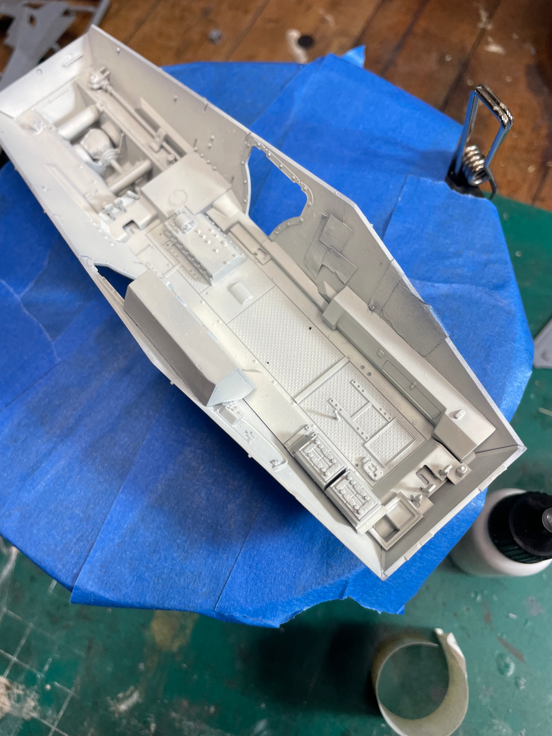
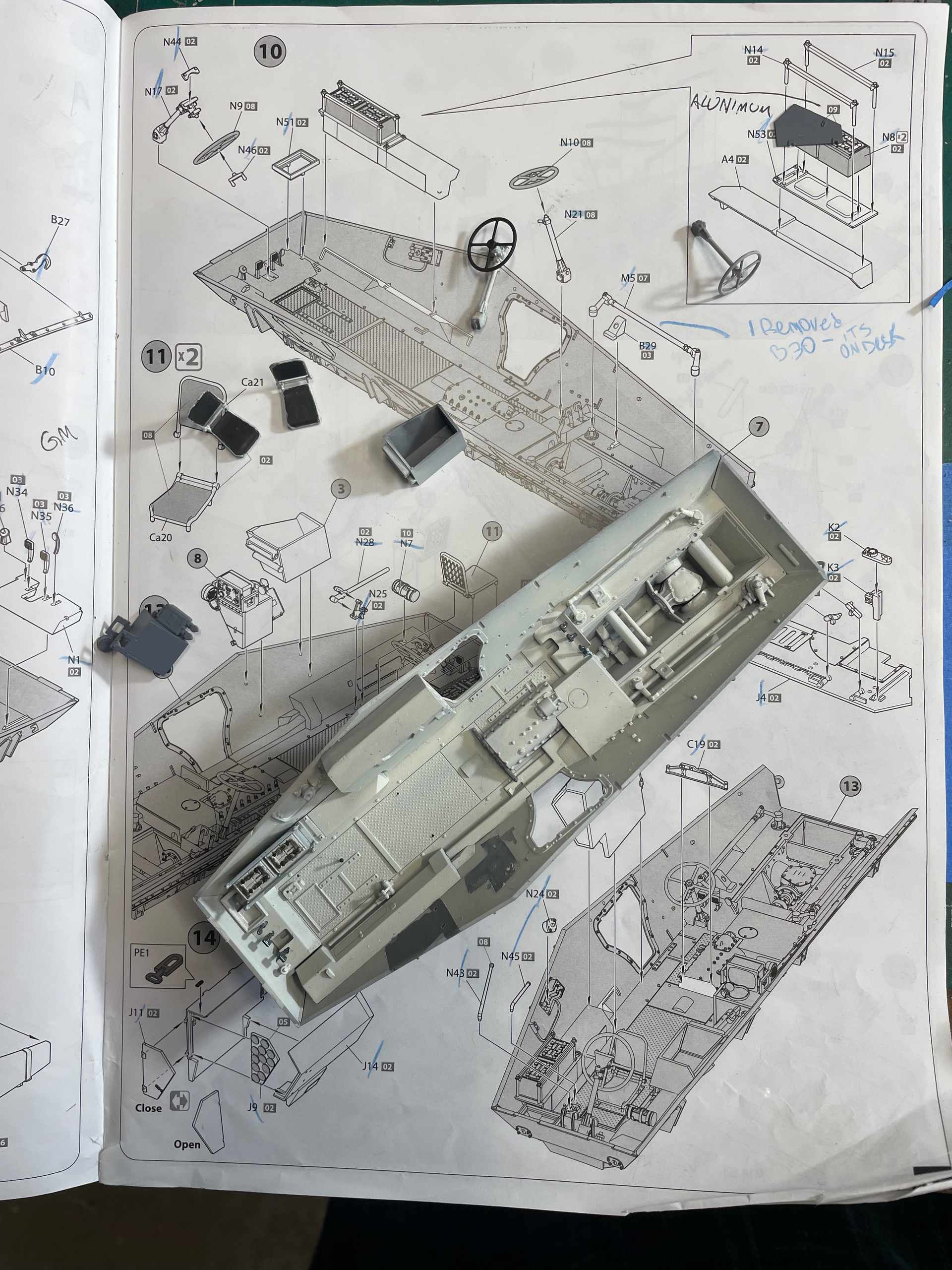
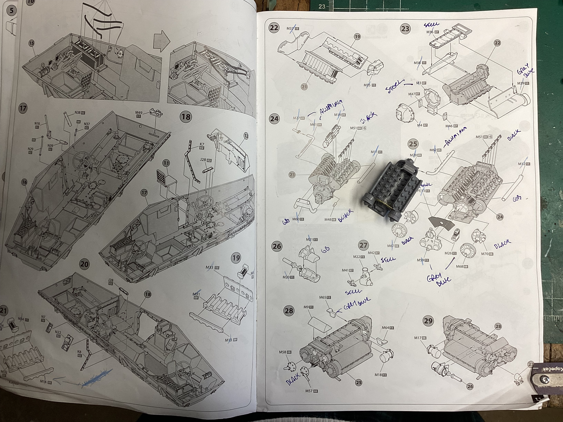
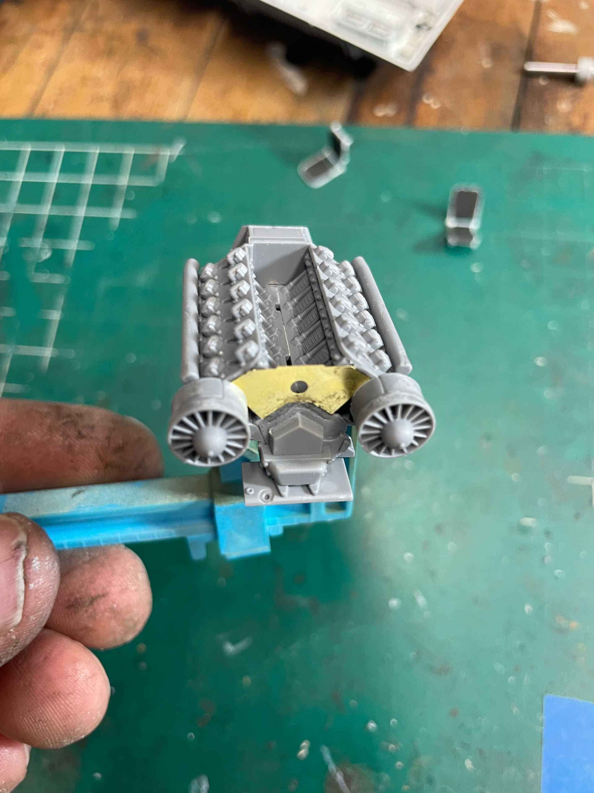
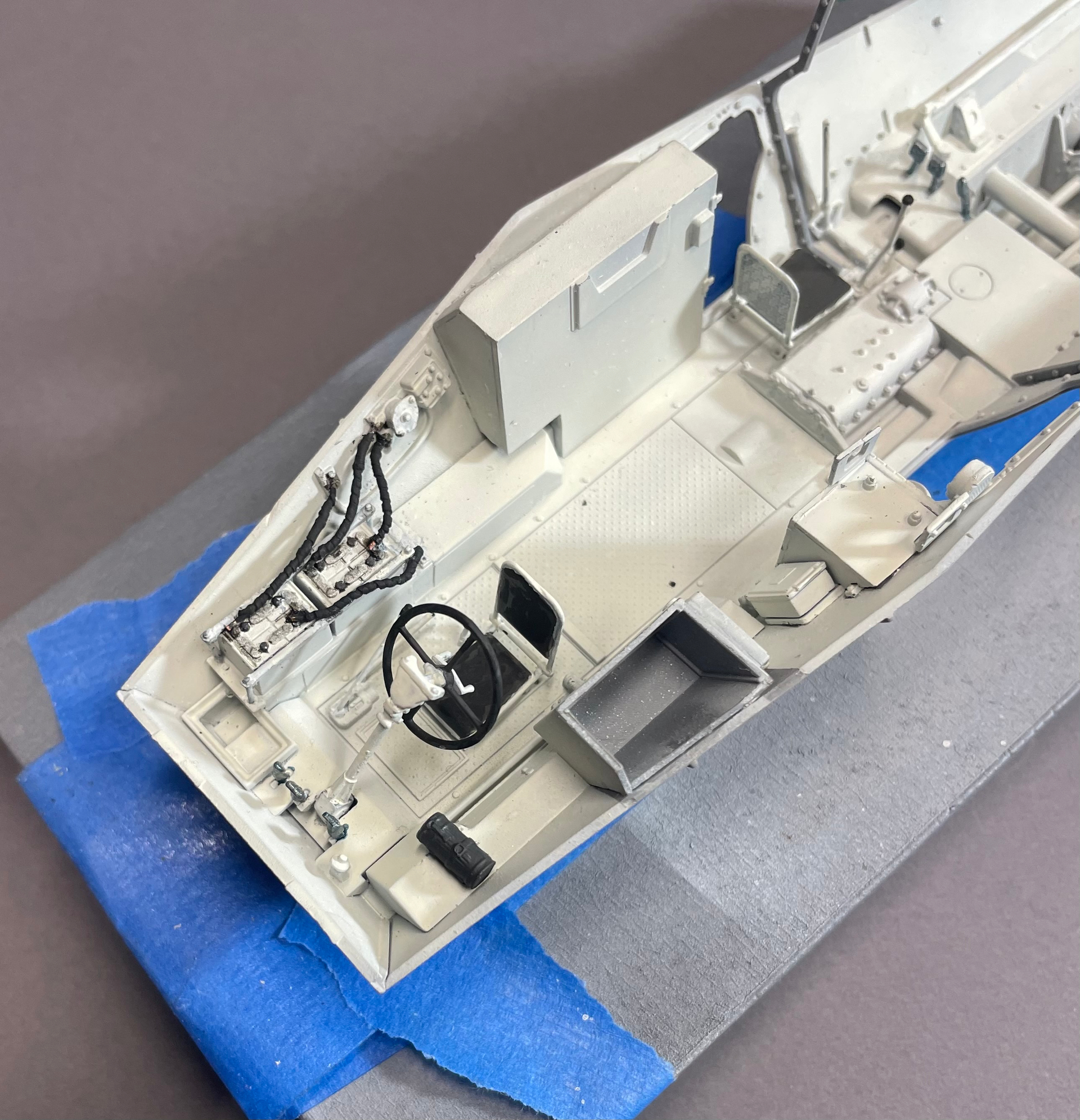
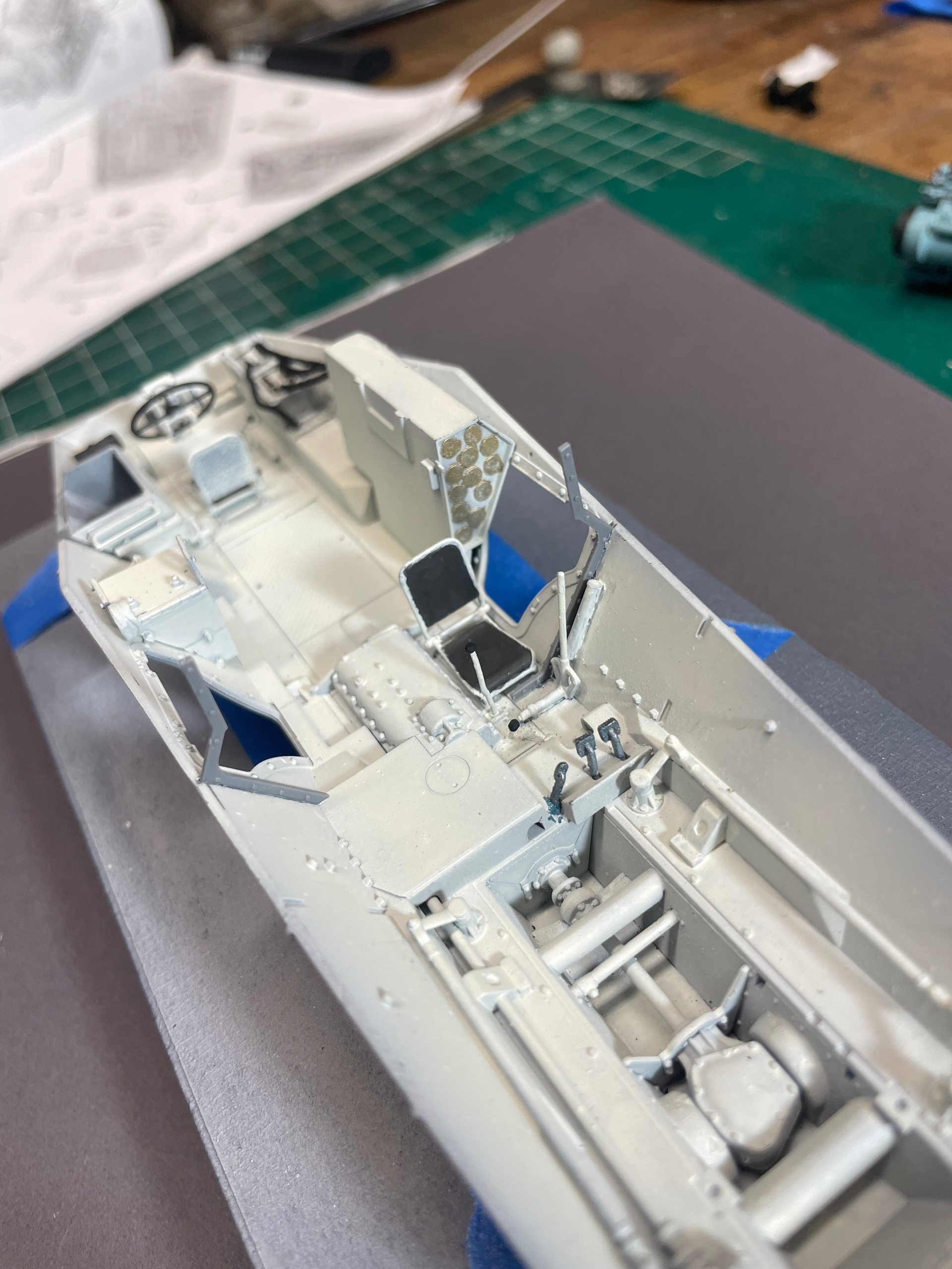
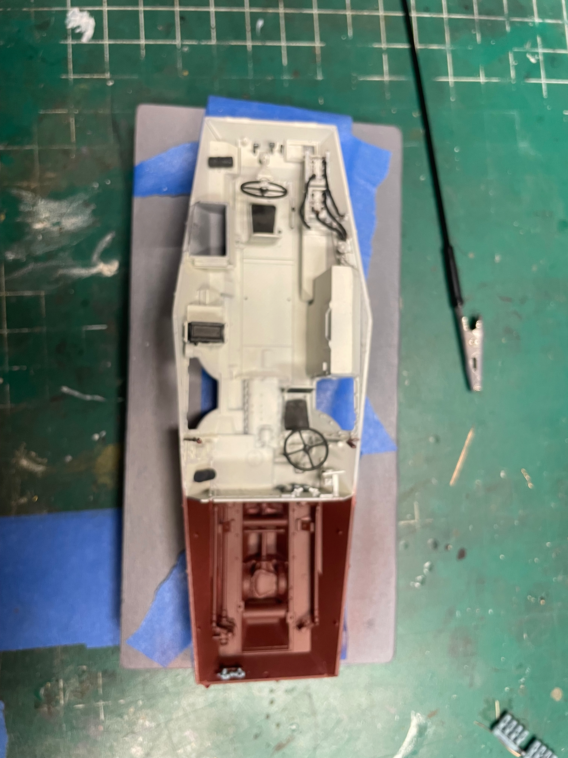
The instructions have you building the lower sub structure first., And a transfer case.

The transfer case assembly ( sub assembly C on the plan) has location points for the assembly on the floor and sub structure sides, but the floor ones are not tight. They have play. The driveshaft has one positive location points for glue, but the other just kind of sits on part B16. I thought it might sit in farther, but it doesn’t.

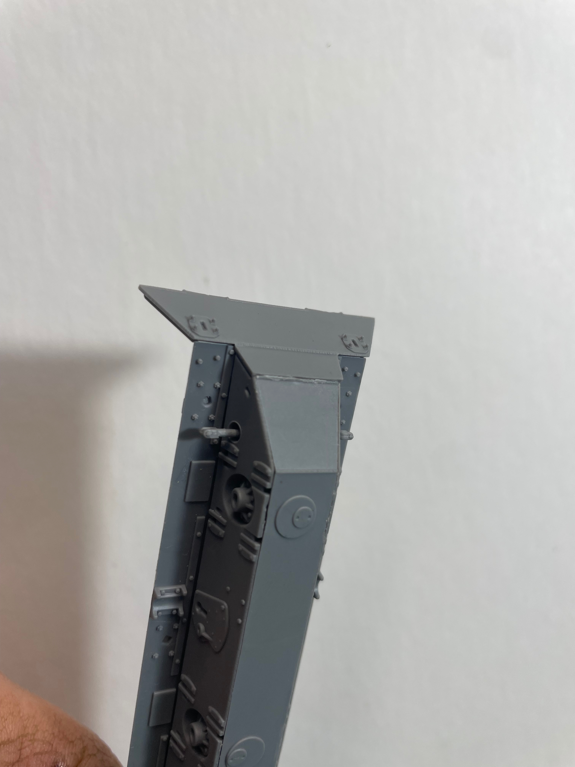
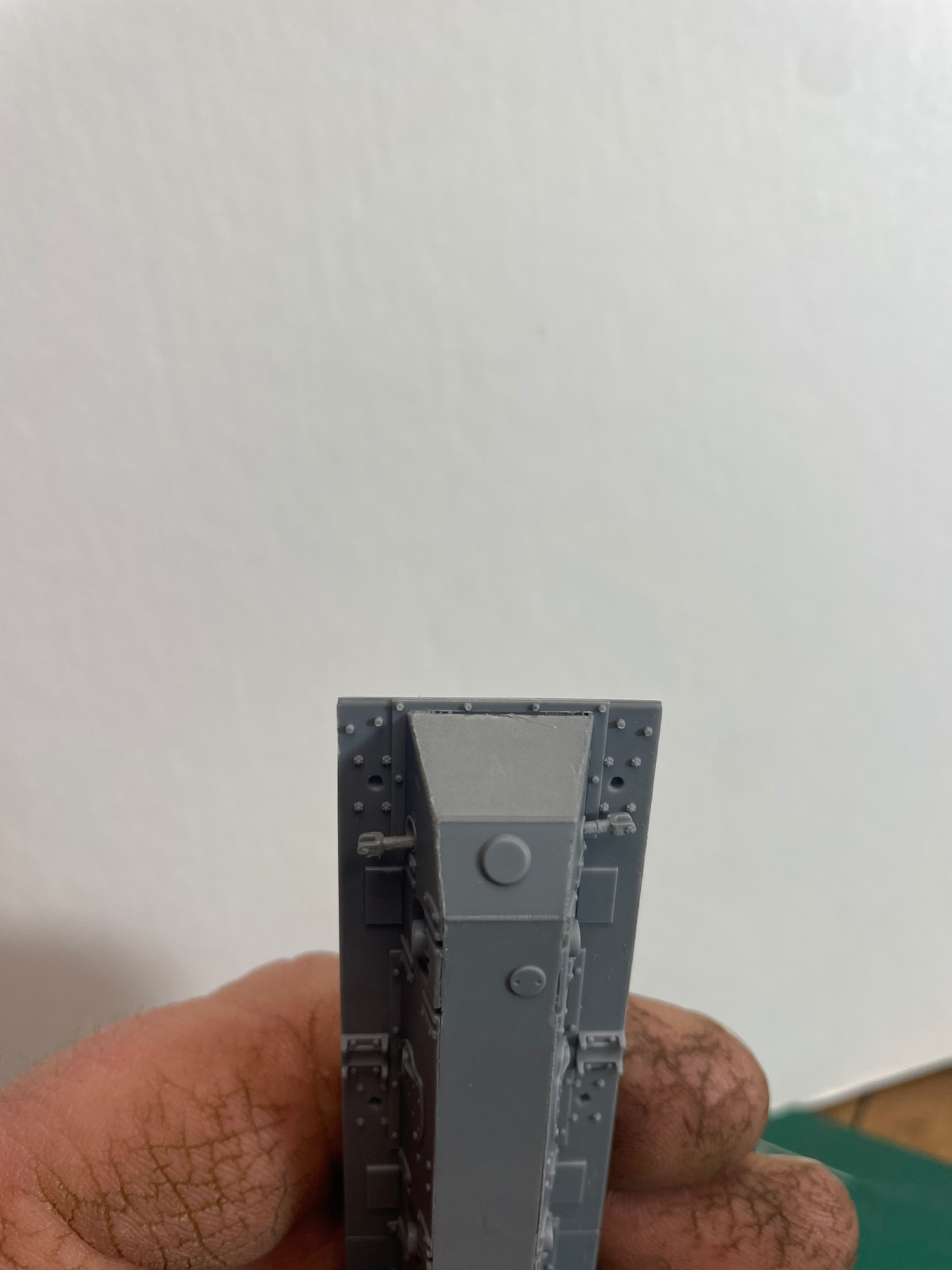
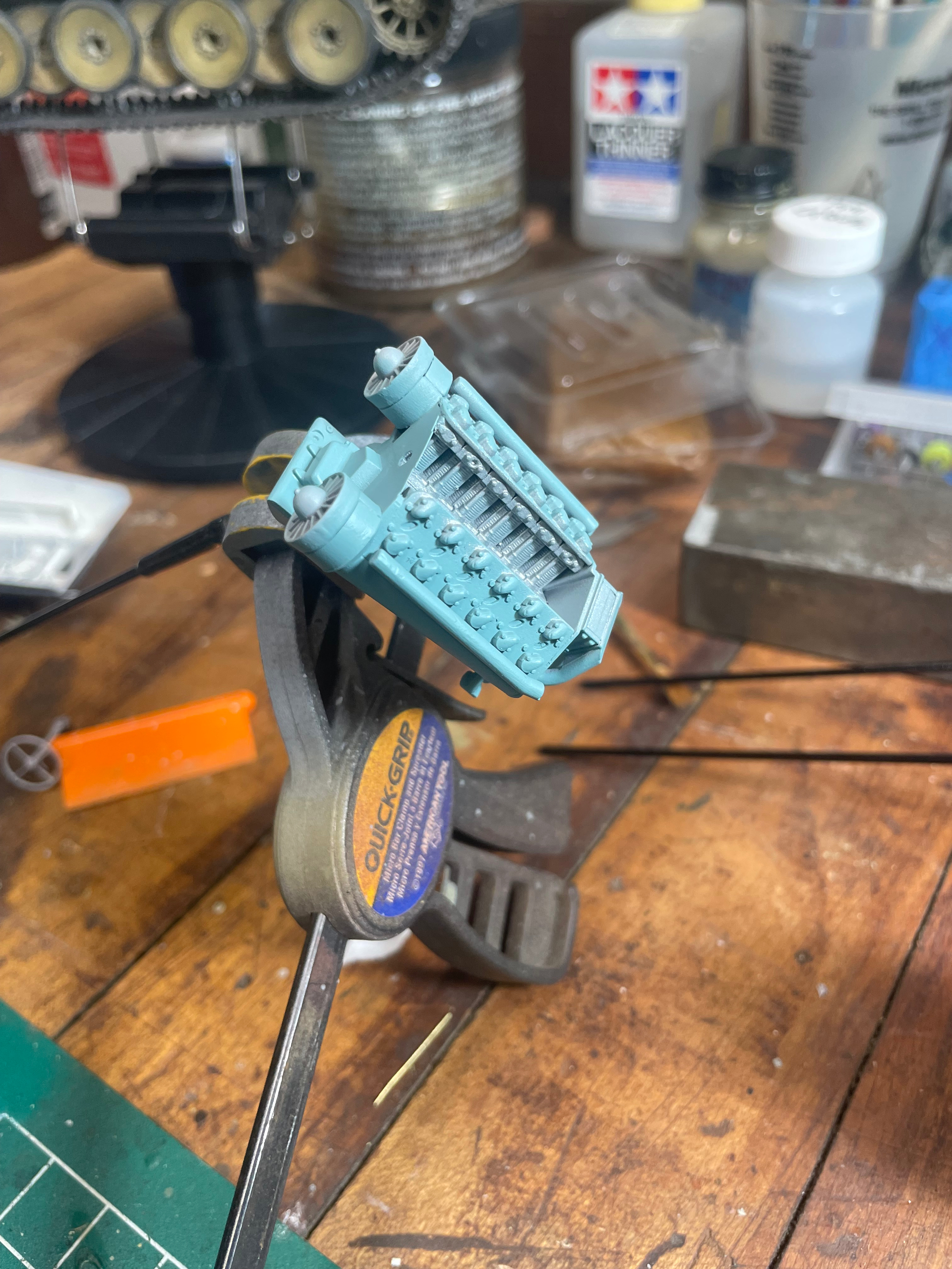
Sub assembly B , the the angled parts need a good sanding to fit properly between the walls of the sub structure. There is a small locator point for proper fit, but it is not a strong location point. It can be a little fiddly to get it. Once the glue hits it, it melts a way pretty fast.

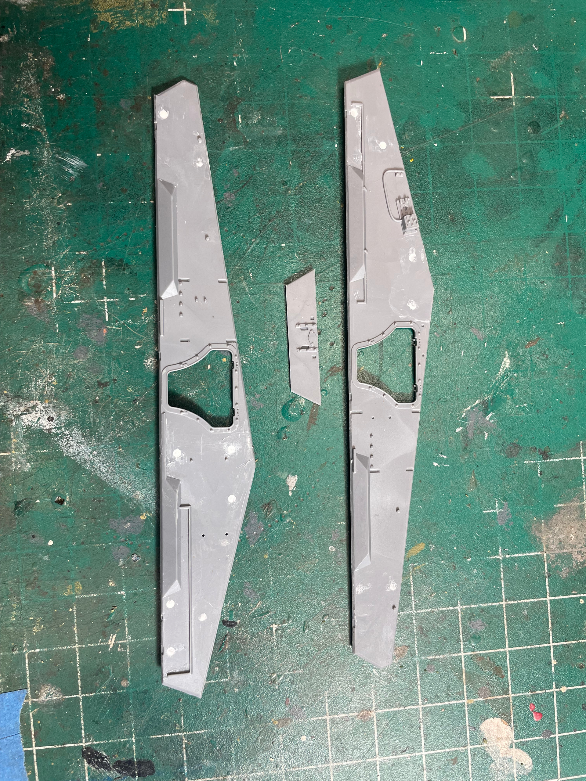
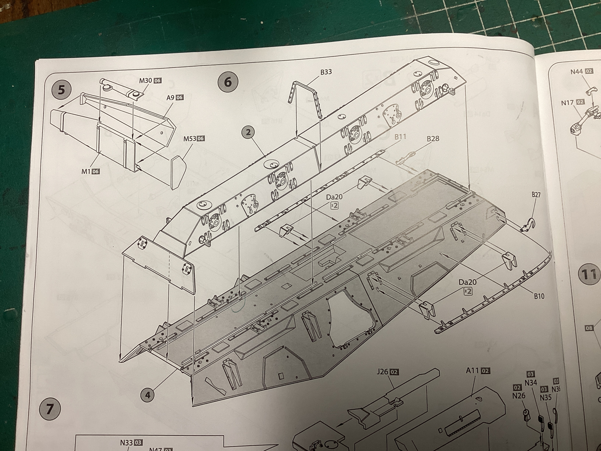
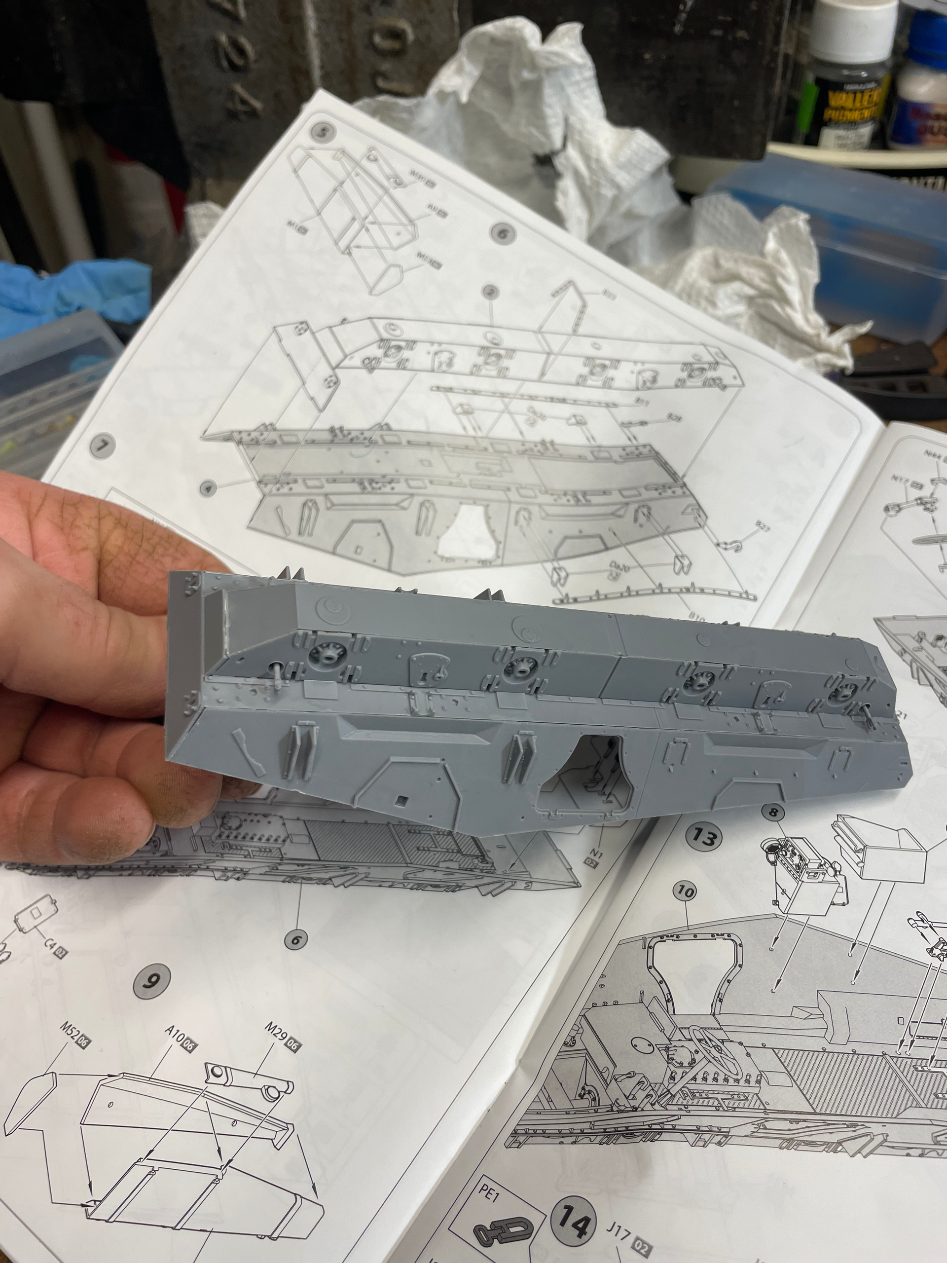
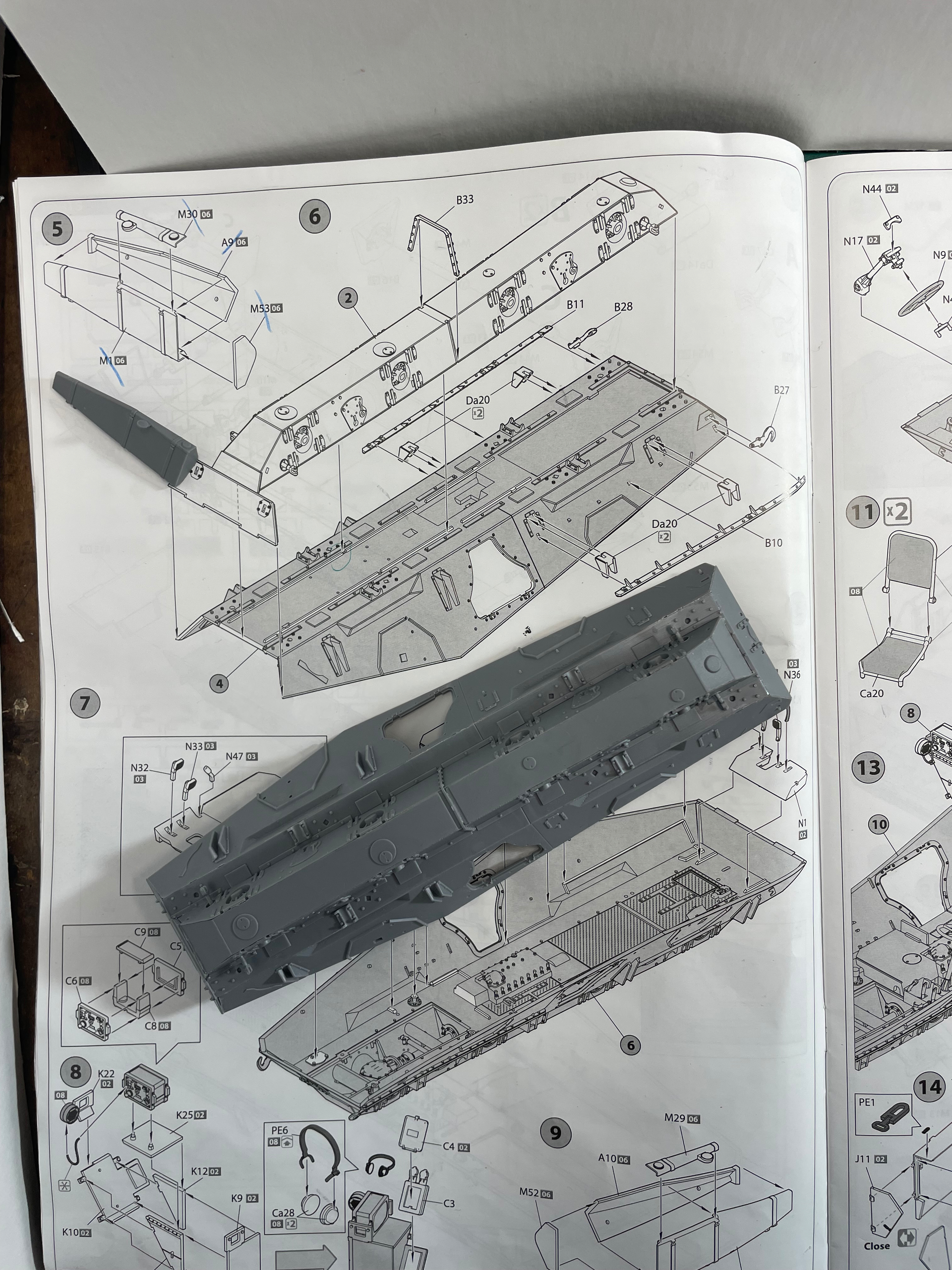
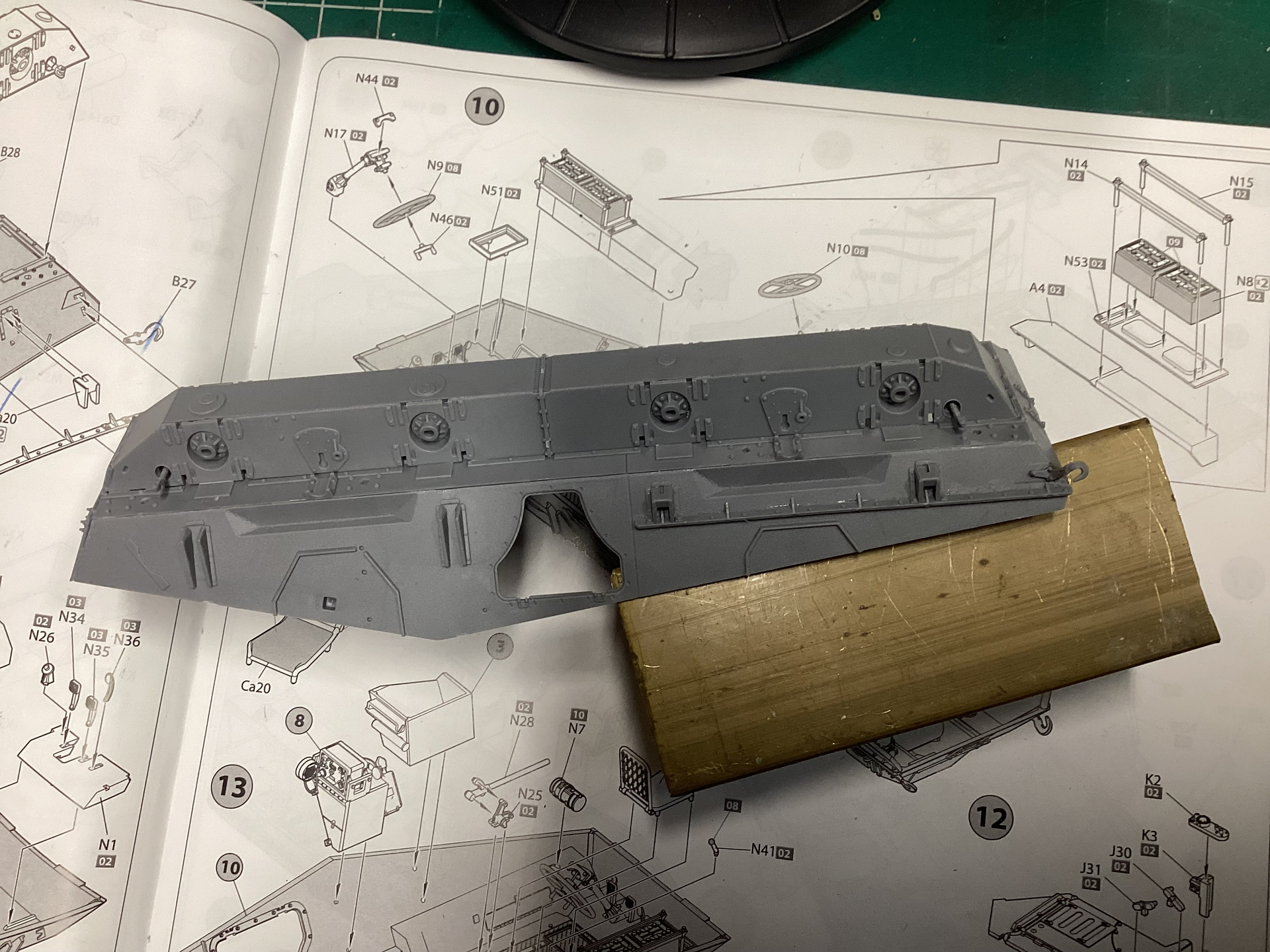
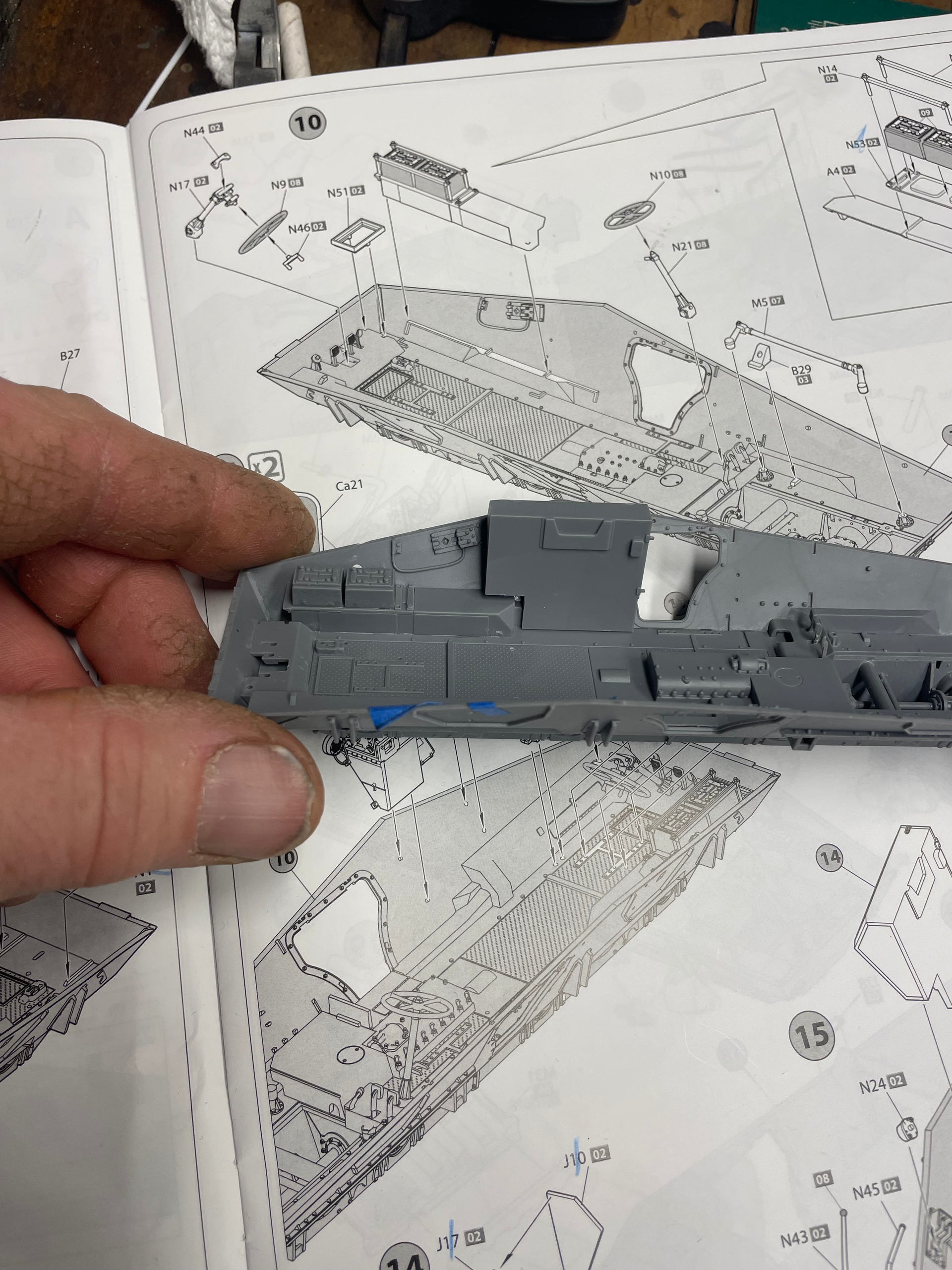
The structure sides are flimsy, but do mount and glues alright.

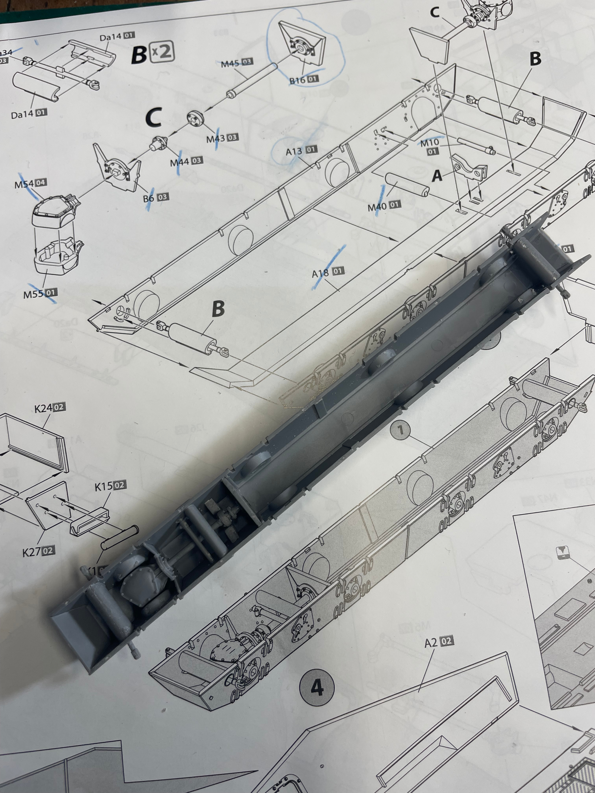
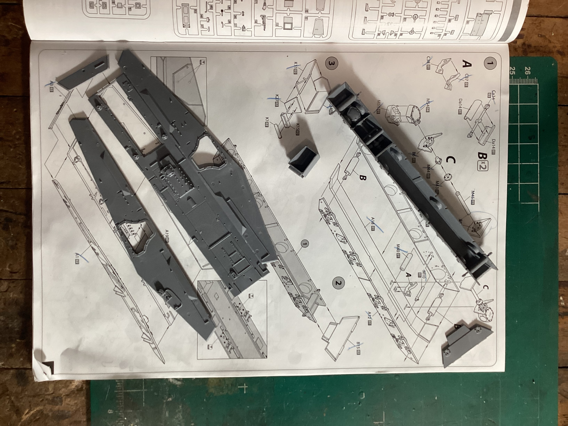
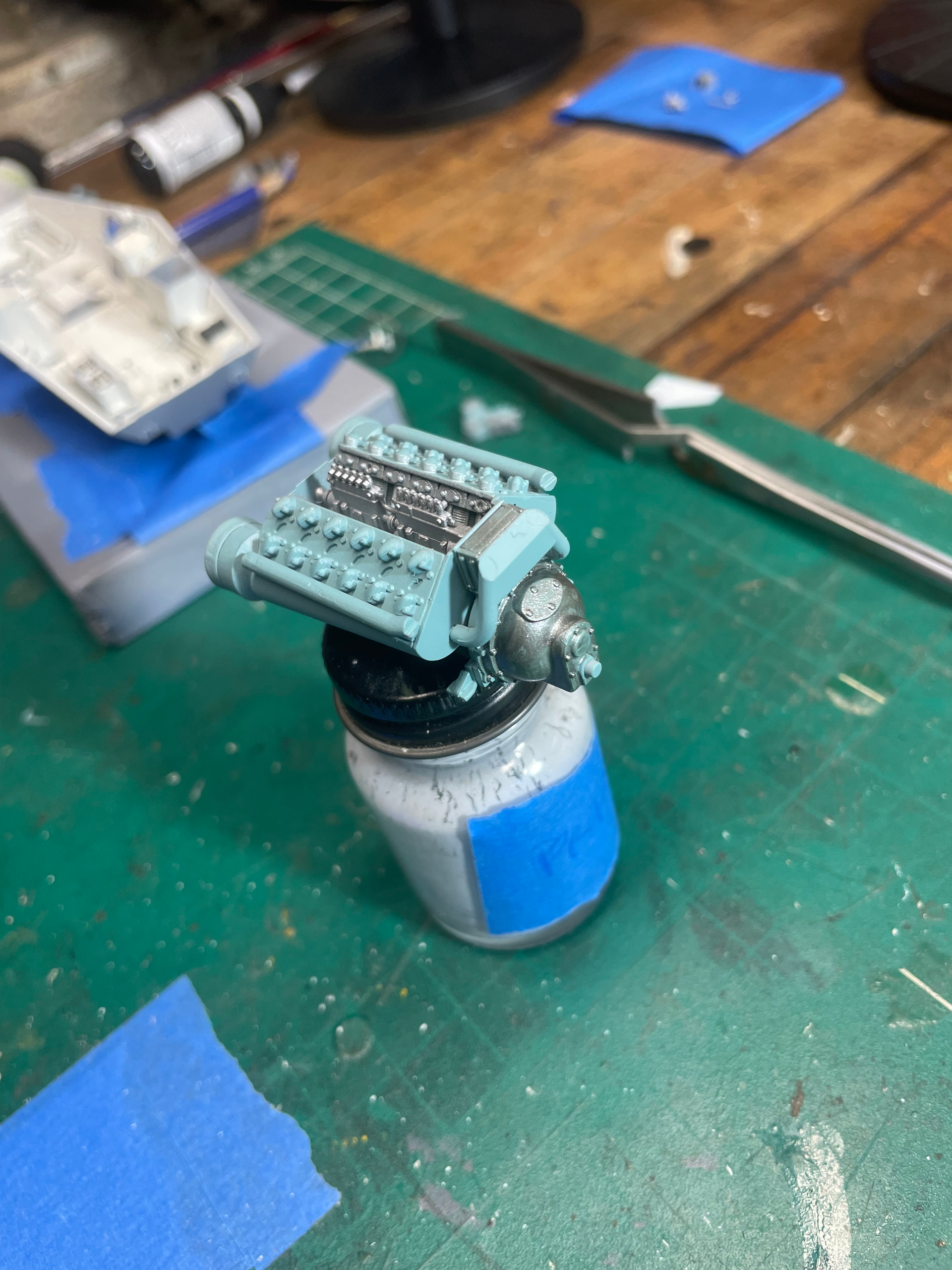
You can see the hull sides for the next step. I stopped there, as it would require thinking to assemble the hull sides in with proper angle. I need to see the best way to do it. No rushing lol.

Until the next update

18 Likes

Thanks for taking us along on your build. I’ve got the Puma and will learn from your efforts!

2 Likes

I hope i can help. I hope i can stay active.

1 Like

Ok, i did a little work yesterday.

First things first, i patched some ejector marks on the interior hull walls. I’m not sure if they will be exposed later.

Step 4 has you mounting the hull sides to the floor, with no real support or clue if the angles are correct. So i jumped ahead and mounted the floor to the sub structure. It easily mounts and adjusts the substructure wall angles for proper placement.

Going into this build, i know i have to pay absolute attention to everything.

I searched out all the small locator parts on the hull sides. ( circled in blue)

You will also see a small strip of plastic ( green arrows ) that help with the angle and keeping proper alignment.

I was honestly expecting the worst when thinking about attaching the hull walls.

It’s a well engineered kit. The flimsy plastic actually helps when assembling, as odd as that might sound. IMO anyways. :+1:

Step 5 is for a sub-assembly.

Step 6 is attaching the substructure to the lower hull, with some additional pieces.

I was hoping to do more updates, but i have fix the fridge.:face_with_symbols_on_mouth:

12 Likes

a man’s gotta do what a man’s gotta do …

3 Likes

Continuing on,

Step 6 has details being added to the outside, lower substructure and hull.

2 parts (B 10 and 11), are long and thin with multiple sprue gate attachments. The kind of parts that instill fear with the knowledge that these part scan break by looking at them funny.

Well, i got them off in one piece with the razor saw. Glued and mounted. The 2 tow hooks (B27 and 28) are very fragile. I already broke one while continuing the build.

Step 7 has you installing interior pieces and a sub assembly for the radio. I kind of jumped ahead starting building some more subassemblies. I need to start painting some of the interior.

I did get to spray some primer .

 What i have learned so far -

The plastic is a little more forgiving than on the T-60 tank i built. But not enough to trust.

I’ve been using some nippers to remove some parts . Well, i got a little to confident and one of the-parts folded.

You can see where i tried to nip the sprue, but it folded the part over and has a small break.

And there are many small parts coming up.

The more i work on this kit, the more i learn on the assembly style, And the more i like this kit. It is just building itself. The kit is becoming less intimidating by the day.

Until the next update,

Marc👍

2 Likes

As you have experienced, not a great option. I would highly recommend using a micro saw blade to avoid more issues especially with Miniart kits. If you can swing it get this set, if not buy the replacement JLC saw blades.

It’s what I use for Miniart, Bronco, AFV Club etc kits that are known for small parts to avoid breakage caused by nippers.

2 Likes

I have been working here and there on kit the lately.

currently, i am cutting, scraping and sanding lots of small parts. They are all for the interior still. A radio, seats, gear levers and such. It’s very time consuming.

I have stressed some of the parts when handling the sprues, This is when i am removing a different part. This piece here, the area of the break was stressed before I went to remove it, i can assume it is from poor fret handling. I tried to glue it before removal, but i failed. I messed up a steering wheel too.

I mixed up a off white Color, and shot the interior and some sub assemblies.

And here is that tow hook that broke from handling the hull. Pay attention.

Hopefully i can cover some of the steps better. There’s lots of planning and painting required if you are doing the full i terior.

3 Likes

When I encounter situations like these I either use a saw
or
cut out a section of the sprue so that the sprue is free to move away
when I cut the gates.

This type of saw is very useful to get into narrow corners where the
razor saw could risk damaging adjacent parts.


The jewelers saw can re-use the broken blades (and they do break until you get used
to handle the saw) from the fret saw.
The coping saw isn’t quite as useful, the blades are thicker and the saw can’t reach as
far into the sprue as the deep bow of the fret saw.

2 Likes

Work has continued on the kit. Like i said, there’s a lot of small sub assemblies going in the interior.

I was trying to see what i could paint beforehand to make it easier. This is my second interior kit, so i am still learning the best way forward.

I have a few more shifters and such to install. I lost 1, an broke another, and haven’t checked the spares collection yet.

While i fight with that, i began making the engine. It’s a multi piece affair, and starting off, quite fiddly.

Trying to get the majority of the engine built so i can spray the base coat and hopefully, prepaint the different colored parts and assemble after.

Almost ready.

Maybe an update tomorrow

10 Likes

Small update.

I forced myself to do some painting.

I didn’t have much time today. Just parts cleanup.

12 Likes

For the record, i am not really using any references for this build, except for what i find on the net. Other than that , i am just using the instructions.

I found pictures of a Tatra engine at the Panzer Museum. Granted, i am sure the engine has been refinished, but the paint instructions don’t totally match.

I am also kind of sure that the engine area is not painted in off white.

In the instructions, They show red brown in the small area where the differential is mounted. But still show the off white for the rest f the compartment.

Maybe i can research RFM instructions? What do you think ?

Edit: this video has a few interior shots. Not for colors , but ideas of what it looks sort of like.

1 Like

I’m not seeing interior paint scheme in RFM instructions.

I think i’m going to base it on the PZ museum engine , and some b&w photos i saw.

1 Like

Here’s a site with close ups of the Munster Museum 234/4 vehicle.

2 Likes

I’m finally getting closer to finishing the lower in hull.

I procrastinated a few days. Trying to make up some battery cables. If you browse the kit pictures, you will see the builder added copper wire. Then in another picture, they were an armor wrapped cables. (234 series) Photos for reference only.

I cut up and laid out some copper with the proper lengths and bends, somewhat😃.

I then flattened the wire and wrapped it around the “ battery “ cables.

It’s a first time i really put an effort for that. With the reference in the instructions for a basic layout, it wasn’t too bad.

Unfortunately the pics aren’t in order, but you get the gist of it.

Most of the lower driving compartment should be completed soon. Some touch ups needed, need to install the last steering wheel and a firewall.

Engine work has continued, but i still need to add many small parts.

And then i might try my hand at plumbing the engine. I need find some small wire.

Marc

12 Likes

Excellent detailing Marc, and a wonderful build so far. You are doing great work. It’s looking fantastic.

3 Likes

Thanks for the confidence boost .

1 Like

Well, i have been working on this a couple hours a day on the weekends.

Sprayed rotbraun in the engine compartment. I know the ivory was incorrect. I was going to add a few steel colors, but i chose against it.

the lower hull interior is really ready for a clear coat.

I’m killing time trying to plumb the injectors on the engine. Or i should say i am killing myself trying to do that. This is the first i have tried this. If you look the 234 series at the Miniart website, they have some pictures of the injectors installed. Theirs is nice and neat. Mine looks more like a jerry rigged type of thing lol. I’ve broken a few drill bits, and , since it’s very thin copper wire, it is extremely difficult for my big fingers and poor eyesight. I do one or two, then take a break . It’s exhausting. But i’m going to do it.

No Retreat!

Marc

11 Likes

Well, i am still here. I’ve been very busy.

It’s a small update to show that i haven’t given up.
I have stopped production to continue with the plumbing of the engine. I am so close to being done ( with the injectors :slightly_frowning_face:) with it.

i knew this was going to b difficult for me. But It’s more difficult as i went on. You would think it would get easier, but no, not for me apparently.

Working with this small wire has shown me it’s time to replace my tweezers. They’re not too old , but i abused them.

That bent one that connects all the injectors to each other.

It is tough. I’ve tried drill bits and different tricks to help hold it while mounting it, but it amounted to a good 5-6 broken drill bits.

Well, hopefully i have a better update soon.

Until then ,

Marc

13 Likes

so, i sat at the bench. I picked up the engine, scanning between it and som pictures i am using fo reference. I have 2 small hydraulic lines to connect. Free hanging type of things to connect with very little glue/ connection surfaces. I decided to wait.

So here is the latest update.

Then i can mount it in the hull, an add a few more lines in.

I have my work cut out for me.

Until the next one.

Marc

9 Likes