Hello model builders
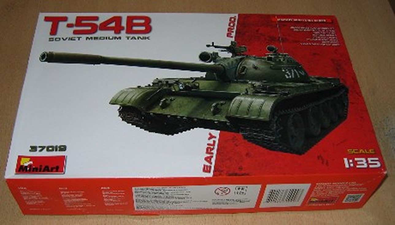
As I announced with the BREM-1 topic, I’m continuing with a new topic: armored bridge-laying vehicles. This is the MTU-12 bridge-laying vehicle, which was used in the Warsaw Pact armies. The MTU-12 was also used in the East German National People’s Army (NVA). Development of the vehicle began in the 1950s, based on the T-54. The MTU-12 remained in service with the GSSD units, alongside the MTU-20 and MT-55 vehicles, until the 1970s. The model is built using a T-54B kit from MiniArt and tracks from Friul. Everything else is scratch-built. I’ll start with some original pictures.
The kit used
15 Likes
Great project there. I like the style of the vehicle, but the Fachwerk would scare me. Good luck and I follow your progress.
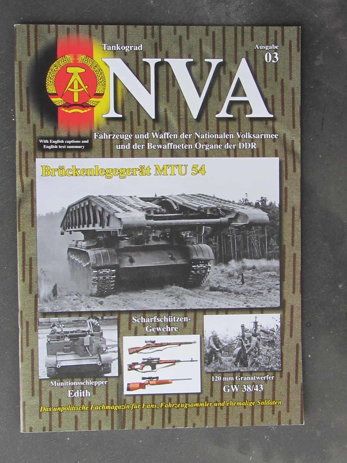
P.S. if you need more references, there are some more pics in my NVA books.
1 Like
Hello Hans-Hermann
I’d be interested to know which NVA books you have.
1 Like
Brilliant project that I shall be following.
1 Like
Another subject from my to-build list!
And a build I will follow closely.
Joachim,
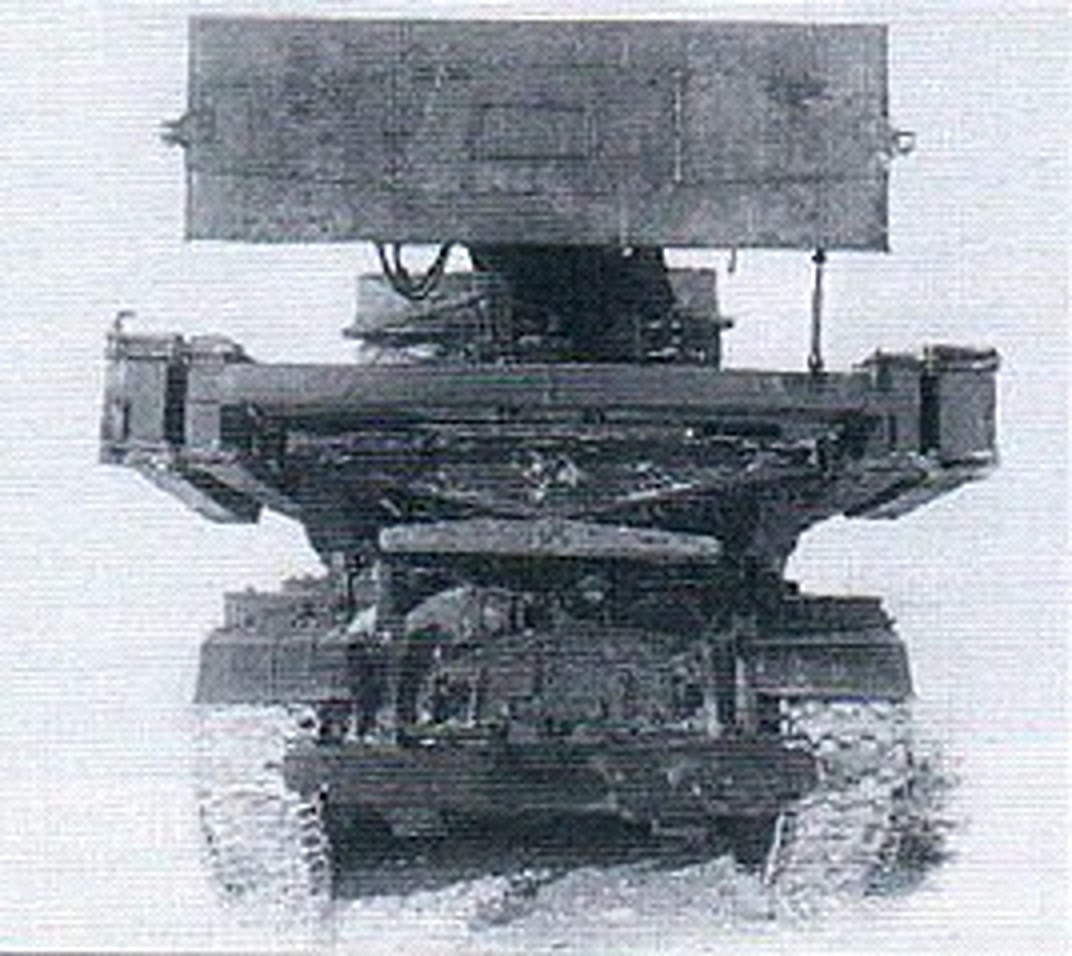
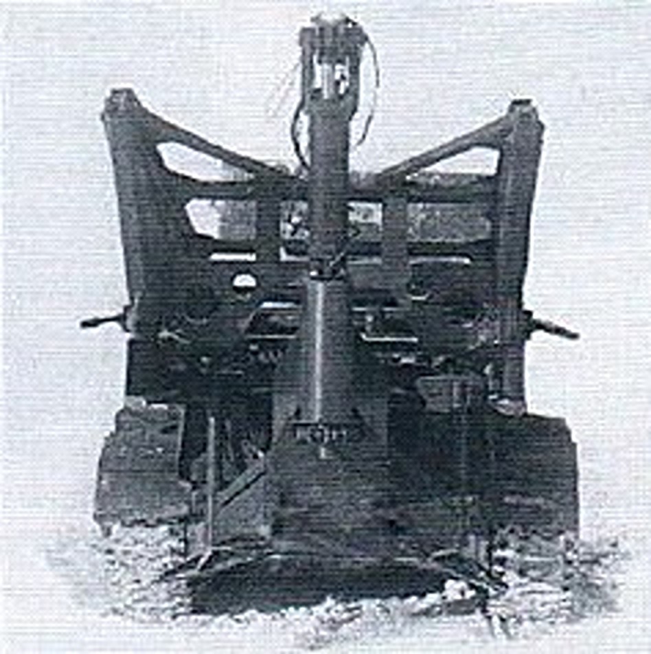
I managed to take some close-up shots from the specimen in a Bulgarian Army Engineer unit museum, so I can share them if you need additional refferences.
Here is one as a sample:
Cheers,
Angel
3 Likes
Lots and lots and lots of teeny tiny pieces to shape and glue into the correct position.
Model builders must be crazy …


2 Likes
This is madness! L-shaped braces are a hell to build.
1 Like
Hallo Joachim, I have Fahrzeug Profile 95 Brückenleger der NVA. But you probably have it yourself.
1 Like
Thank you for your offered help. It would be great if you could share relevant images on this topic. I think this might also be of interest to other modelers who don’t have the relevant images.
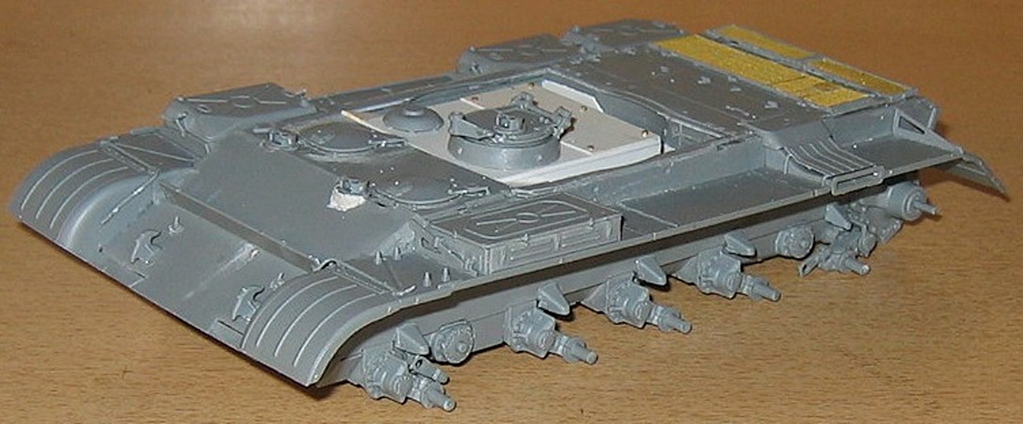
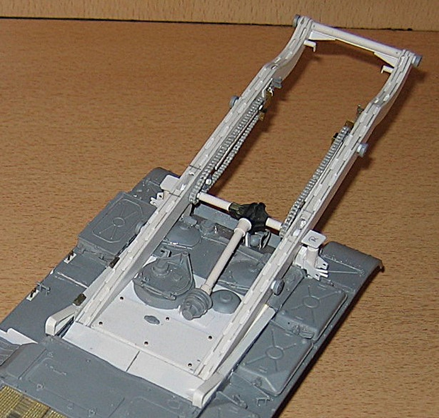
Construction began with the construction of the base vehicle. A lot of modifications are required on the upper part of the tank hull. The driver and commander sit side by side in the vehicle. This means that the driver’s hatch is mounted twice in the roof of the hull. The gunner sits in the middle behind it, where the parts of the loader’s hatch from the kit can be used. The accompanying anti-aircraft machine gun is identical to that of the T-54B and can also be used from the kit. The hull roof must be cut out so that the spars of the bridge’s support frame can be retracted there. This is necessary if the bridge is still being installed on top. Furthermore, the cable winch for raising and lowering the support frame is mounted in the rear part of the recess. First, here are some pictures of the original and the model to explain this issue. If you have any questions, please ask.
Greetings, Joachim
The construction plan
8 Likes
Yes, Hans-Hermann, I have those notebooks and books too. Nevertheless, thank you very much for your offered help.
2 Likes
Joachim, do you have this also?
2 Likes
Yes, Hans-Hermann, I have this booklet too.
1 Like
That’s going to be impressive.
1 Like
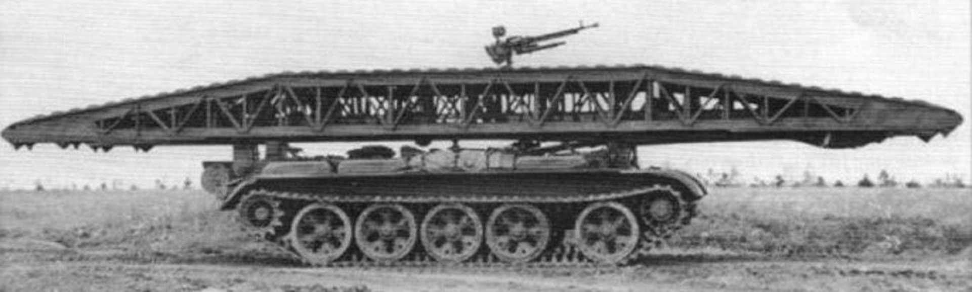
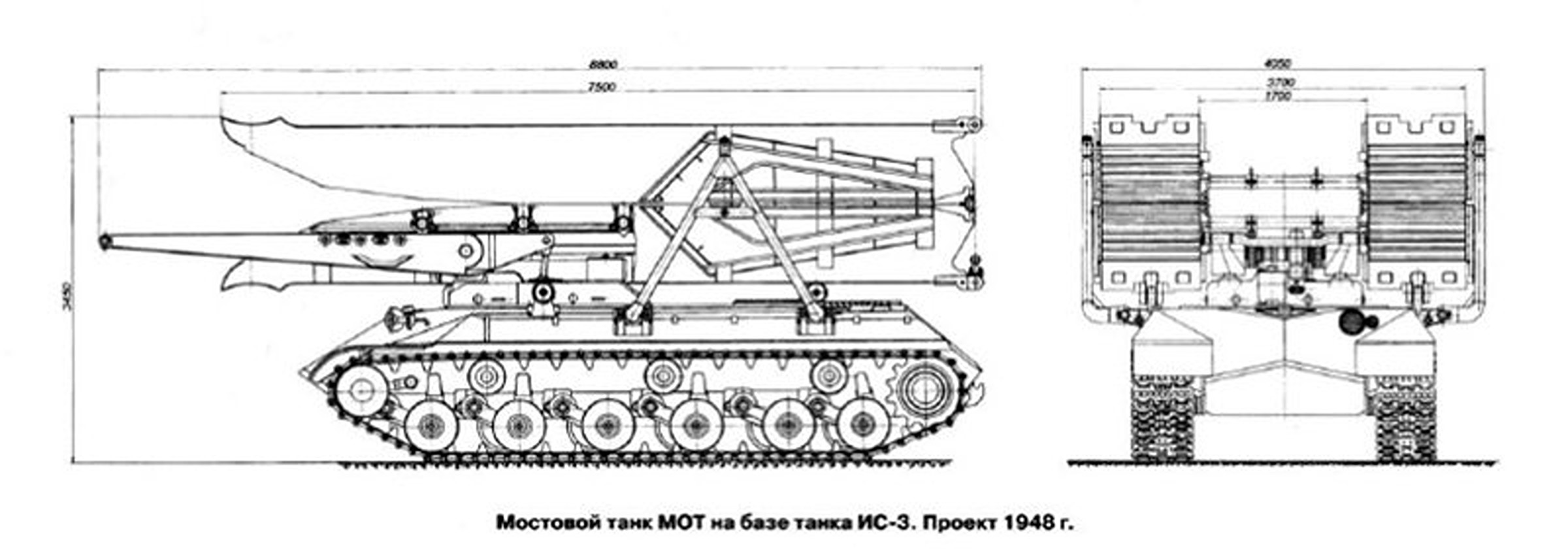
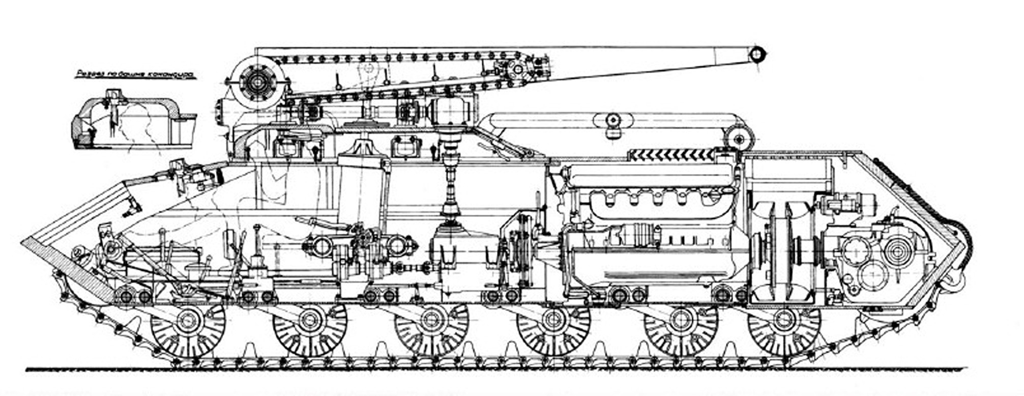
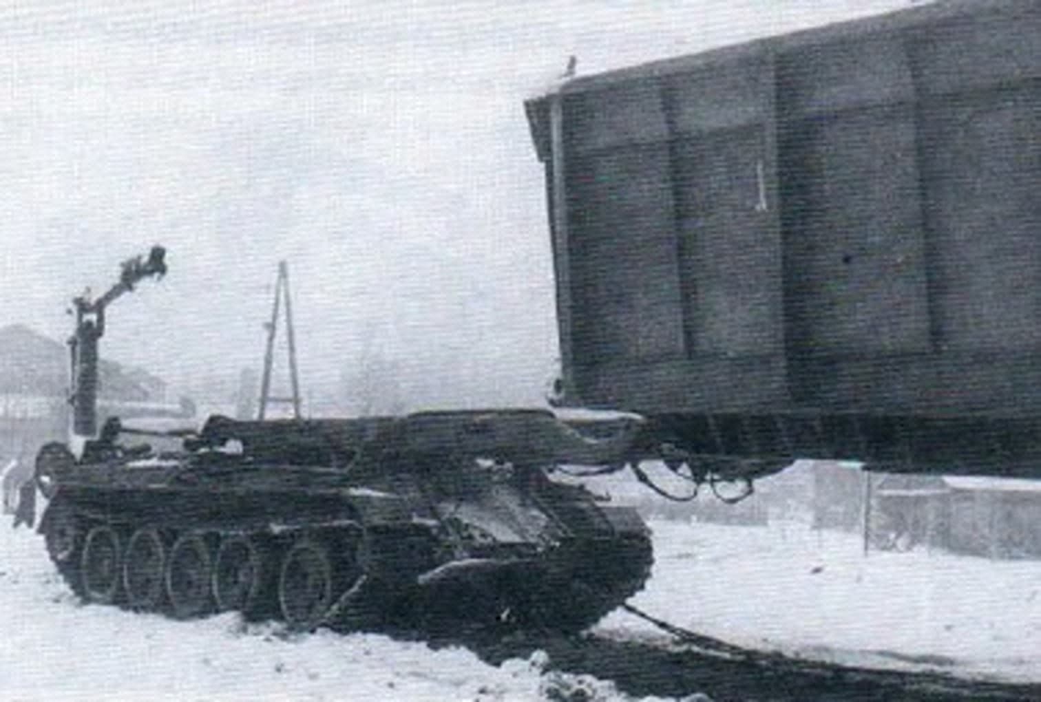
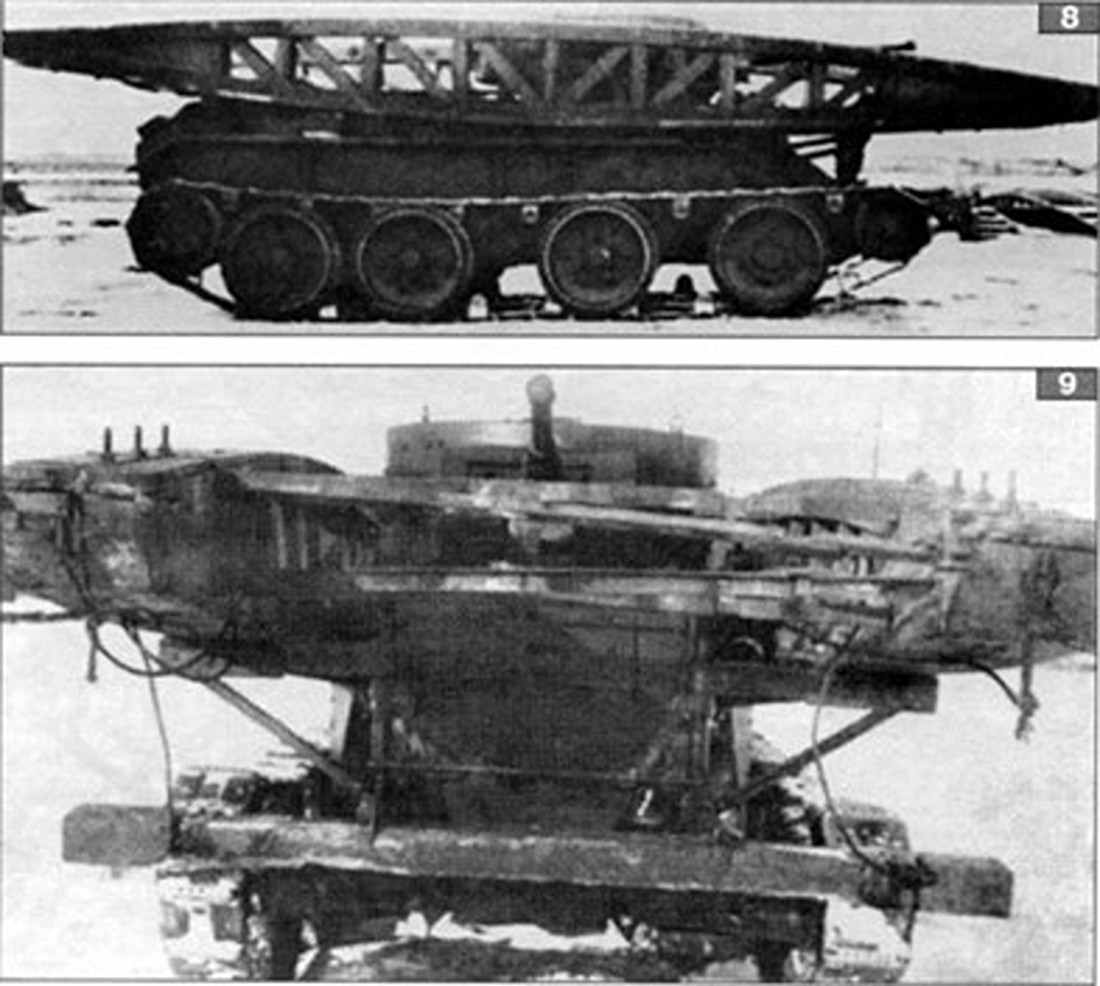
The development of the MTU-12 armored bridge-laying vehicle is a comprehensive topic that you might want to know when building a model. That’s why I’m going to address the topic here today. The idea of developing an armored bridge-laying vehicle already arose with the introduction of the first T-54 tanks. This is also evident in the blueprint shown, as the two machine gun pods on the right and left of the track cover were still installed and equipped with the round additional hoppers on the right and left rear. This was the starting model for the later development of the MTU-12. At the same time, bridge-laying vehicles were also being developed based on the JS-3 heavy tank, which probably never saw service. It would, however, be an interesting project for model making. MTU-12 means bridge-laying vehicle with a 12-meter bridge, but these 12 meters were too short for the military. Therefore, new projects with longer bridges, of at least 18 meters, were constantly being developed. The idea of underwater bridges also played an important role. The armored bridge-laying vehicle remained underwater, while the crossing vehicles drove over it. This 18-meter bridge length was also crucial for the design of the MTU-20, MT-55A, MT-72, and BLG-60 bridge-laying variants. The idea came up to attach a second bridge to the MTU-12 on a transport trailer. This made it possible to install the bridge twice. Here are some photos and drawings to accompany my contribution.
Best regards, Joachim
5 Likes
I want to see the scratch built launching mechanism(s) so I can try and build similar to improve my IT-28 Bridgelayer build.
1 Like
A lot of material was lost due to a computer crash. I’ll try to answer the relevant questions anyway. Here’s some history and IT-28.
2 Likes
After describing the development of the MTU-12, I’ll move on to building the model. To avoid this becoming a long-term study, I’m skipping various construction phases. I continued with the construction of the laying arm, which was cut from plastic and glued together. The many recesses in the surfaces, which I wanted to represent at all costs, posed a problem. I used an axle from a ZIL-151 truck to drive the tracks for transporting the bridge. This axle was modified for this purpose, just as it was done on the original. Since I couldn’t get hold of suitable tracks, I had to resort to the small tracks. I had to make this compromise. The locking devices, to the right and left of the pivot point of the bridge’s support arm, were also installed. These hold the bridge in position while the armored bridge-laying vehicle is moving. I’ll show how this works again with original pictures. Now for some more pictures of the construction.
5 Likes
Very fine scratch building and super helpful for my project.
2 Likes
I guess this is a transfer case (arrow)? Something will lead out from under the top deck?
1 Like
Ehrfürchtiges Schweigen meinerseits. 
2 Likes