Hi all, it’s been quite some time since last I posted in KMF, sort of lost my modelling mojo and am now trying to regain it, .
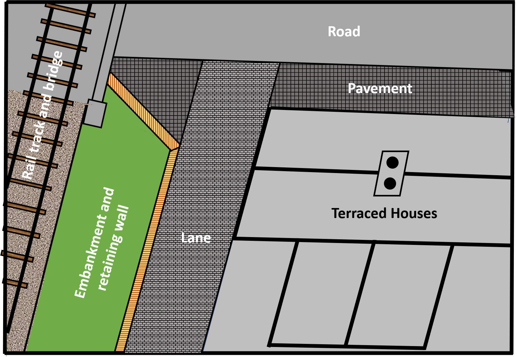
I am trying to work out sizes etc for another small (A4 size) 00 diorama. I’m imagining a WW2 era British city/town scape, a partial row of Victorian terraced houses, road passing under a railway bridge. There will be a partial embankment and retaining wall (see rough sketch below (Plan 01)).
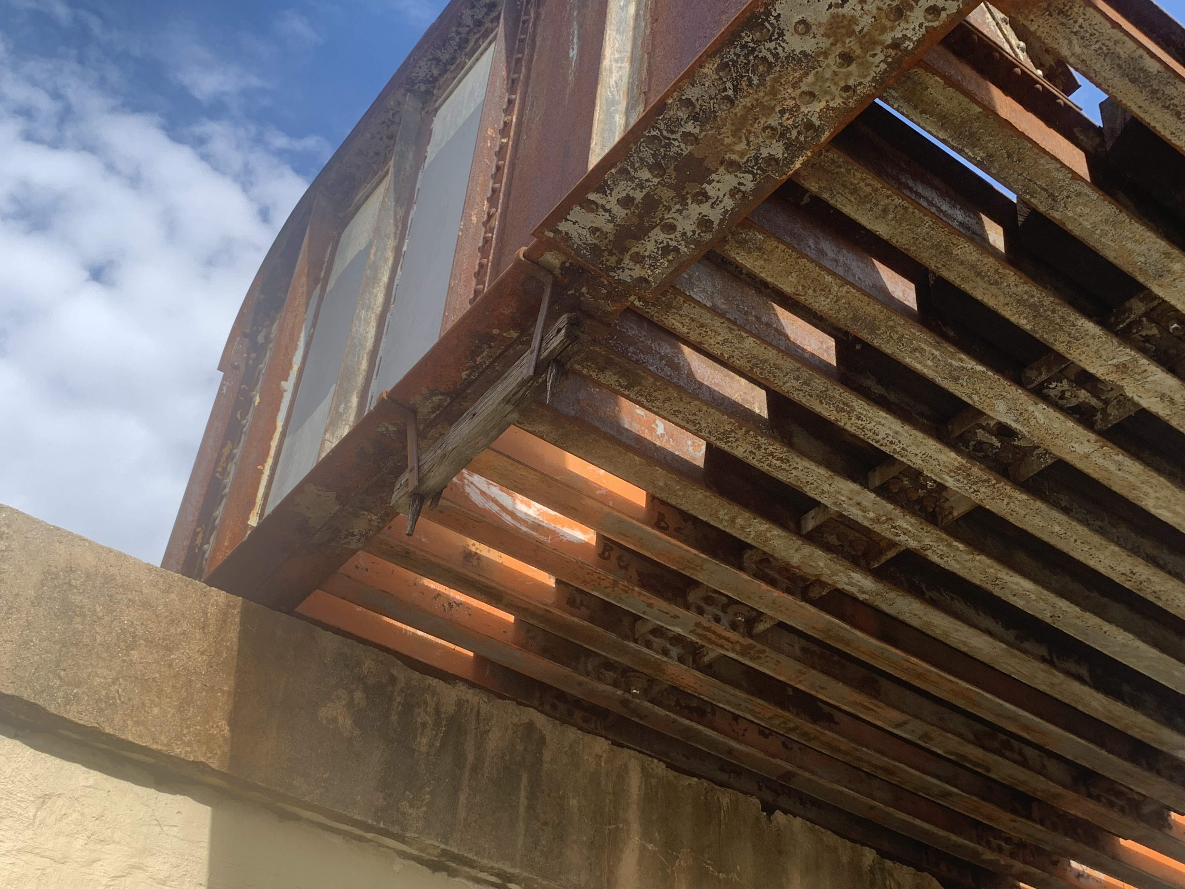
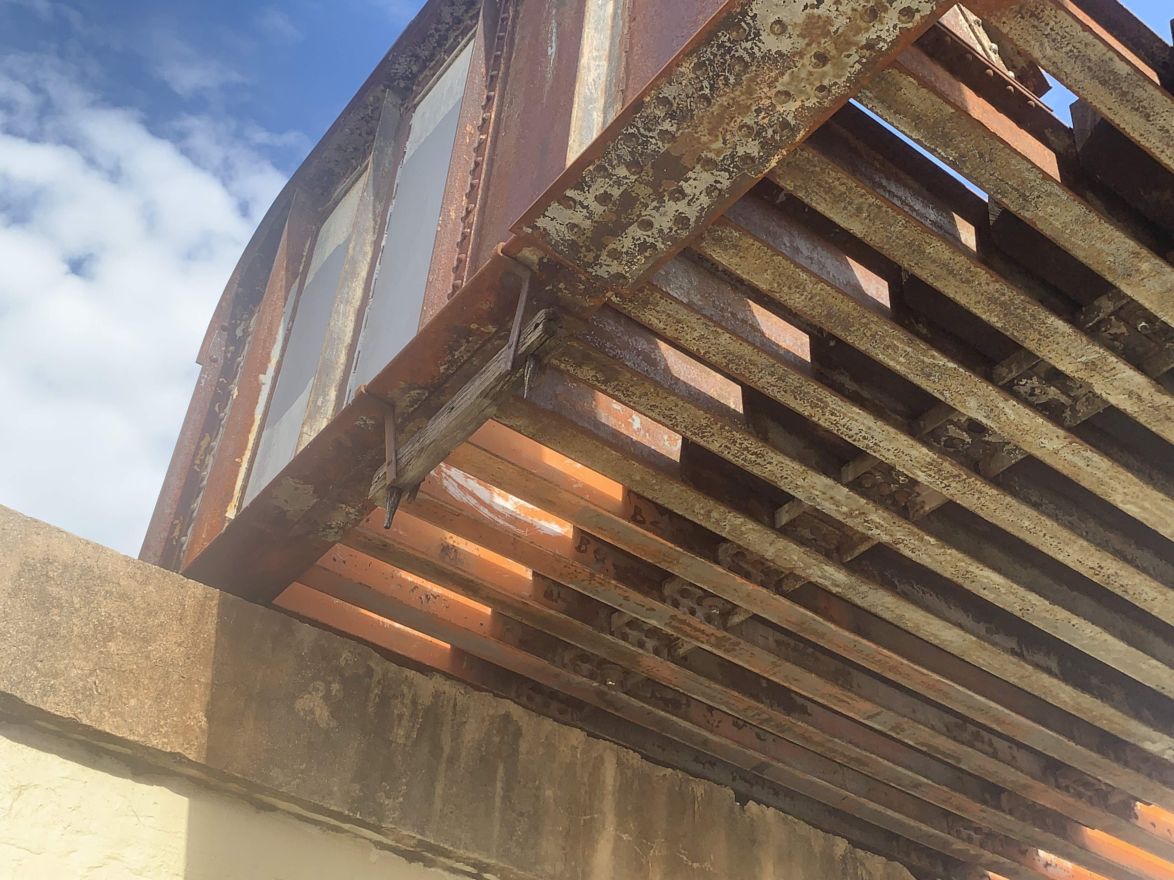
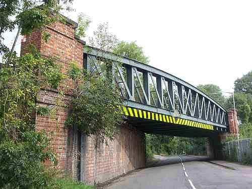
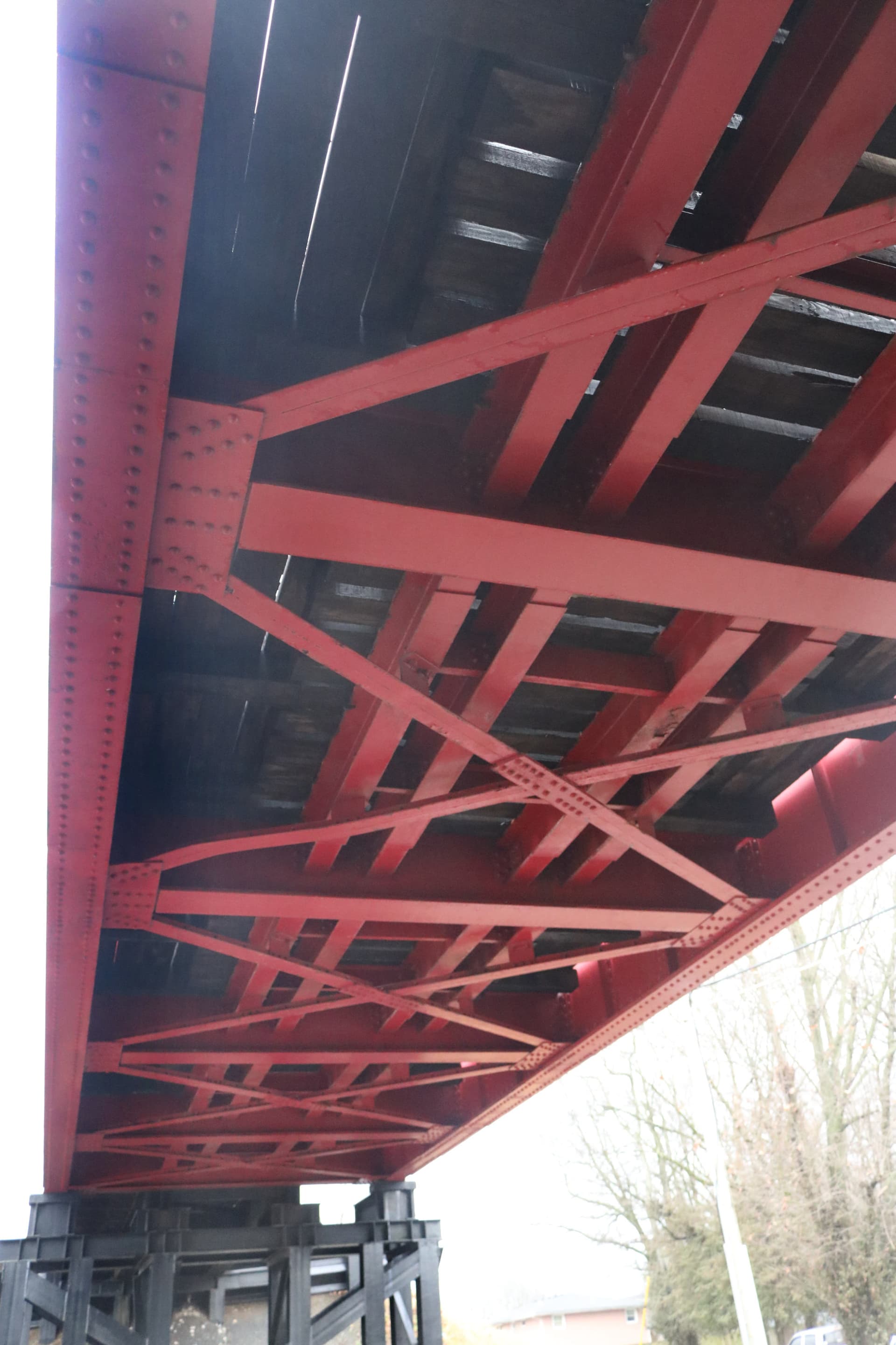
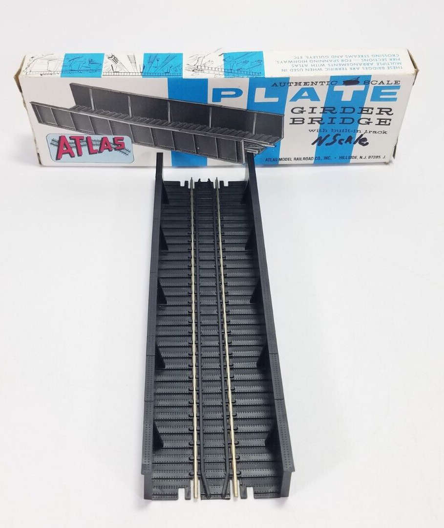
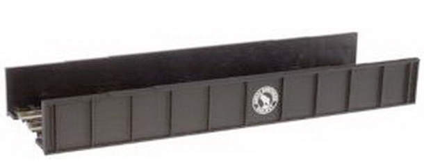
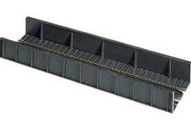
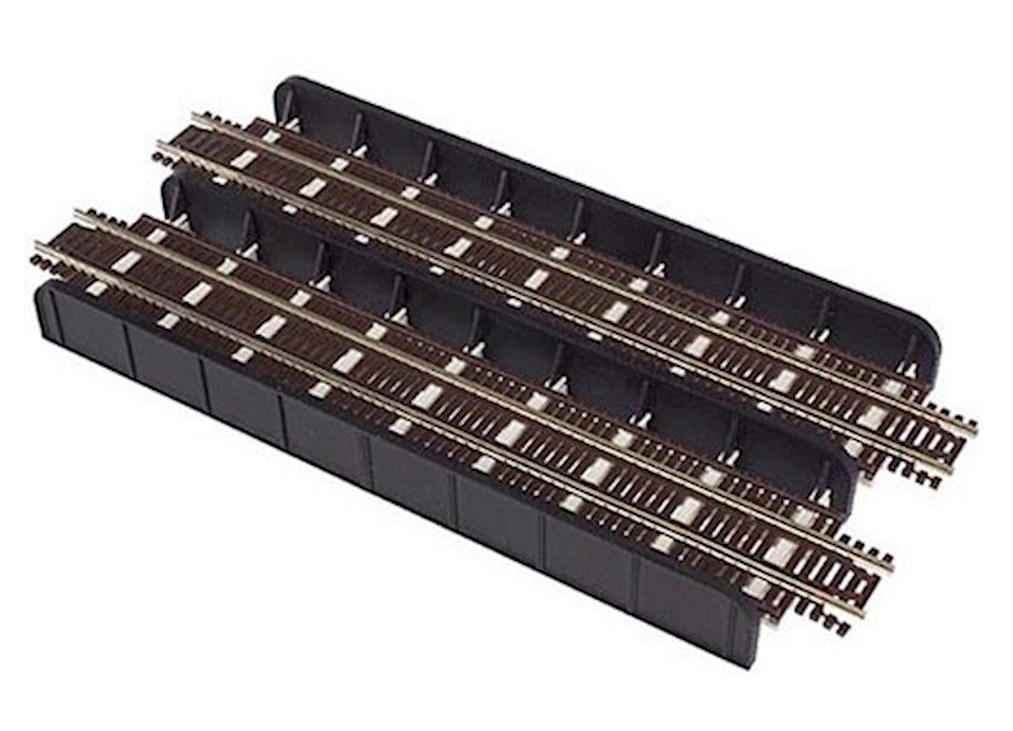
The partial bridge will be scratch built and will be a steel through girder type, which I think would be okay for WW2?
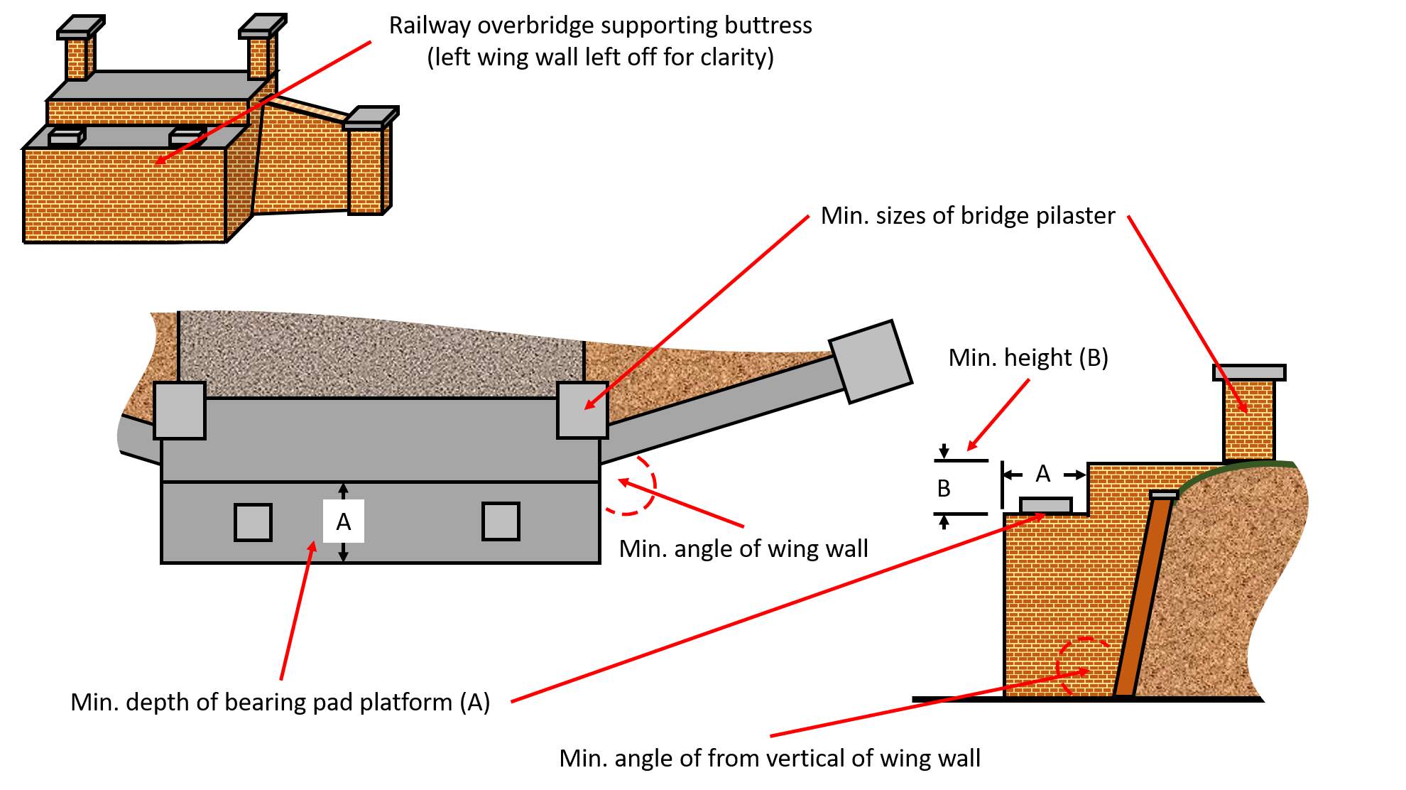
I’m trying to find details of the supporting Buttress and Wing walls (not sure of the exact terminology, but have provided a rough sketch below (Buttress 01) showing the information I’m trying to find.
Use Google maps and the streetviews. Look for railroads on the map, zoom in and look for roads passing under the railroad and then go to street view and check if there was something useful.
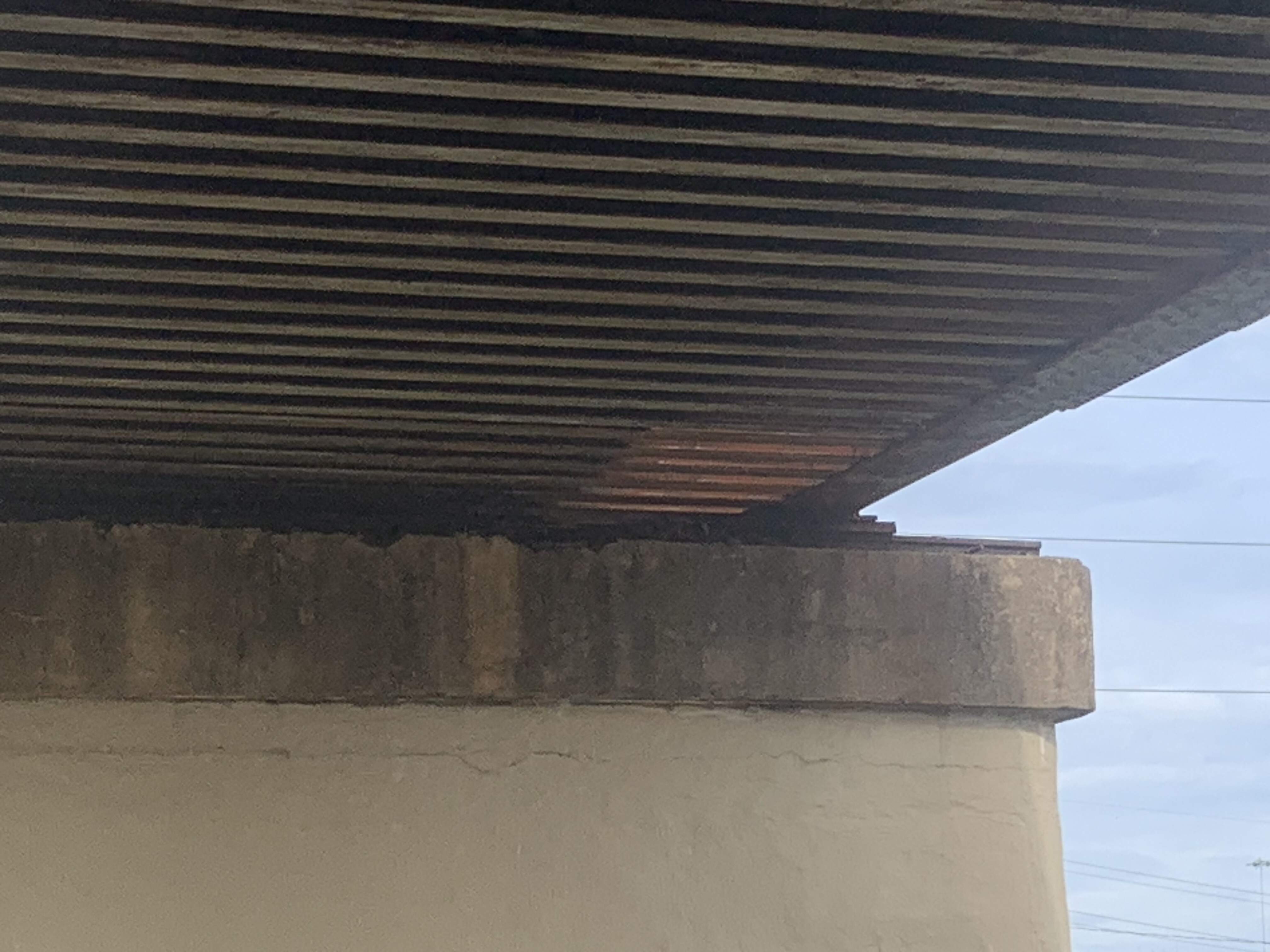
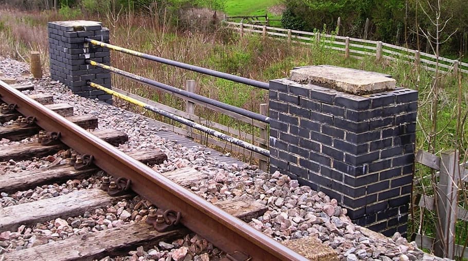
The capping stone (or concrete??) on this one seems to be at least the length of three bricks wide. Trafalgar Road, Hove
The buttress could follow the angle of the road but it might also be angled to suit some other needs.
Speaking as a civil engr. w/45+ yrs of experience, and I am not always right, the minimum angle of wing wall = 0. Totally dependent on the surrounding topography. The A & B dimensions are again dependent on the size of the structure, and yes a through girder is a good choice. I would say that a 4" - 6" thick bearing pad is adequate and it should be a couple of inches larger then the dimensions of the bridge shoe. The B dimension again depends on the size of the structure such that the top of the floor girders are level w/the top of the abutment. The ties then are laid on the floor girders and across the top of the abutment. The A dimension then is the size of your grout/bearing pad plus 4"-6" of clearance around it. None of this is exact but these dimensions should give you a good representation. As for the bridge pilasters, they are not found on most American RR structures and I see them as more decorative then functional so size them for esthetics.
Great to see you back here G… And I like the sound of this project… Lots of potential looking at the floorplan you have shown in it’s draft form…
Any other teasing info ??? Figures ? Vehicles ? I’m taking a wild stab at maybe some form of train type equipment ??
Just noticed the minimum vertical slope detail. Anything I have ever built the wing walls were vertical and not laid back. Typically anything laid back on a slope was slope protection for erosion purposes. The actual bridge footing was probably a spread footing at some elevation above the bottom of the slope. It might or might not have pile supports depending on the soil conditions. These however were highway bridges w/significantly lighter loading then a RR structure. Having said this, wall faces may be built w/a batter but this is a relatively minor slope back. I don’t think the brick walls of the time frame you are considering would have this feature. These are gravity walls dependent upon the dead weight of the wall to keep them in place. Thus they are built vertical. I wish I could draw you a force diagram.
In the plan you have laid out the RR engineers would generally have built the bridge abutment parallel to the roadway w/the bridge built on the skew. Your wing wall would connect to the abutment at the back or front of your “A” dimension w/horizontal angle and the slope of the top of the wall determined by the topography. Building a skewed structure from an engineering and modeling standpoint is not really difficult and definitely adds interest to your scene.
Again, hope this long winded diatribe helps and there are always exceptions to the rule.
A vertical wall needs to be heavier/thicker than a sloping wall and have larger foundations to avoid being toppled, unless it has a corner. Will also depend a lot on the type of soil behind the wall.
If the sloping wall slopes a lot it will eventuelly become a pavement (erosion protection
as explained by Buckeye above).
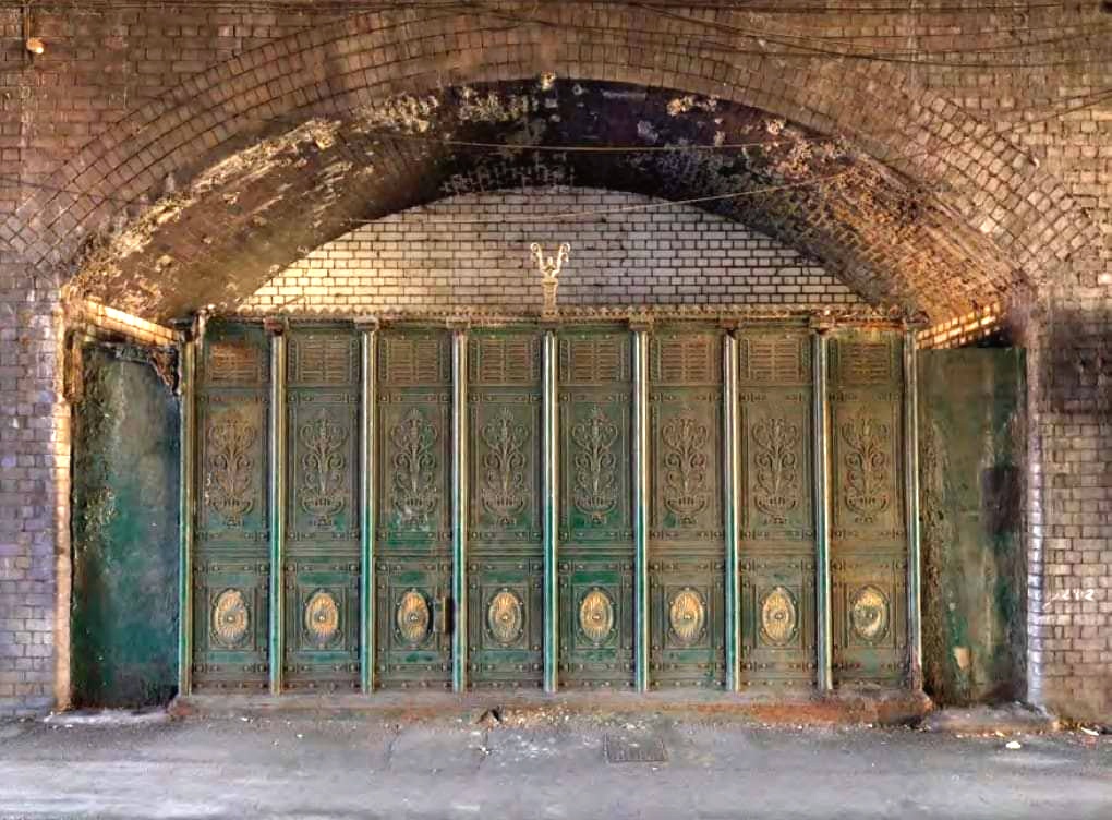
Firstly, it’s great to see you back. Secondly, it could be a backdate of the “Coronation Street” TV Set! It’s worth noting in Victorian urban areas the railway is often not carried on an embankment (to minimise the footprint in areas where land values are high) but on arched brick structures, these can be blind arches with infill or (like the “Corrie” set) open but closed off as business premises, thus:
I know you will be making your own, it’s just for illustration but it has some useful dimensions. Being lazy I acquired this for my never-started First Railway Group Build diorama (as usual it’s the wrong thumbnail but the link works):
The brick infills are two sided so you can have four blank arches, four enclosed, or any mix. I also contemplated these:
Eliminating the embankment will give you a bit more space on your base. In addition to the types I mentioned above there are Blind Arches with a set-back rear wall which have found various uses:
Ah the choices of engineering economics. My vote is for the original concept w/an embankment which provides space for vegetation. Aesthetically much more pleasing in my opinion. If you want to use the very space constraining structures I really enjoy the gritty heavily industrialized r/w.
G-man69 specified U.K., WW2 era, urban with some Victorian elements. Basically, in WW2 much of the structures in U.K. cities and major towns were still for the most part Victorian and not much improved, i.e. outside toilets (sometimes earth closets) and tin baths in front of the living room fire. The place I lived in for my first four years was on the first and second floors over my Great Uncle’s small shop which had been equipped with indoor sanitation (my first school didn’t, though) but we were still stuck with the tin bath. Fortunately for my parents both sets of their parents had been re-housed to new builds in the 1920s which had all mod cons. Luftwaffe urban clearances were widespread throughout the country, not just in the south, and did a lot to change the nature of British urban areas (In Portsmouth and Southampton when I was in that neck of the woods in the 1970s there were still a lot of bomb sites being redeveloped and quite a few that hadn’t been touched). A lot of nice old buildings went in the 1960s when “Urban Redevelopment” did for a lot the Luftwaffe missed. Basically what I’m saying is that what is wanted is Victorian (or earlier) “As built” but soot-caked from decades of coal fires. In working class areas aesthetics were for the most part within churchyard walls…
Railways, when they came along, tended to blast through existing (urban) landscapes^ or new builds were crammed up against them, in either case the footprint was as narrow as possible. There was an added bonus as the railway companies could rent out the space under the arches, maybe for a pittance but it all adds up. I’m not saying partial or even full embankments didn’t exist in urban areas, it’s just that I’m not familiar with them.
^Near where I grew up in a semi-rural area a railway embankment went over over a graveyard, they just removed the headstones and laid them on the slopes of the embankment. The railway is long gone but as far as I know the embankment (and, I believe, the headstones) is still there.
Hey G welcome back to the brotherhood of paint sniffers and finger gluers ( or is it the other way around? )! I sincerely hope your mojo gets back soon!
I have little to say about the subway, other than that I will follow your progress, as always…
Thanks, Always helps to understand the context. Different timing and development patterns. Generally speaking railroads in the US had more space to work with, even in the urban environment.
I had the joys of bathing in that tin tub in the kitchen and winter trips to the outhouse but it was at my grandparents rural farmhouse. They finally had indoor plumbing and central heating installed in the early 60’s.
In the 60’s my father’s office assistant was a British war bride. Bill and Elsie went to our church. Bill worked in the Ford Engine Plant on the west side of town, Elsie worked for Pop and they raised 6 kids. I remember that when each one of the kids graduated from HS they spent the summer with Elsie’s family in Birmingham. I thought that was pretty cool. My dad told me it was so the kids would understand how good they had it here in the US. That was a trip that probably would have done me some good as well. Never have made it off of the N. American continent. Never felt I could afford either the time or the $'s.
I can’t blame you, it’s big place with plenty to see. I’ve never left the U.K., it’s a small place with plenty to see… As far as I know, my mother, her sister and both grandmothers never went overseas either. It’s a different story for the menfolk of the family, but they had free travel because of the activities Kaiser Bill, Herr Hitler and the rest of that crew…
Of late I have been revisiting places, and walking routes, with which I was familiar in my youth; but only virtually, courtesy of Google Maps, and Street View. It gives new meaning to “Travelling the World from your Armchair”.
Yah, my dad and his next older brother got those trips. Pop was a forward observer w/a Long Tom battalion and Uncle Rich was a LT. in the 101st Airborne. Neither one of them talked much about things except to say they were not interested in going back. I do know that my old man was part of a unit that helped clear out one of the concentration camps when things were over.