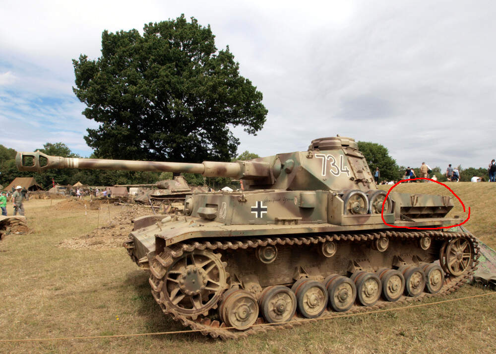
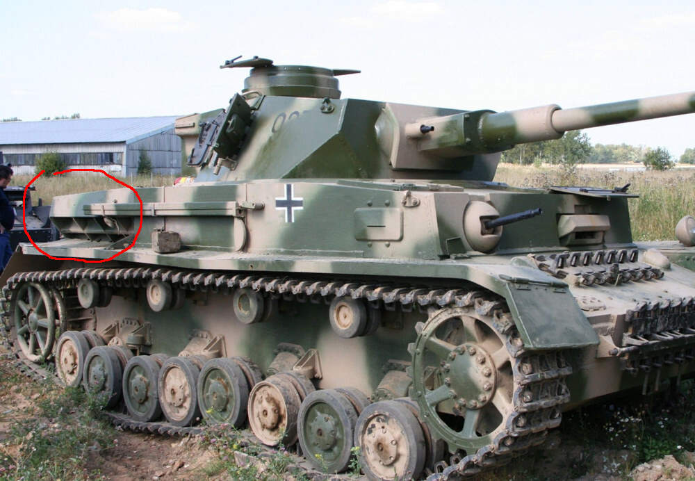
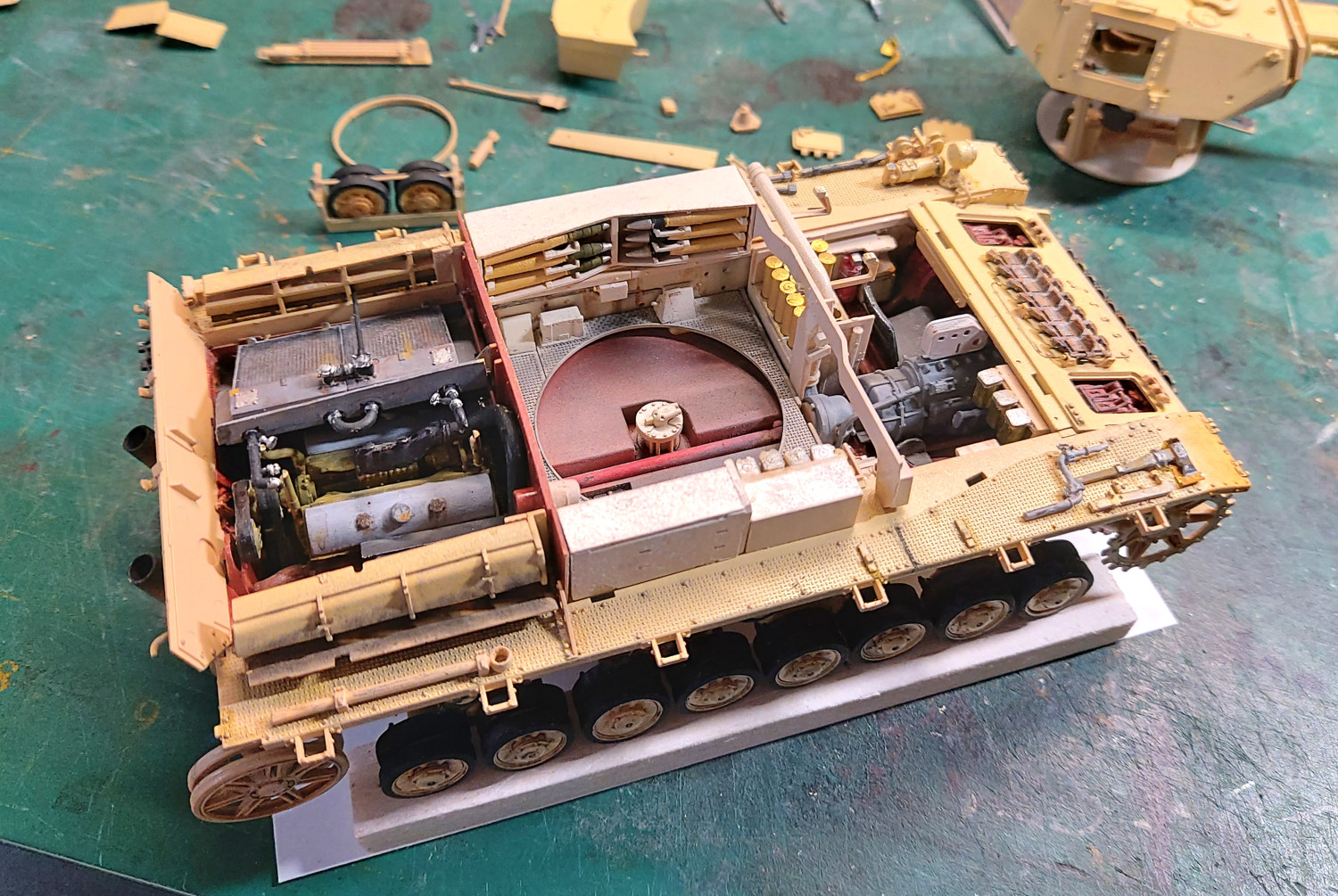
Now I need a bit of info. I have the air vents/intakes on both sides. Half the images I see on the web have open vents. Others have them closed up. Can someone tell me if these are an open or closed option depending on conditions or did some iv J’s have these cover no existing. RFM give PE covers that cover up the detail. So I would like to have one side open. Or is that a no no?
I think the idea was that they protected the radiators when in action. Or alternatively they could be opened when it was hot and closed when cold. They were always fitted AFAIK. Some of the older Tamiya PzIV kits had them moulded open with the flaps moulded onto the mudguards.
They are entirely intended to adjust the cooling air flow to help the engine operate at its best temperature. They are simple sheet metal components and have almost no ballistic protective value. The intake grates themselves are constructed from armor plate.
Well I feel a little sheepish. I never knew what those flat molded on squares were on the fenders now I know. This would be a perfect PE part. Tells you how many of the current PZKFW 4 kits I have done.
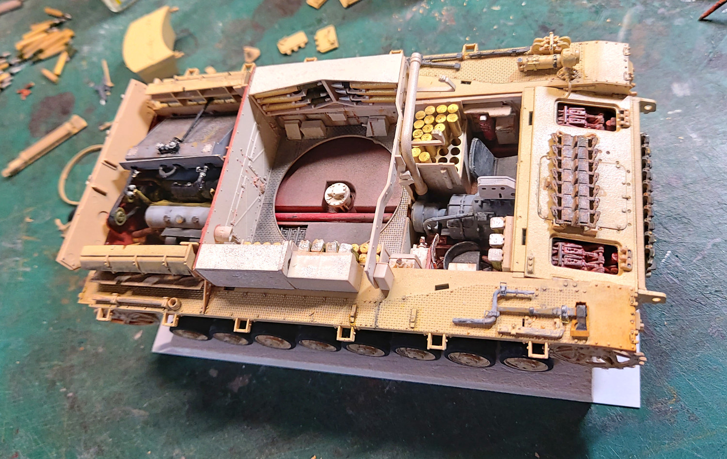
OK an update. I put the PE on one side. I bent it in a few places to make it look the part. The other side I used the other option with the plastic cover. But I left it partly open.
Now after all that i read ahead and found one more piece covers the work all up. Darn. At least I know it’s there.
The top is just dry fitted hence a few gaps.
There are, I believe, a series of separate flaps, to allow for some control over the airflow.
They clip on at the top when closed and are held down with half butterfly nuts when open. Not sure that there is a way for them to be half-open unless propped or otherwise held that way with an object. Did they have bodge tape in the Wehrmacht🤔
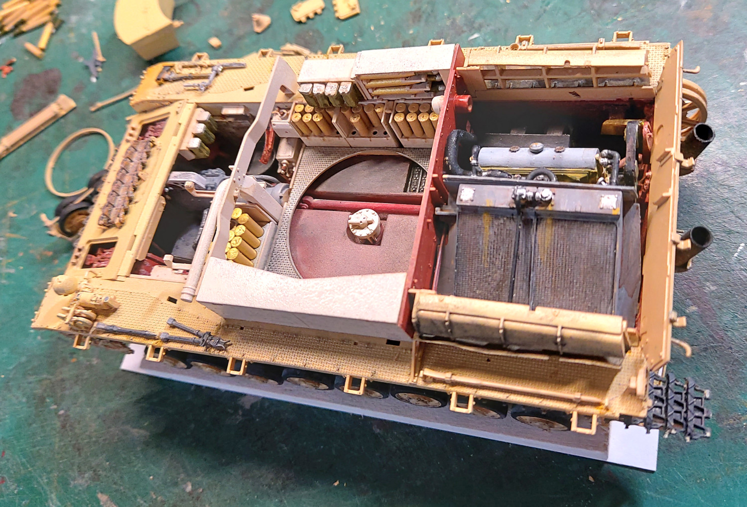
I’ve come the conclusion that the ‘best’ way to replicate the real thing is to cut the PE part into the 4 sections.
Most of it will be covered when the top cover goes on.
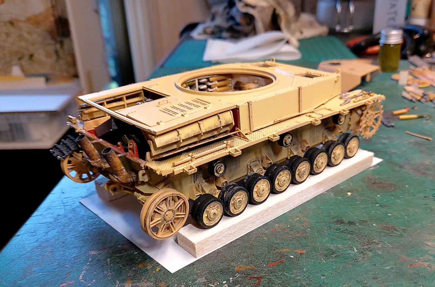
OK a while since I’ve done much. (Travel and illness).
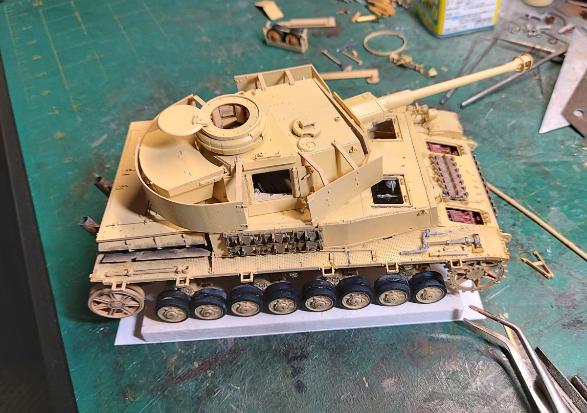
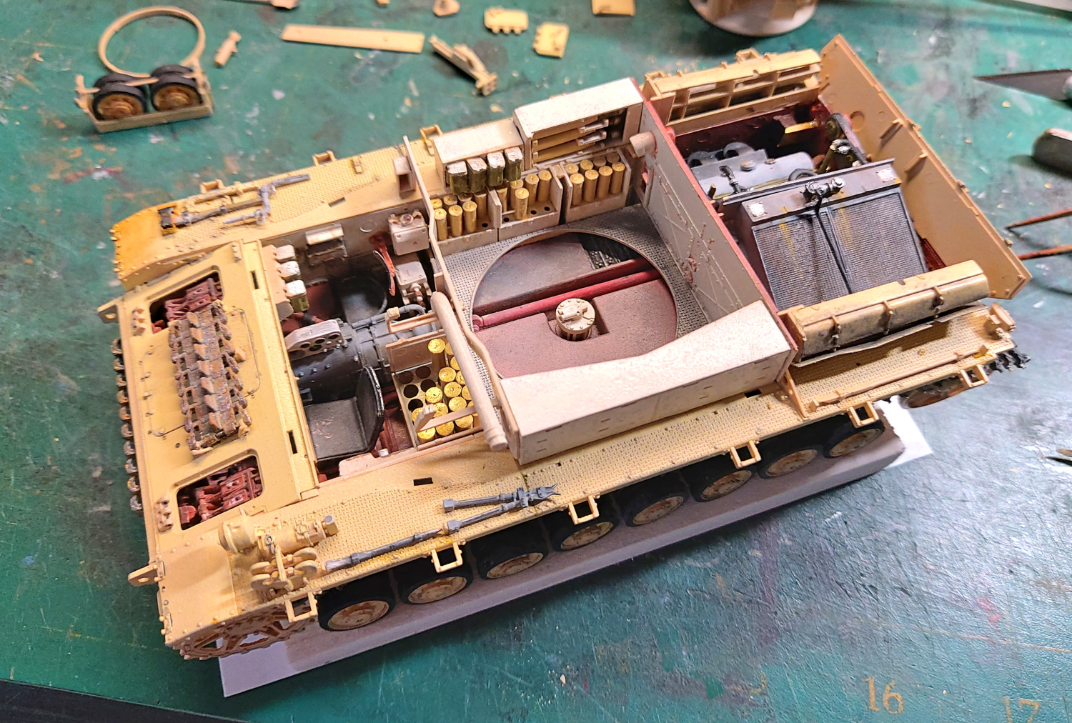
I’m now at the stage of fixing the hull top on. Sad day actually because most of the interior detail will nolonger be seen. I guess that’s the down side of interior kits. (I’ve 2 more interior kits in the stash).
I’ve tried to make the hull top removable. But that has some issues. So next time, maybe! Turret is done and just waiting to be dropped in. I’m fighting with the RFM tracks. Every time I look at them they break. So bit by bit I’m going to glue them in place.
The model looks very nice. The interior iswell done and looks great!
Regarding the engine cooling flaps. Tamiya makes a small set of PE with the flaps already separated. Every other flap can be positioned opened or closed etc as desired.
I don’t think it was normally possible to position the flaps half way open or closed.
Have you considered using small magnets to hold the upper and lower hulls together? I found plenty of small but fairly powerful magnets on ebay for such tasks.
The problem with not gluing down the upper hull is that there is a small, very small, twist somewhere. Yes I’m a bit pedantic but if I leave the upper hull unglued I will always be aware of the small gap on one side. I’ve done a bit of sanding here and there and improved it but the last 0.5 of a mm is bugging me,
Before I glue it down I’m considering installing a couple of clear LEDs inside. Wires out through the bottom. That may give a better view of the insides.
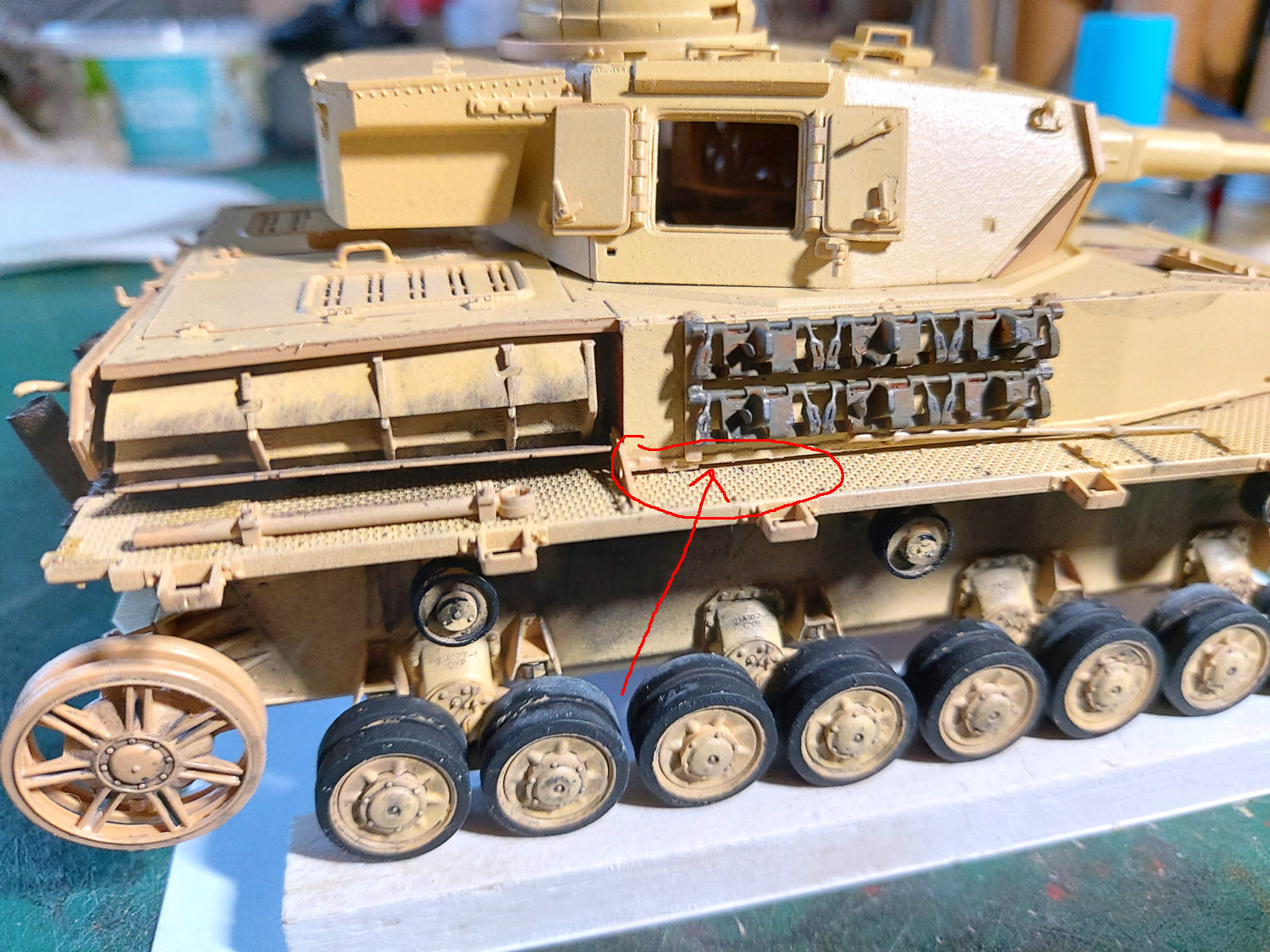
A shim may work. Below is an image with a red arrow showing the gap. NOTE. The gap is bigger in this photo because the upper hull pops up due to the tight fit. If I was to glue it down this gap would be about 0.5mm.
Yes It could be hidden with tools, mud etc. But it just annoys me that that gap is out smarting me. Note - the turret etc are just dry fitted!
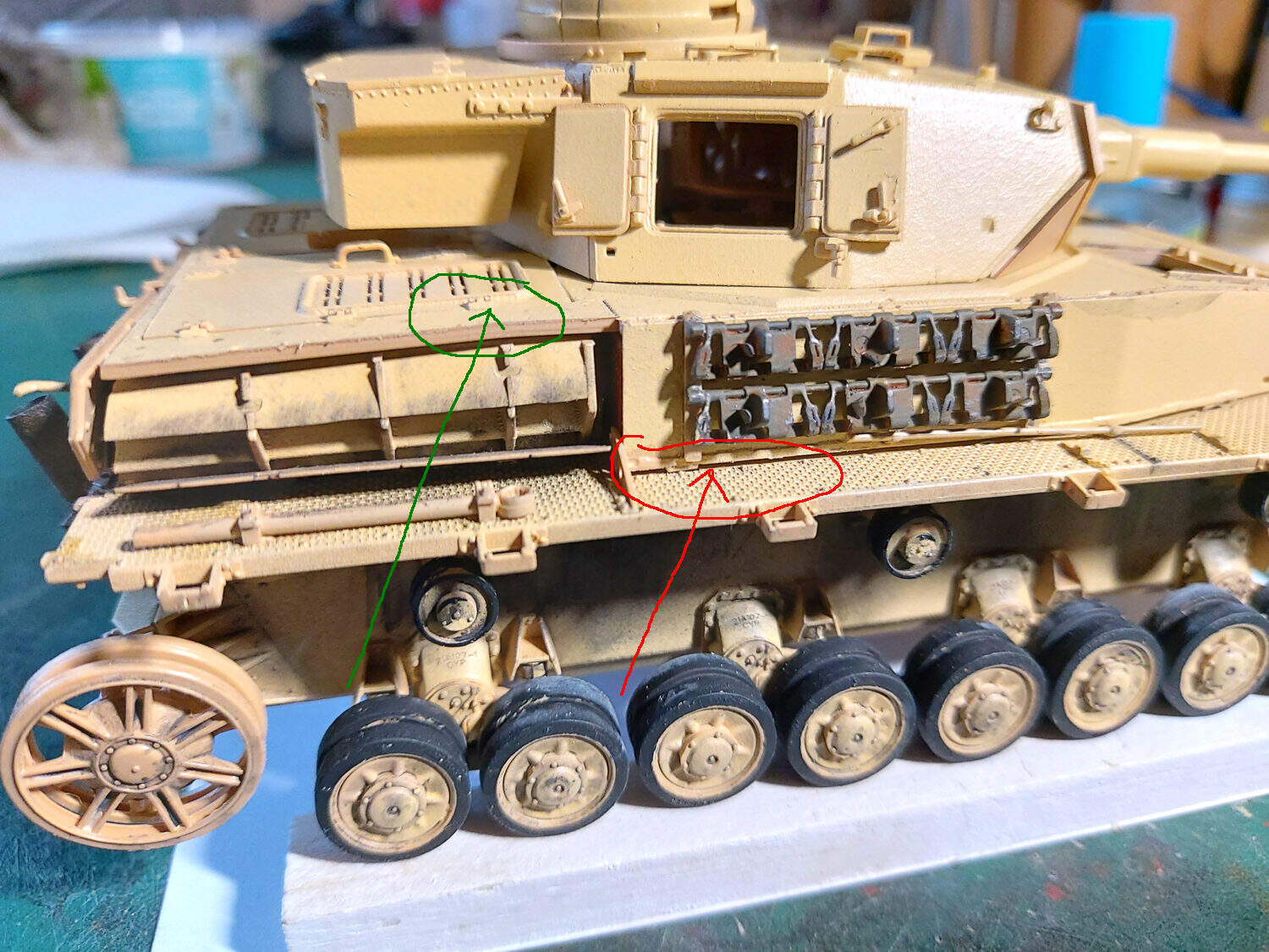
OK an update. After awhile the light bulb went on!!
I decided I had sanded/trimmed enough off the hull and was about to give up. Then the light bulb moment. I decided to look under the hull top. And there staring at me was the problem. There is a molded ridge around under the engine hatch opening. (See green arrow). I removed a section of the ridge and bingo. Fitted just fine. As an aside - the very same hatch opening is a fraction to small for the hatch cover. To fit the hatch cover you need to remove a small amount from the non hing side.


 and looks great!