I have a question about the lifting hooks on an M47 Patton. (And yes, the M47 is stretching the definition of modern, but hey…) I asked this question on another site as well, but was recommended asking it here.
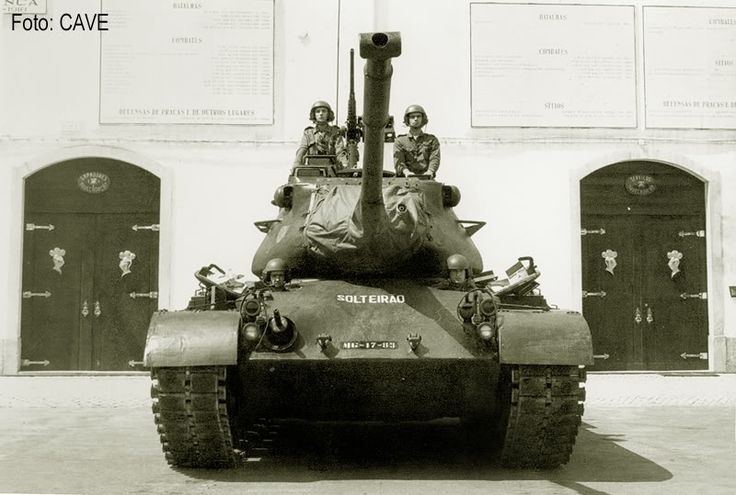
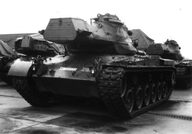
I’m currently building a Portuguese M47. The vehicle can be seen on the included picture.
From what I understand M47’s came with two possible types of lifting hooks on the glacis; rounded and flat. Looking at the picture they look round to me, but it’s hard to be certain. Does anybody here have any knowledge on the subject? I’m aware that M47 lifting hooks is very niche indeed, but I was told people like @Frenchy have a lot of knowledge on the likes of the M47.
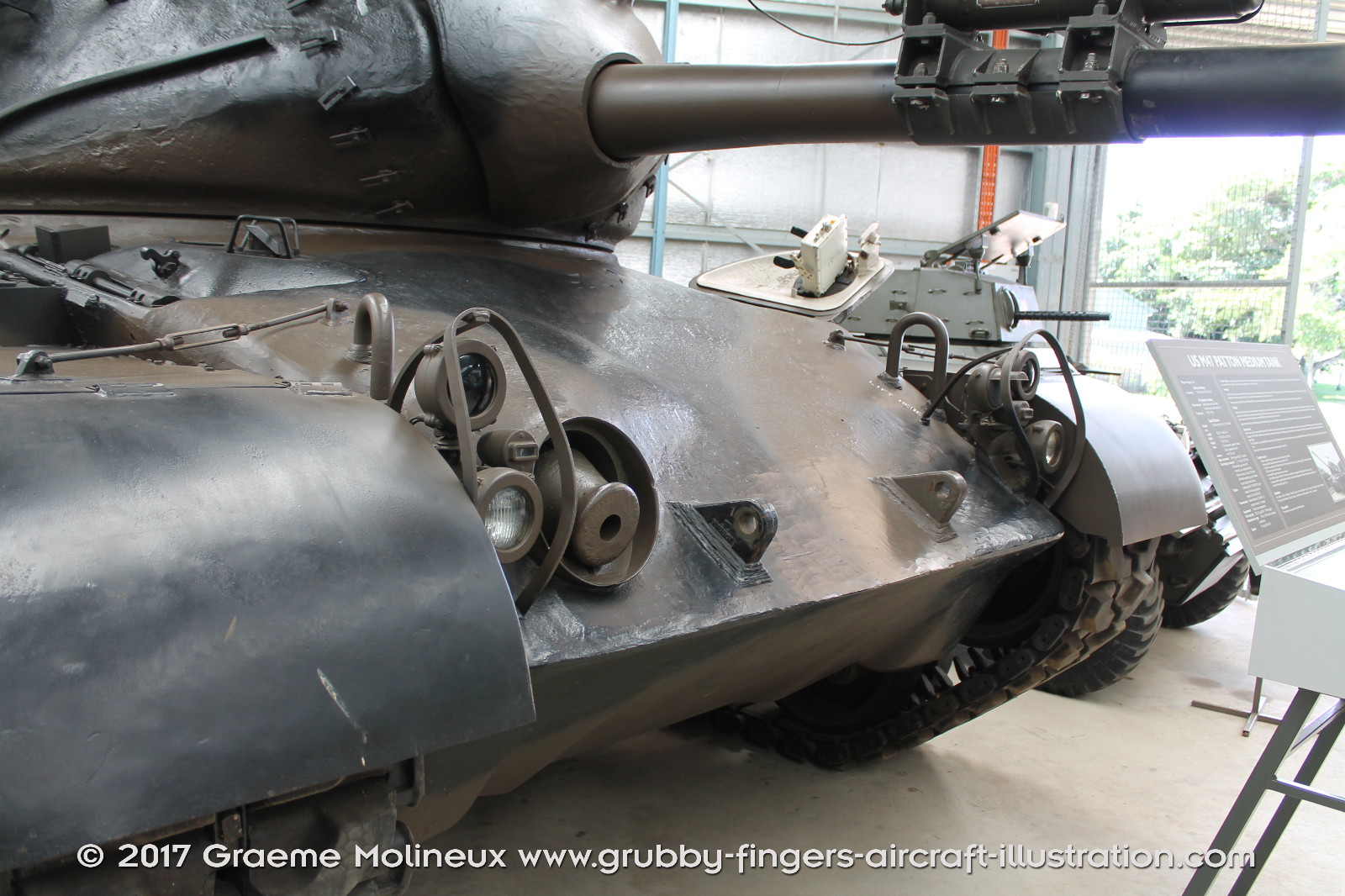
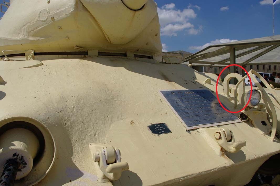
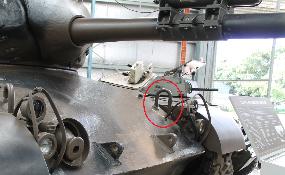
I believe he is talking about the lift rings further up the glacis plate behind the lights. Based on the below pics, they were both square stock and round stock. I am guessing it was based on either different production runs or different manufacturers/plants making the hulls. Either appears correct though.
Correct. Unfortunately, there is virtually no info on who built which tanks, so sorting out which features (e.g. turret subcontractor, hull construction) go with which manufacturing plants so a matrix of features like with Shermans isn’t possible.
My evil streak starts thinking about building a model with those hoops made from hexagonal material and try to convince viewers that this was the third possible variation, built in very small numbers.
I did a quick Google image search for Portuguese M47s and found maybe a half-dozen pics that looked to have the square-section loops, and a couple with round ones, so I think you have a choice.
I did a bit of digging for a Takom M47G review a while back. Production was at either the Detroit Tank Arsenal or American Locomotive Company (Alco).
There are some differences that I’ve noticed beyond the lifting hooks but I’ve never found a correlation beyond the turret. This is what I see for the turret.
Config 1 – sledge hammer mounted with head at turret middle and bore brush staff section loops only on turret right side
Config 2 – sledge hammer mounted with head at turret rear and bore brush staff section loops only on left side of turret.
The mount for the sledgehammer head is a fairly simple loop as seen in these picture.
In essence, some foundries cast the the lower portion close to the final re-entrant shape using a more complex mold while others used a simpler mold that left the base oversize but also required additional machining. Those types have what amounts to a conical relief cut into the base. The turret is irregularly shaped above the base so the margin of the conical cut is likewise irregular, and disappears altogether forward of the bustle where the sides tuck in below the projected surface of the cone. One foundry also made a cylindrical cut above the bottom to clean up the widest portion of the base to get within the maximum envelope diameter.
Thank you all for your help. I’ll go for the rounded hooks and if that turns out to be incorrect in the furure, I’ll sit silently in the corner and sob.