Rigging Basics. If everyone is happy to start the topic here then I am happy to try it. I think it should be a WW1 aircraft if it is here but the ones I have are not suitable for a rigging ‘mule’.I need something I can just do a basic build on and the only ones I have that I can do that are the Stearman and the Moth, both too late in period. I’ll see what the LHS has tomorrow.
3 Likes
Andrew,
I think this is a wonderful topic, and appropiately timed. I’m currently deciding on what subject to do for the Great War campaign, and started out picking the one with the least amount of rigging. So, did a lot of research and have come up with two methods that I’m going to do a proof of concept, and planned to put together a how to. I just finished cutting the piano wire for the Stearman and am planning to do Eduards EII and/or SE.5a. The Stearman with cut wires, and the other ones using a slightly modified method I gleaned from fellow modeler Plasmo, that uses EZ-Line and homemade turnbuckles. Both appear to be straight forward, and relatively easy. I believe the big trick is overcoming the fear of rigging.
John
1 Like
Went to the LHS today and they had nothing suitable for this job so I think I will use the Moth. I did however still spend my hard earned cash and treated myself.
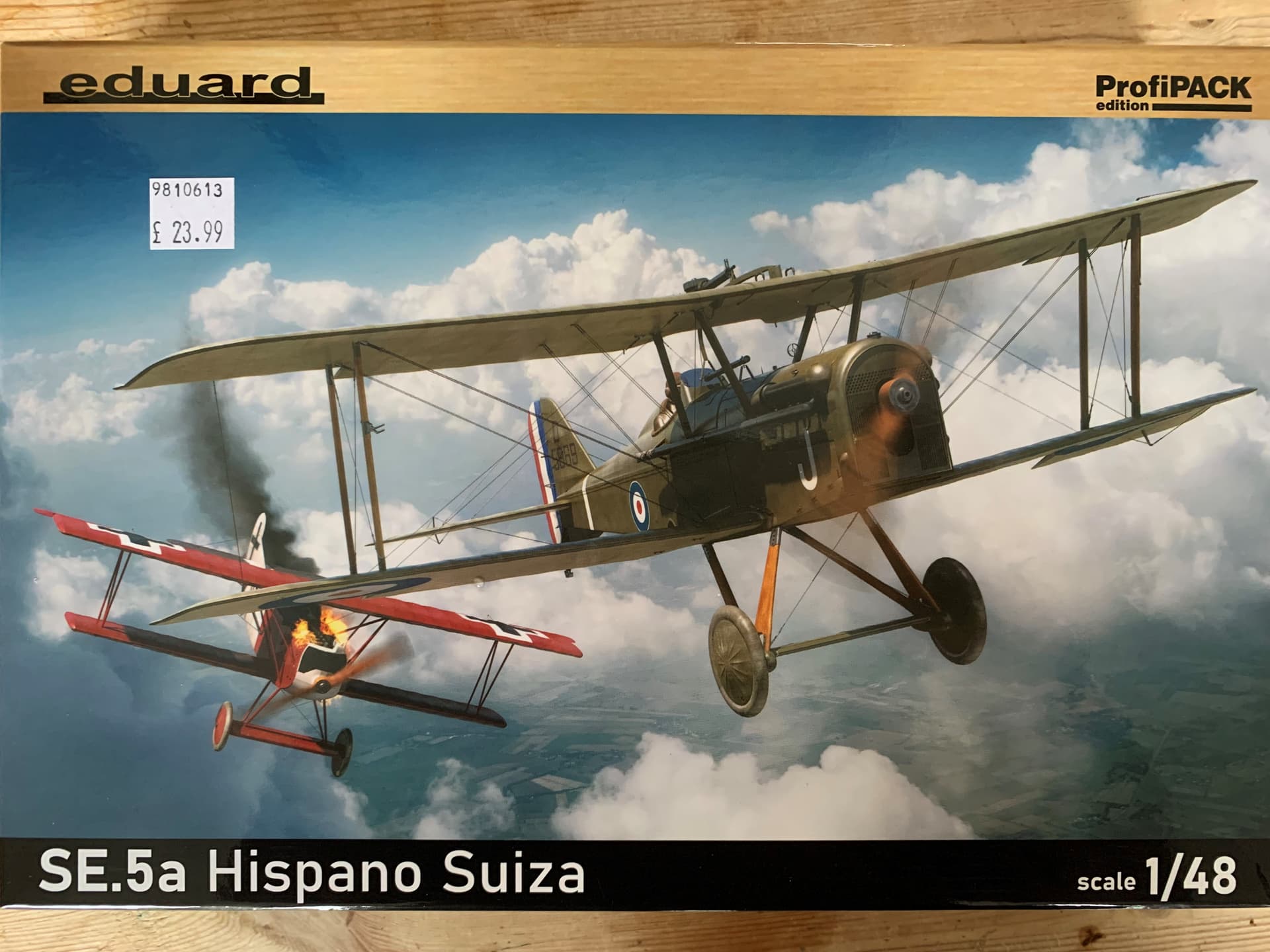
If I use this one it will be weeks before I get to the rigging!
The method I will show is the easiest one I know and will work using EZ-Line or straight monofilament fishing line. You can add detail like brackets and turnbuckles but the basic method stays the same. Tools. Small snips, scalpel, Magnifier, fine tweezers, Dremel type drill and fine bits, I mainly use 0.6mm, cocktail sticks, a wooden clothes peg. Normally, I use cyano adhesive, this gives good strong results but setting time can be unpredictable. I tried using 3D printer resin on the O/400 and this works well to tack wires in place but doesn’t have as much grip as cyano. I have got some UV sensitive adhesive on order, that might be better.
Why fishing line? Very fine, reasonably strong, limited stretch, cheap, damage resistant, actually strengthens the model.
Why EZ-line, fine, forgiving, stretchy so tends not to sag. Why don’t I use it? I’m a cheap skate, damaged models tend to stay in one piece and when re-assembled the rigging continues to hold the whole thing together and finally, I have never had any major problems with fishing line
2 Likes
Looking forward to this.
And that SE5 looks nice.
I said last time I was in that I was looking for one, they offered to get me one but I turned it down. They got it this time so I had to have it!
Rigging.
While you are doing the first steps of the kit, start looking at the rigging plan or photos. You need to understand how it works, it isn’t there just to confuse modellers. Aircraft are very light structures but need to withstand great forces. Wood is a good material for resisting bending and compression forces, but poor in tension. Steel is heavy but good in tension. A biplane uses steel wire to resist tension forces in the wing truss. These forces are different in flight to those on the ground. In flight the wings are lifting up but the fuselage is trying to fall, wire that connect the bottom of the fuselage to the top wing are lift wires. The RFC and RAF from early days doubled these wires for safety. Wires that go from the top wing centre section to the bottom wing are landing wires, they stop the wings collapsing on the ground.
Running through the wing are the spars, wooden beams inside the wing that give it strength. The wires are usually attached to the spars using small steel brackets. The interplane struts run between top and bottom wing spars and work in compression, holding the wings apart, they too are attached directly to the wing spars. The pic is a Currie Wot home built aircraft but is the same wire layout.
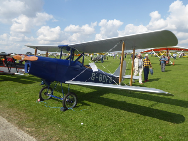
Lift wires run from bottom of fuselage to underside of top wing just inboard of the struts. They are doubled. One pair for the front spar, one for the rear.
Landing wires run from the inner end of the upper wing spars next to the cabane struts (the ones between the fuselage and the upper wing) to the lower wing spars next to the interplane struts. These are not doubled. Bracing wires run between the interplane struts but attach to the spars with small steel brackets.
The wire can be multi strand with eyes swaged onto the end or streamlined wire (as here), made to length. Adjustment is via turnbuckles that can be seen on the lower ends of the wires.
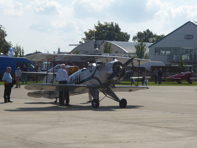
This pic is a Bucker Jungmann. Here the lift wires are single rather than doubled, you can see they join the wing inboard of the interplane struts and the wires are probably multi strand.
3 Likes
Thanks for this tutorial. I have long wanted to build WW1 aircraft but my efforts at rigging them were not happy. Getting over the fear of rigging is indeed the first step.
Somewhere in the stashes I have a Hobby Craft 1/32 Nieuport 17 kit that looks like a good place to start. I just have to find it . . .
Paul
1 Like
Nieuport 11/16/17 only have a single spar lower wing hence the V strut. This changes the rigging pattern slightly, makes them a bit easier
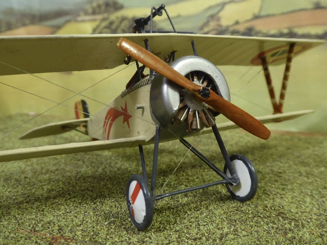
This is an 11 but not much different in rigging to a 17
You can use an elastic thread, there are many brands with different sizes for many scales, they are used on biplanes and ships rigging.
To measure the lenght of the rigs you can use a divider compass, the lenght must size a little short to stay tight. I use super glue CA to cement both ends.
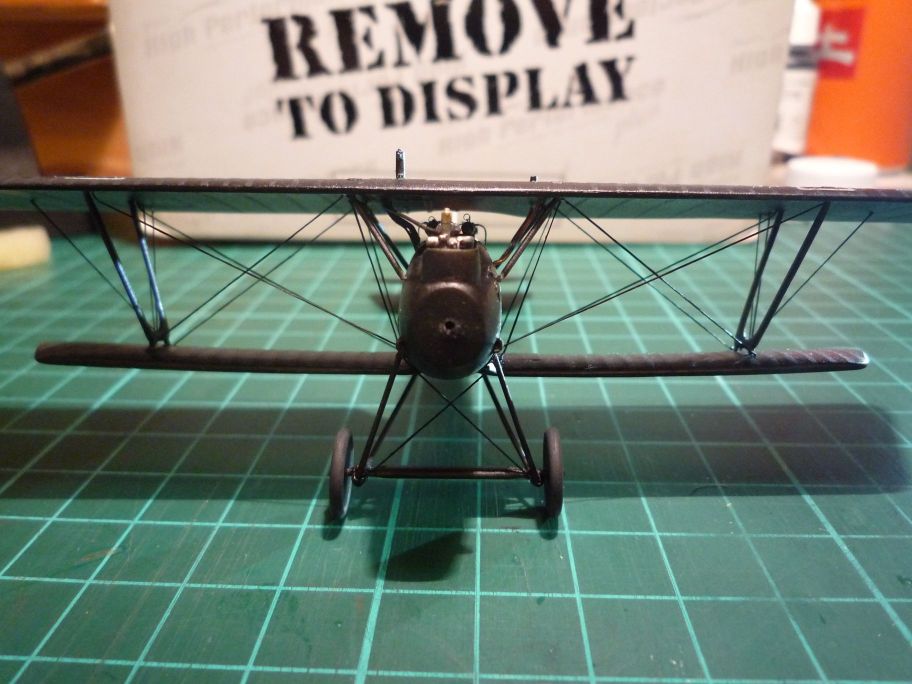
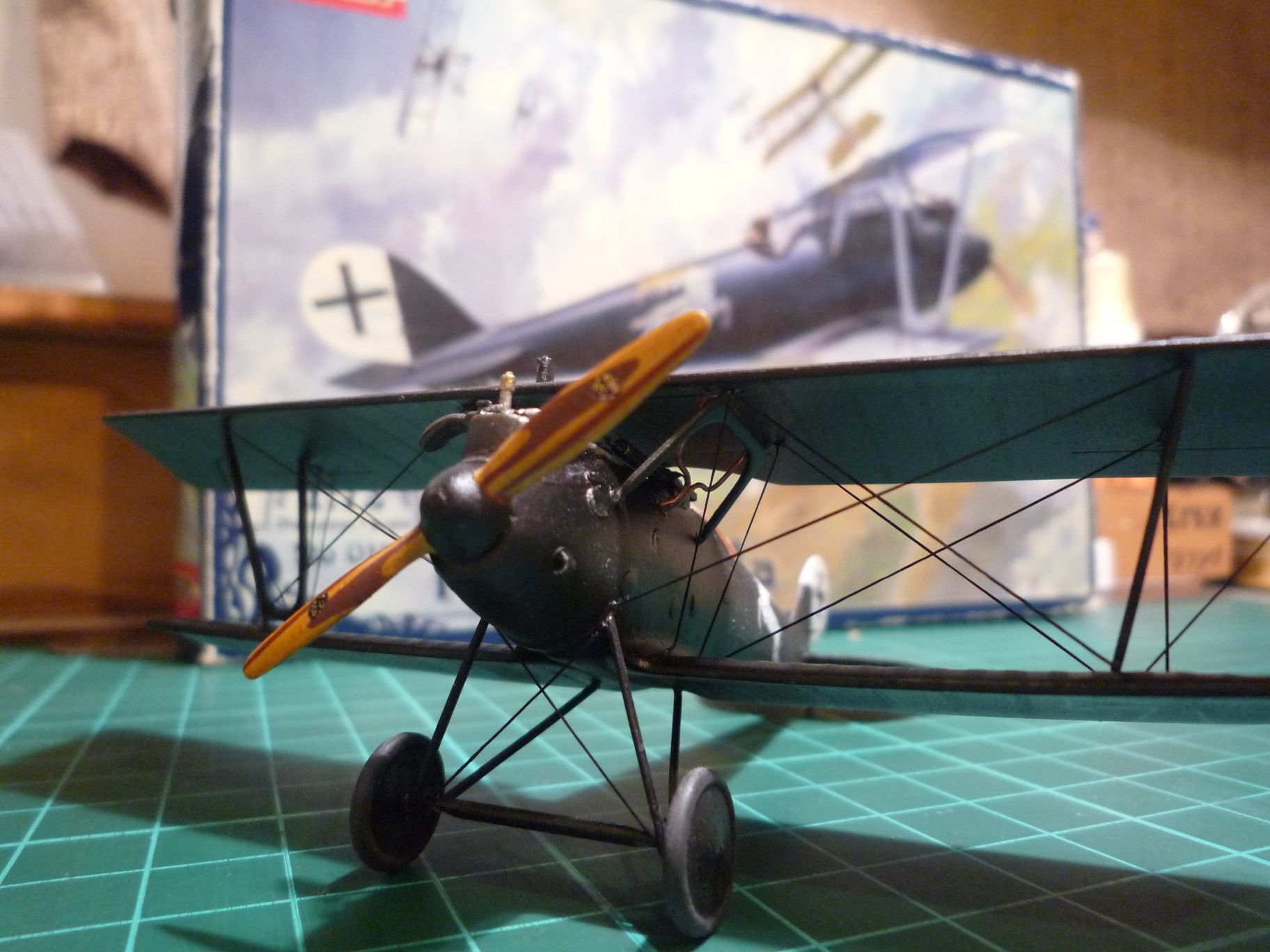
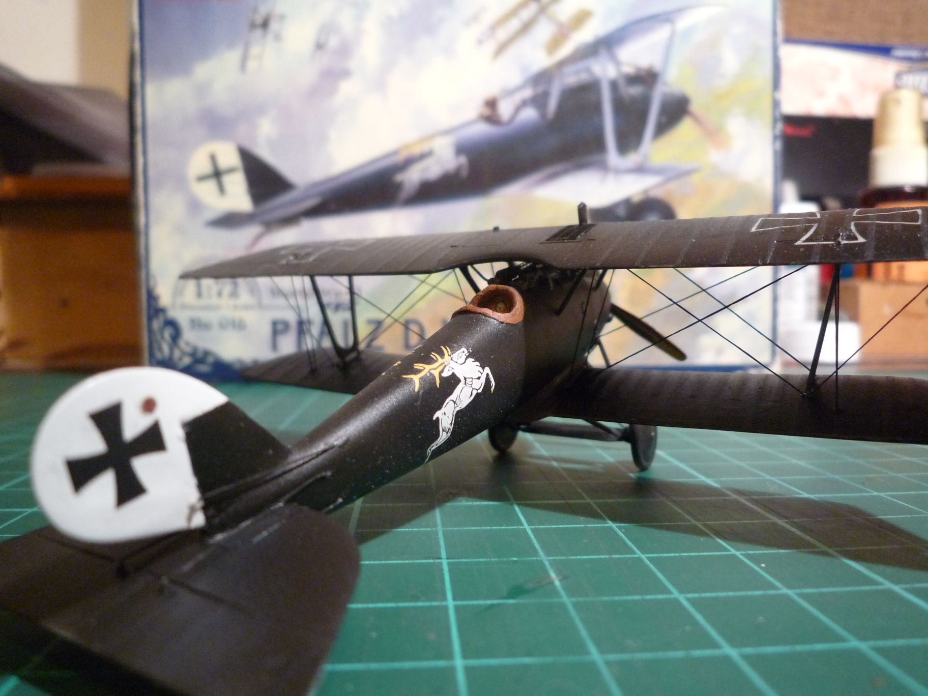
This is a Roden Pfalz in 1/72.
3 Likes
After extensive research and hours of midnight oil burning I finally uncovered some Tiger Moth photos for the rigging pattern

Meanwhile
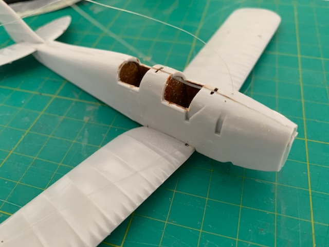
Made a start on the kit, it is about as bad as I expected, Locating pins are out, as are the windscreen locating slots
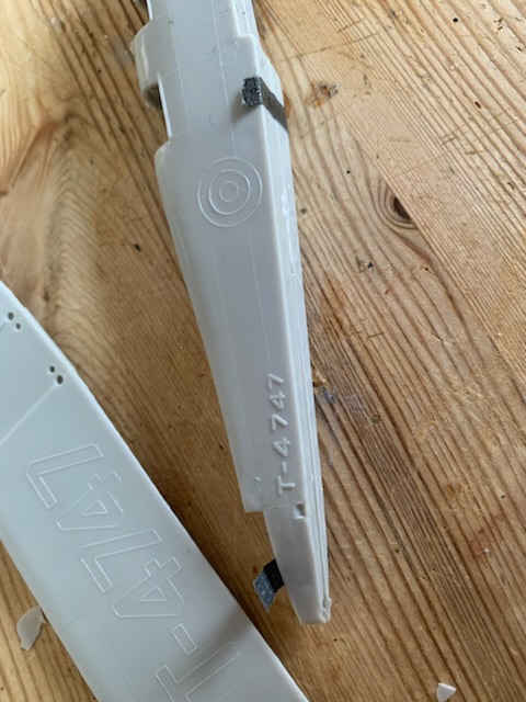
Decal positions are moulded on, and worse, they don’t match the decals

Pin marks, wing sections wrong, flash, thick risers, ah well here goes.
Enough whingeing about the kit, let’s start rigging.
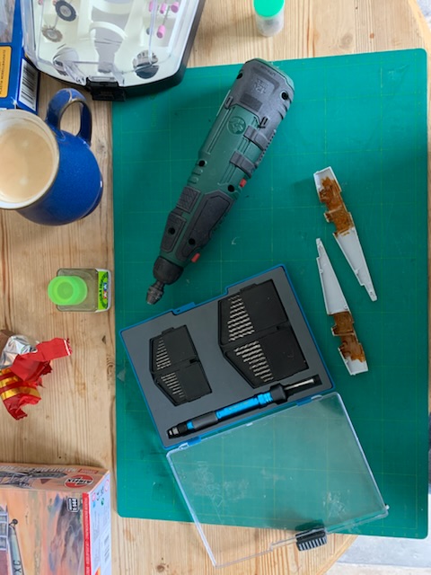
Drill, check, bits, check, coffee, check, biscuit, check.
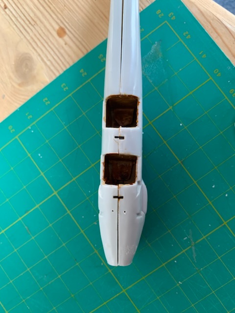
Interior of the fuselage complete, as far as this one goes. Drill is a Lidl special, cordless, variable speed from 5000rpm to 25000 rpm with a Dremel chuck fitted. Bits are from Aldi, two of each size from 0.6 to 2.5 plus holder.
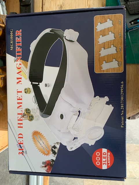
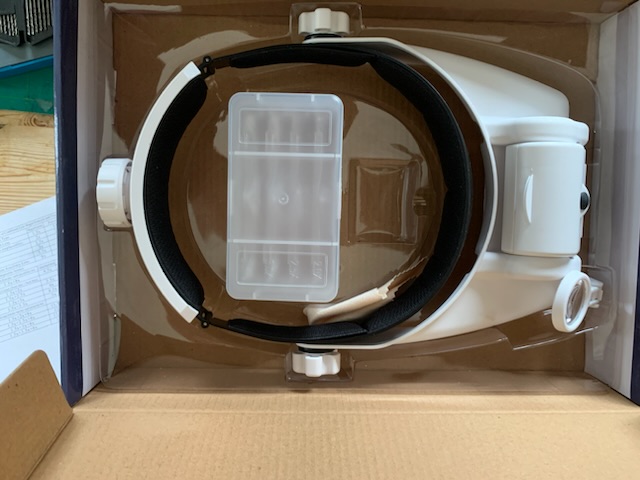
Some one asked about the magnifier, £24-ish from Amazon, very comfortable, lots of adjustments, only down side I have found is the loupe is fitted for the right eye only, suits me but won’t suit everybody
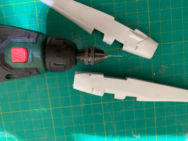
0.6mm drill fitted to chuck, fuselage holes drilled as per the picture
Two more drilled in front of the front windscreen. Drill the holes for rudder and elevator control cables now as well, while you have access.
While drilling keep the speed of the drill right down as slow as possible or the holes will come out oversize as the drill melts it’s way through.
2 Likes
Love to hear more about the measure and install to length process. All my rigging to date relies on a blind hole in the top wing, thru holes in the bottom wing and fuselage to pull the lines tight. ![]()
After a break to do other modelling stuff, back to rigging the Tiggie. I drill the wings before moving on, 0.6mm holes right through, most Great War aircraft have thin wings and at 1/48 or smaller blind holes are difficult.

Need to clean the rag off the outside before starting anything else.
Need holes inboard of the strut locations and between the struts. If this was the inner strut of a 2 bay biplane then another hole would be needed just outboard of the strut.

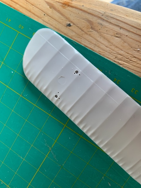
What happens when you set the drill speed too fast. This was 1 notch off the bottom speed for the back attachment points, correct speed for the front ones. The drill has melted the plastic
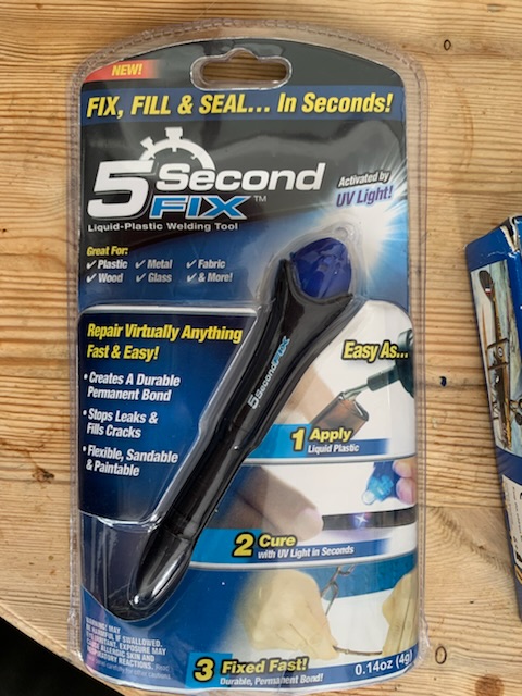
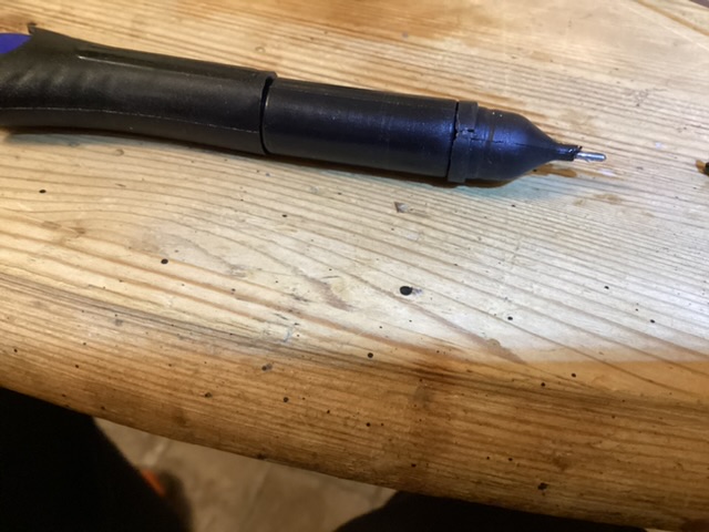
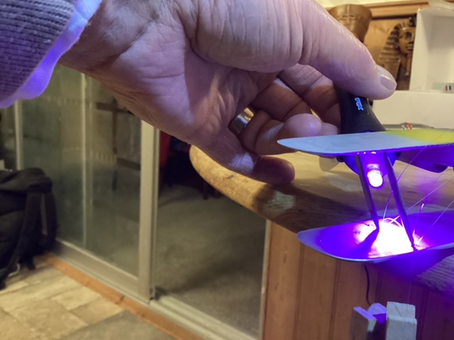
A word about adhesives, previously I used thin cyano, putting some on a plastic bag then picking it up on a cocktail stick. With the O/400 I tried using printer resin as a glue, you can apply it, set up the joint, then set it off with a uv-torch. Results were mixed, for tacking lines in place it was excellent, but I was brittle and broke easier. So I looked on EBay and found this stuff, £3.50 and includes a uv torch and a precision applicator. We shall see.
2 Likes
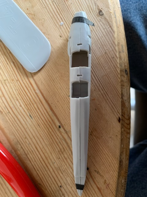
Before the fuselage is closed put a loop of line between each pair of holes, secure with a blob of cyano in one of the holes. I try to put the cyano in the hole with the line already threaded through,then pull a little line into the hole. Once all the line are in I join the fuselage.
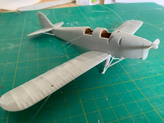
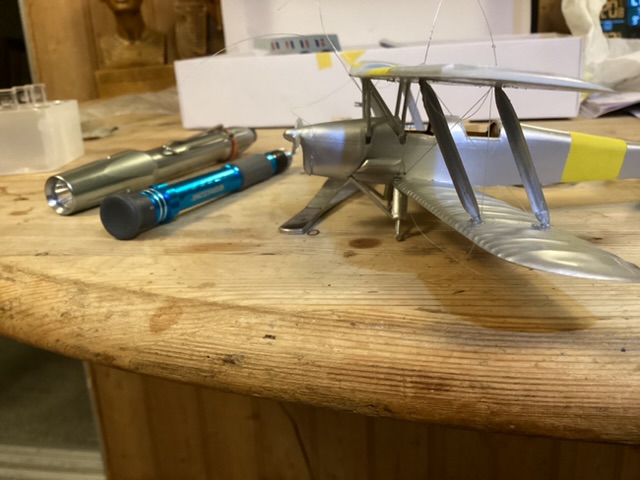
Build the fuselage and wing, in this case I added the undercarriage, usually I don’t. Trying to prepare for the next stage, painting.
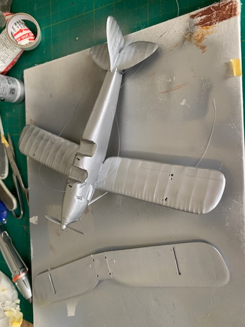
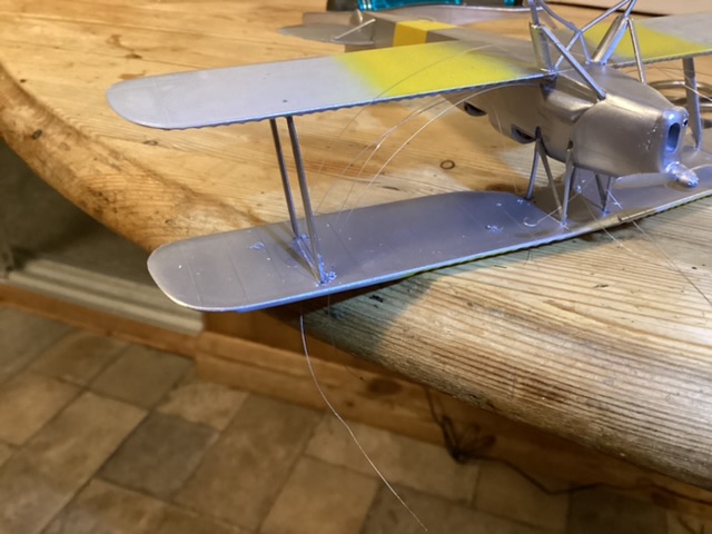
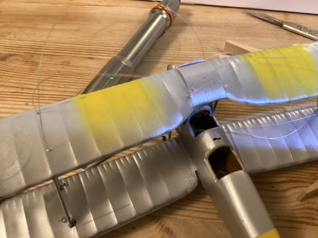
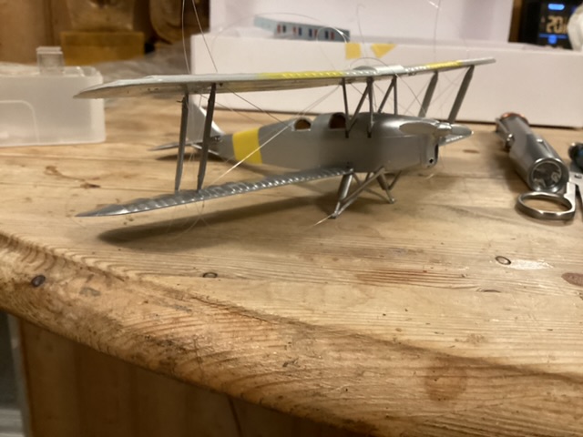
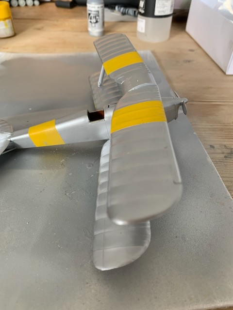
Mask and paint the fuselage, top of lower wing, bottom of top wing. Not doing the camo scheme in the kit, doing the pre-war silver and yellow, easier to mask
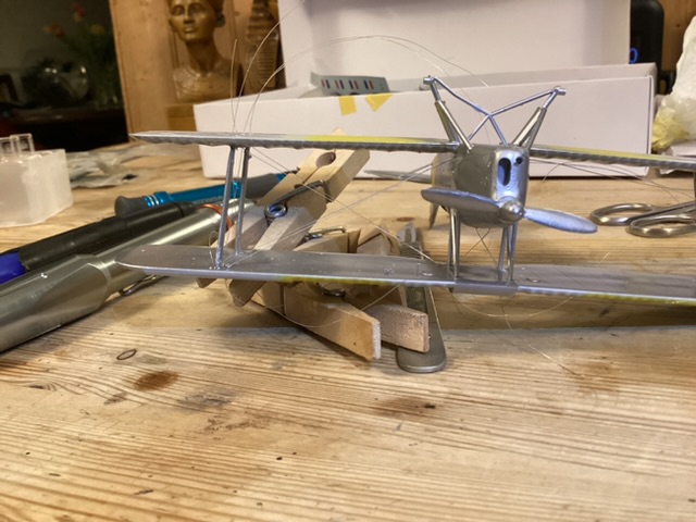
One of the features of this kit are the joined interplane struts. This makes assembly easier but they can’t be drilled for rigging. So I have trapped a loop of line under the strut assembly then glued it in place so I can use it as bracing wires

Now time to fit the top wing, Lined up nicely without needing a jig. Although I had painted the yellow panels, I haven’t done the silver yet, same under the bottom wing. Left it to set.
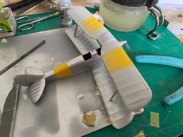
Yellow is Tamiya Flat Yellow, Silver is Vallejo Model Air thinned with water, no problems with clogging this time.
2 Likes
Will be interesting to see how that UV adhesive works. Have been looking at that one myself.
First job towards doing the actual rigging is clean the holes out using the drill I used to drill them and a bit holder. Most should be fairly clear but occasionally one gets blocked
Thread the lines through the holes, these are the flying wires, I do both front and back before glueing.
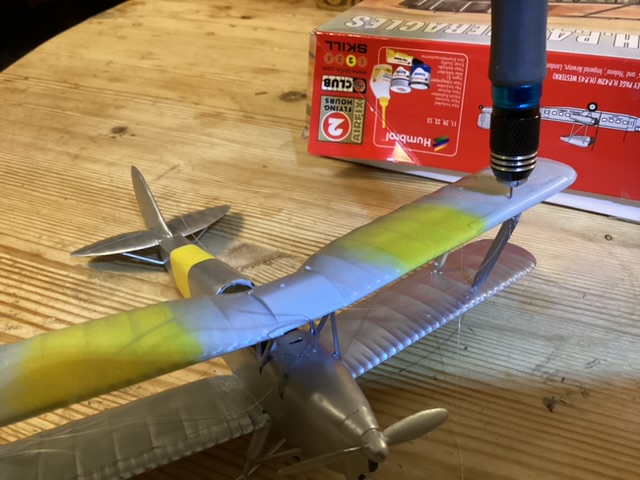
The applicator has a fairly fine nozzle that give pretty good control once the first bit has gone
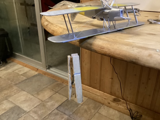
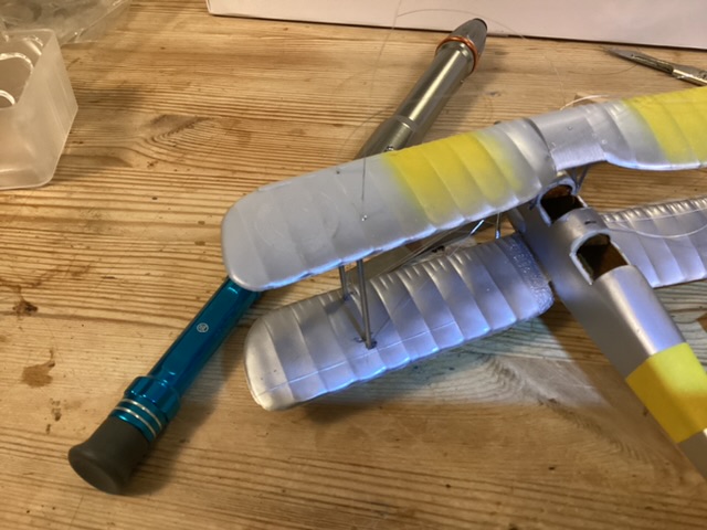
Dot a bit of adhesive on the inside of each joint with the line slack. Attach a clothes peg to the end of the line. This applies just enough tension to the line but without distorting the structure. Shine the uv torch on the joints for at least 5 secs each to set the joint. If using cyano, tension first and use cocktail stick to apply cyano to line and hole. Wait to set.
Dot another blob of your chosen adhesive on the outside of each joint and set off. Flying wires done.
Bracing wires next. I already trapped a loop of line in the interplane strut mounting, take the ends, pass the rear one through the front hole in the lower wing and the front end through the rear hole, apply glue, tension with pegs, set glue, remove pegs, glue outer joints, done
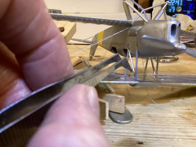
Some holes are difficult to reach, fine cranked tweezers will get them. Note the cabane bracing lines are crossed.
 Cabane bracing done
Difficult to see in this photo, 2 lines have been passed through the hole just outboard of the rear cabane strut and secured. One passes to the lower end of the front strut, the other to the lower end of the rear strut. Tension them and check they don’t foul any of the flying wires already installed. If they do, take them out of the hole, pass them the other side of the offending wire, re-thread and re-tension. Check again. Release tension, apply glue, tension, secure outside of joint. Landing wires done
1 Like
I timed the second side, took 22 minutes for 7 joints (the HP O/400 had more than 100 joints in the wings, but it was essentially the same as the above, just repeated)
This morning I trimmed the long ends and started to get the unpainted areas prepped. Main thing was whether the new UV glue could be trimmed and sanded. Good news, it can be trimmed close to the surface of the wing with a scalpel and then sanded smooth.
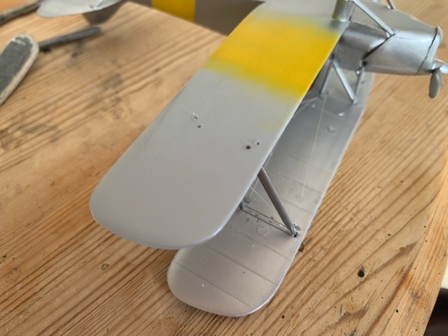
The top wing after paining

The underside, few signs of the rigging in the surface.
Taken all in all I like the UV glue, very controllable, seems strong, excess easy to remove.
2 Likes
Wow, this is great. I’ve avoided thru holes on the top wing to try and keep it looking neat. I glue the lines into blind holes in the top wing then install the wing. But the rat’s nest of wires makes the assembly a bit crazy. On the SPAD I built last year, I was able to leave the radiator off and pull the interplane lines out thru the cockpit or front end.
1 Like
The biggest problem to drilling the top wing I found was the glue giving way when the excess is removed. By glueing inside the wing and outsideI seem to have avoided this. I have always drilled through the wing but always managed to hide it. It helps that the decals often coincide with rigging points. I guess you do what works for you. I will be using the UV glue again though, should be good for transparencies, supposed to set clear.