Rye Field Sherman Firefly Build

This week I started on the RFM Firefly kit. I’m planning on completing it as a vehicle one of the Polish armored units which fought in Normandy. I’ll decide on the markings and version after I receive a Firefly reference book which I have on order. This is my first ever multi-piece-hull AFV kit, and I am pleased with how well the parts have fit together so far.


The quality of small details is amazing, such as the crisply molded casting numbers on the transmission housing. Some of the parts however seem to have been created in an unnecessarily complex fashion such as the idler wheels, each of which consist of 6 parts (!).


I am curious as to what this tiny 5 piece component represents. According to the instructions, it will be mounted on the rear plate, near the engine access doors. An exhaust vent perhaps?

That’s all for now, getting ready to build the complex and apparently workable bogie trucks.

10 Likes

It is a smoke grenade housing, I asked about leaving it off and the answers were 50/50 either way. I left mine off because I felt it was “too busy” on the rear engine access.

I have a RFM Firefly waiting on the shelf so I’ll be watch your build.

bruce

2 Likes

I too have it in the stash and will be watching closely.

1 Like

Wow!
Never would have guessed about the smoke grenade housing. If I can’t find any photos of it in my references I may not use it. There are also a pair of unusual looking ‘braces’? or ‘brackets’ which the instructions show as being mounted on the insides of the front fenders (parts D14, D15). I have no idea what these devices are either, nor have I ever seen photos of these devices on a Firefly. The instruction booklet is very clear and easy to follow, however it would be nice if a few of these parts were named.

In addition, for a model which features a plethora of variant parts, i.e. 3 different return rollers, 2 types of muzzle brakes, 3 types of drive sprockets, etc., a bit of historical explanation could be useful.
I strongly recommend a decent reference book for this vehicle, as the documentation in the kit is strictly limited to assembly and decal placement.

1 Like

I have one in my stash so will be following.
I have been putting off starting it because like one comment above I have no idea how you are supposed to choose which of the optional parts to put on.

1 Like

the parts you mention were part of a disguise, basically a frame and canvas disguise to make the tank look like a lorry I believe. For the moment I can’t recall its exact name but the little PE parts down the hull side were part of the fixings too.

I built the Tasca Firefly a while back and seeing this in the plastic I’m tempted. So will follow your progress.

Keith

1 Like

nice work! Great to see your pics. A great resource for info is this site: Sherman minutia homepage

specifically http://the.shadock.free.fr/sherman_minutia/manufacturer/m4a4/m4a4_variants.html

For drive sprockets, the most common seen on Chrysler tanks (like your Firefly VC) was this one sherman_sprocket4

One thing you might want to do is to putty in the seams where the bulges of your differential cover meet the body of the cover. See this picture 3pieces_differential1

Hope these help!

1 Like

I am sure this is supposed to help us modellers but I was more confused reconciling the kit parts/options after reading it than before LOL
http://the.shadock.free.fr/sherman_minutia/index.html
EDIT
@ericadeane you beat me too it!

Thanks for the clarification, yes this makes sense. I was wondering about the tiny squares on the hull sides too, as I had seen these in some photographs. I think I’ll be leaving these features off.

Thank you for sharing the transmission cover photo, I was planning to putty those seams since they do not match any photos which I’ve viewed.

Today I began the assembly of the workable, moving bogie trucks. Here are the parts needed to assemble 1 bogie truck. Note: each of those road wheels consist of 2 pieces.

Here is a look at the 3 types of return rollers to choose from. I decided to use the roller as illustrated in the instruction book. I’m totally astonished as to why RFM went to the extent of molding 3 types of return rollers, especially since the differences between the types are negligible. Also, those little round ‘nubs’ at the top of the sprue above the return rollers are bolt heads to be cut off and used in various assembly stages. I actually have to trim off 2 of the small size ones to place on the curved track guide on the top of each bogie truck.

Finally, after over an hour of cutting, trimming the numerous mold seams, sanding and assembly, I have actually nearly finished 1 bogie truck. (I haven’t yet added the 2 aforementioned bolt heads). Amazingly, the suspension is moveable, which would be nice for anyone planning to place their Firefly on broken terrain in a diorama. Apparently the suspension system will be the most time consuming portion of this entire project (I’m saying to myself as I gaze longingly at the Tamiya M4 Early Production over there in my ‘to build’ stash).

7 Likes

I took a bit of a break from this project while awaited the delivery of a Firefly reference book which I had ordered. After a bit of research of Polish Firefly photos, I have settled on a particular vehicle which fought in the action at Falaise in Normandy.
Based on the photos which I have seen, I am in need of sourcing some spare tracks of the same type as on the running gear of this vehicle. The kit only provides about 6 or 8 spare links which are to be mounted on the racks on the glacis, however the vehicle which I have chosen to model had additional tracks welded on to the front sides of the turret. My references indicate that the tracks for this vehicle are of the T54E1 type, however I have been unsuccessful as yet in locating any aftermarket sources for these types of tracks.

I have completed the assembly of the bogie trucks (including adding the tiny bolts on the track skids), and I am happy to report that all six units are ‘workable’. I have begun the assembly of the tracks using the assembly jigs which were provided in the kit. The tracks appear to be over-engineered at first glance, however they were actually surprisingly easy to assemble.

The ease of the track assembly was primarily due to my review of Part 1 of the excellent video tutorial of this kit on YouTube by Champion scale modeling. I strongly recommend the use of super glue for attaching the chevron outer pads of the tracks as was demonstrated in this video.

A few personal observations so far on the design of this kit…
The plastic seems to be rather ‘soft’ compared to Tamiya or AFV Club. I have noticed that when I cut the parts from the sprue using my purpose-built Xuron sprue cutter, the softness of the plastic seems to result in tiny, somewhat ‘squished nubs’ which require cleanup. This is especially time consuming during the assembly of the tracks. I have more than doubled the build time so far due the necessity of cleaning these parts to an extent which I have not had to do with kits from other manufacturers.
That being said, the quality of the small details molded in to some of the tinier parts are amazing, and there is absolutely no flash of any kind anywhere. In general, I am quite pleased with the project even though the build is taking a bit longer than I had expected.
I have 2 other Rye Field kits in the ‘to build’ que, both of which have interiors… what am I getting myself in to?

4 Likes

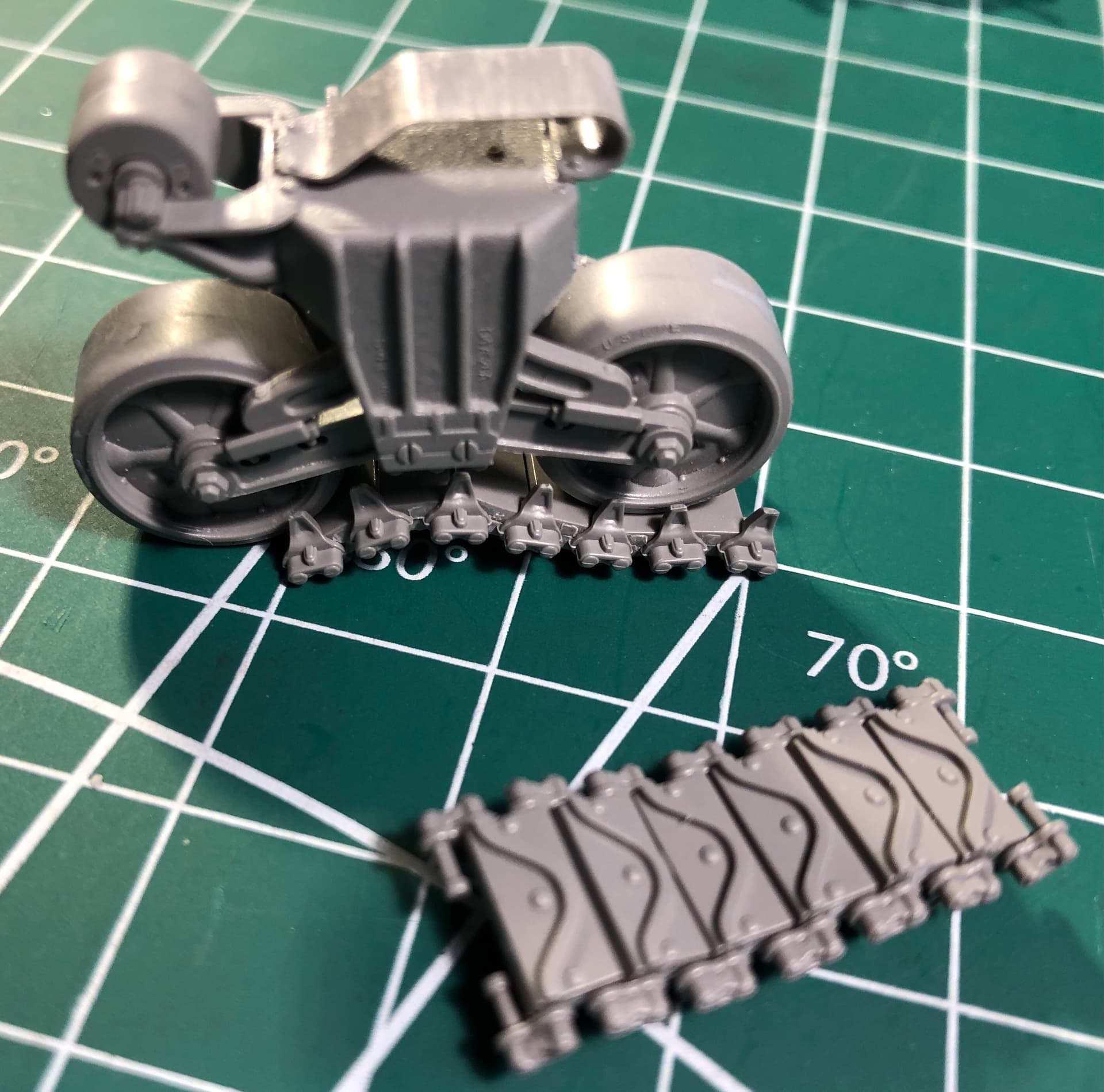
Having finally completed all of the track and suspension assemblies, I have been working off and on for the past week on the Firefly’s hull.


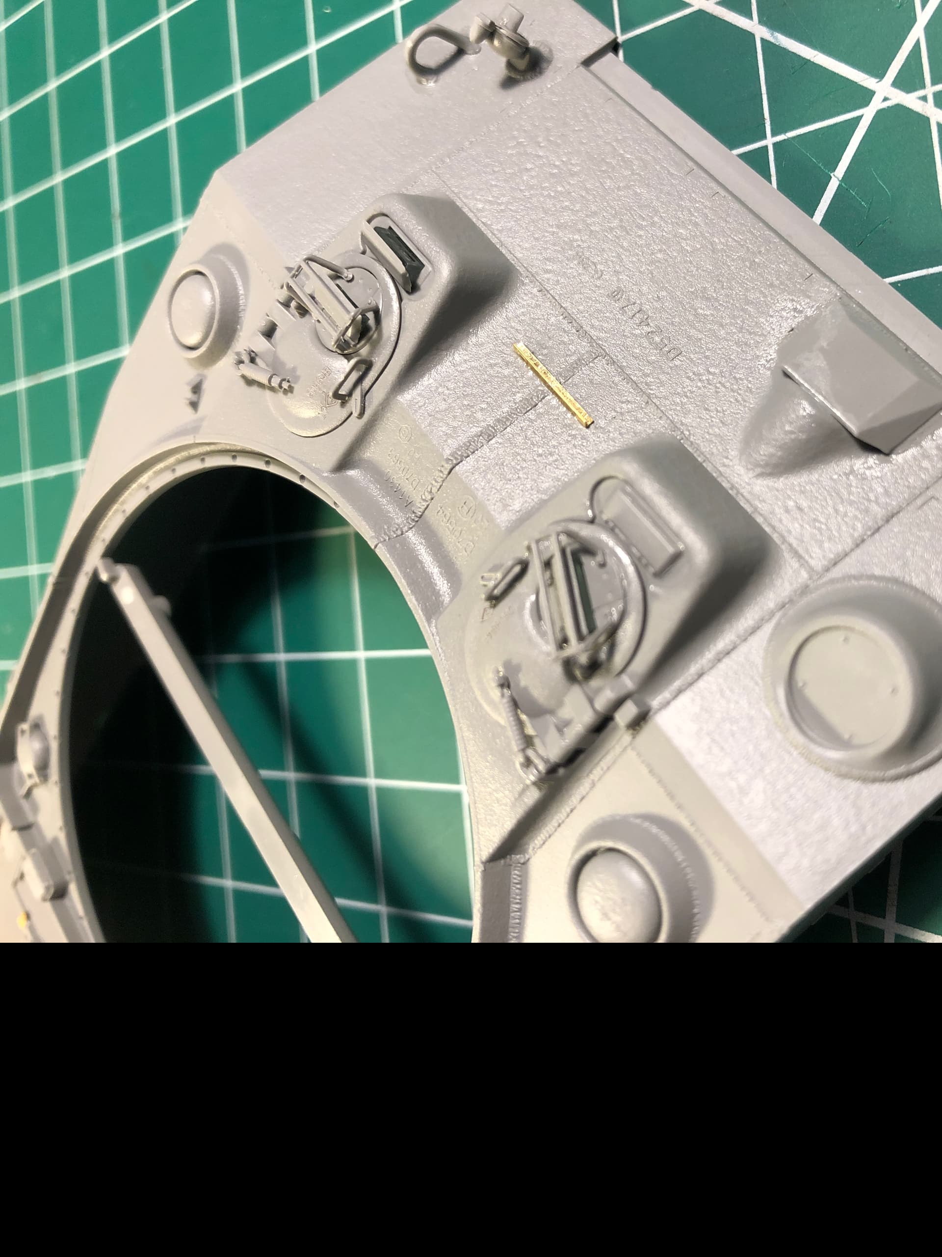
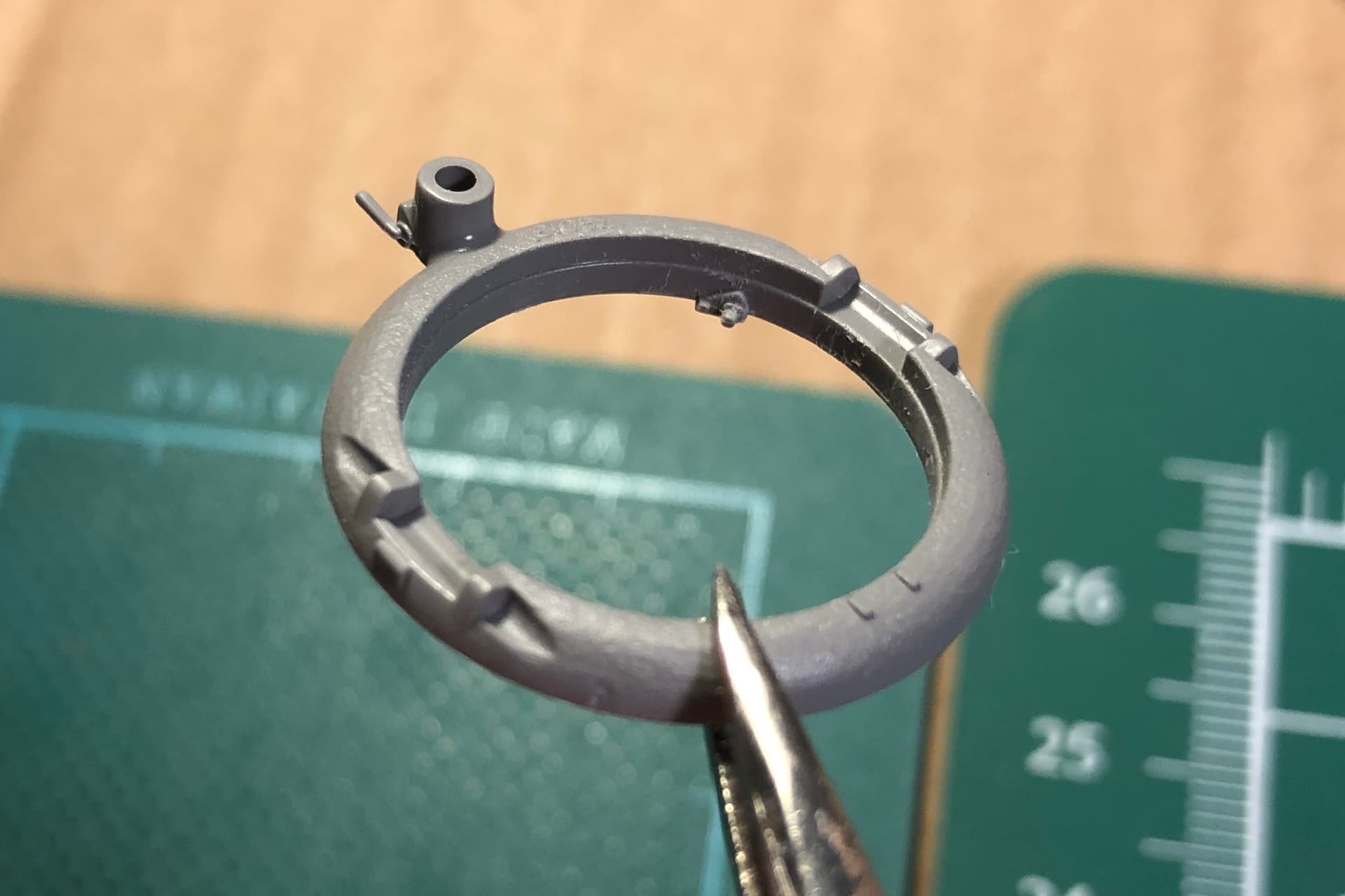
I have decided to model this vehicle in a ‘buttoned-up’ configuration, with the exception of the T/C’s hatch, in which I hope to find a suitable figure to position therein with his head barely poking out of the hatch. I see no real need to display the other hatches in an opened position considering the total absence of any interior details. A bit of a shame considering the fine details on the hatch interiors, including the exquisitely detailed periscopes.

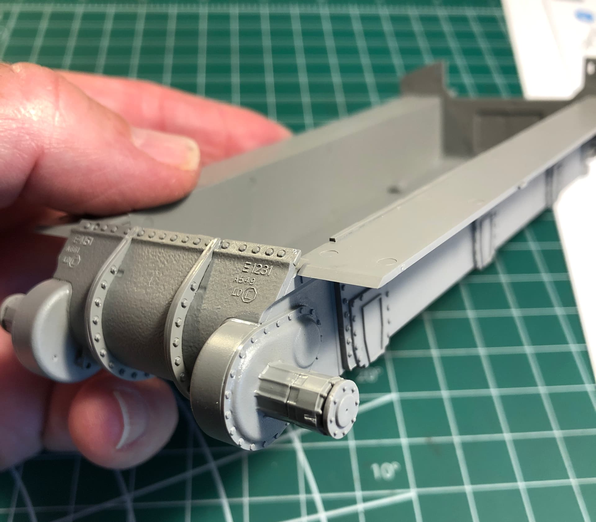
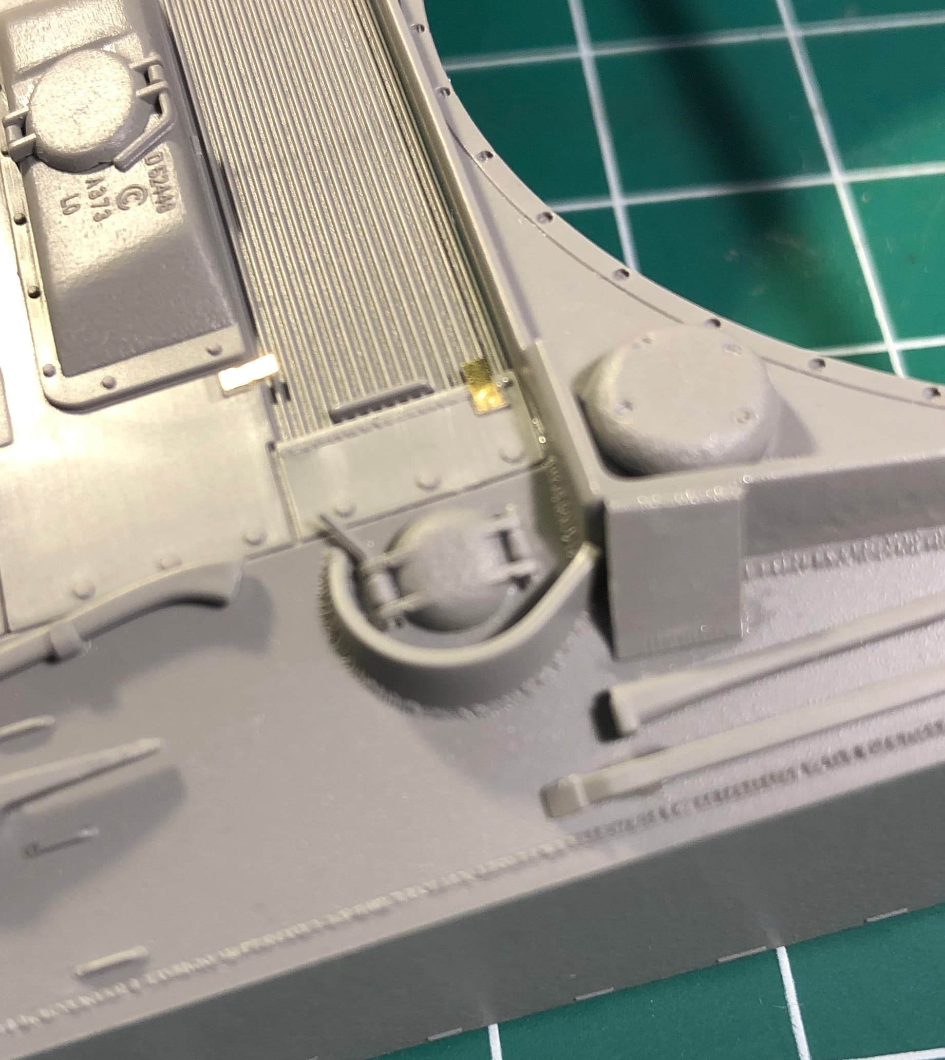
Another example of fine details are in the area of the hull fuel fill ports. The very nice fuel tank caps will be hidden once the armored fuel filler covers are installed, and there is no option for leaving these covers in an opened position without extensive modifications.


I really love the attractive, and understated weld details on even the smallest parts… check out the delicately molded plastic latches on the armored fuel filler covers.
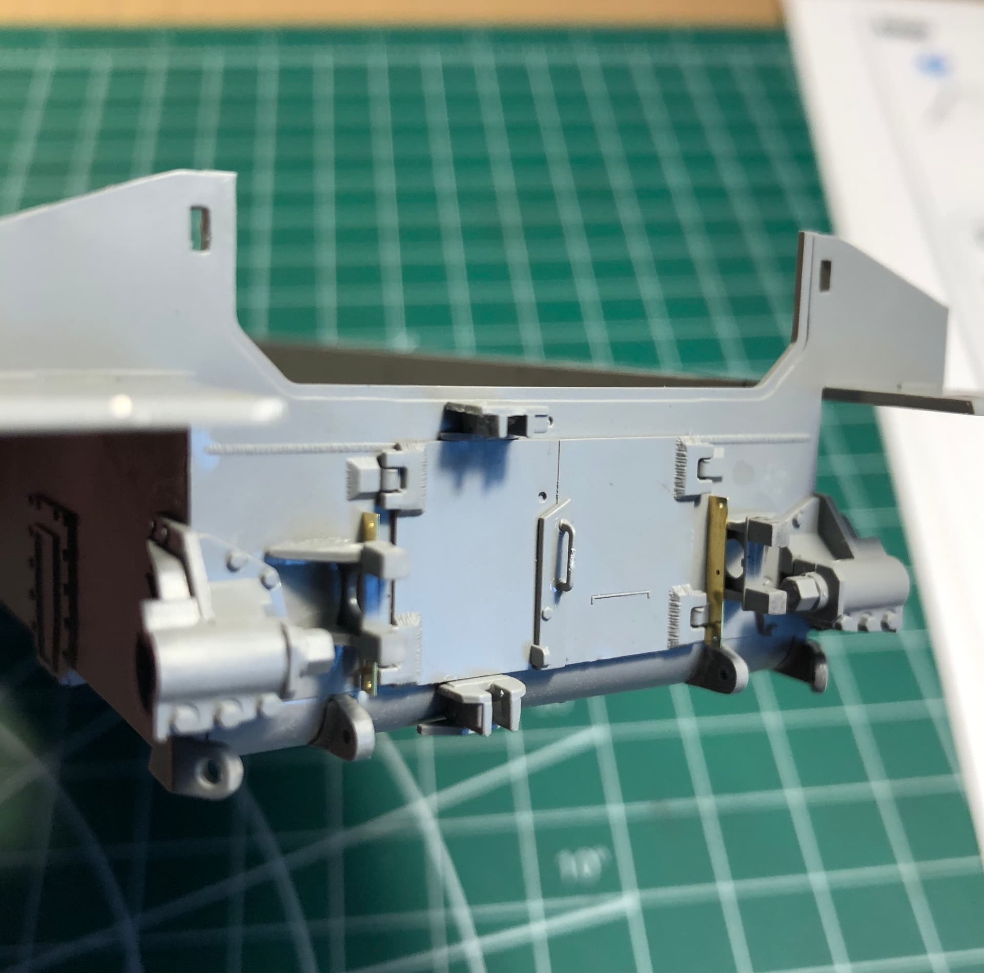
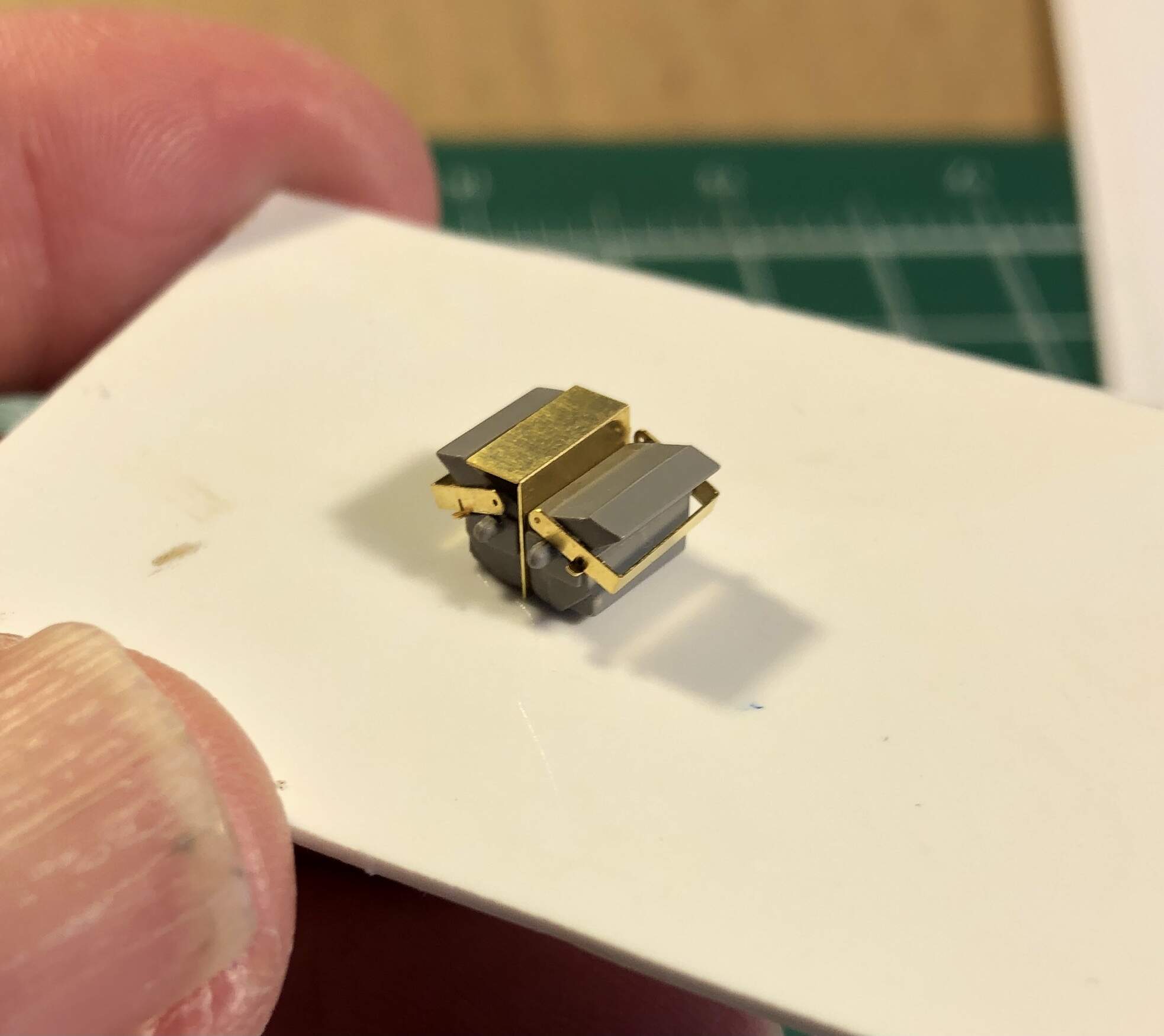
There is quite a bit of very tiny photo etch parts included in this kit, however the brass used on these parts seems to be of a perfect ‘softness’ and the parts have been very easy to clean up, bend and install, more so than other brands which I have used in the past.

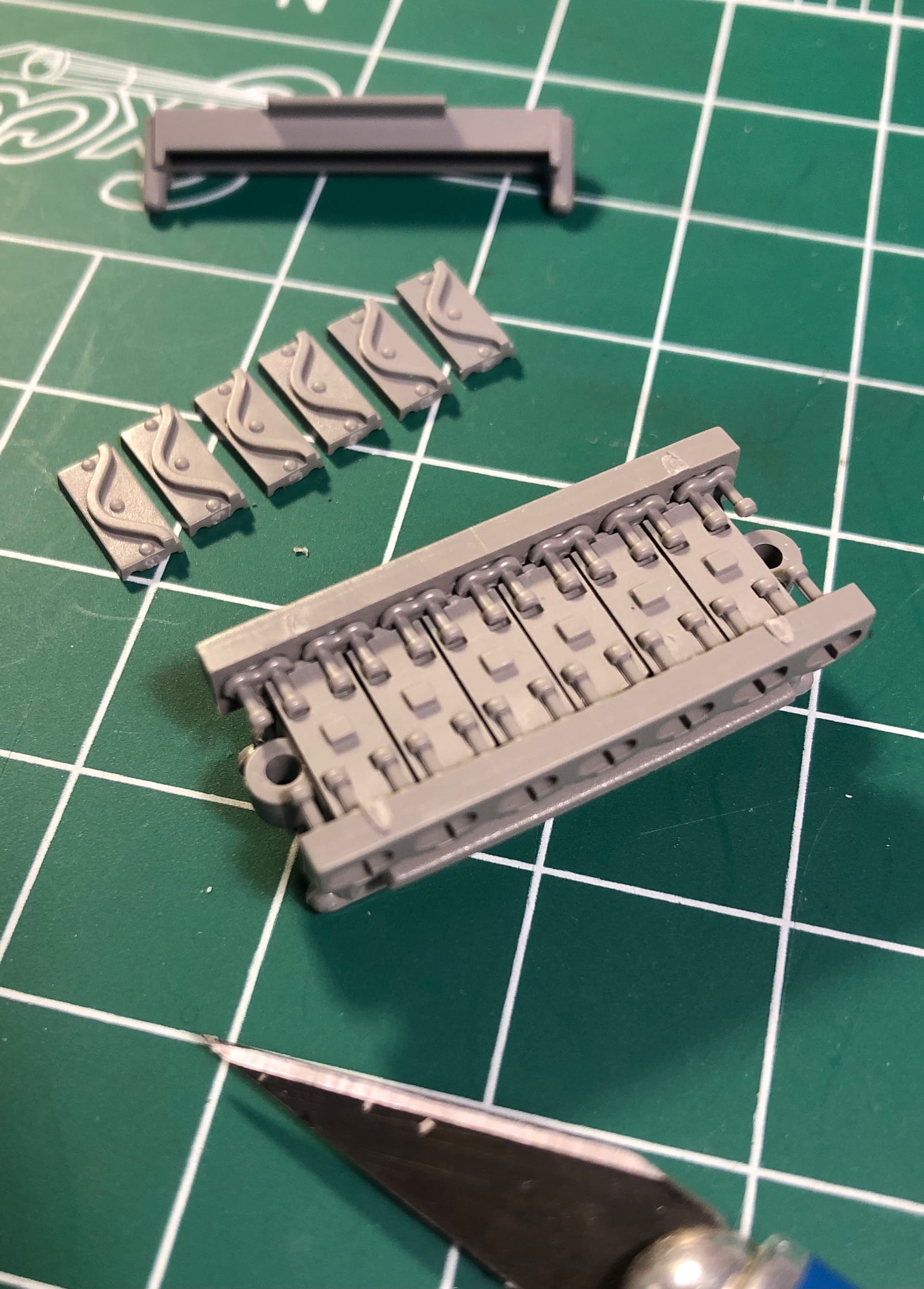
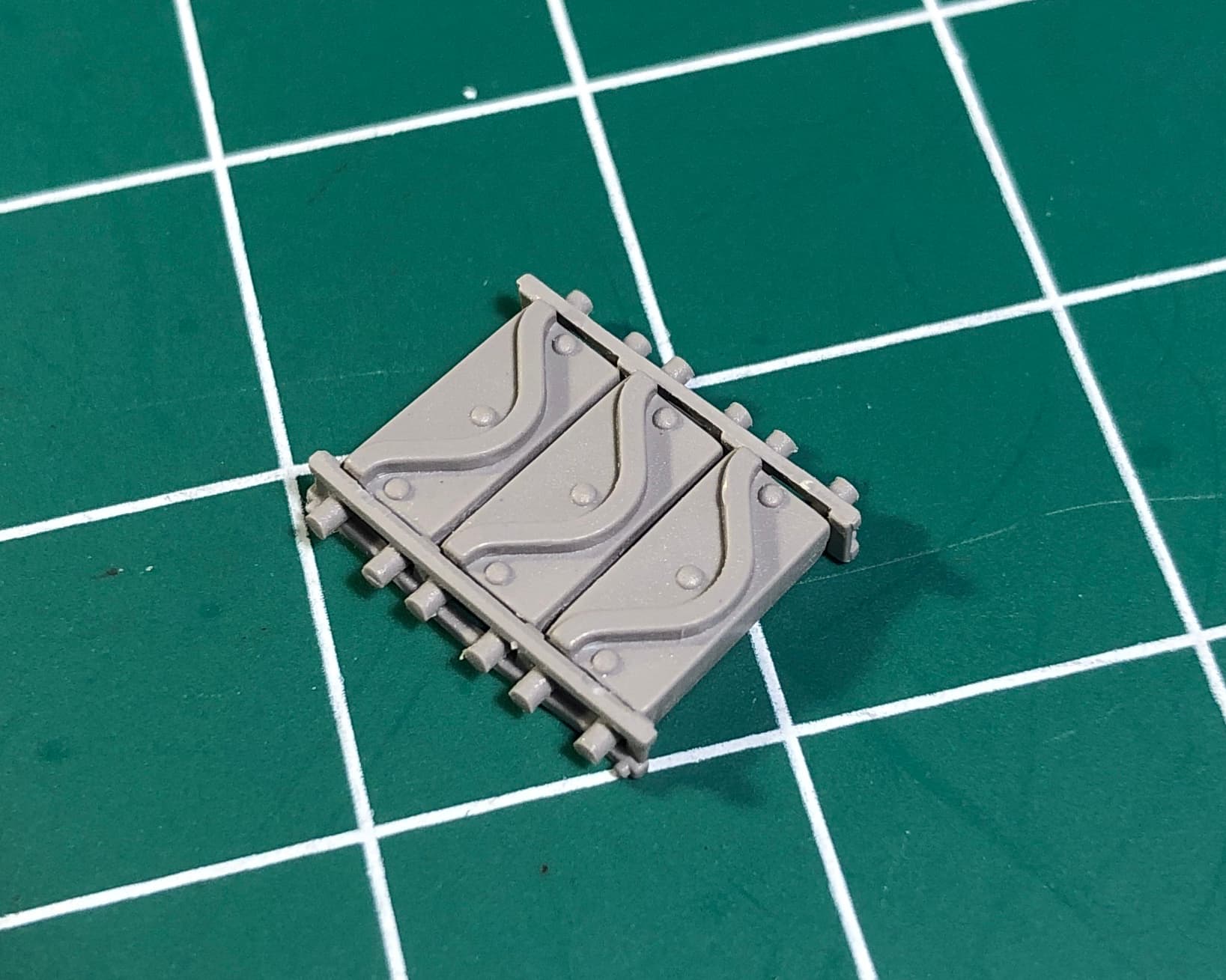
A notable exception regarding the photo etch parts would be for the spare track brackets. In this case I chose to use the plastic kit parts instead since these appeared to be of a more correct scale thickness, i.e. thicker than the photo etch parts. There are several areas of the assembly where the instructions allow for a choice of using either plastic or photo etch for some of the finer details.

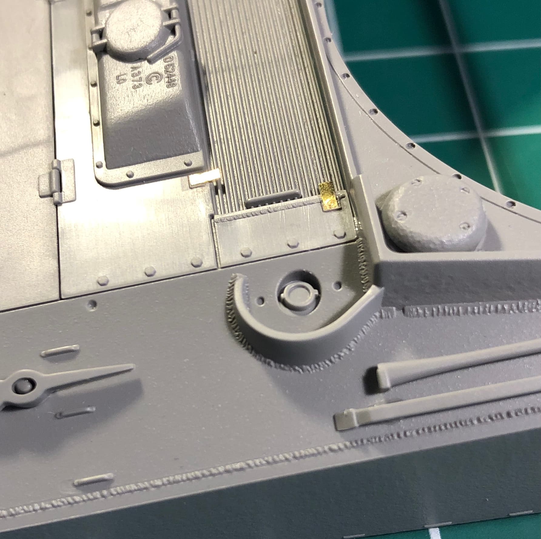
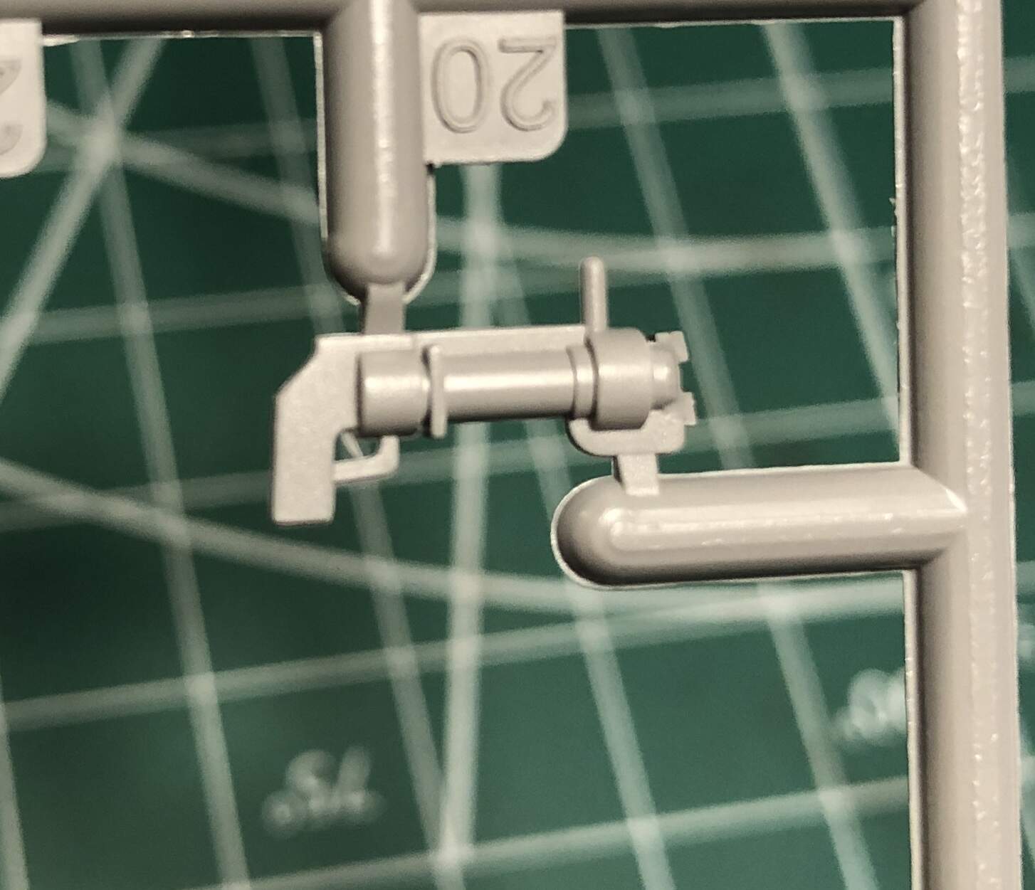
A word of CAUTION however regarding the main gun travel lock…
The Firefly vehicle which I have chosen to model requires that the travel lock be installed on the left side of the engine deck in a diagonal position. The instruction booklet displays diagrams for 2 manners of positioning the travel lock based on whether or not you are modeling an early or later series vehicle. Unfortunately after I had drilled the holes for the travel lock per the instruction diagram, I checked all of my reference photos and line drawings, and I noticed that the diagram on page 12 of the instructions for the ‘diagonal’ position travel lock indicated that the locating holes should be drilled in the incorrect location on the center engine deck access hatch, and not on the rearmost portion of the engine deck as was the case on actual vehicles. I have filled in the erroneous holes with putty, and after clean up, I will install the travel lock in the correct location.

Overall so far I am enjoying the construction of this kit, and I continue to be amazed by the beautiful, finely molded details. Considering the complexity of the multi-part engine deck hatches and their tiny photo etch details, I am actually amazed that this kit doesn’t include any interior engine details.
Although I can only imagine the complexity of a RFM Chrysler multi-bank engine!

4 Likes

Don’t forget the chain for the fuel cap handles!

I would love to add that detail if I knew of a source for such a small part. Considering the tiny parts included in this kit (separate injection molded wing nuts for example) I’m rather surprised that the chains were not included.

No one includes them-I use PE chains

2 Likes

I finally finished the upper hull assembly (leaving off the tail lights and their PE guards until just before painting). Here is the corrected positioning of the travel lock, per my reference photos and drawings. I love the tiny PE retaining latch assembly.

Moving on now to what is my usual favorite part of assembling AFV models, the turret and main armament. Once again, this area of the model is highly detailed, and includes some very detailed features which will not be visible after completion… such as the finely molded co-axial Browning machine gun. The casting texture on the gun mantlet is very nice, and the bolt and screw details on the mantlet are amazing. (I’ll show photos of these later). There is however, a fine yet clearly visible molding seam/groove on the side of the one piece cannon barrel which requires filling.

Another example of a nice yet totally unnecessary detail part which will not be visible after the model is assembled… the breech assembly of the turret roof mounted smoke bomb thrower. I am saving this part in the event I may need it in the future on another British tank which requires interior detailing.

Last night I began the assembly of the commander’s hatch area, and encountered yet another example of an unnecessarily complicated PE part installation. Note the photo etch ‘ring’ or liner which the instructions indicate should be installed on the interior of the hatch ring. The PE part is too long and overlaps by several millimeters when installed.

As you can see, I decided against including this part, which is unlikely to be visible anyway, even though I intend to leave this hatch open with a commander figure therein.

Overall, the fit of the plastic parts is definitely above average, and I have been using far less putty to fill gaps compared to other kits. I continue to be puzzled by the intentions of the designers of this fine kit. Considering the high quality of the molding and some of the details which will never be visible after assembly, it almost seems as if they intended to design this kit as a full interior model. A prime example is the multi part engine deck assembly. The engine hatches are molded in separate parts which would be appropriated if a detailed engine was included. That not being the case, the upper hull could have been molded in a single piece as most Tamiya kits are. On the front of the upper hull, there is a very finely detailed aperture where the bow machine gun would be installed, which features the tiniest bolt holes which I have ever seen molded in plastic. None of this detail will ever be visible again after the Firefly’s armored plate or a bow machine gun were to be installed.

More photos of the turret will be posted soon. I can hardly wait to weather this tank in the future, those fine molded textures and details will surely ‘pop’!

2 Likes

Just read through your build log and had to let you know that you are doing an excellent job of describing and pointing out assembly issues and letting us know what your thoughts are concerning this company’s effort on this subject. I’ll keep following along. Thanks for sharing and taking some very good photos as you progress through this build.

~ Eddy :tophat:

2 Likes

Thank you for your comments and reading about the build.
I apologize for not having posted anything recently, however I have been very busy with family/holiday events in the past month plus.
I plan on posting a few more pictures and commentary on the Firefly build in the next day or two.

1 Like