For winches driven at the bumper, the PTO would have to be constant-speed driving a prop shaft, and there would be a gearbox/clutch assembly at the winch that allowed for speed, direction, and “neutral” controls via levers.
1 Like
Nick, I am sorry for this entire brouhaha.
You, at first said (I think) “Front PTO” and so I started looking for a front mounted rotating flange that you could hook up accessories to, for instance to drive a saw mill or a small rock crusher off of.
Appologies for ever getting into all this. I should have just asked you directly in a PM. (As Robin has now suggested.)
ONE EXAMPLE: The WWII Chevy fire truck with front mounted Darley water pump has a PTO coming right off the engine main crank pulley and coming right out through a hole in the radiator. You had me looking for something similar to that.
1 Like
Nick and Tim: As to the “cube challenge” I failed that one for years! Rectangular gas tanks and tool boxes always a problem for me! But I came up with a work-around.
Build a solid shape out of appropriately sized Evergreen square stock and then wrap it with thin sheet stock. (Tamiya “Plastic Paper”) This trick took the “worry out of being square.”
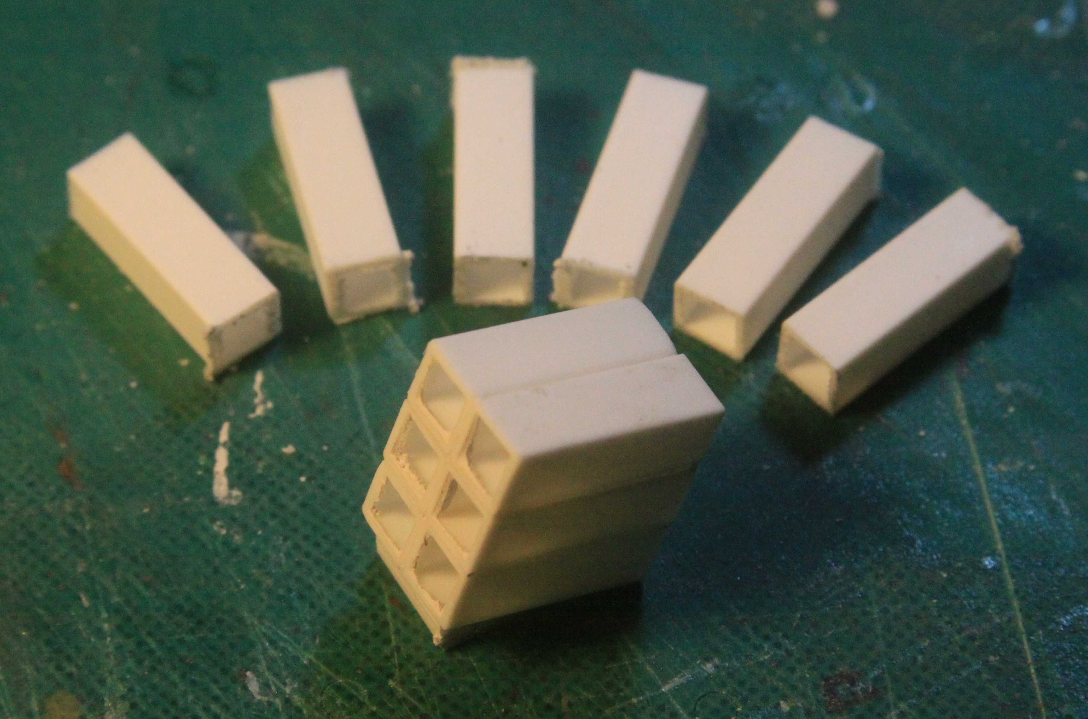
Tool Boxes for a big Russian 8x8:
Cut repetitive pieces of square tube in my homemade “chopper”. Glued them all together, sanded them smooth and then covered with plastic sheet stock.
Fuel Tanks:
For this one I used solid Evergreen square stock so I could safely sand the radius edges into the block before covering it with plastic sheet.

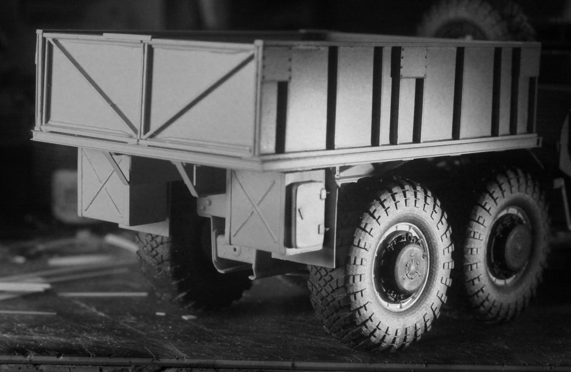
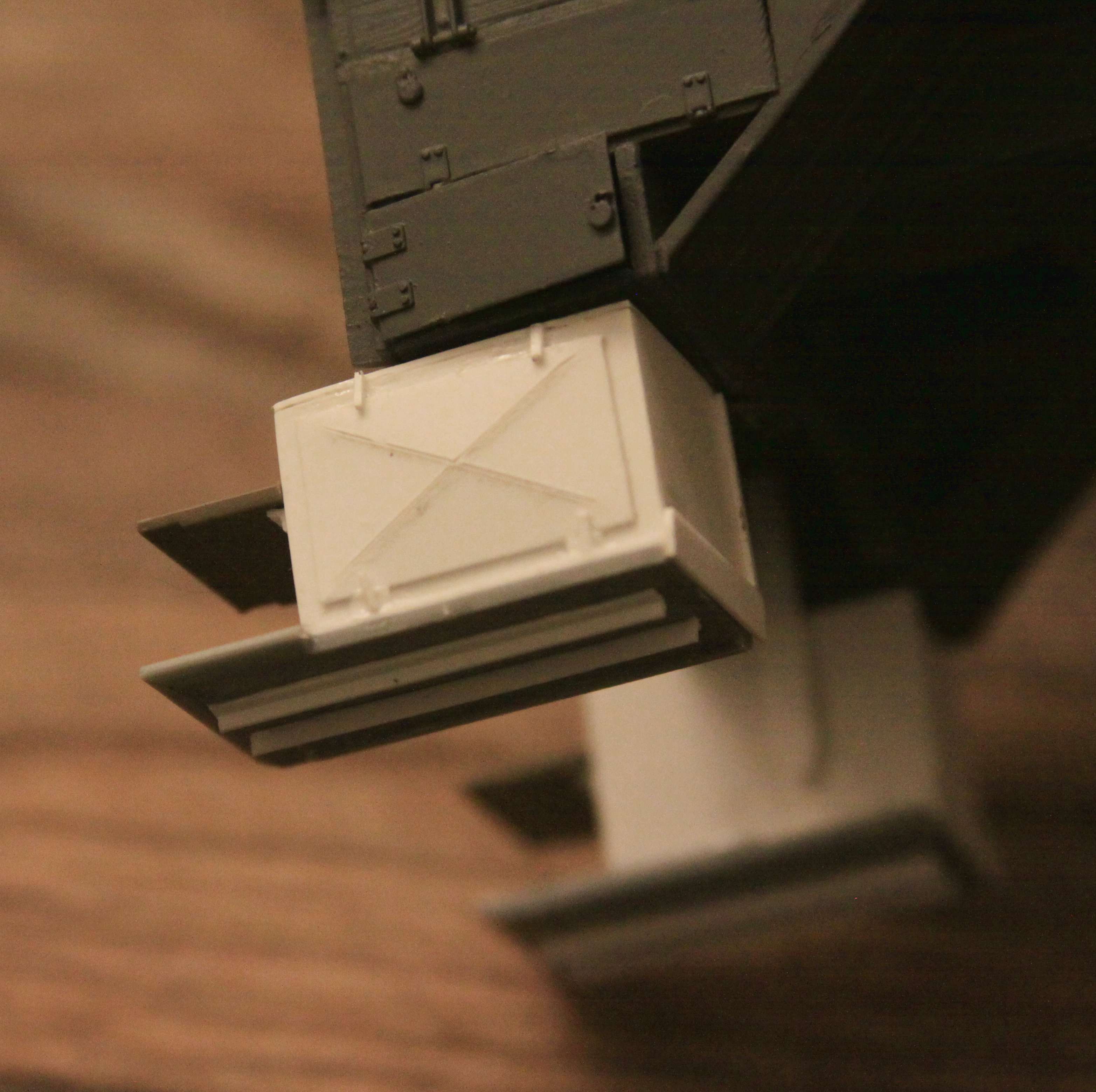
More Tool Boxes:
Again the solid shape was built up out of four equal length chuncks of Evergreen square stock and covered with thin sheet plastic.
FYI ~ The “X” shaped bead roll in the door I scribed from the back side using a regular ball point pen and a straight edge. I laid the work on my somewhat soft “cutting pad” so the piece could accept the indent of the scribe.
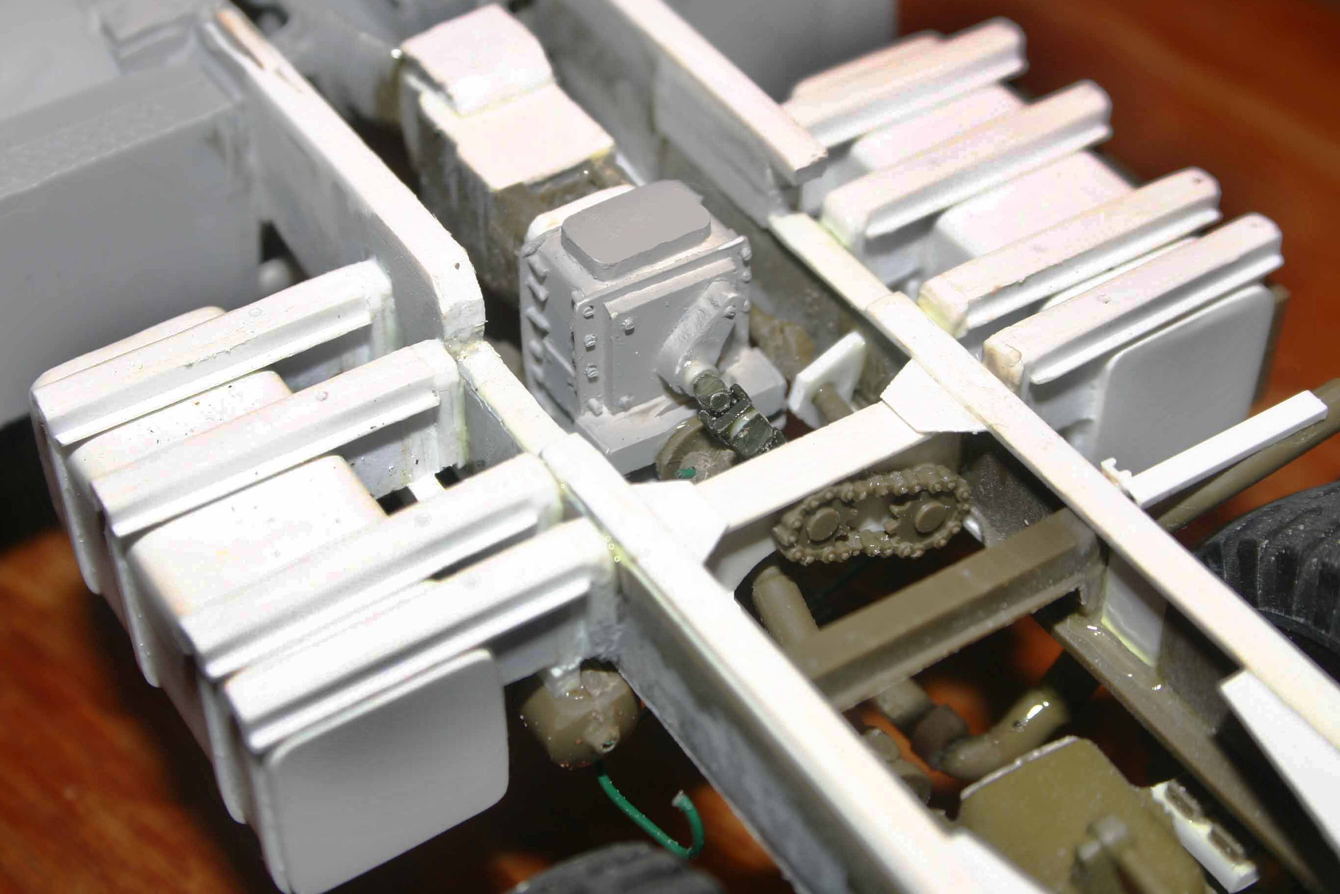
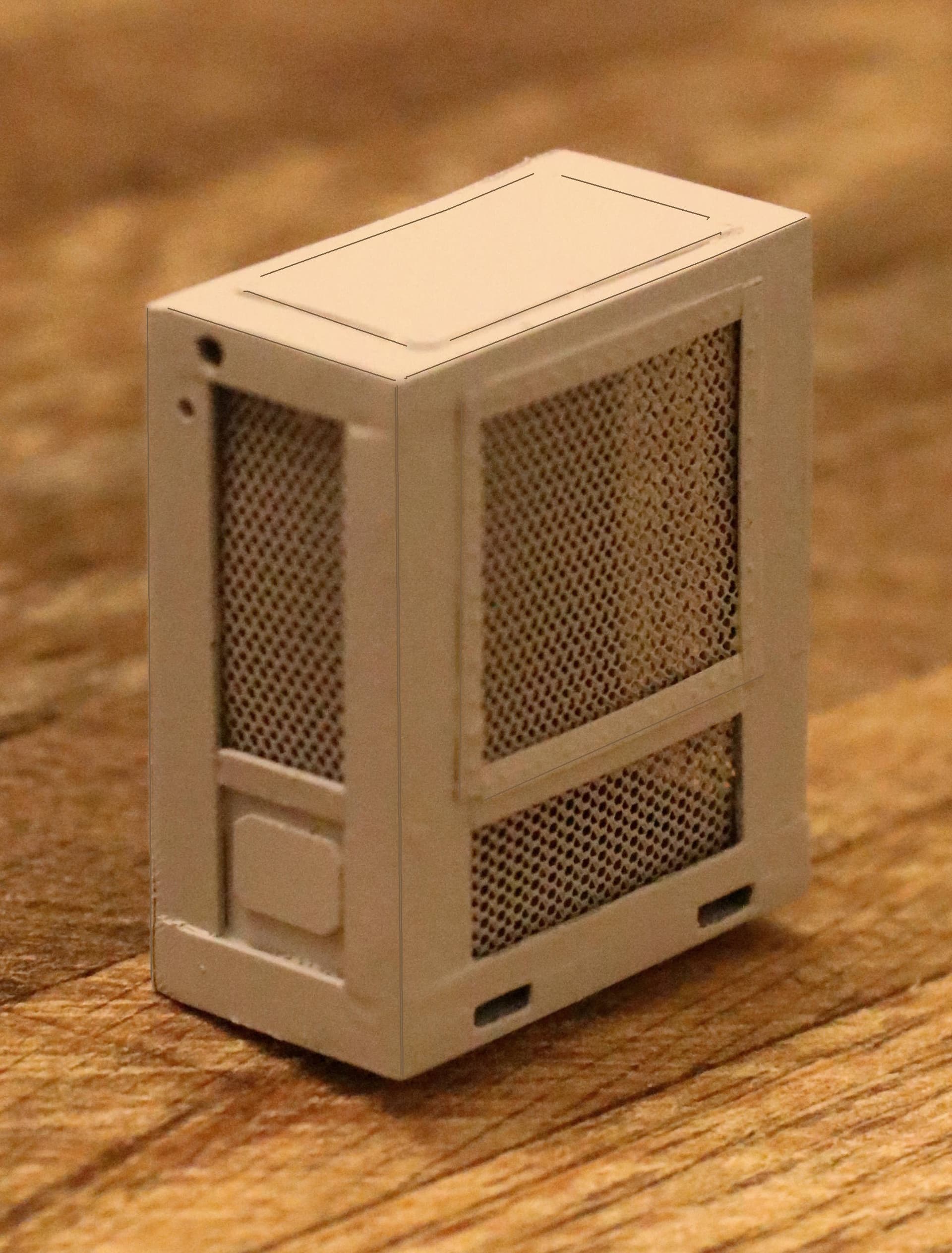
I did finally master the “Cube Challenge”. (Many years later.)
This generator and refrigeration unit are both built out of very thin Plastic Paper and Plastic Angle used to reenforce the corners from inside.


7 Likes
Barking,
Many thanks. They are actually quite easy. Well maybe that’s because I have been perfecting the technique for thirty plus years.
Thank you again
You put into words what I was trying to say… Maybe some of the Jack-a-lopes are right and I should shut my trap ![]()
![]()
![]()
![]()
![]()
Flipp’n AWESOME WORK
So much great information in this thread .
That’s a really simple/cool way to make bead rolled panels. I might even be capable of that. Thanks!
Gotta admit, after a lifetime of building I still fail the cube test 50% of the time! The good thing about Evergreen is there’s always more to redo my mistakes…
2 Likes
Hi Mike - no reason to apologize,
This is a “forum” after all ![]() , and questions are part of the deal! As for the “front PTO” - yes, for as long as I can remember, I have used the term in this context as slang to mean a front, PTO driven winch - if this were a full blog on a build, I probably wouldn’t have been so casual with the language.
, and questions are part of the deal! As for the “front PTO” - yes, for as long as I can remember, I have used the term in this context as slang to mean a front, PTO driven winch - if this were a full blog on a build, I probably wouldn’t have been so casual with the language.
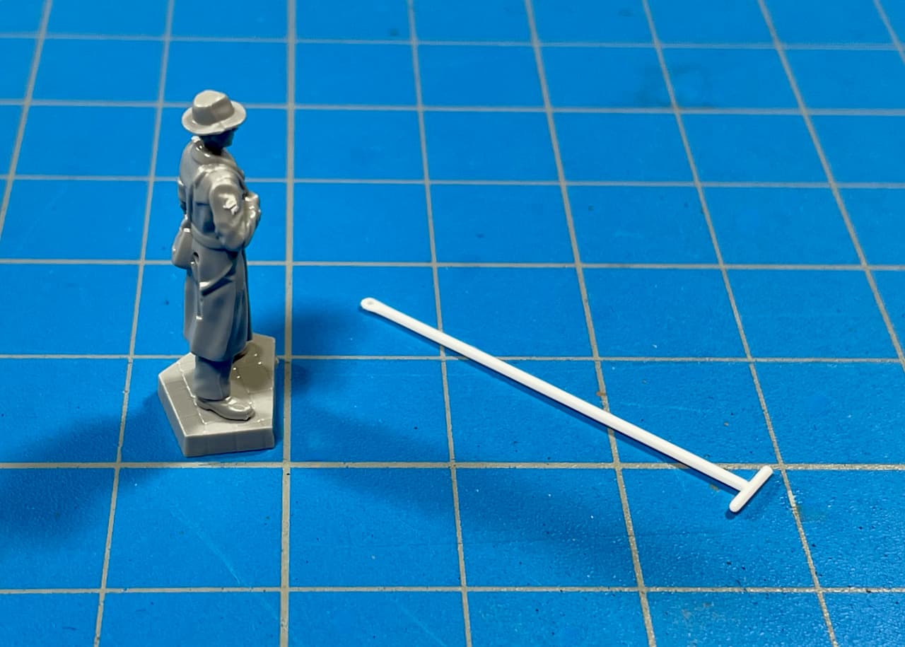
Let’s look on the upside - we all learned a bit more about how PTO’s work, and thanks to @barkingdigger we now know how a PTO driven front winch is operated while standing nearby - I always wondered about that!
I worked for a guy as a carpenter an embarrassingly long time ago - he had a one-ton Dodge 4 x 4 with a 4 speed, utility bed, and a PTO driven winch up front - what a truck!! Every now and then he’d “let” me drive it to the hardware store or lumber yard! ahhh simpler times!
Cheers
Nick
2 Likes
Just trying to drop a few modeling hints here and there.
I hope others will do the same because I am not done learning either.
My education will end the day I die!
4 Likes
We may argue that this is neither a scratch build nor a conversion???
I say it is both.
I have always had a pet peeve (just one?) most frequently seen in the early days of softskin armor modeling. *(Is that an oxymoron???)
That is, models offered with just a “profile” engine oil pan and the rest of the engine opening is enclosed with just a large flat plate when seen from below.
I don’t require a full engine in a model but at least give us the hint of the larger engine structure and the open space surrounding it.
I was very surprised to again encounter this detailing short cut in the recently offered Mk23 heavy Marine truck.
Here is my take on a repair for this problem:
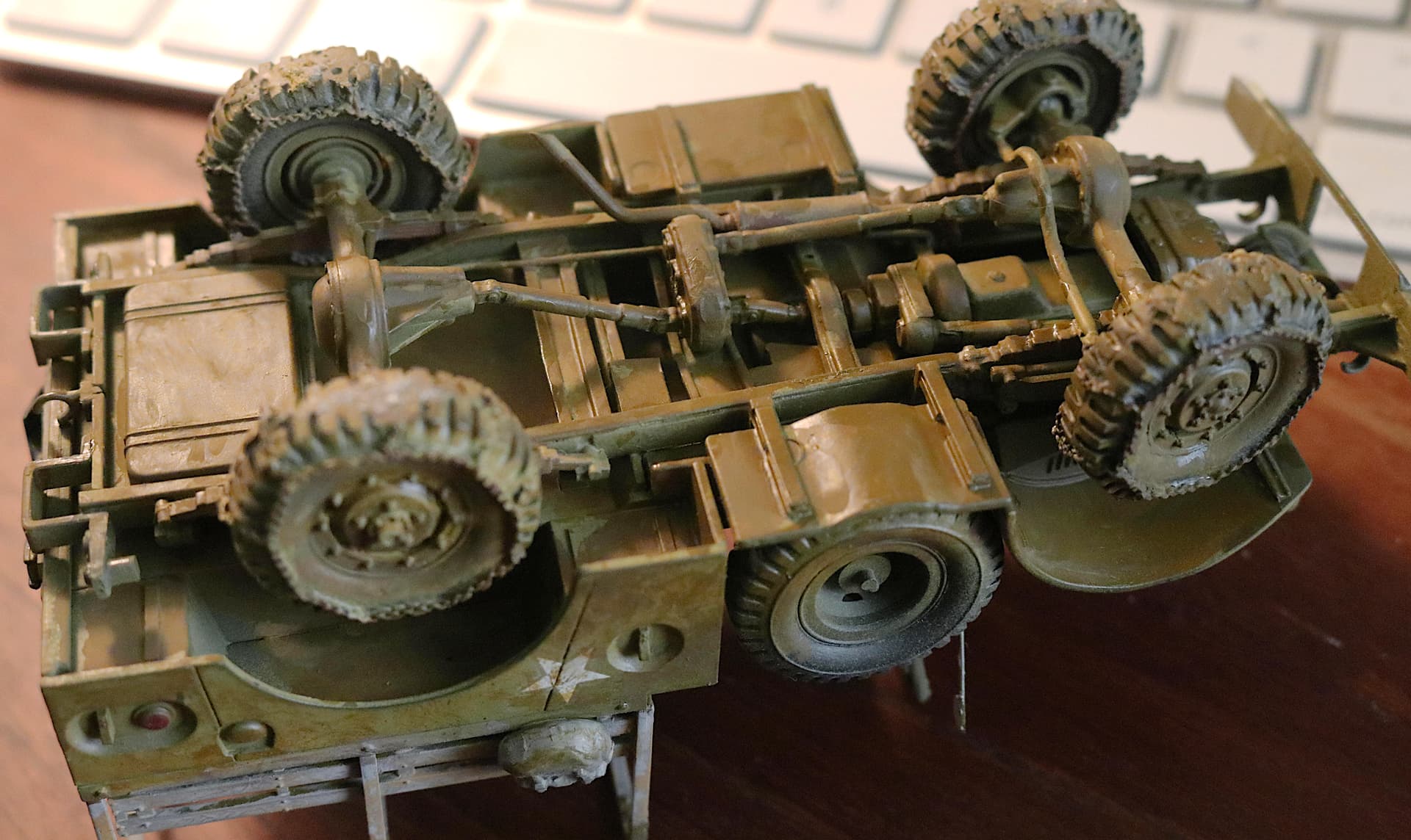
As to the Mk23 Truck:
- Remove the areas seen in white, leaving only the engine supports that are actually there on the real truck. -
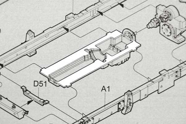
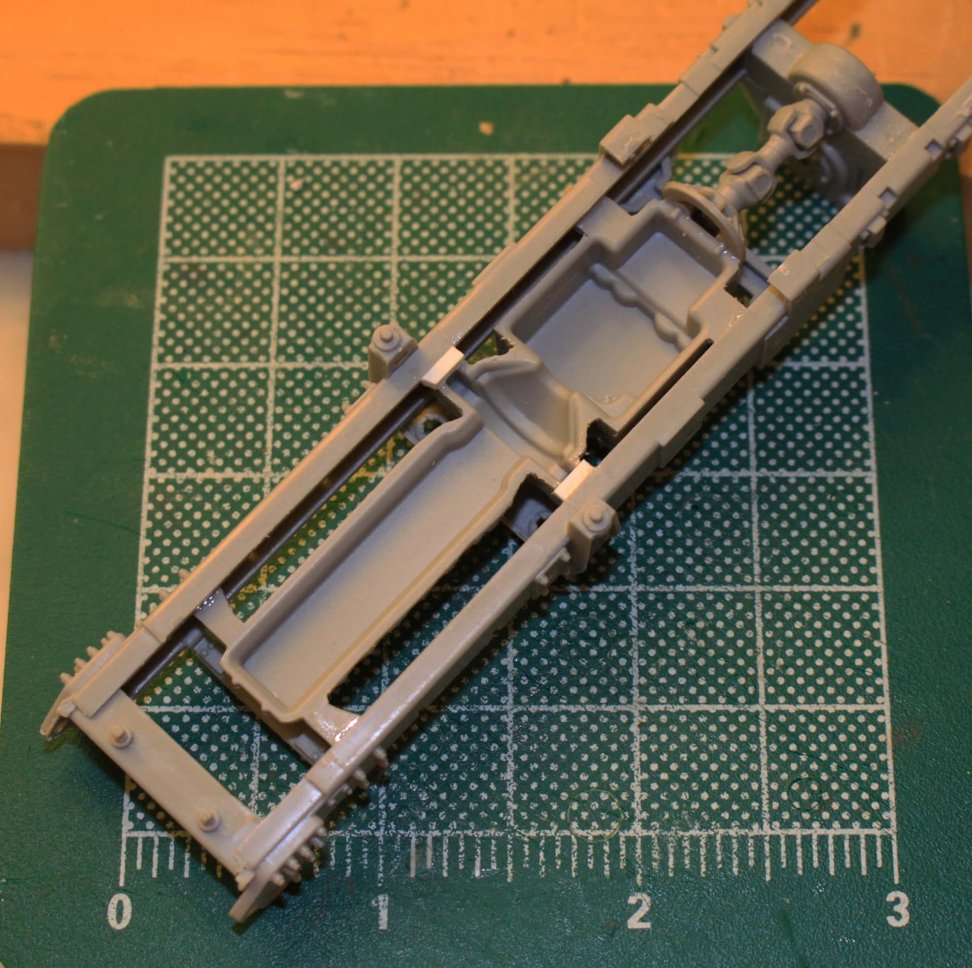
- Build up a partial engine and transmission profile -
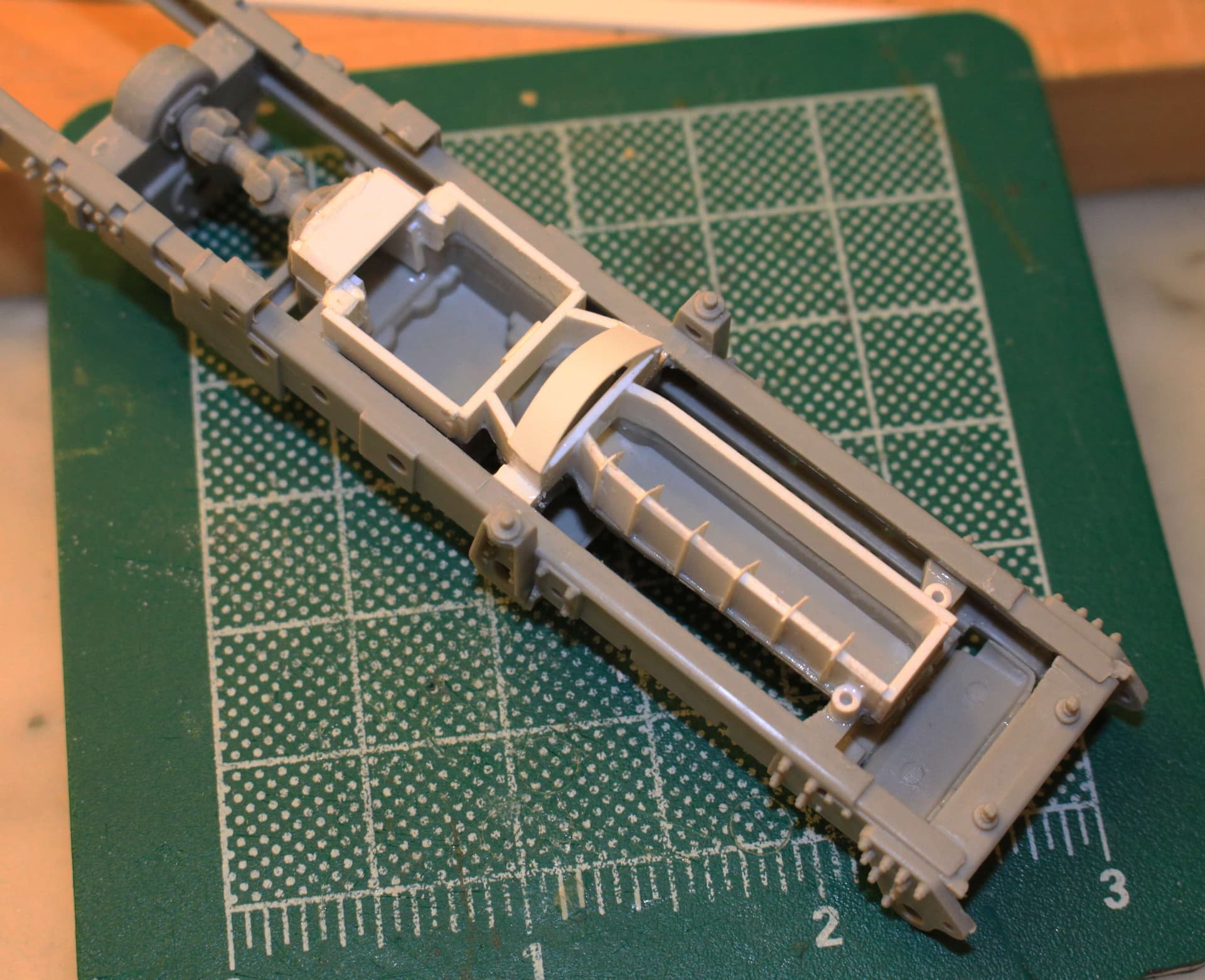
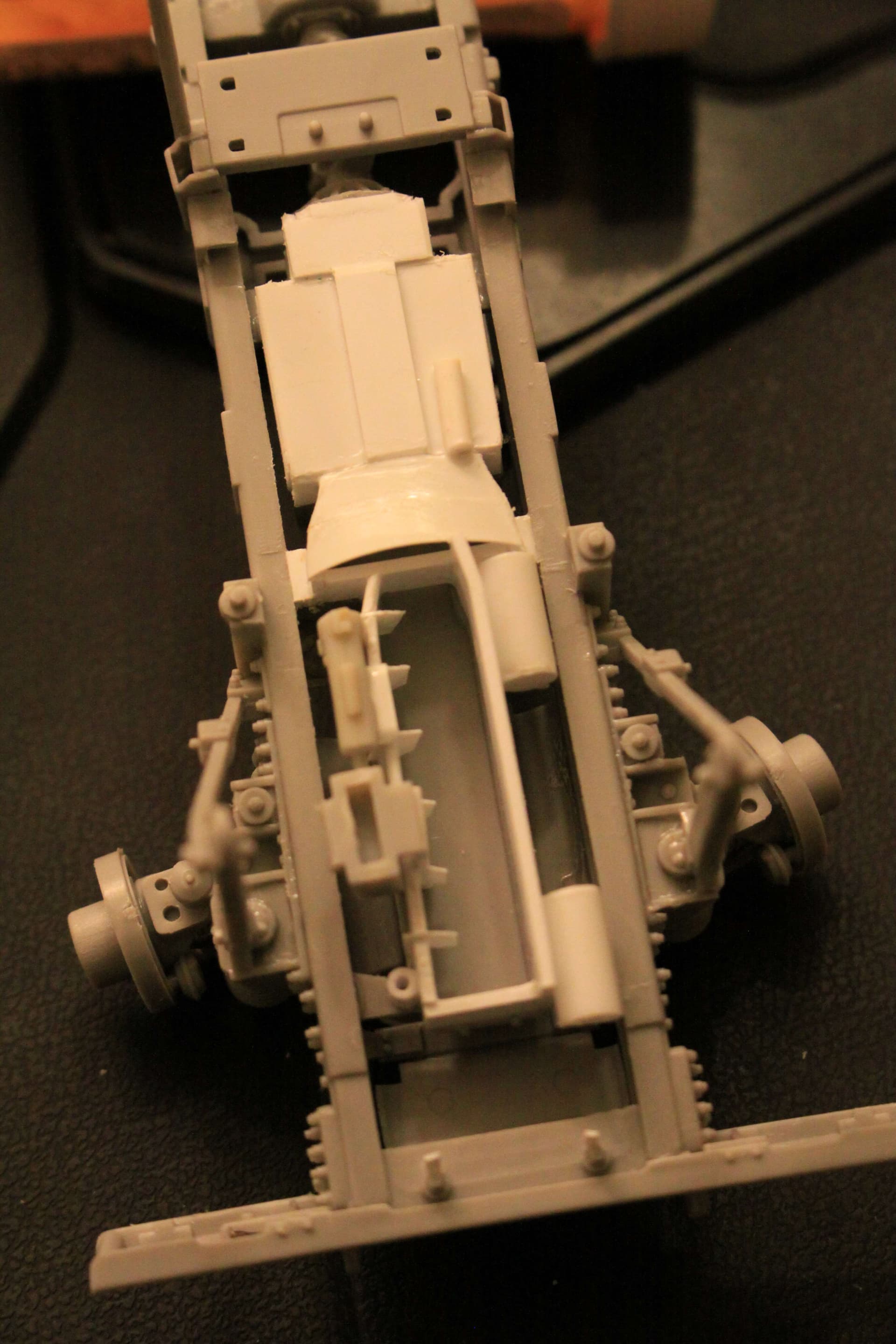
- I know, I know who can even see it for all that massive Oshkosh TAK-4 suspension? (But I know it is there!)-
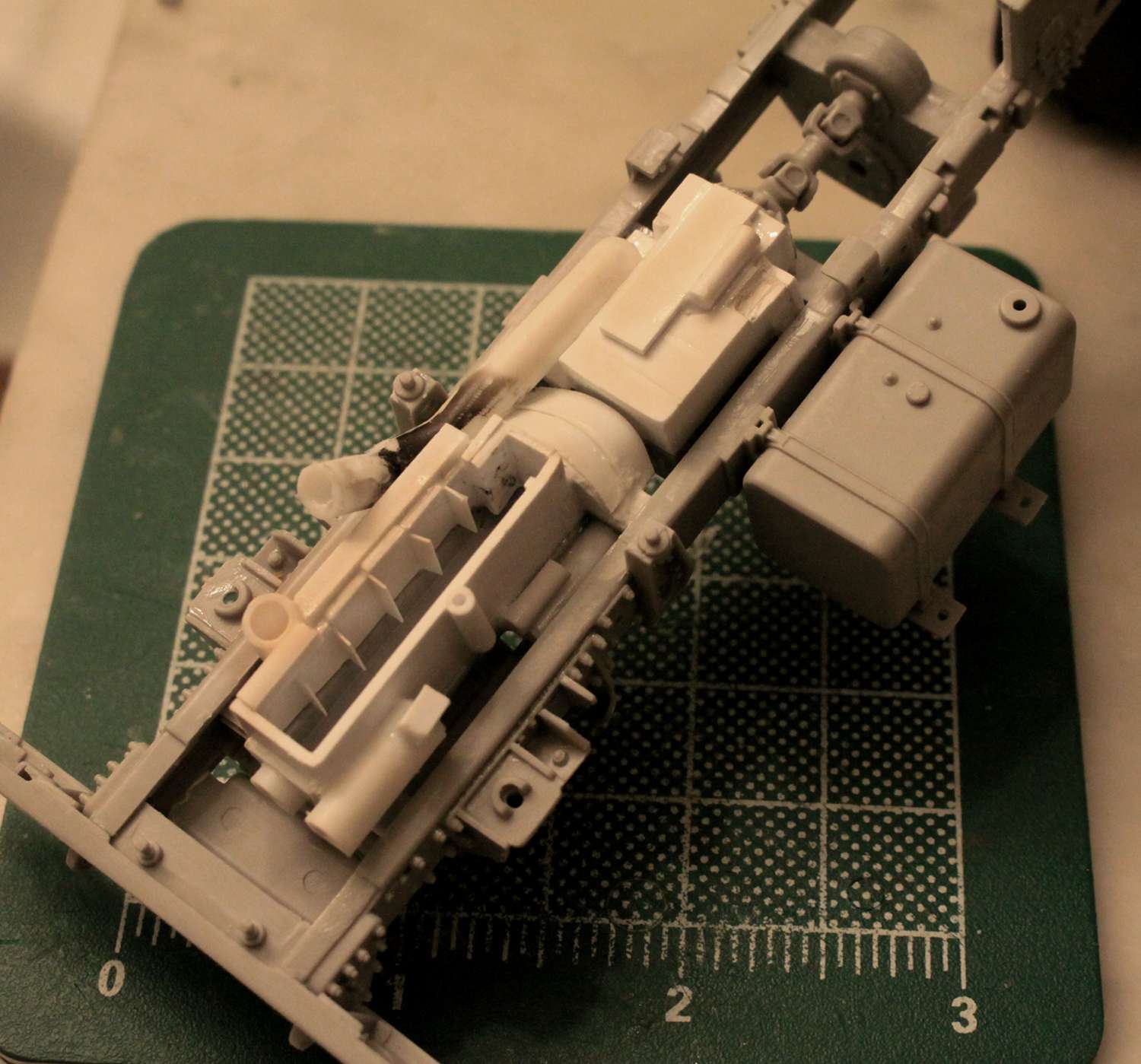
- I chose to build two variants of the Mk23 truck so on the second one I added even MORE detail. I added some wiring, fuel lines and air intake plumbing. (The hood on this one is really easy to pose in the open position so I do not know WHY the model manufacturer chose NOT to offer a full engine???)
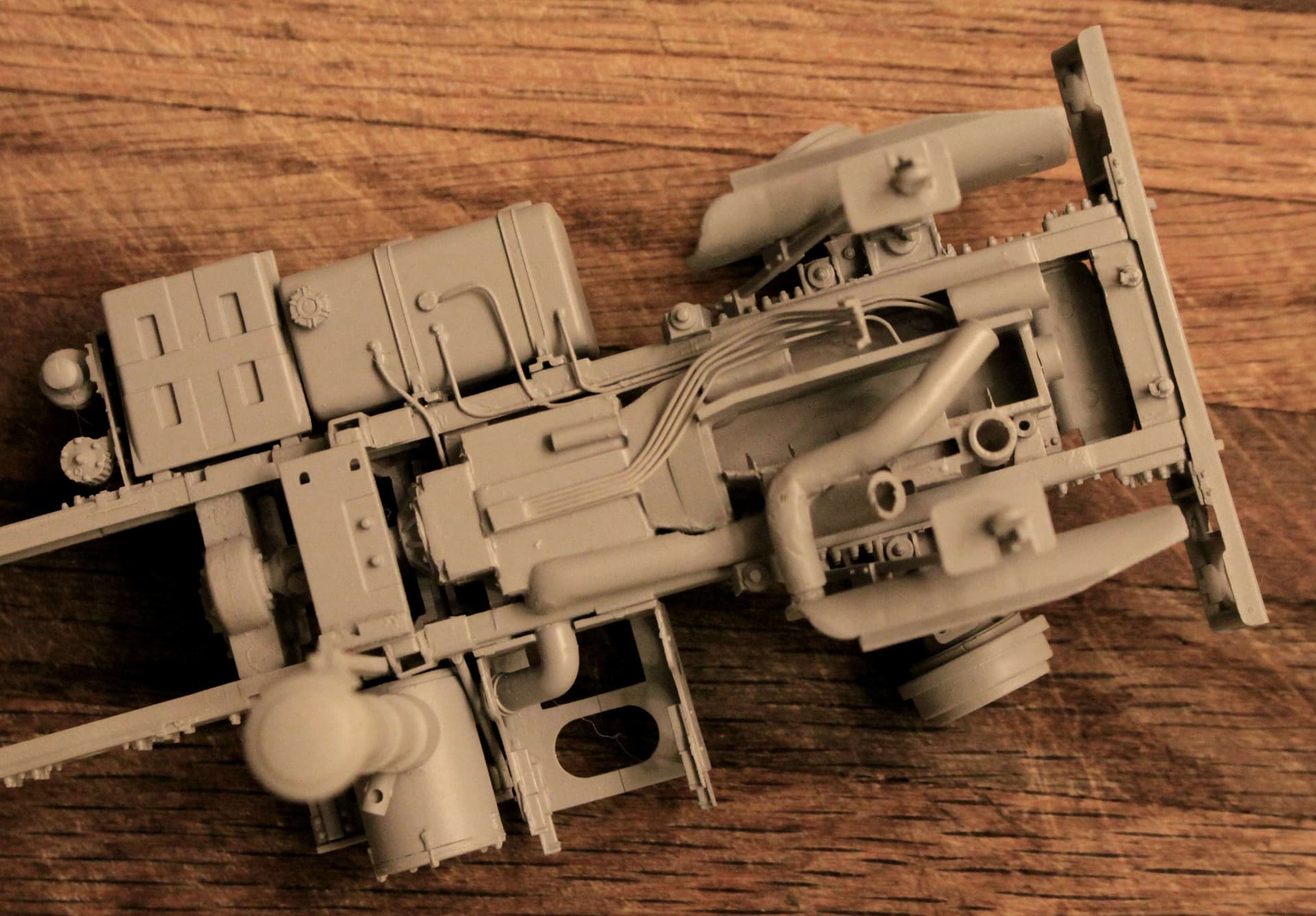
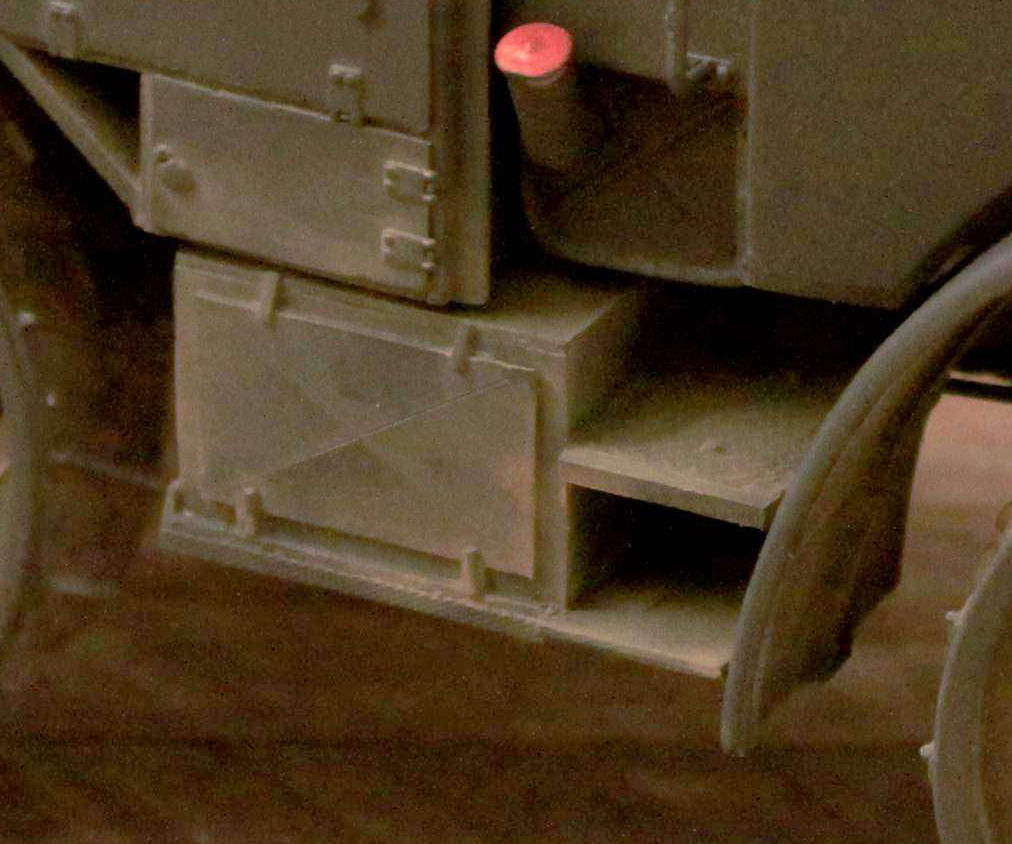
The transmission top, wiring and fuel line detail IS visible from both sides just above the cab steps and just under the cab.
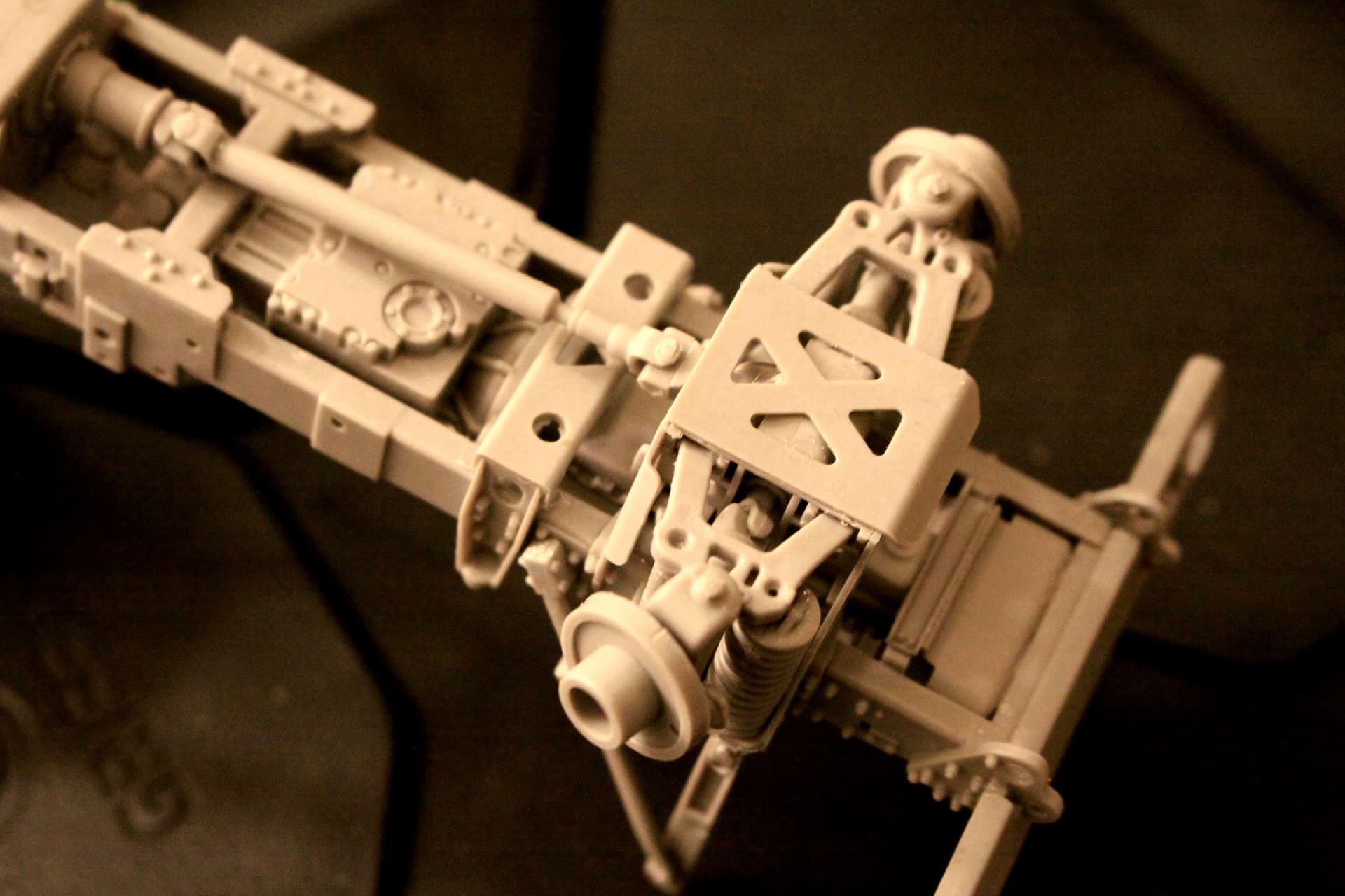
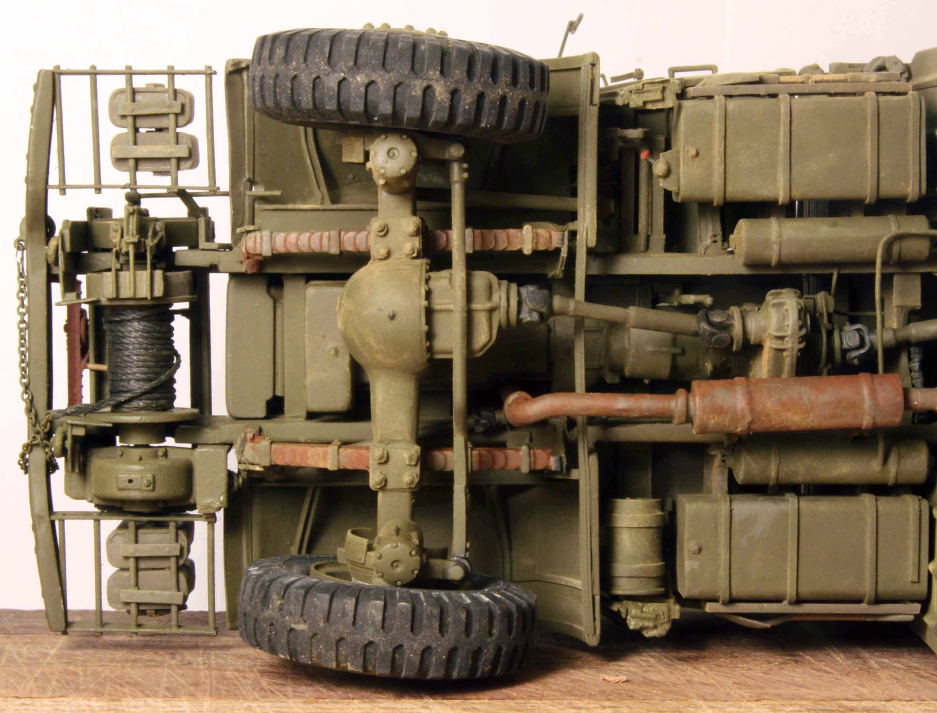
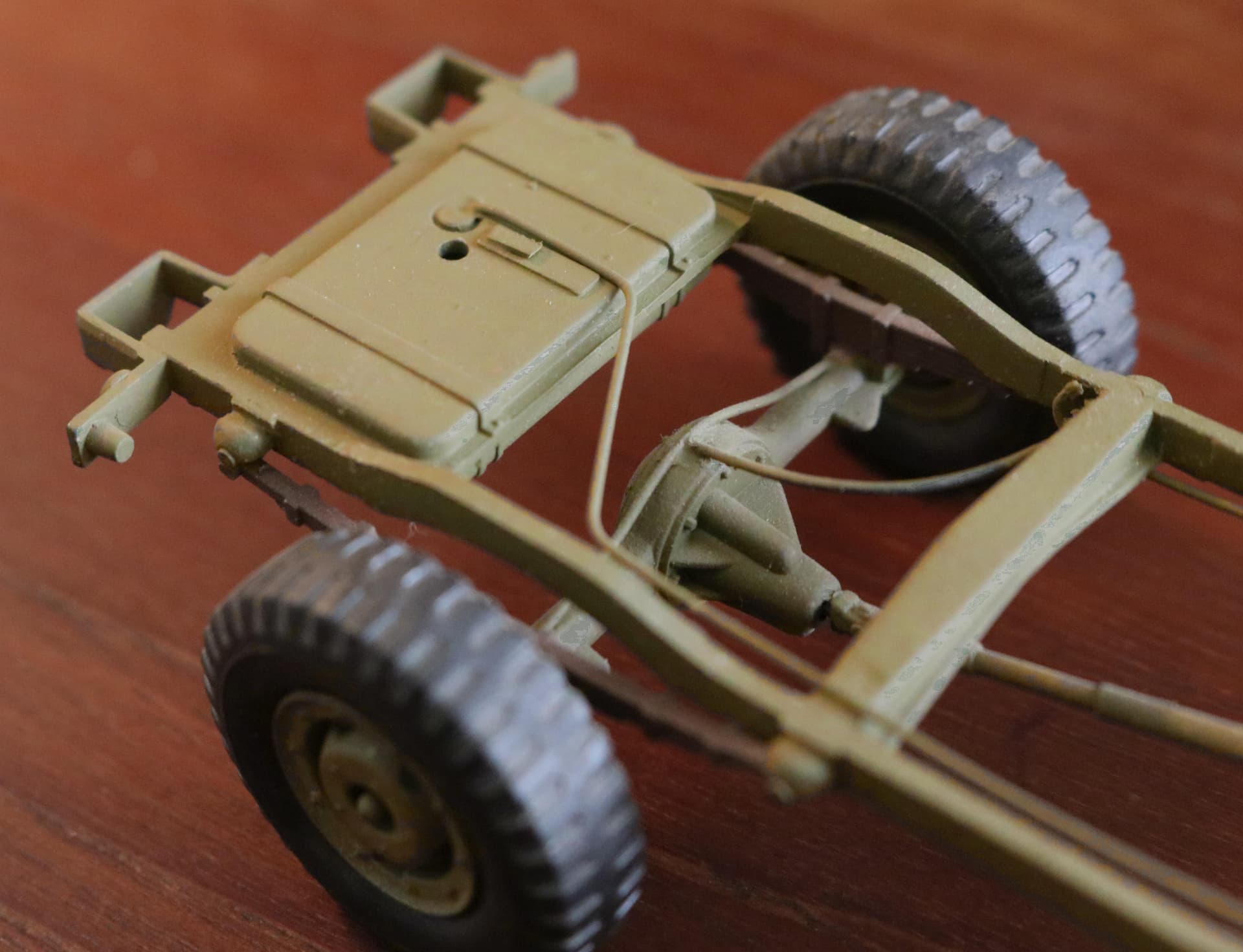
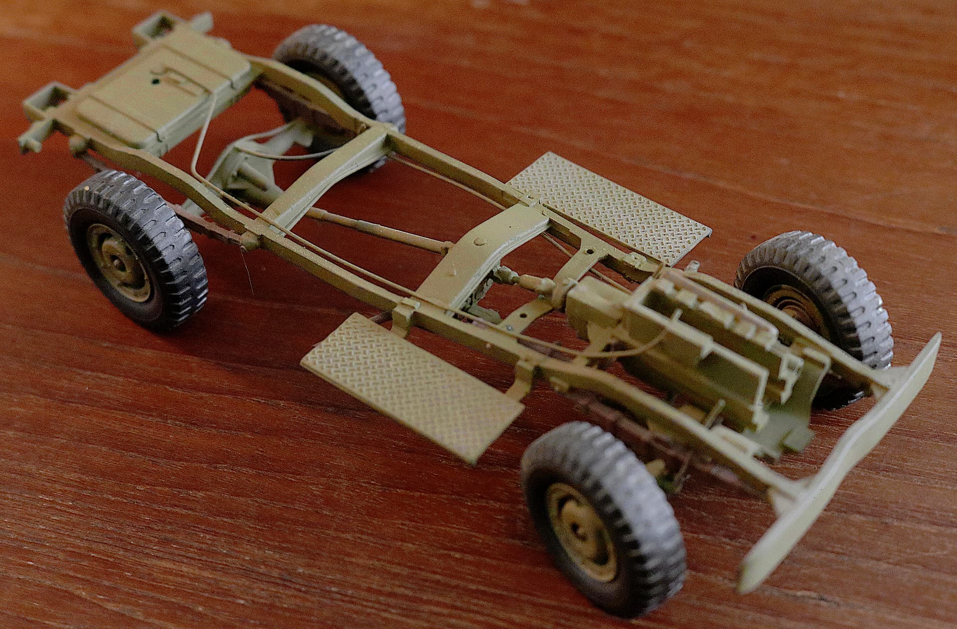
Here is a much more simplified engine treatment on the White/Corbett 666 Cargo Truck: -
After cutting out the flat pan I then added engine side panels, main crank pulley, generator and starter.

Oh, and I also canted the front wheels and added the front wheel brake lines and the fuel line coming out of that fuel filter. (Funny place to put an unprotected fuel line and filter don’t you think Mr. White ???)
Here is a much modified engine oil pan from a Tamiya Dragon Wagon doing duty with my big Mack NO Artillery Tractor.
The Mack had a HUGE oil pan/oil sump descending in front of the front axle giving the Hercules greater oil capacity and greater engine cooling.
6 Likes
You’ll get no argument from me… Both. ![]()
![]()
Nice attention to detail!
—mike
1 Like
And now for the venerable old, Old, OLD Italeri Dodge Ambulance:
My very first engine profile rebuild - EVER!
This one isn’t just years old, it is DECADES OLD!
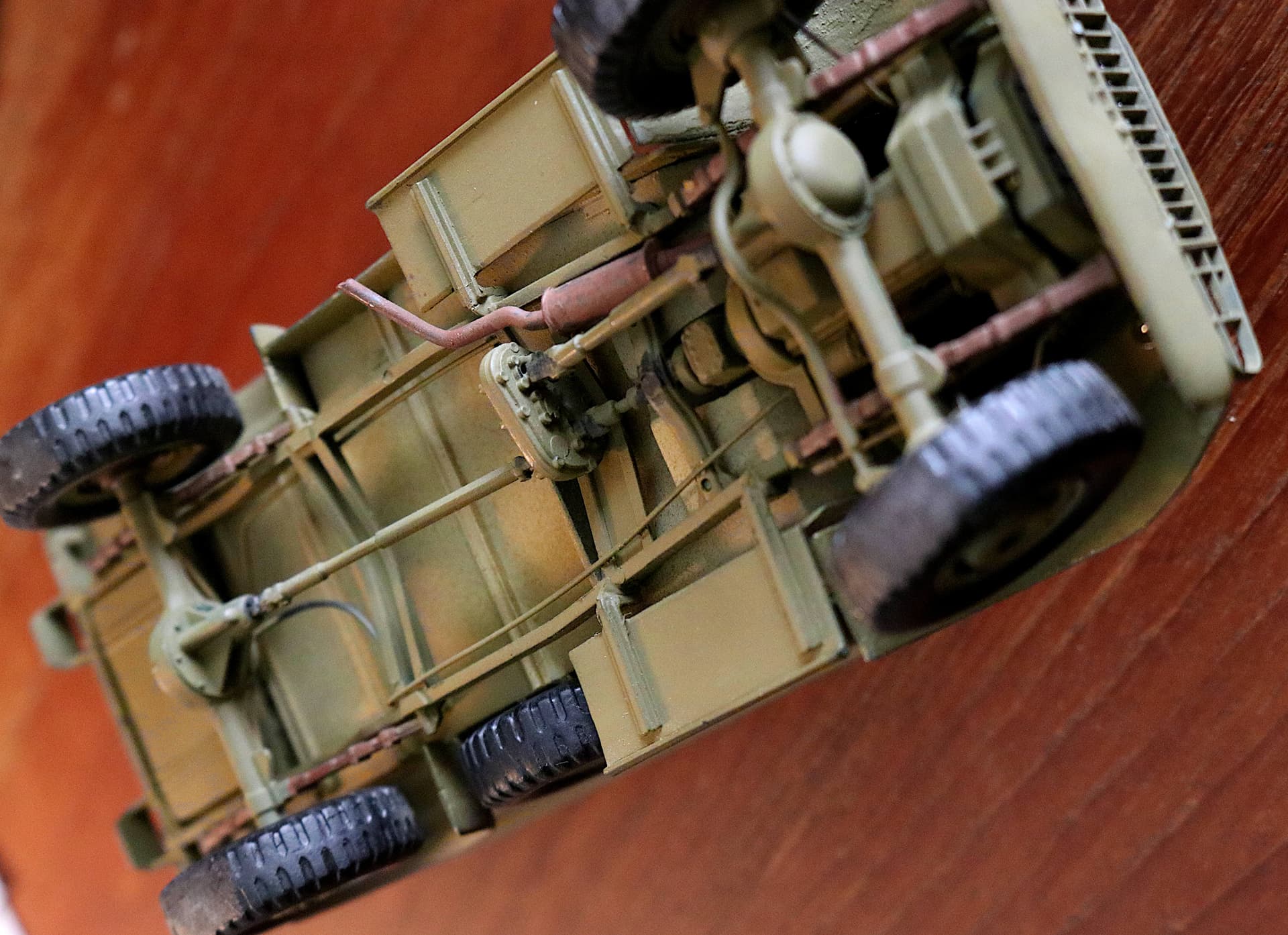
This one is nearly “Museum Clean” underneath!
Darn, should’a added the tail light wiring as well!
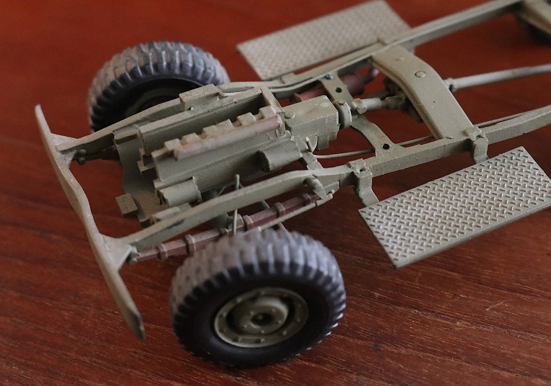
Followed just a few months later by the Italeri Weapons Carrier. Also with a profile engine:
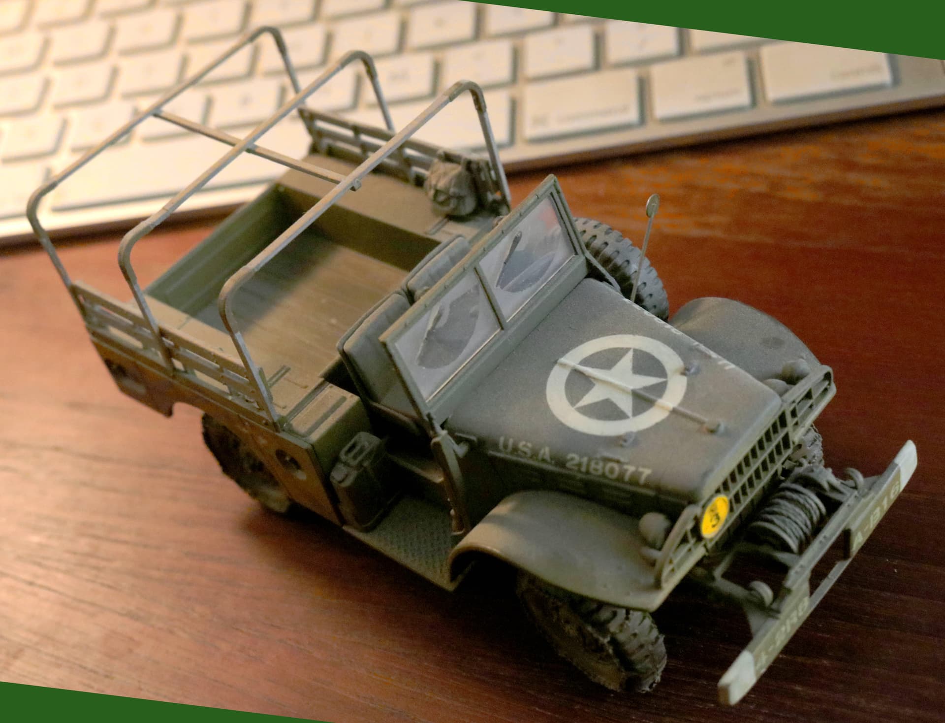
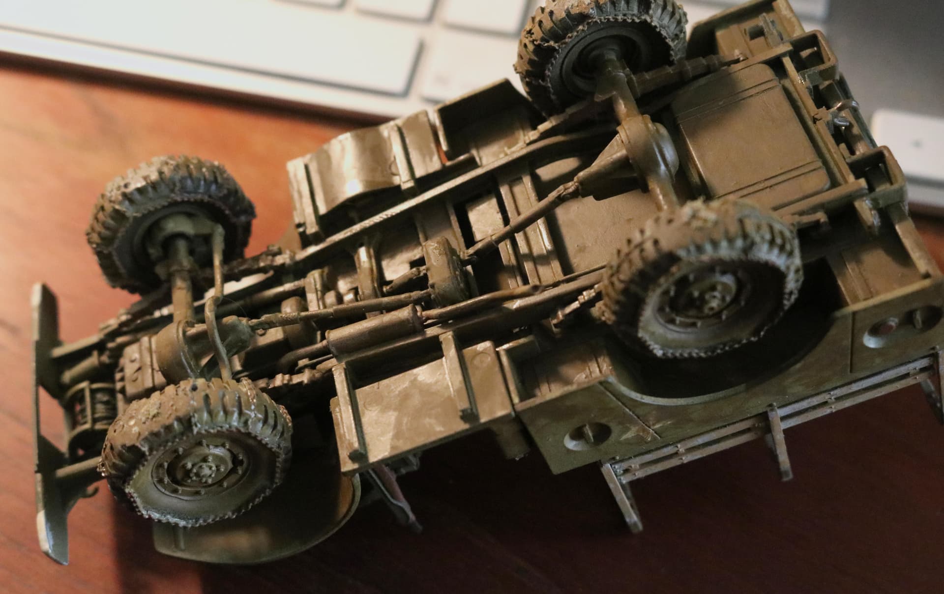
This ones’ got’a little mud on the tires! - (Therefore the wet look underneath.)*
4 Likes
As I was just saying . . . .
That Mk23 Marine Corps Cargo Truck Could Sure Use a Resin, or Plastic or 3D Printed engine!

That one piece fiberglass hood, (cover, bonnet, whatever you wish to call it!) though not currently hinged would be easily posed in the open position if we only had an engine to show off. (If someone is already offering it I certainly missed it!)
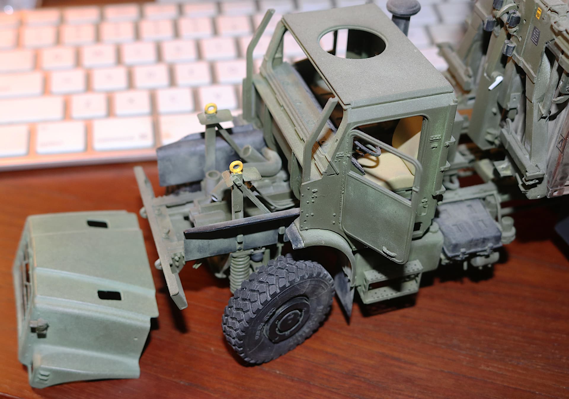
Gino, Stick, Michael, have you seen anything of an engine for this one yet???
3 Likes
Was ist los, mein Herr Inspektor?
Wo ist die Bombe?
1 Like
I haven’t seen a resin/AM engine for it. However, It uses a CAT C12 engine. If you can find another kit that has it, you can get one and put it in. I have plans to do the same for an M1083 5ton FMTV truck. It uses a CAT C7 engine that is also used in the M1240A1 MRAP by Rye Field. The engine, tranny, and under hood parts are all on one sprue. I ordered the sprue from a guy on eBay and now have a complete engine/tranny and a few other parts to add to my M1083 FMTV.
There is a 3D printed Cummins engine on eBay. It is listed as 1/32, but I contacted the designer/seller and he could easily scale it to 1/35. It isn’t the exact engine, but may be close enough. It looks really good too. And no, he doesn’t have any CAT C12 engine plans.

Lots of 3D car engines on eBay, but only the above truck engine.
Very good suggestion however after just a very quick Google search it appears that only the MTVR uses the CAT C-12.
In all honestly I am already invested in my two Marine trucks both using my profile engine. I have no future plans to build another MVTR so my question here is for the benefit of others and not myself.
1 Like
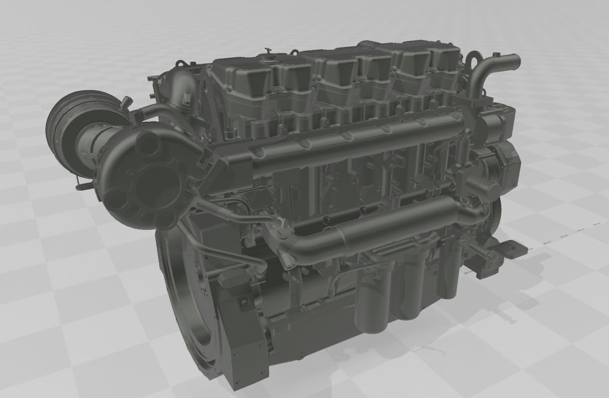
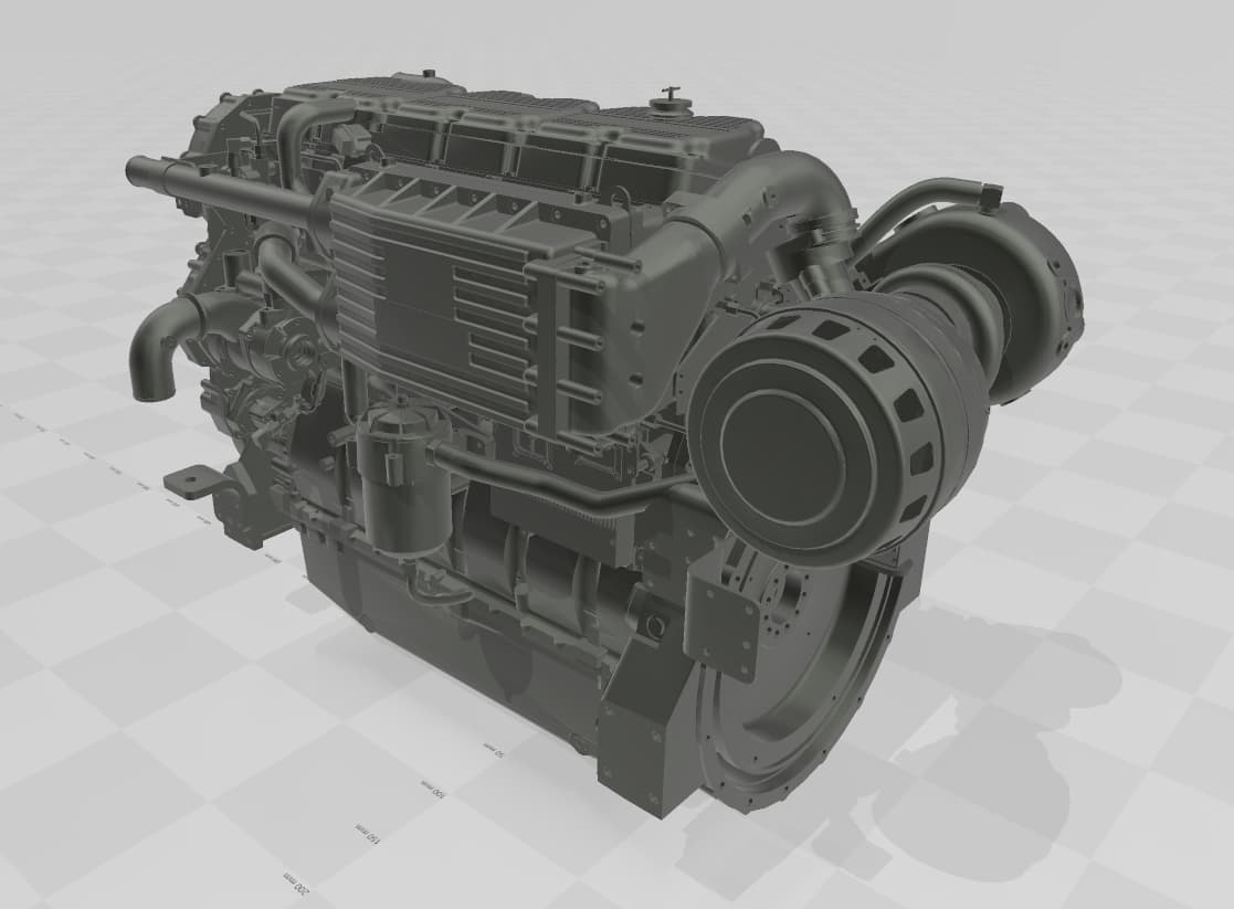
So I obtained several complex CADs of Caterpillar engines from Solidworks CAD library. Not sure how useful these are for 3D printing and 1/35 modeling but I have them:
CAT C-7 engine:
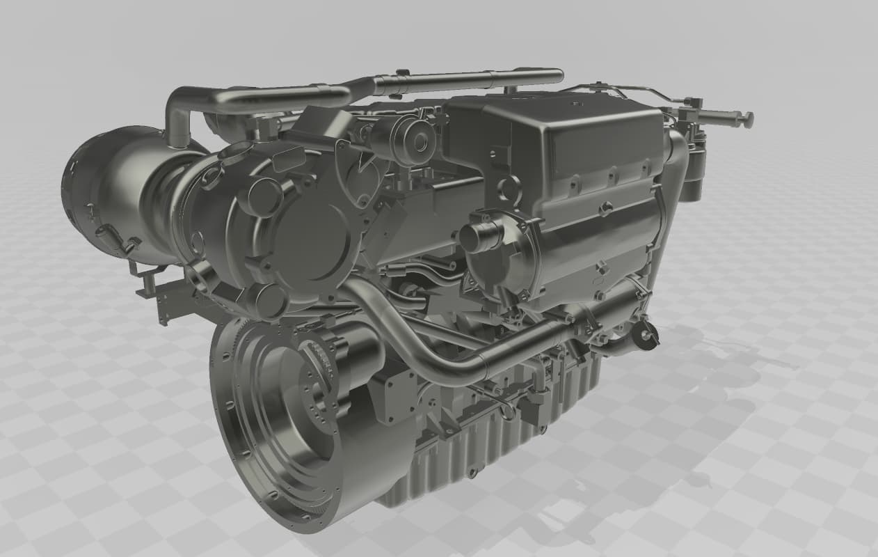
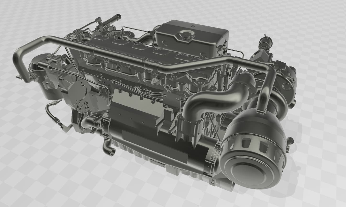
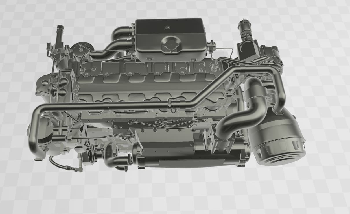
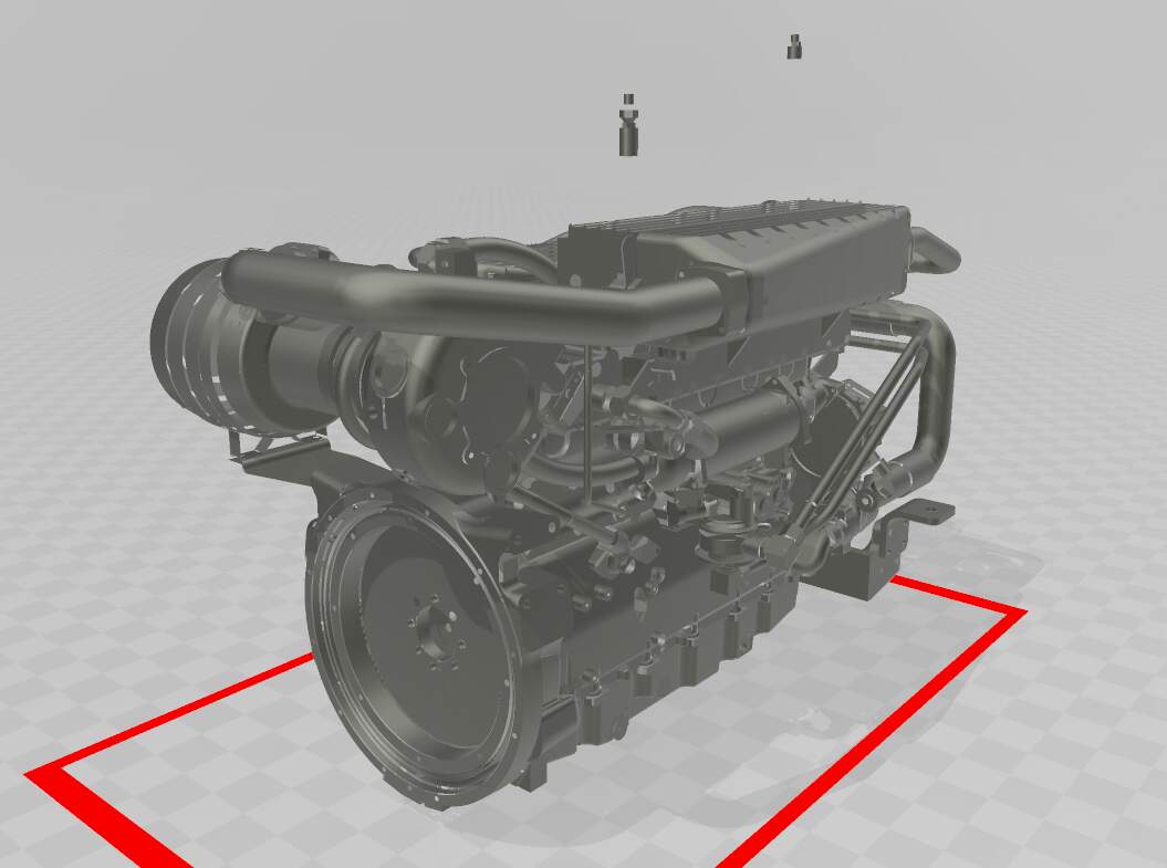
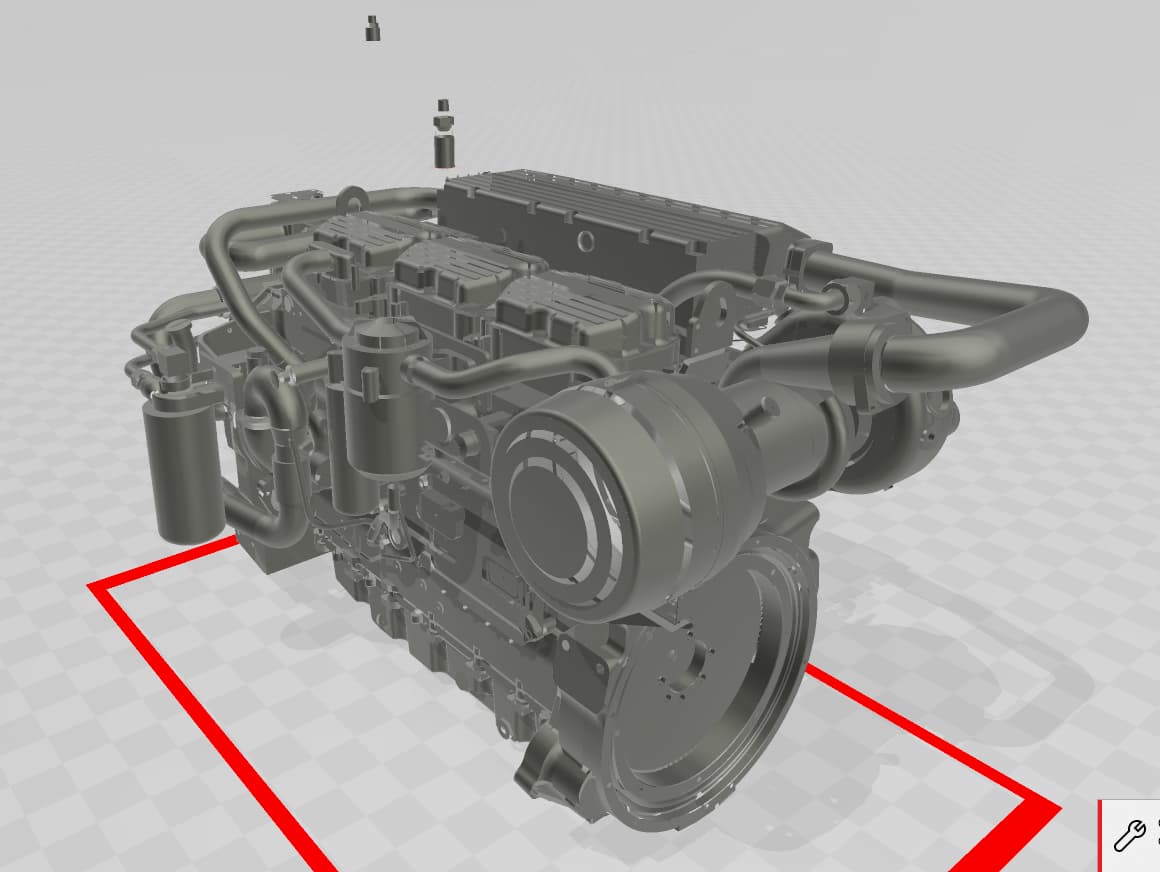
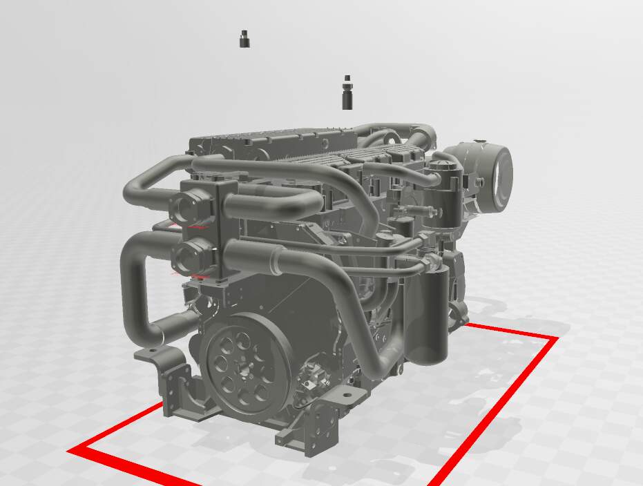
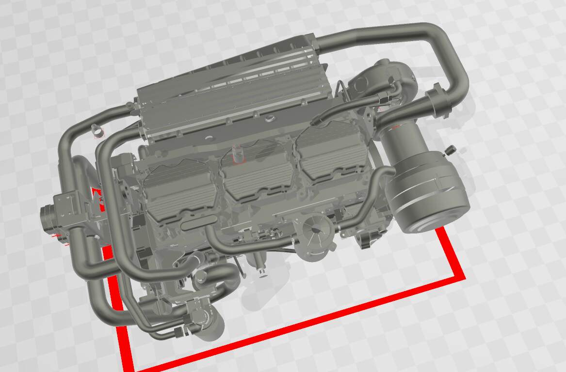
CAT C-12 engine:
CAT C-18 engine:
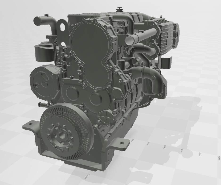

I don’t know enough details so I’d need help to accurately revise them for 1/35 3D printing.
Kind regards,
James
The turbo, plumbing and intercooler arrangement on your C-12 is set up for installation in a long narrow application such as a standby gererator. Where as the C-12 installed in the MTVR is in a wide, short nosed format.
Im sure the basic CAD for the engine itself would be fine as a starting point but we (you) would need some really great reference to get the accessory and plumbing layout correct.
On the Mk23 the C-12 turbo is mounted on the right front side of the engine and the intercooler seems to be mounted up front on the right side of the radiator with all the necessary associated plumbing.
Then there seems to be some sort of rather unique triangular mounting bracket that attaches the top of the radiator to the front top of the engine with the radiator houses routed around this.