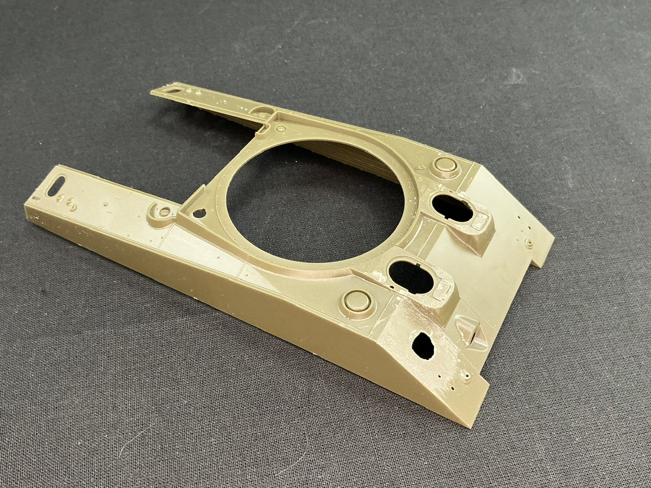
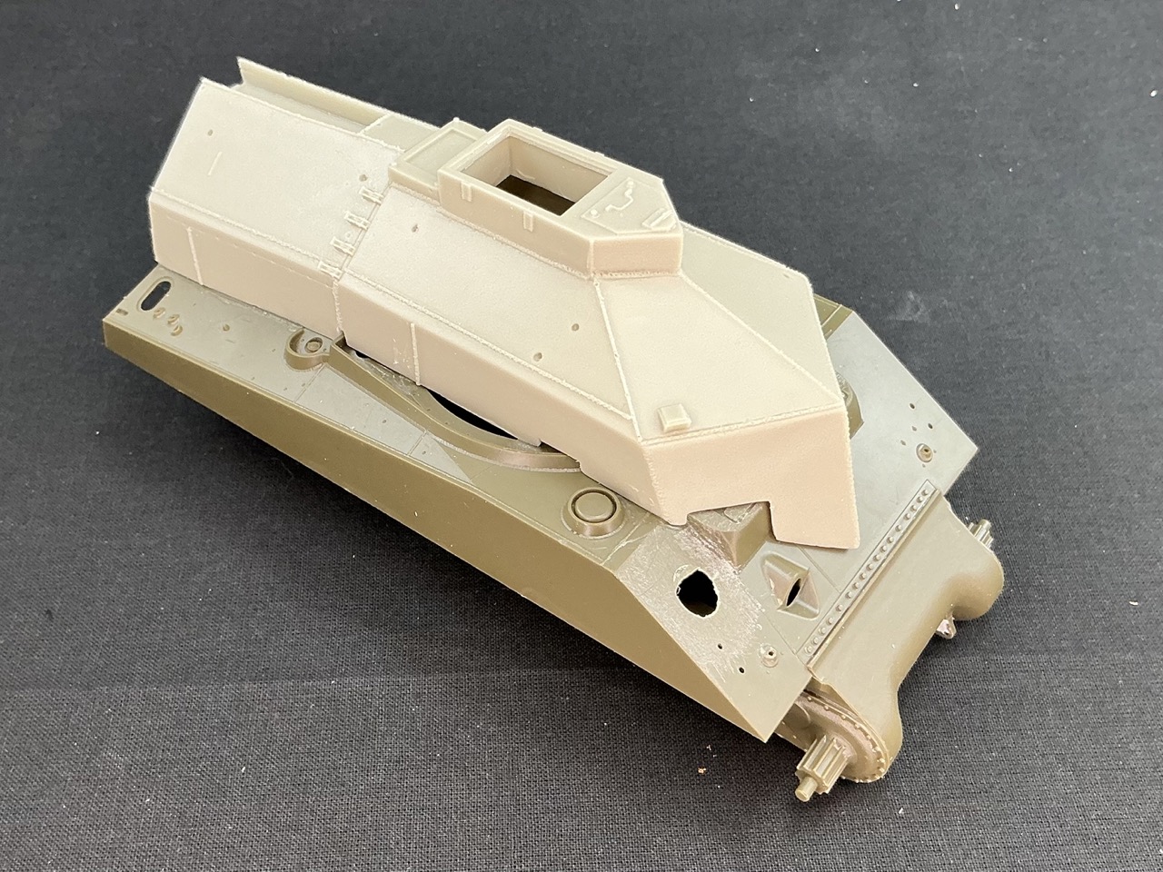
For a D-Day group build on another forum, I decided to pull the Resicast BARV conversion out of the stash and mate it up with an Asuka Sherman III. You know you have AMS when the first thing you do on the first part you remove from the sprue, is cut bits away:
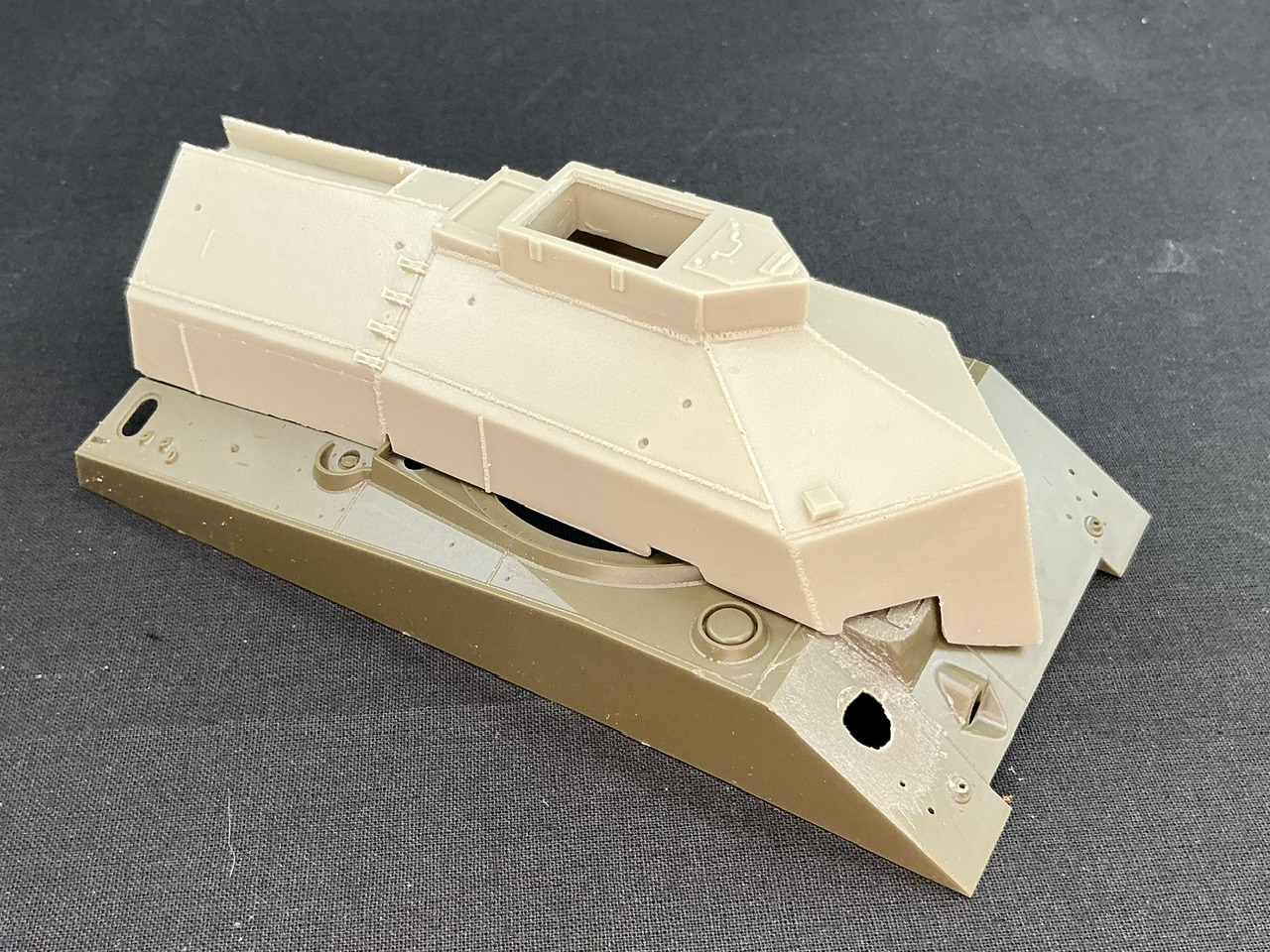
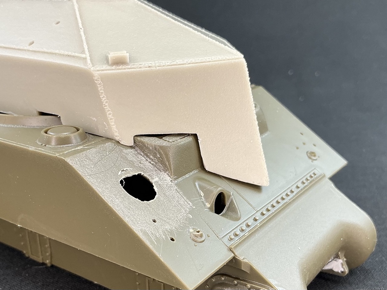
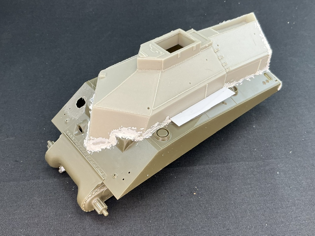
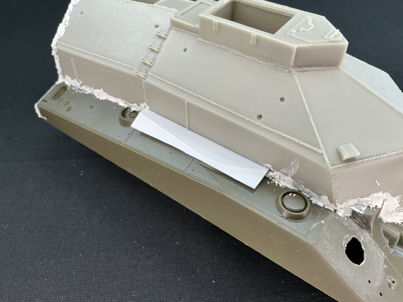
That is, I built the transmission housing (the nose) and glued it to the lower hull, then added the upper hull. The two pieces of plastic strip at the rear are because I’ve also been working on the resin superstructure to get it to fit, and it wants to skew to the left at the rear a little. The strips are there to hopefully guide it into its proper position, but I won’t know until the glue has fully dried, tomorrow.
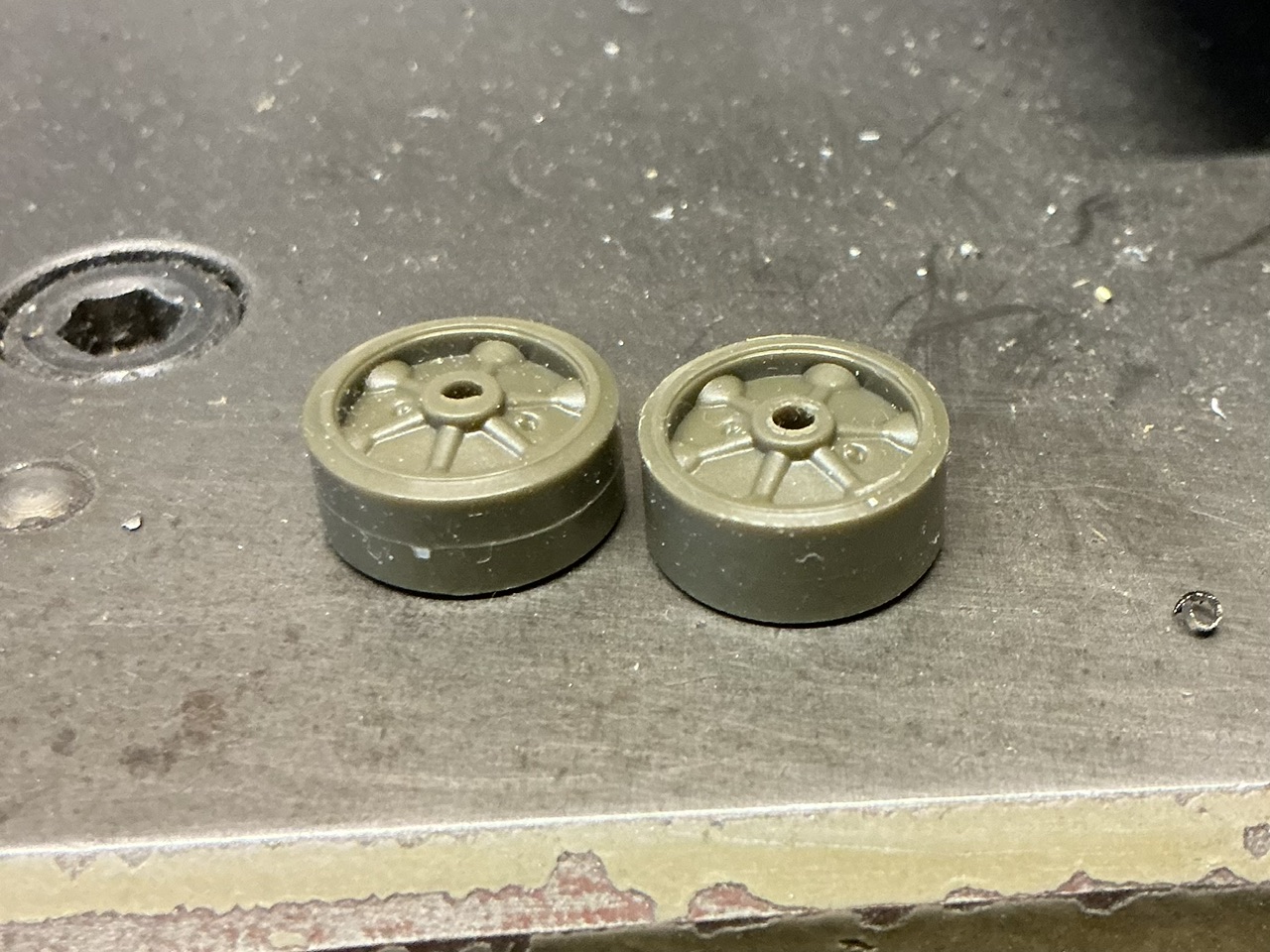
So I went on to the wheels. They have a seam down the middle, which is far too big to represent the one that was there on the real thing, and in any case that would wear down soon enough on the real tank. You can scrape it off, as I’ve done lots of times, but I decided for this one to take the luxury option:
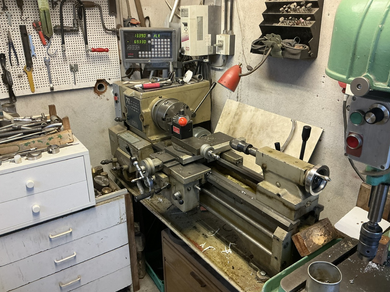
My father’s shed, with his lathe. To put a wheel into it, I put a long M2 screw through the hole in the wheel, with a nut on the other side, tightened using a screwdriver and pliers because hand-tight is not tight enough.
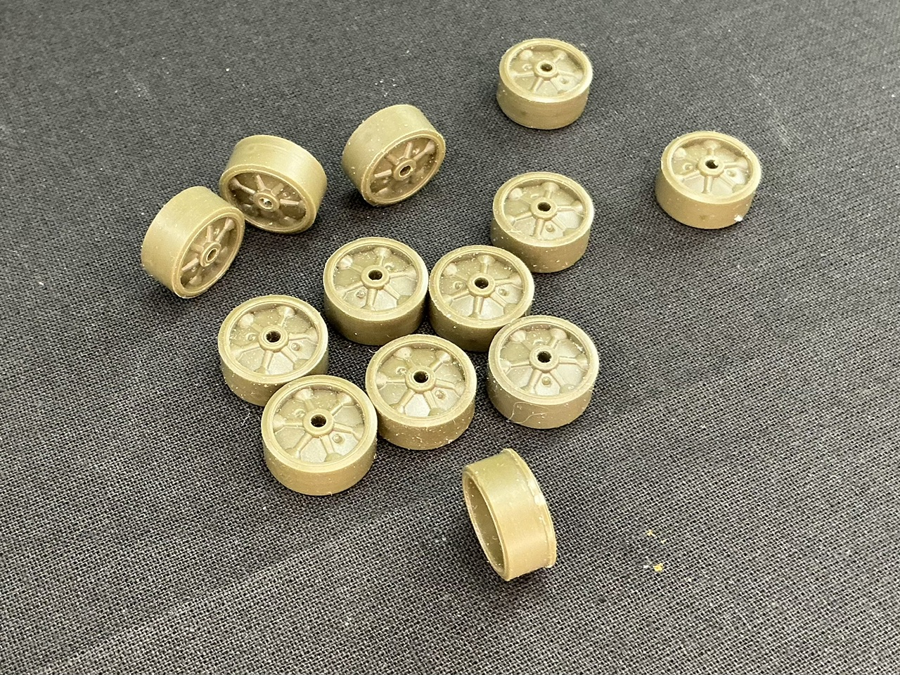
Once I found how far to turn the first wheel down (see the upper left number on the electronic display gizmo in the first lathe photo) I could just do all the others in one go rather than layer by layer. However, sometimes the chisel would bite into the wheel and stop it, requiring me to remove it, tighten the nut, and try again. Here’s the end result:
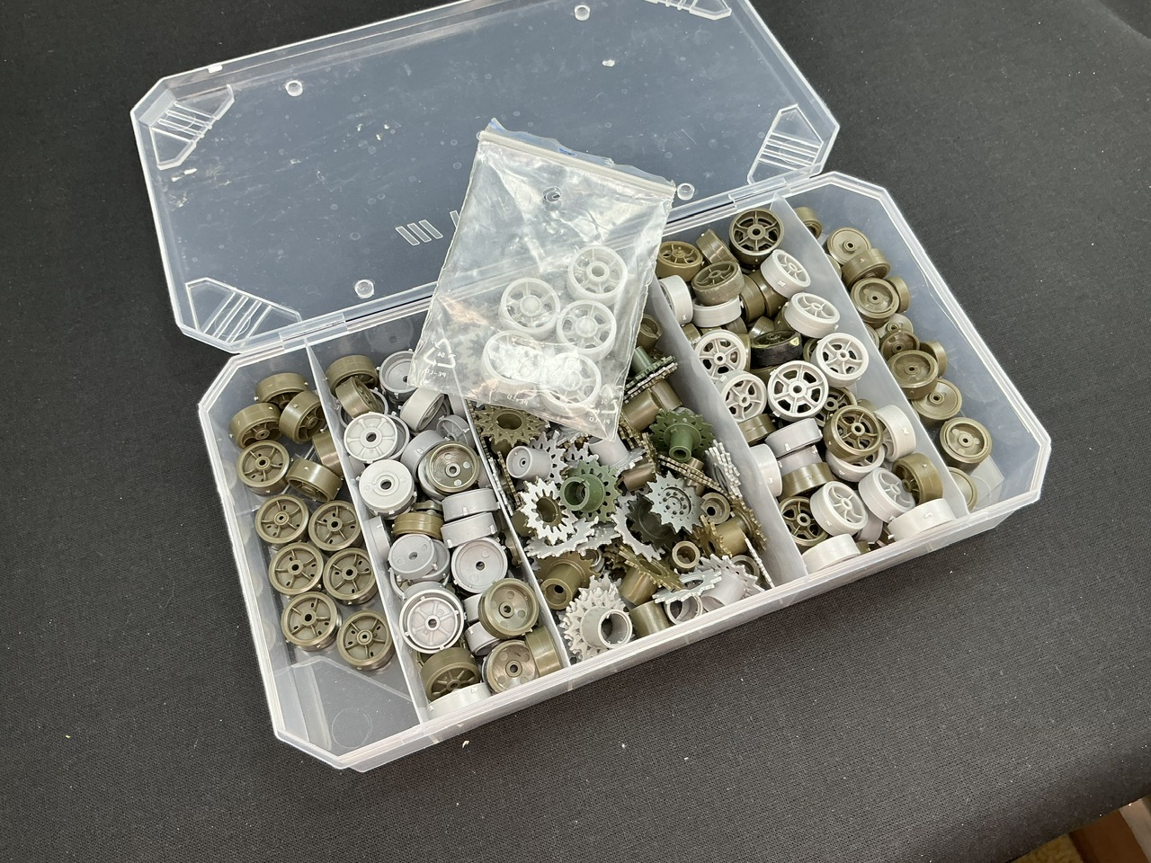
Notice the one in the front, with the rim on one side. That one did not want to cooperate, so I eventually gave up and grabbed a thirteenth wheel from my spares box. I mean, it’s not like I’m wanting for them:
With which I mostly mean that it doesn’t have a pivot point at about a third of the way along from the back anymore. There is still a bg gap at the front:
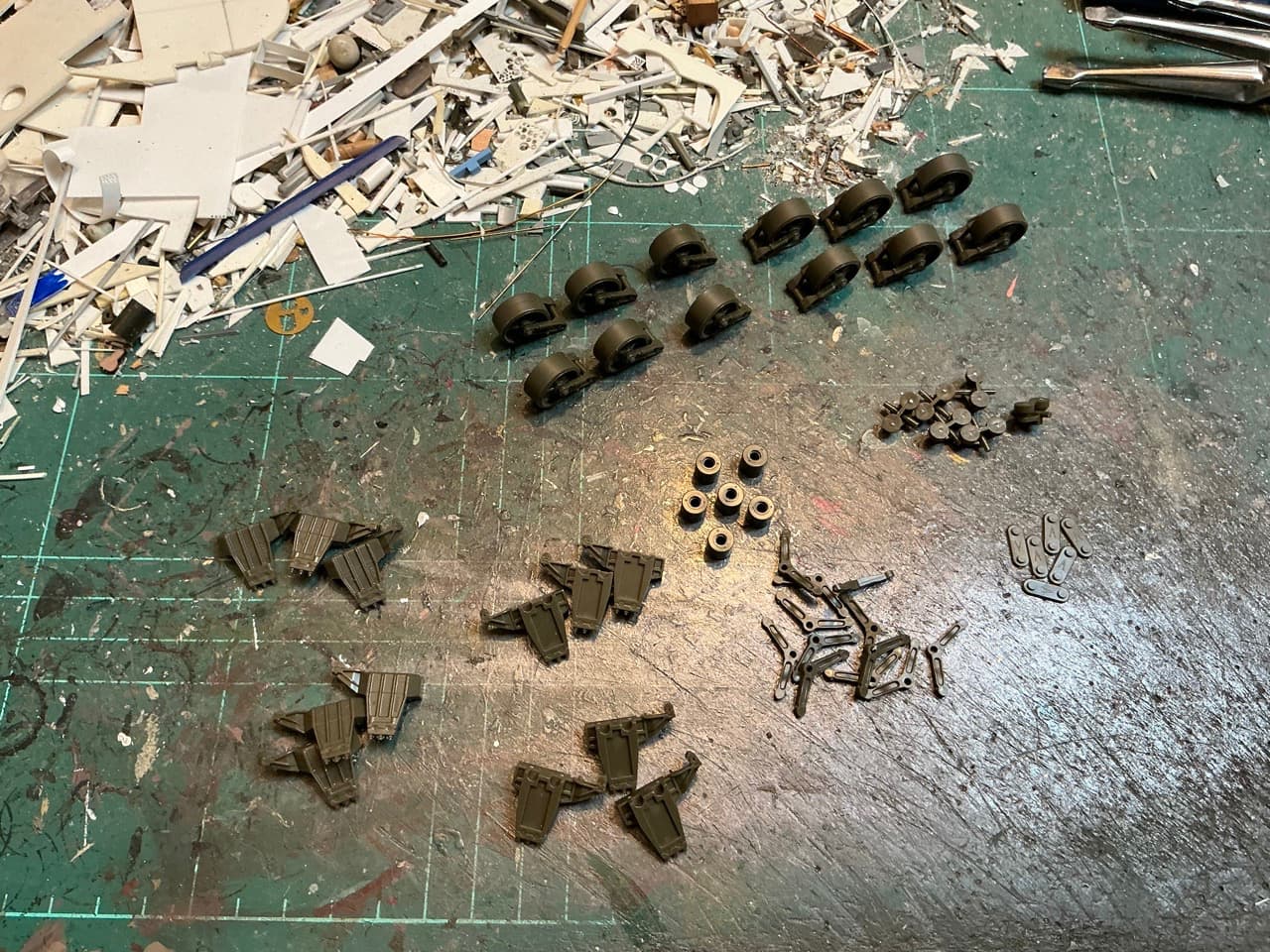
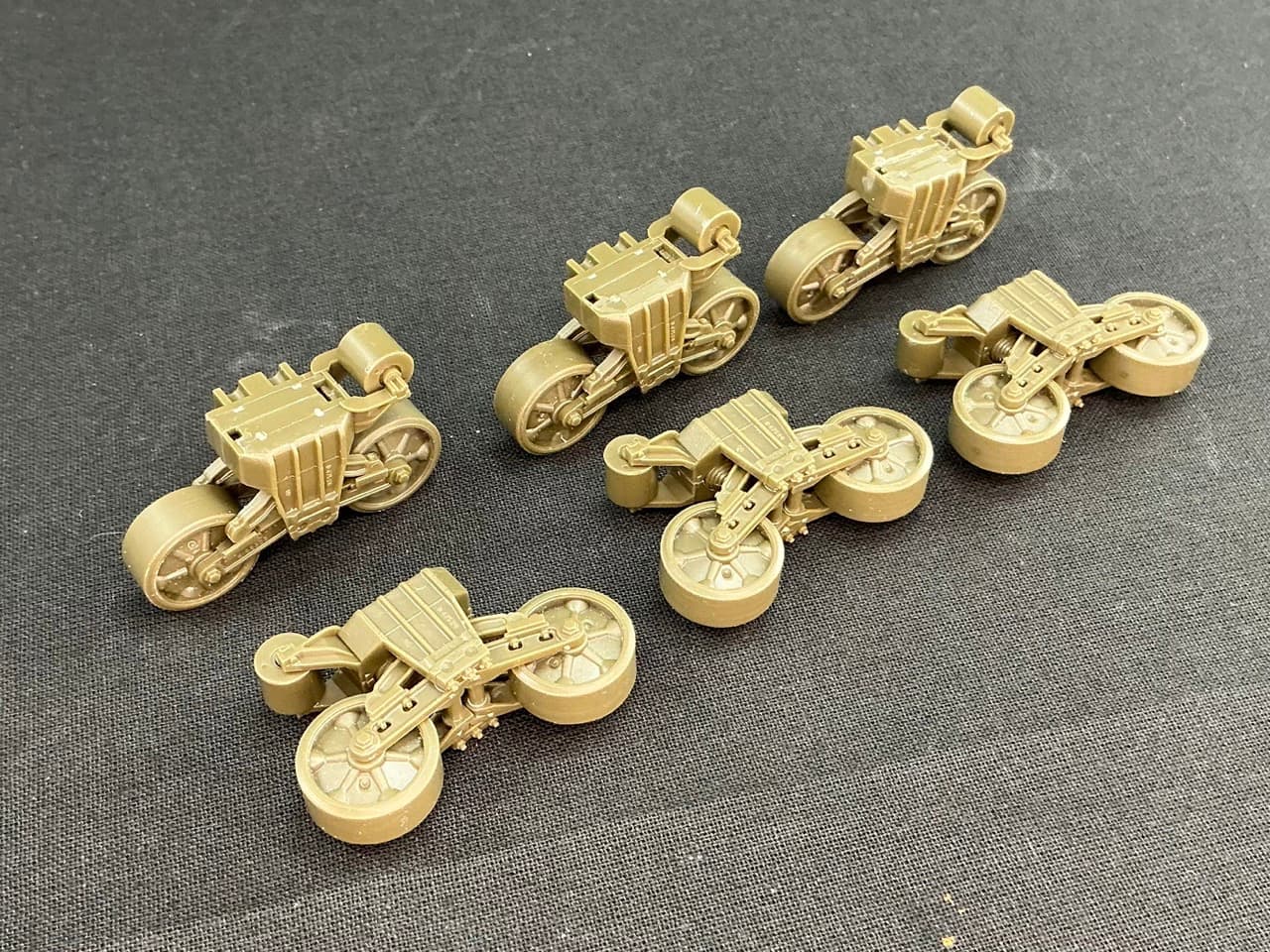
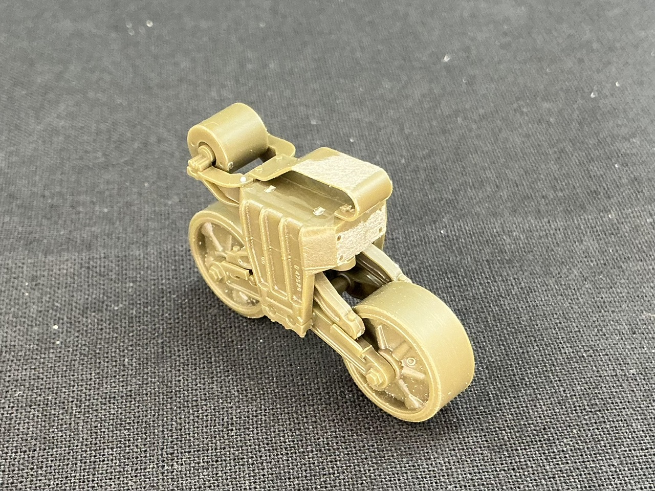
The wheels and suspension arms are already built (two parts per wheel, and an inner and an outer arm), and the rest is almost everything you need to build six bogies, Asuka style. The only part missing is the skid that goes on top. The bogies built:
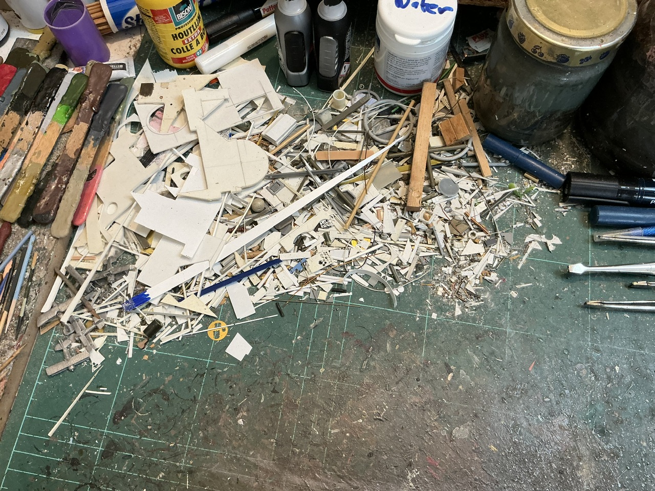
Jakko WHAT is that rubbish mound on the top left that looks like the town dump?! That’s in residence on your bench? How long did it take to grow that big? That gives me convulsions just looking at it. I’d be afraid of little bits of it sticking to and contaminating my current build. Sorry, I’m OCD and have a DSPIAE vacuum for my bench that I use every day.
Those are all offcuts of plastic card, model parts, bits of wire, interestingly shaped sections of sprue, and assorted other bits and bobs that aren’t actual kit parts. The whole reason that pile is there is so I can sort through it looking for a suitable piece when I need to detail, scratchbuild, etc. something small. I’m not going to cut a 5 × 3 mm rectangle from a whole sheet of plastic card if I can find a 10 × 6 mm triangle of leftover card that it will also come out of
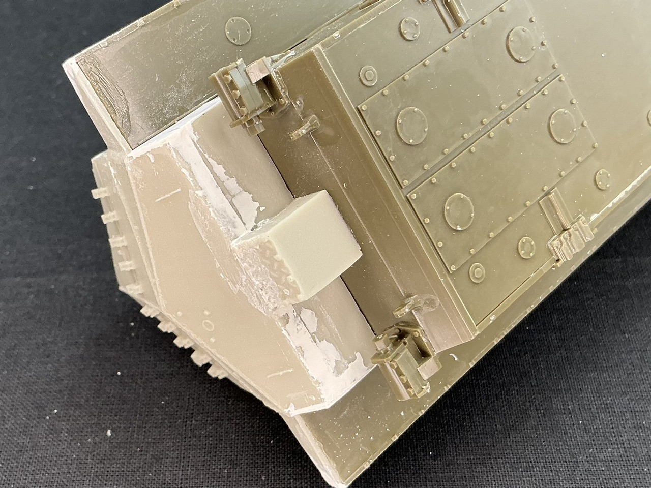
Basically, I filed the front face flat and drilled four holes into it, then added the skid on top and glued a bolt head (punched from card) next to it on the outboard side. There should also be one inboard, but once the track is on, you can hardly see that at all, so I’m saving myself half the work here.
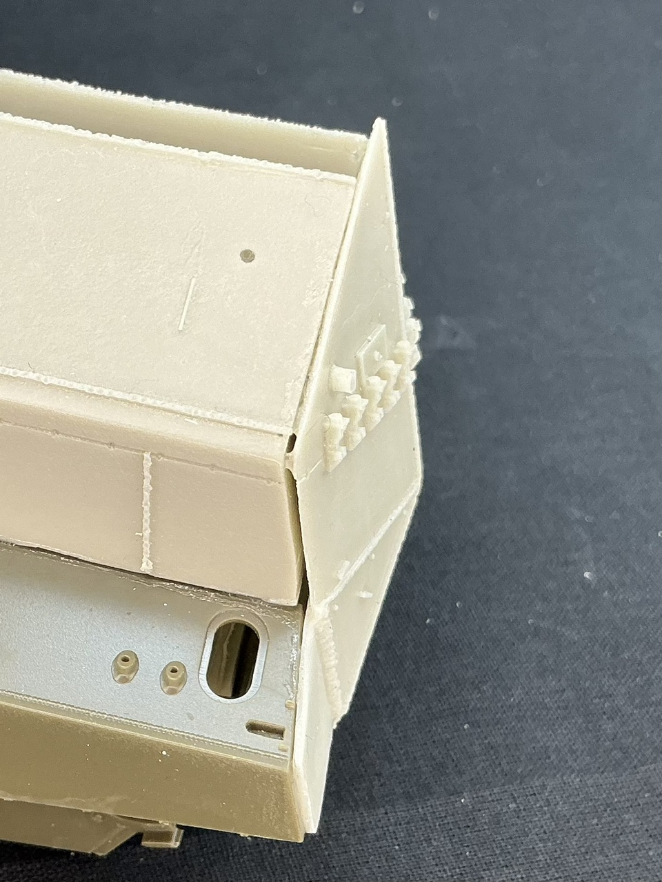
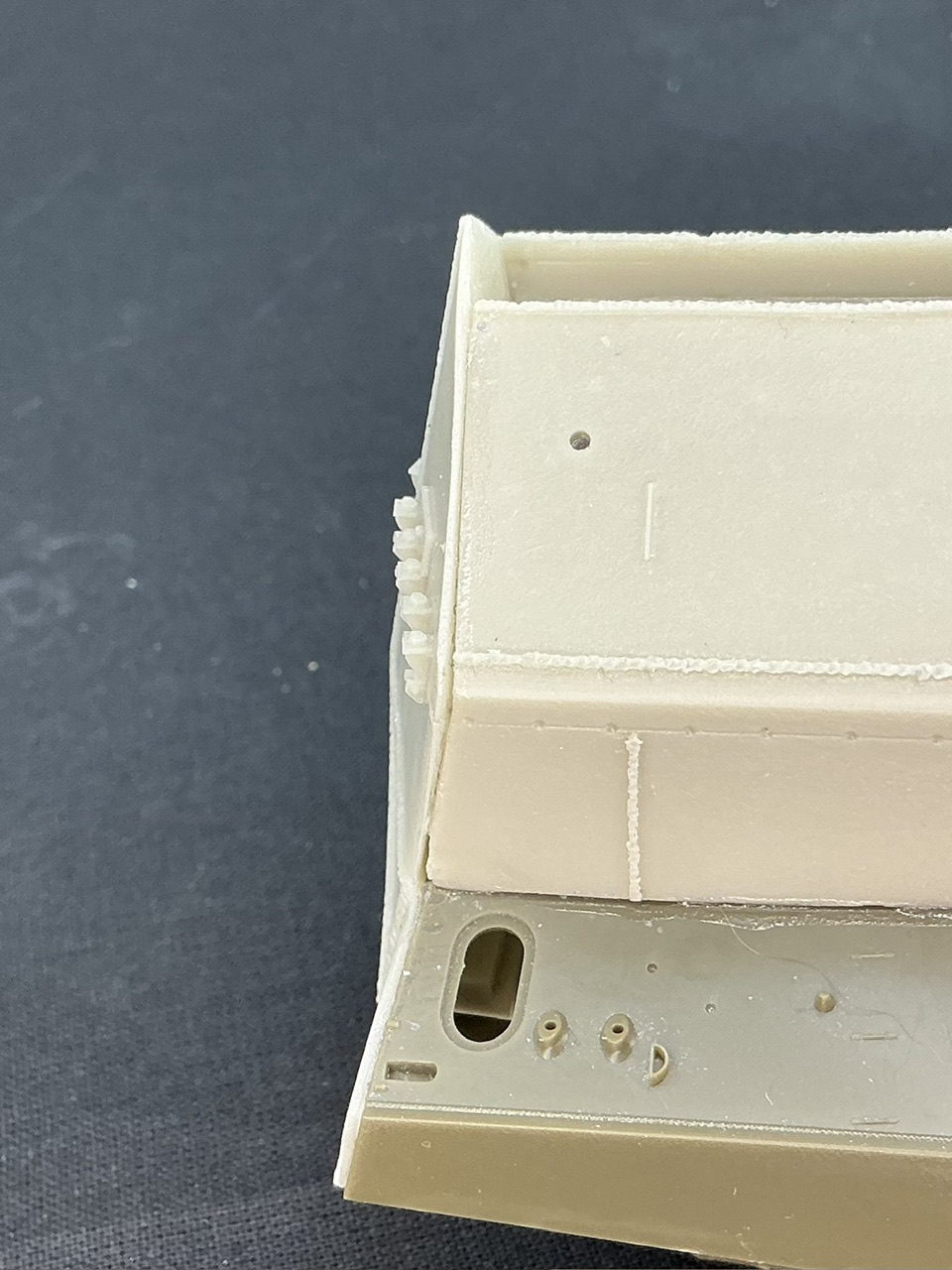
I also glued the back plate on, but it has large gaps, worse on the left than on the right:
This is why I did that now, BTW, before filling all the other gaps that the superstructure leaves There’s also a piece underneath that covers the exhausts on the real BARV:
As you can see, it also leaves big gaps but the instructions mention nothing about those at all, and I can’t find any parts that will cover them later on. I think I might just fit a piece of plastic card over the sides to close these.
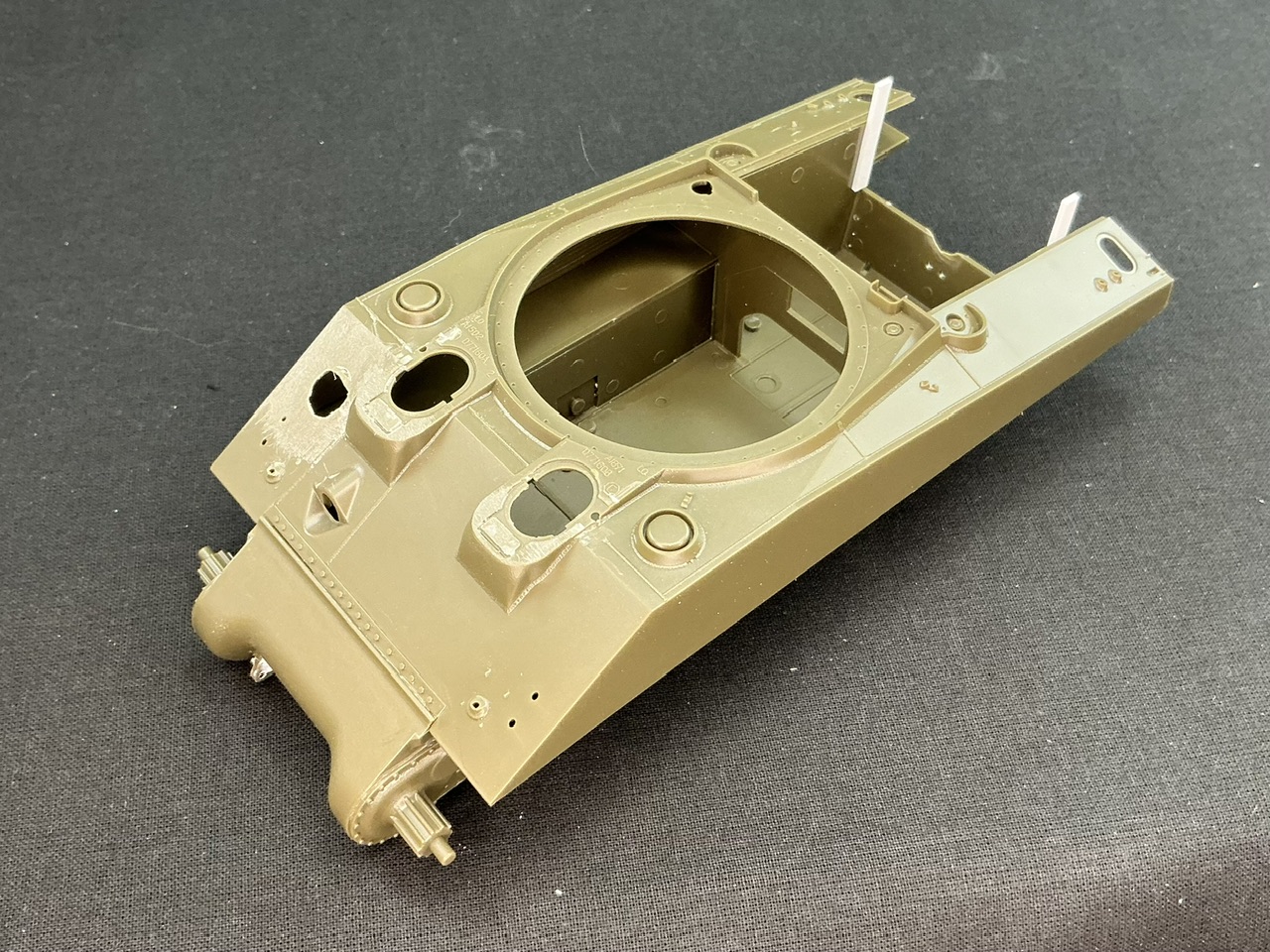
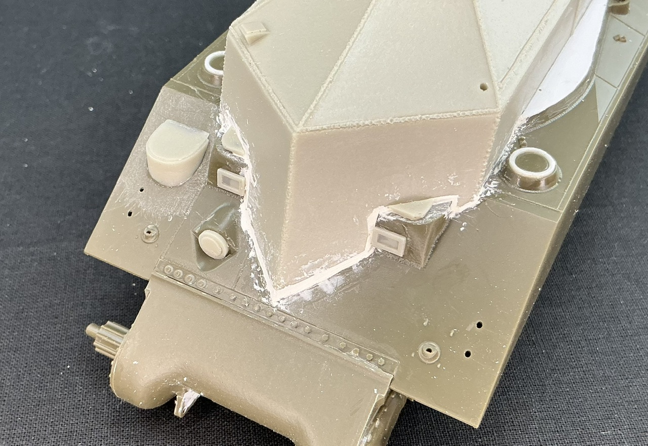
Resicast says to do this with epoxy putty, but I used car body filler from a tube, because it says it’s also suitable for polyester car bodies, so I hope that means it also sticks to the polyurethane resin of the conversion set’s parts. Resicast also says to fill the turret ring with epoxy putty, but I instead glued a bit of thin plastic card over the opening on each side, because on the real vehicle, there was a piece of sheet steel there, according to this walkaround of a real one. It’s intentionally oversize, so I can trim it to size when the glue and putty have dried — much easier than trying to make it to shape and size first and only then glueing it to the model.
The hatch on top of the superstructure — it’s the only crew hatch on the vehicle Inside, there was a plate that covered most of the turret ring opening. There is a thread on Maple Leaf Up that has interior photos.
Those, incidentally, seem to show a small mistake in Resicast’s kit. That has a floor there too, but straight (no zig-zag on the right-hand side) and with a gap to left and right, rather than on the right only. I didn’t fit the floor at all, though, as I think I’ll have the hatch closed. Or perhaps with a crewman sitting in it.
This is great work! I love the fact that despite the roomy interior, the driver still has to squeeze himself through the narrow “small hatch” hull opening!
I’ve had plans for some years now to scratch the wrecked BARV parked outside the Tank Museum at Bovington in its “as found” condition - that’s when I first saw the Maple Leaf Up interior shots…
I’m both organised and chaotic at the same time. Things all have their place, where I expect and want them to be, but it’s never truly neatly ordered. My main tools are in a small pile to the right of the cutting mat you can see in the photo, for example, but those tools all need to lie there lengthwise, not just in a random jumble.
Thanks
I’m not sure of that. There is room on the right-hand side to go into the hull, so the driver could crawl between the floor and the prop shaft housing to get into his seat. Maybe different drivers used either way?
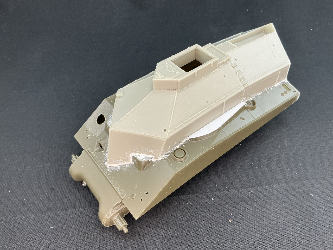
Anyway, first job after the putty dried was to trim the plastic card. This was a lot easier than expected when I realised that by pushing it down firmly, the shape of the splash guard underneath would become clear:
By wiggling it up and down some more, material fatigue even cracked it along part of that white line, and then some careful work with a sharp knife did the rest, followed by scraping it down to tidy up the edge.
Next, I used straight and curved knife blades to scrape down all of the filler:
The shape is so complex that filing is almost impossible for most of the model, and sandpaper will also be tricky to use. I did find out very quickly that “for metal and polyester”, as the tube of putty says, does not equate to “for polyurethane resin” because it just chipped off the resin parts. That, of course, is useful at this point, because it meant a lot less scraping there than on the plastic bits, to which the putty does adhere well. Once done, I had to add more filler in some areas, especially the nose, where shrinkage had caused it to form a depression even though I had trowelled it on pretty thick. Now I’m kind of waiting for that to dry.
I don’t remember what kit the Resicast conversion was for (if none). A friend of mine tackled it ages ago and I can’t recollect. Anyway you are of the fixer upper breed! Why should it be easy?
I always say last but it doesn’t work in the end.
I’ll be looking your progress!
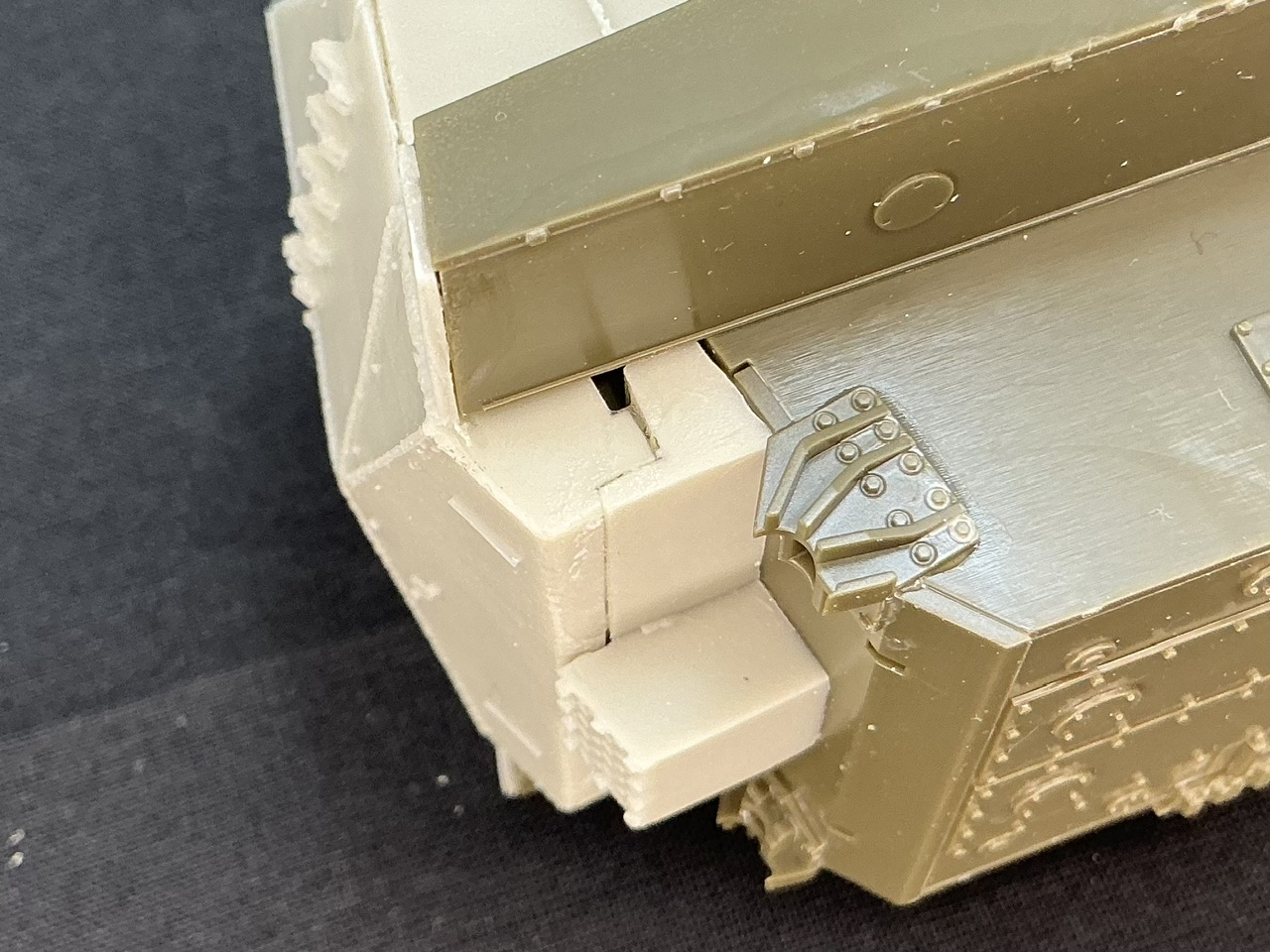
At the back, I glued thin plastic card to the sides to cover the holes, trimmed it to size when the glue was dry, filled the gaps that remained with the same car filler, and filed and scraped it flat when that had dried:
Most of these need weld beads added around them, as does the whole superstructure, but I’m still debating how to best make those.
Resicast seems to not have noticed that on the real thing, the ventilators on the hull had a flat ring welded over the opening to waterproof them. I made this by sawing two thin rings from 7.1 mm plastic tube and glueing them into the tops of the ventilators. That the plastic was softened by the glue helped a lot in getting them in.
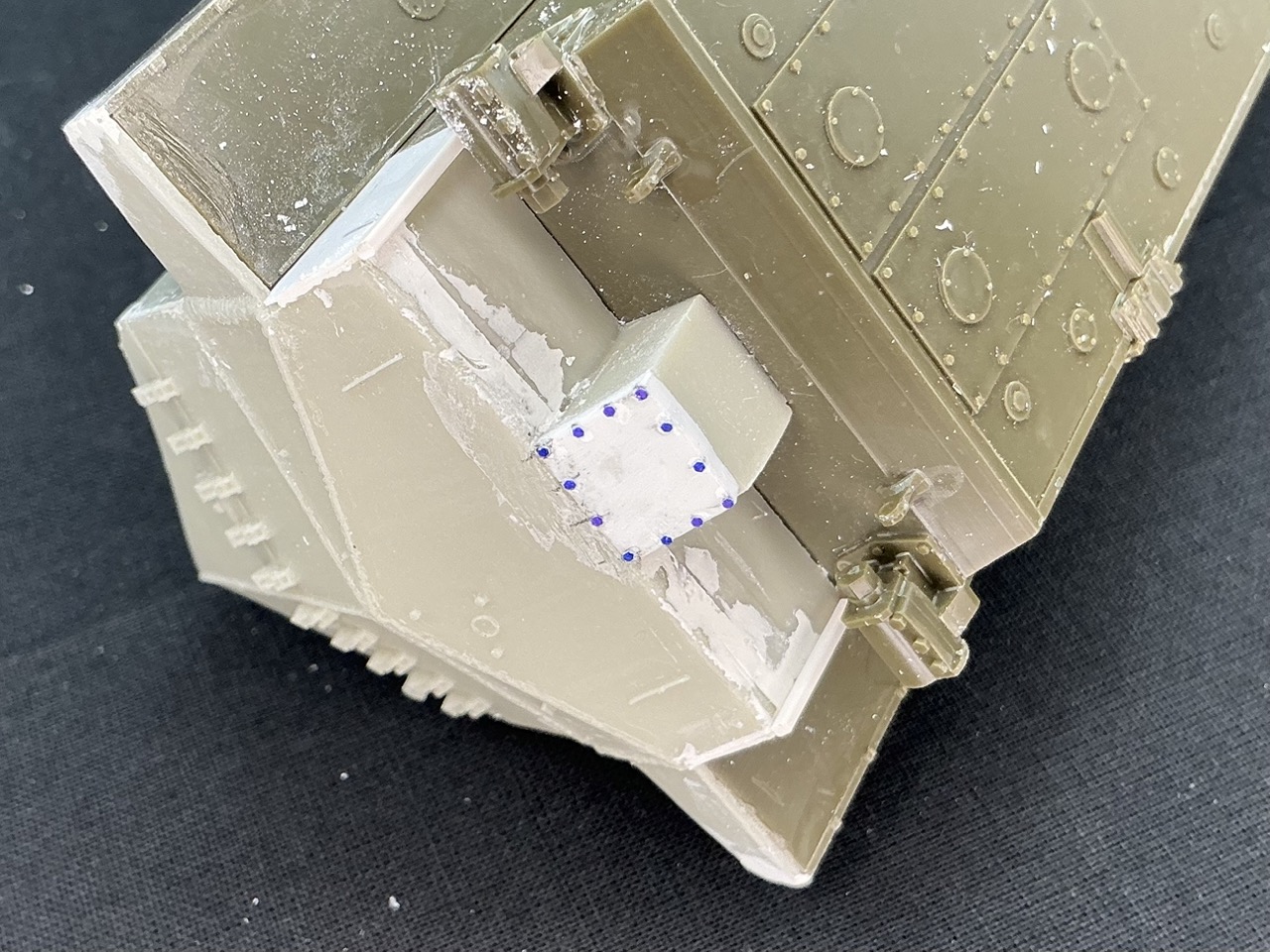
The reason for doing this is because I noticed in photos of the real BARV that the plate seemed to be angled inward more than the rear hull plate above it, whereas Resicast has it slightly the other way instead. It also had a treadplate pattern on it, but the real BARV in the photos doesn’t, so I used regular plastic card. The reason for the bolt heads being blue, BTW, is because I used card that I had coloured blue on one side with a marking pen, because I’ve used it in the past to punch domed rivet heads from, and for those it’s very handy to have it a different colour on the two sides.
At the sides, along the edges, I glued a piece of strip, because on the real BARV the side plates extend below the lower plate a little, but the conversion kit doesn’t have that.
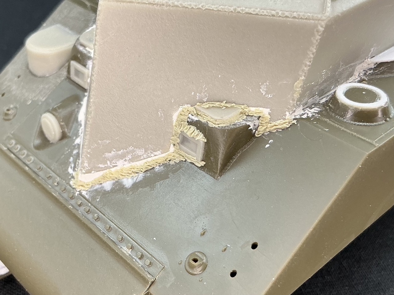
This is Magic Sculp two-part epoxy putty that I mixed up a very small amount of, then took even smaller amounts from that and rolled it as thin as I could in my hand before pressing it into the join between the parts. Getting it to stick there is tricky, especially once I began texturing it with the tip of a knife — it wants to adhere to skin and steel much better than to plastic, unfortunately But with a bit of perseverance it does eventually stick.
There also needs to be a weld seam on the outside of the driver’s window, but the putty had run out by the time I got to that. It also takes ages: the bit you can see here took me around twenty minutes, and I still need to do the same on the other side plus the whole of the rest of the join between the superstructure and the hull …