Sherman BARV

Weld seams on the hull front and lower rear now mostly complete:


I realised I probably won’t need to add them along the sides of the superstructure, because they will be covered by the catwalks and end up (mostly or wholly) out of sight. I do need to add them along the rear corners of the superstructure, though, where I had to fill the big gap with the rear plate.

6 Likes

On with the welds today. I started off with the Magic Sculp as before, but soon decided to switch to Green Stuff. I’ve got some that’s positively ancient, but which has never actually been used, so I figured: what do I have to lose? :slight_smile: By looking at the photos of the real BARV and the etched parts, I worked out that I do have to add seams to the sides of the superstructure, because the catwalks sit higher than I thought at first.


Kneading it was hard work, probably because it’s so old, and it stuck to the model even worse than the Magic Sculp. It sort of wanted to stay in the corners between superstructure and hull, but not at all along the rear edges of the superstructure, so after a while I ended up glueing it down with superglue before I even started texturing it. This may just be due to its age, though. On the positive side, you can roll it it into much greater lengths than Magic Sculp: at the thicknesses I’ve been using here, that has pieces breaking off the ends when you get it to a centimetre long or so, while I easily could roll out the Green Stuff to four or five centimetres at the same thickness.

You may notice I also added the smokestack/chimney/exhaust (whatever you want to call it), because the weld seams have to go over that as well.

3 Likes

What I do to ensure my added weld beads aren’t too wide is to lay down parallel strips of masking tape between them. Then I fill the gap with my putty, smoothing down to the thickness of the tape. Then I lift the tape, allow a few minutes for the putty to dry a tiny bit – then I texture the putty to mimic the weld.

Below is a weld seam I added to the turret side of the Tasca M32B1, mimicking the real thing. The masking can also be done on butt joint welds.

5 Likes

Thanks — I’ve done that before as well, but only when making welds using putty from a tube. Not sure how well it will work with two-part epoxy putty, especially if it sticks as poorly as mine did.

Okay, on then to the next bit of major work: the splash plate around the roof of the superstructure. Resicast usually gives you plenty of spares for parts you might lose or mess up, and these are no exception:

That’s plates for two BARVs, plus one jig to form them on, because they’re cast flat but need to be curved outward. The instructions tell you to use a hair dryer, and I prefer that to the hot-water method of heating resin for shaping, but … these just did not want to cooperate. I’ll spare you the details, but suffice to say I’ve seen that I’m not the only one having trouble doing this. Someone building one on some other site (I don’t recall which) replaced it all by soldered brass sheet, which I suppose probably means he was a railway or steam modeller before he discovered that tanks are much cooler things to be building models of. As I myself saw that particular light much earlier in life, I solved it the armour modeller way:


0.25 mm plastic card, onto which I simply put the resin parts and cut around them with a sharp knife. I then curved them by pressing them around an aluminium knife handle with my fingers, for which you need a much smaller diameter handle than the curve in the parts, because they bend back quite a lot. A bit more fettling later and they fit well enough, the Blu-Tack supporting them in the right position, of course.

The drainage holes in the underside are in different positions than on the Resicast parts, because I took their locations from the pictures of the real BARV I linked to before. The ones in the front plates were made with a round file, because I forgot to add them before bending the parts. Those on the side plates were made with a punch and die before bending, by making a mark where the hole was to go and putting both parts into the die at once, then punching out a half-hole out of both at the same time.

The third plate, at the back, still needs adding but I made a mistake measuring somewhere, so the ones I cut are too low. I’ll add them next time, as I don’t feel like making new ones just now.

4 Likes

I was waiting for this part of the build. Well done

2 Likes

Thanks, but I’m not there yet :slight_smile: I was already counting on making these myself, after I looked through the instructions and saw the heat-forming you’re supposed to do. I didn’t even bother trying it with the blast shield on Resicast’s Crab conversion, instead making a copy in aluminium sheet and plastic card, but I thought I’d give it a try here. To be honest, the plastic card is less hassle …

2 Likes

Good to know. Thanks for sharing your progress here

1 Like

You got the curves on the peak of the front splash plate to meet almost perfectly. A major engineering triumph on your part!

2 Likes

It’s not as good as it could be, but the fit wasn’t bad enough that I felt like remaking the parts. They touch at the top (and are glued together there) but there’s about a millimetre between them at the bottom, which I intend to fill with putty so that it should disappear, mostly anyway :wink:

2 Likes

All six panels are on now:

I filled the gaps between the front four with thinned putty, but not the gaps with the rear ones, because on the real thing they’re separate bits attached to the engine cover. I also put a round bar along the top edge:

This was simple enough to make by glueing 1 mm half-round rod on both sides. I was worried a little that it wouldn’t look properly round, but a little measuring told me that this “1 mm” material is actually 0.5 mm thick and 1.15 mm wide, so it works out well enough. All I need to do now is fill some of the gaps and scrape it all down smooth.

3 Likes

Nice work on those splash rails Jakko. They came out beautiful.

3 Likes

Thanks, but there are some curves in them that a better modeller would have avoided :slight_smile:

1 Like

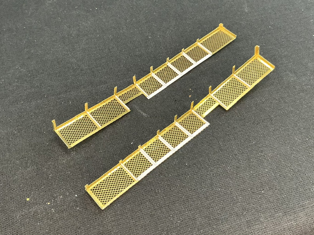
Now the heat in my hobby room is mostly gone again, on to the catwalk!

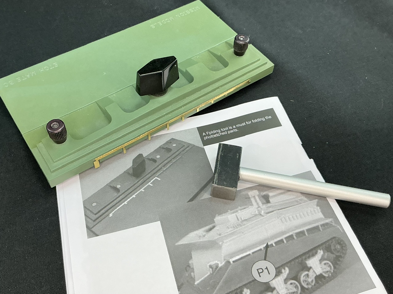
The instructions say to use a bending tool, and luckily, I have one of those. However, trying it the way the instructions show didn’t exactly work for me … The idea is to put the main part of the catwalk into the tool, leaving the legs sticking out so you can bend them upward. That mostly bent only the legs and not the horizontal bar above them, so I quickly flattened it all out again and tried again on the other side of the bending tool:

That way, I could push it down with the side of the head of a small hammer (from an RP Toolz punch & die set) and get it mostly square. It needed a bit more work to make it, and then bending the legs at the corners, before I could fit them to the hull.

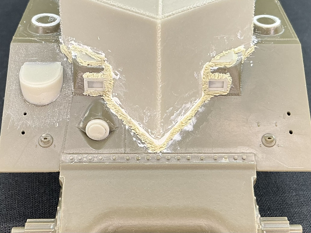
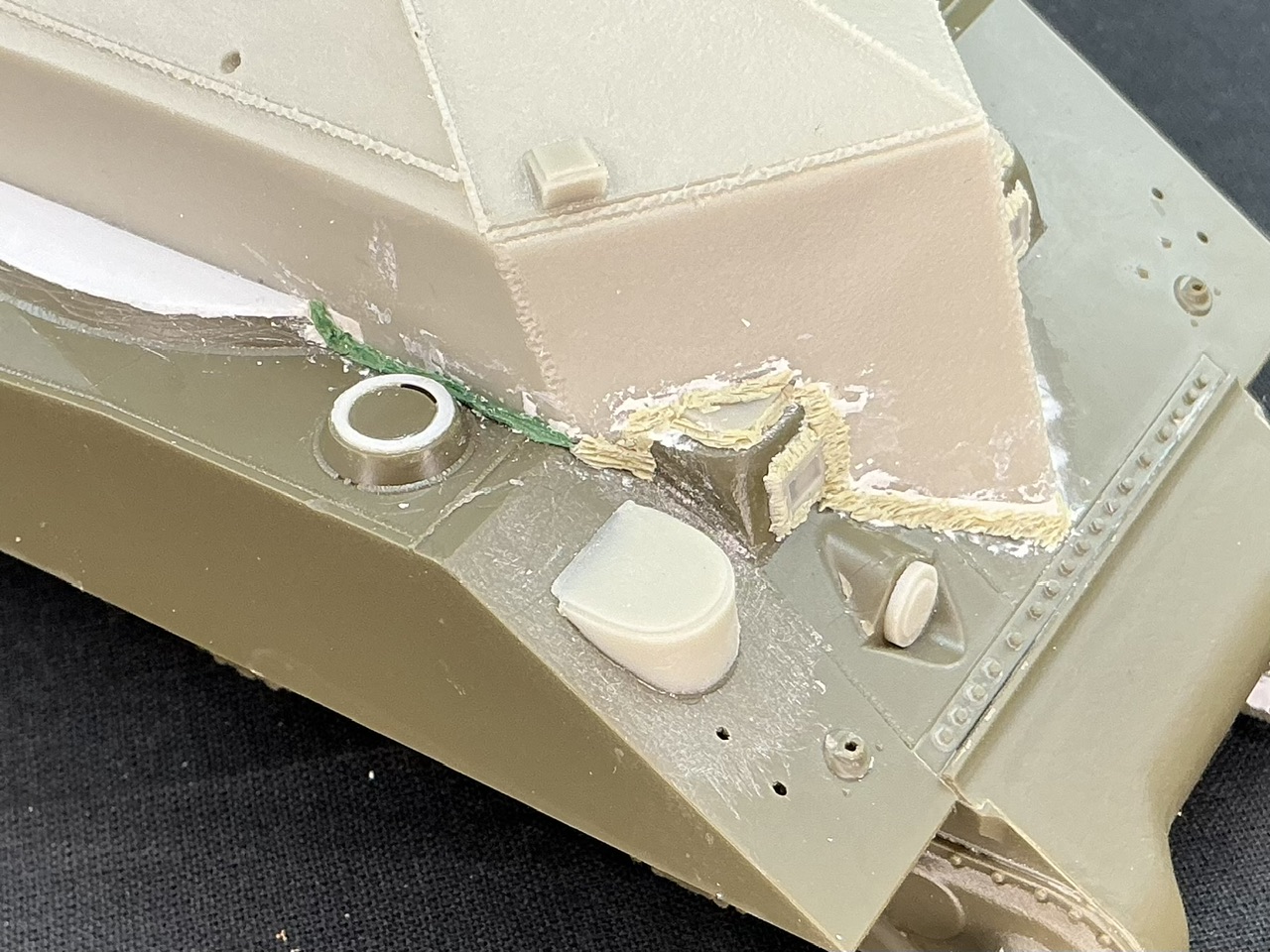
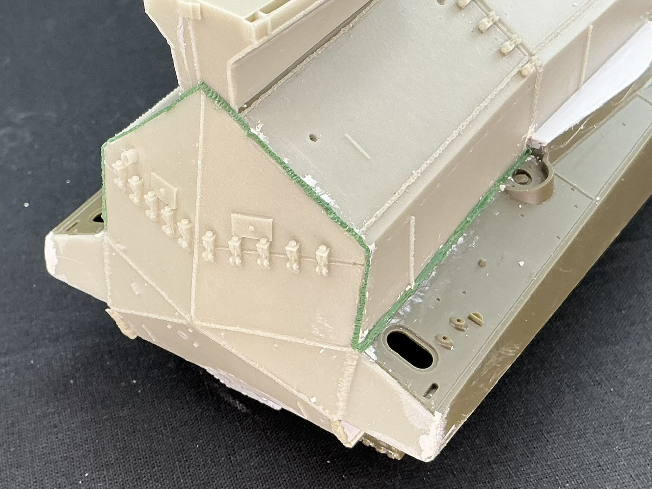
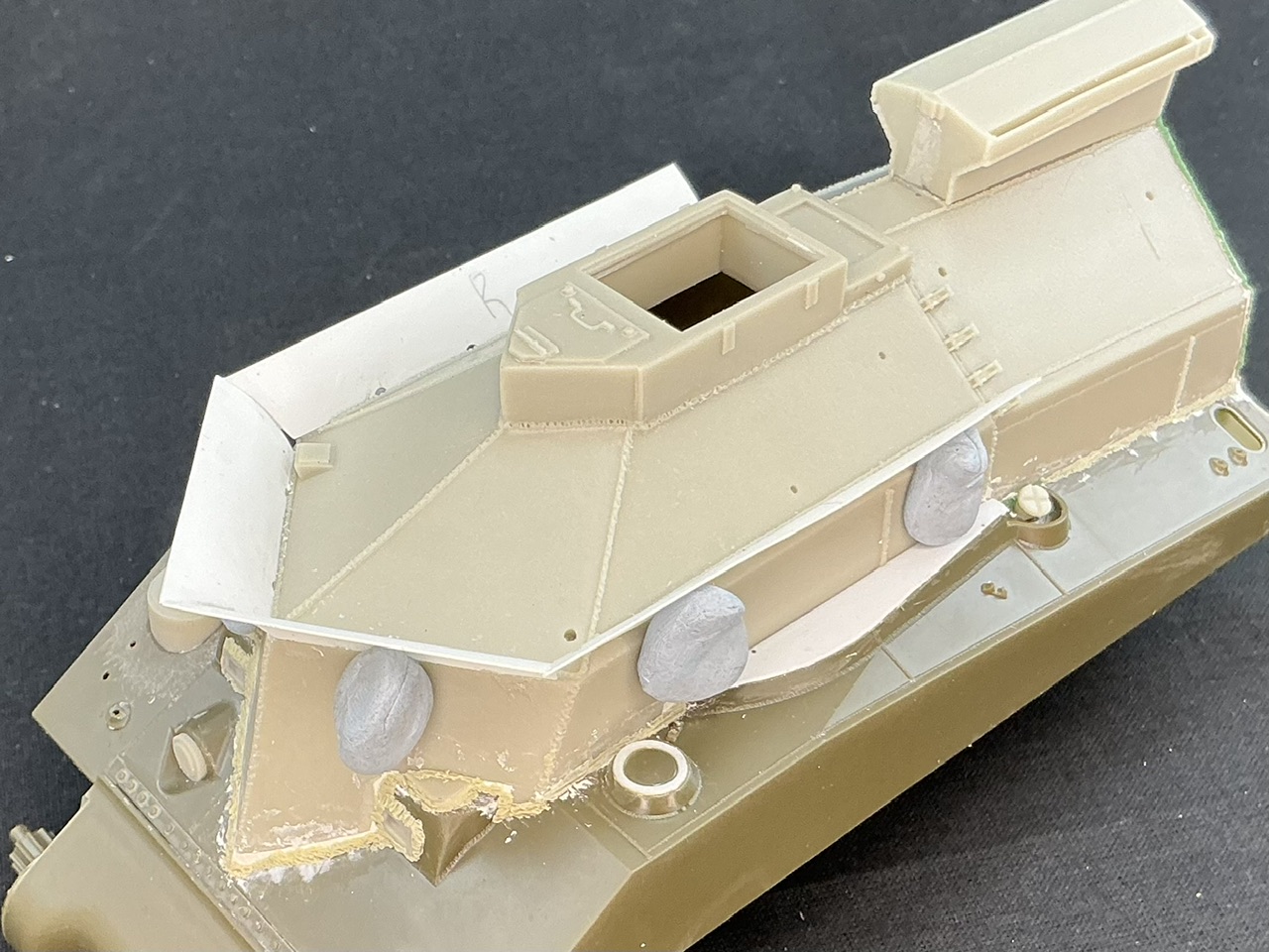
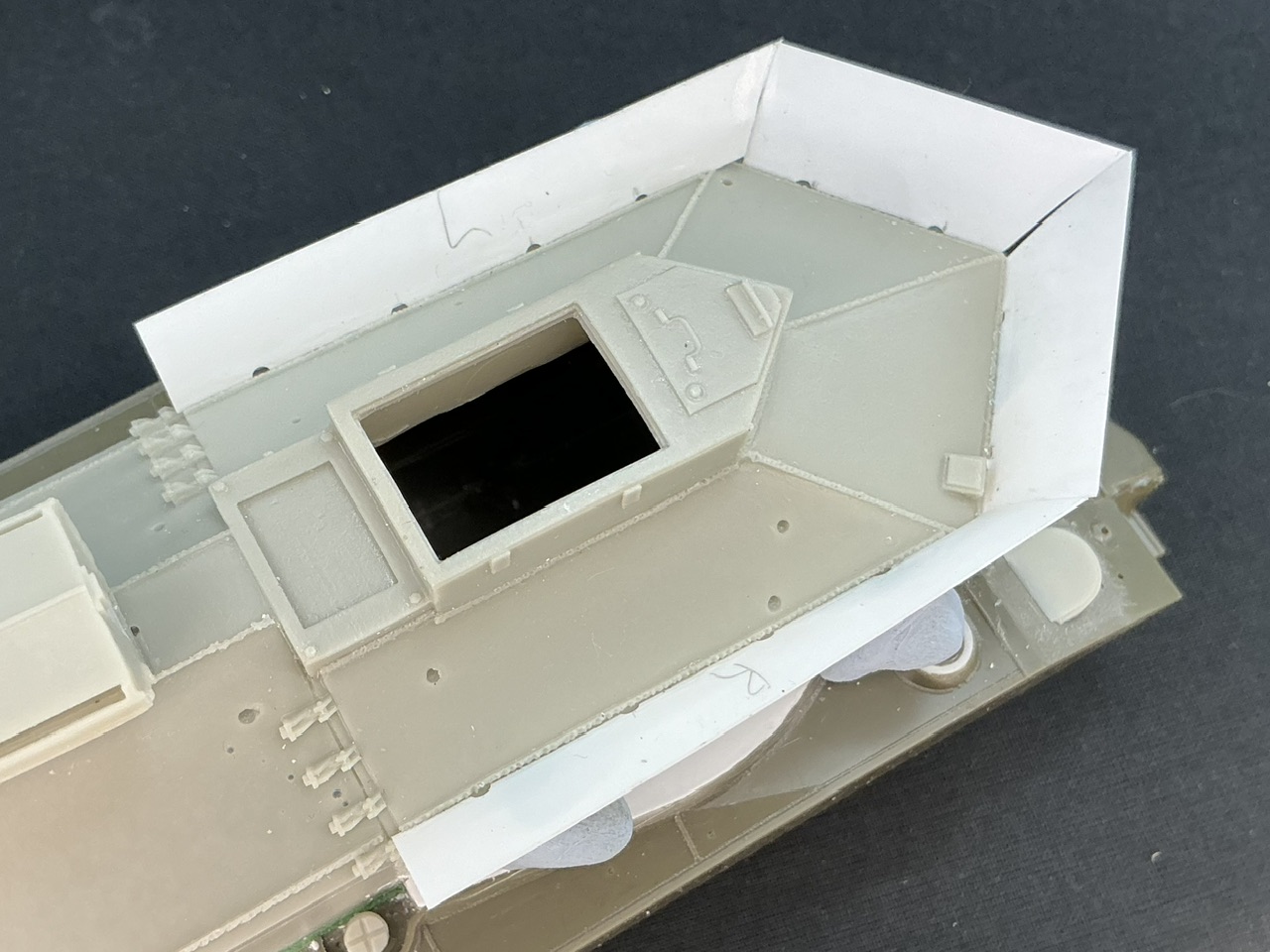
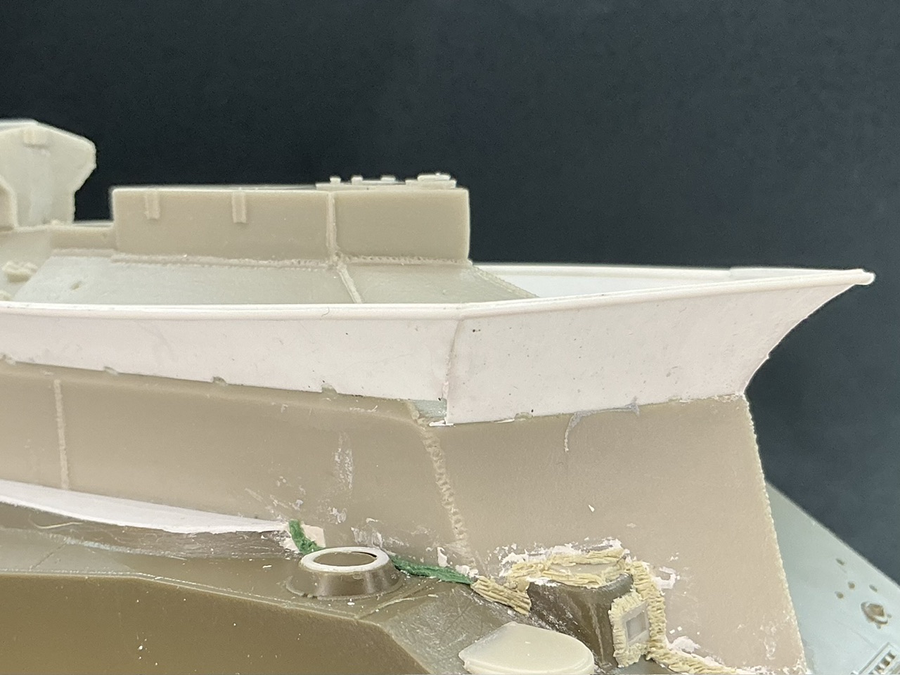
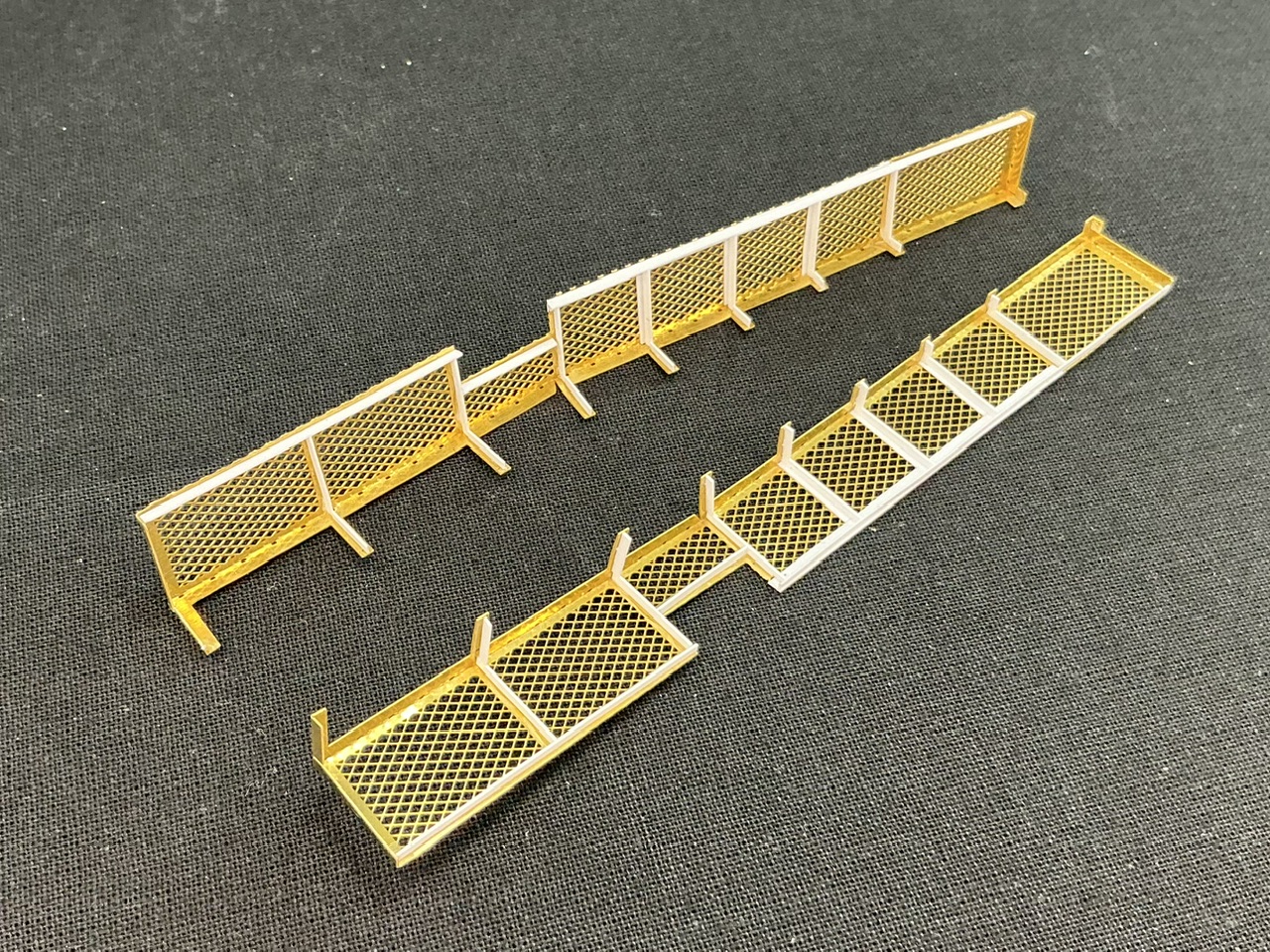
Or so I thought … Trying that showed up an oddity: there are supports “under” the mesh that don’t go all the way to the inner edge, but they do overlap the turret splash guard, so they look like they should sit on top of that. But if you do that, things don’t fit because the catwalk ends up angled inward. What is going on here?

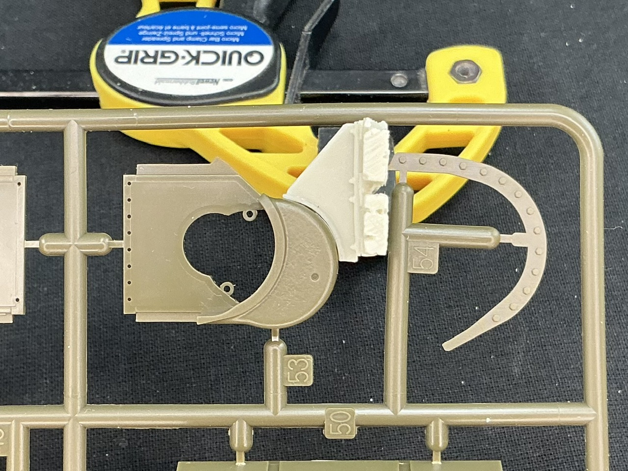
The short form of it is: Resicast made a mistake. On the real vehicle, those supports do go all the way to the inner edge, and there is a longitudinal one there too, not just at the front and rear like the kit parts have them. What’s more, those supports are L- and T-profiles: L along the outer edges, T everywhere else. Out with the plastic strip:

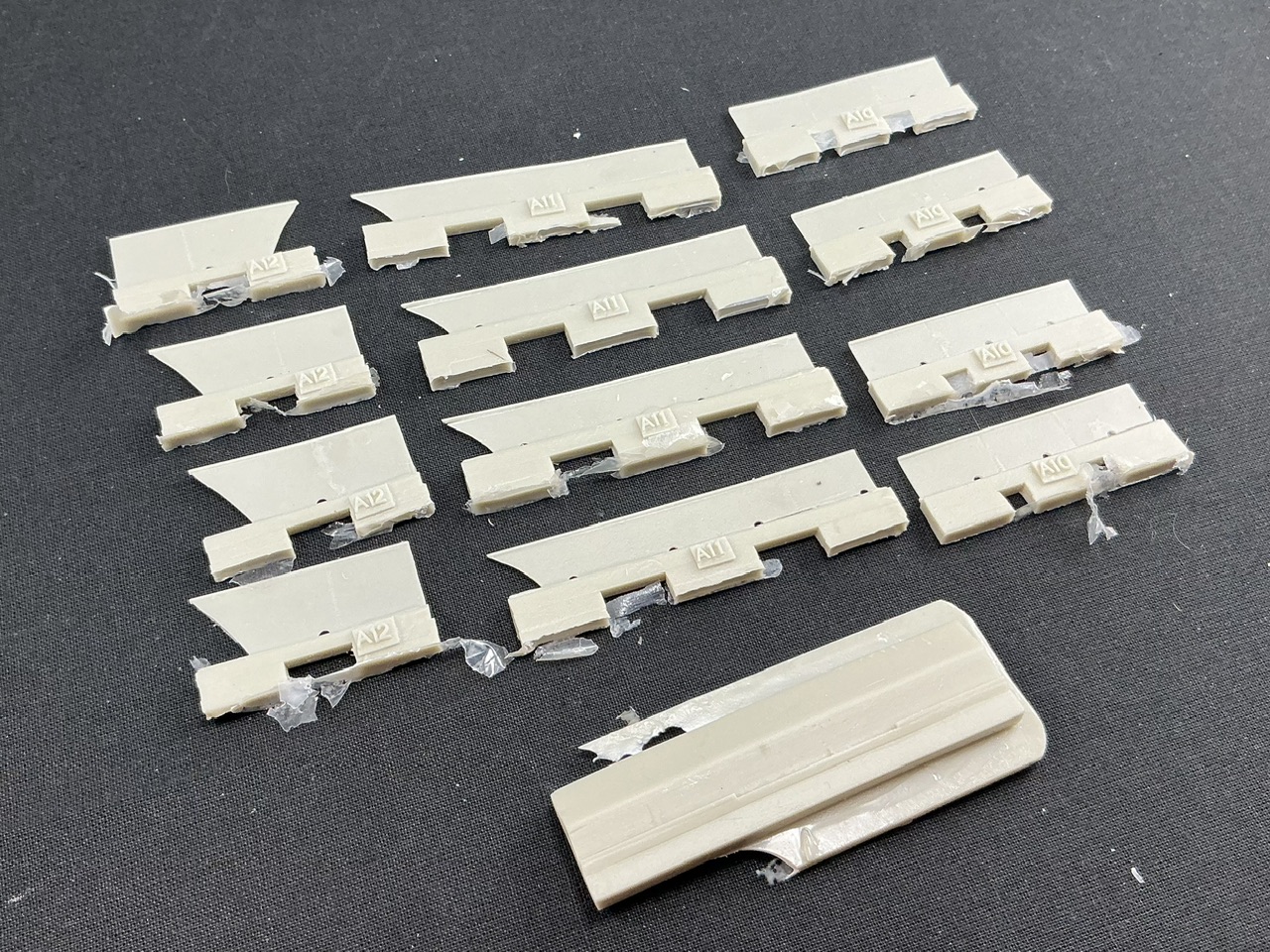
1.5 × 0.25 mm strip to complete the bits under the mesh, and 1 × 0.25 mm for the vertical bits. This is not even half of what needs to be added, but I’m letting the glue on this dry first.

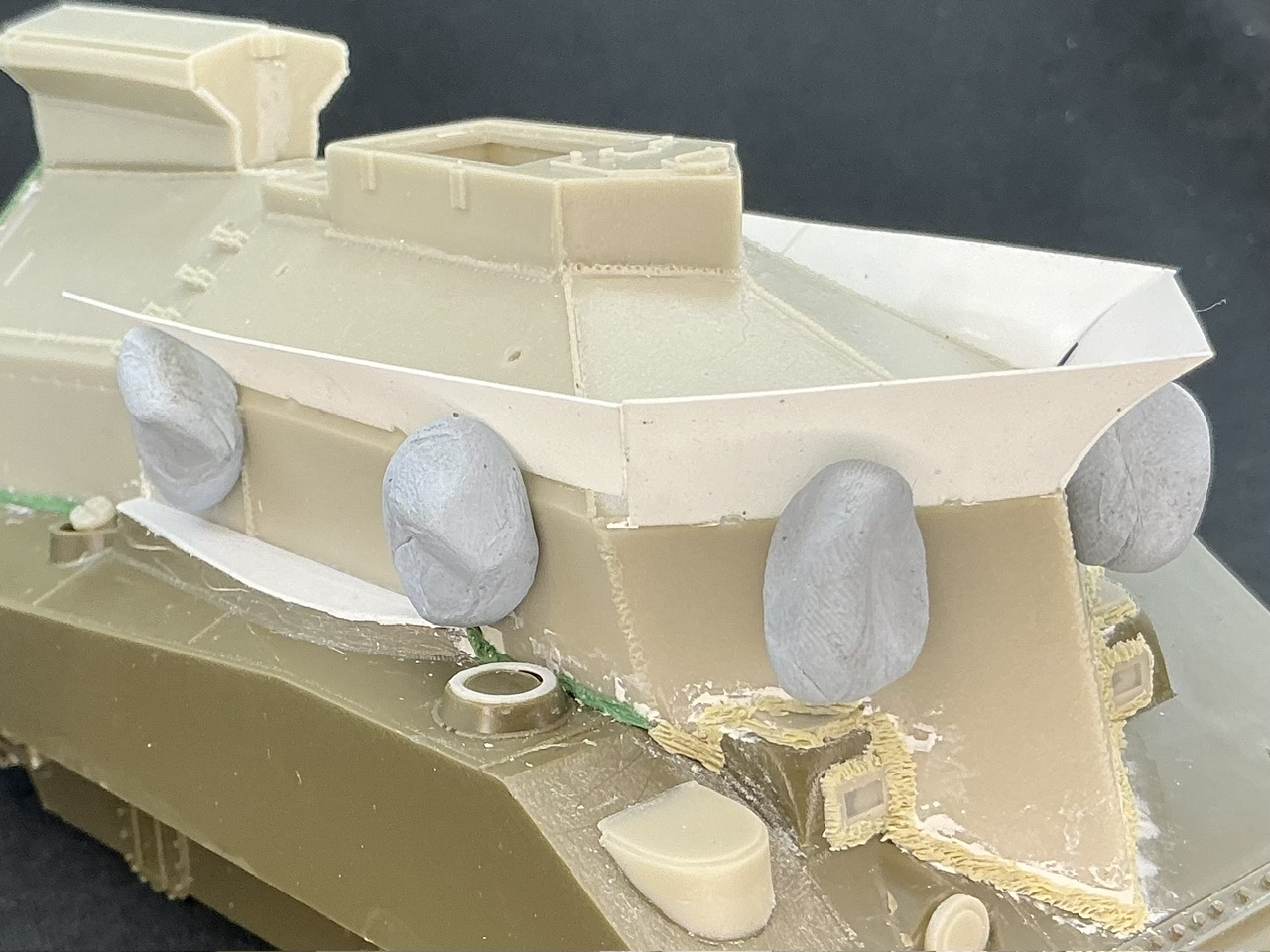
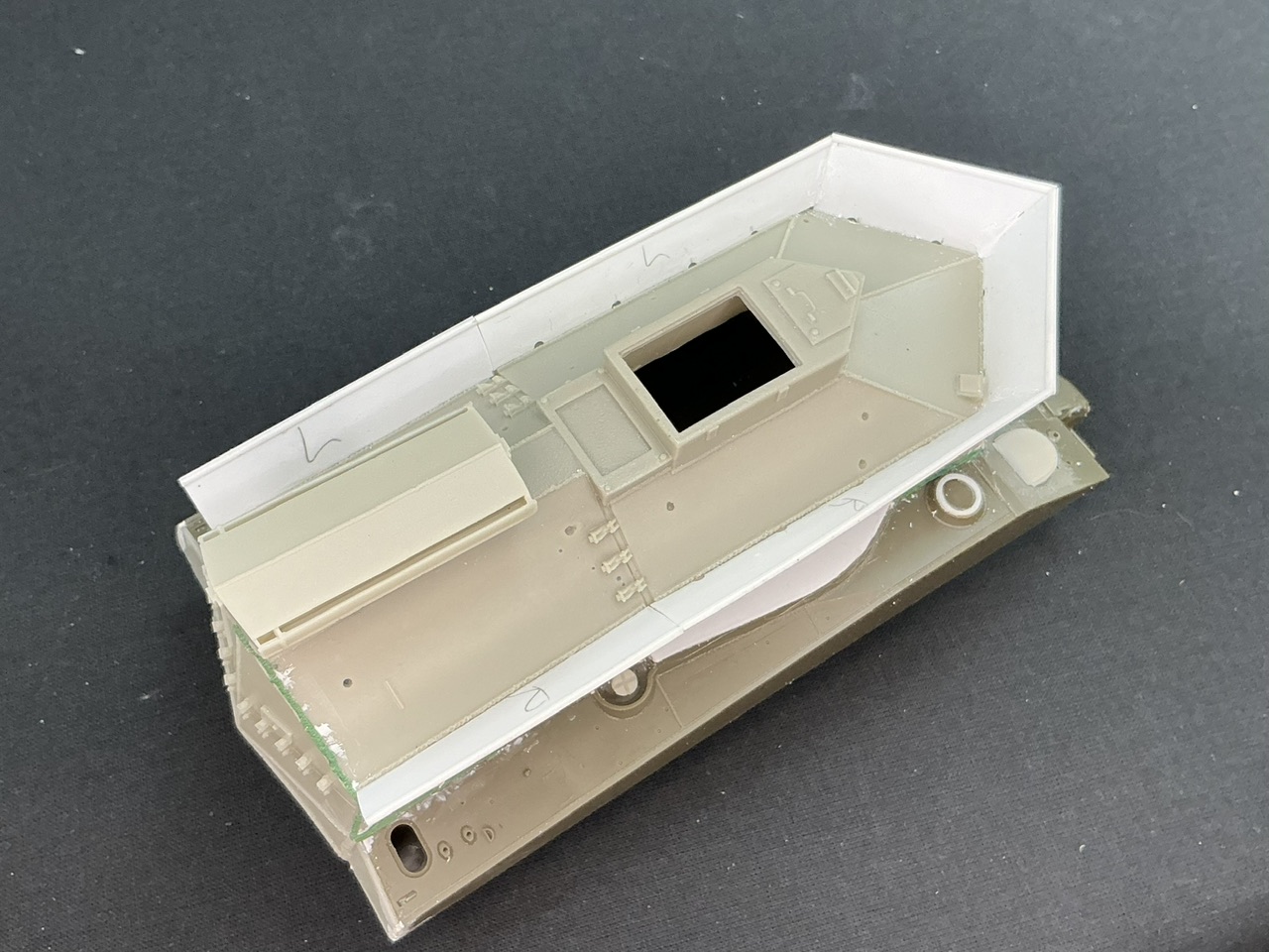
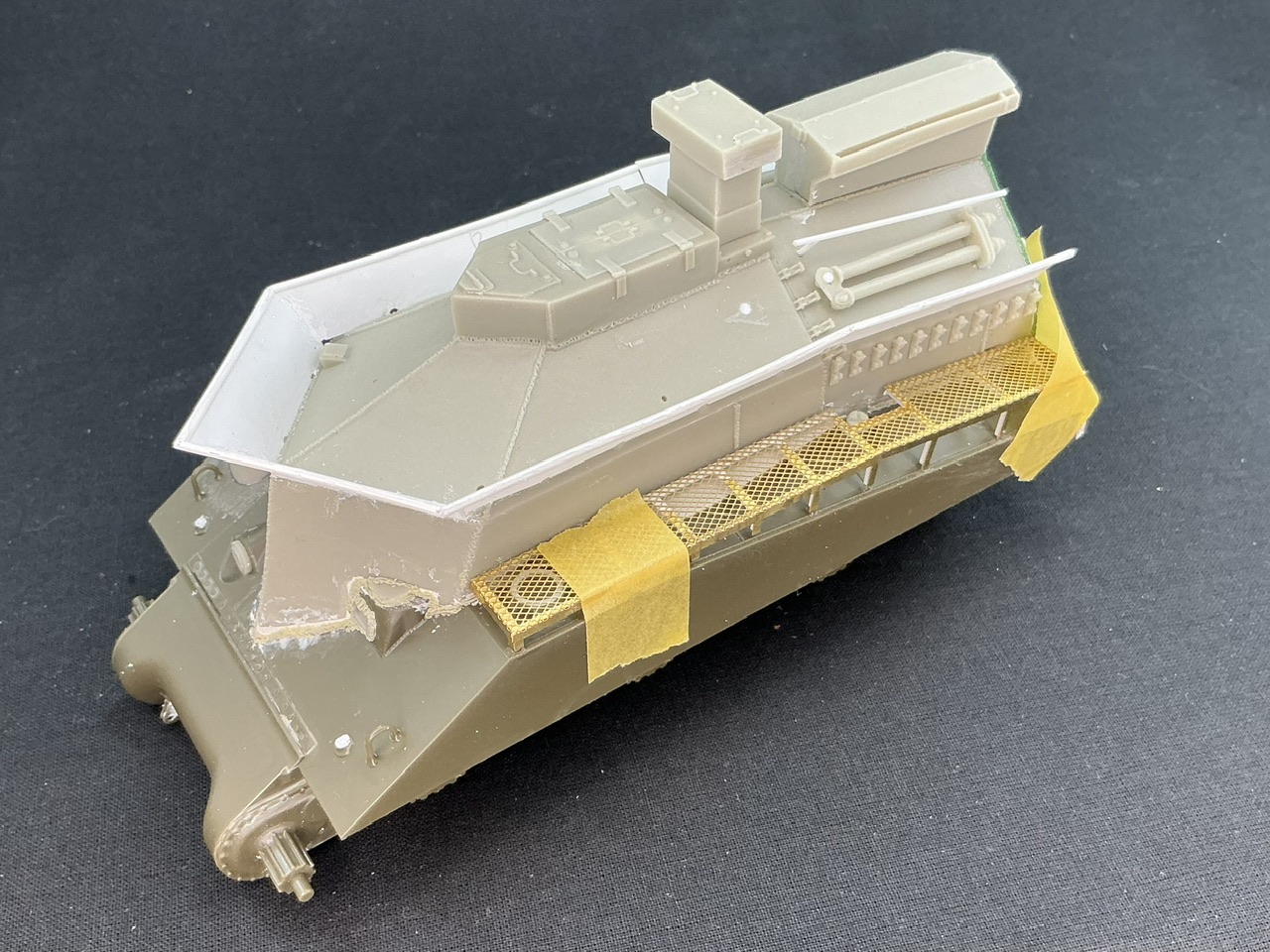
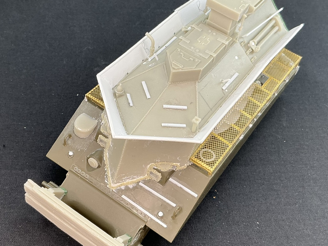
Oh, and I added stuff to the upper part, too:

The kit provides the hand rails, but they seem to have shrunk in casting, so they didn’t fit their locating holes. I drilled those out and made the rails from 1 mm plastic rod.

4 Likes

Catwalks now complete:

7 Likes

Looking great. I really like the weld beads.

Cheers,
Ralph

2 Likes

Thanks :slight_smile:

1 Like

The catwalks are now on:

I also removed the tow bar on the left and shortened it by 14 mm, because it was pointed out to me that the BARV carried two lengths, one for British and the other for American vehicles.

The bumper on the front doesn’t fit:

The reason is that the top of the curve doesn’t fit against the nose, which I solved by sawing a little bit off. Once the glue dries, I’ll have to add some more welds here to fill the gap that resulted.

A bit of thought showed why it doesn’t fit: it’s made for the three-piece transmission cover, and I installed the one-piece version. As you can see here, it fits perfectly well on the three-piece:

This is slightly odd, though, because Resicast tells you to use the one-piece one or, if you have one in your spares box, the three-piece. This suggests to me that the Tasca version of the base kit only had the one-piece version, so it’s odd that the Resicast part is made for the three-piece. The Asuka release has both, though.

4 Likes

Now the little details, the part of construction that always takes me much longer than it should. The BARV has a number of anti-skid ridges, but the conversion set only gives you three for the hull and those aren’t quite correct at that. On the real vehicle it’s a T-profile, welded on on its side, but Resicast provides etched parts that fold into an L-profile. A bit of plastic strip solves that easily enough:

The ones on the hull are simply two bits of strip glued into a T-shape. I made the ones on the superstructure that way too at first, but they didn’t sit right because the slope is less, and that causes the thickness of the strip to throw off the angles. After attempting to put a bevel onto the side of a piece of strip, which failed because you just can’t hold the strip well enough to do that, I took a piece of thin plastic card and bevelled that, then cut a strip from it. I could then, with some effort, glue it to the normal strip to make a T-profile with a bevel on the upright of the T.

Luckily, all of these ridges seem to have varied pretty much per BARV, so as long as they’re in these positions, the exact length isn’t that important.

I filled the holes for the pipe from the bilge pump and the two pieces of rod on the superstructure, then drilled new ones that are more correctly located than the conversion set had them. They’re probably not positioned exactly right, as I estimated it from photos, but it’s better than what it was.

At the bottom of the picture, you can just see that I also added welds to the bumper supports, where I had to cut those away to make them fit the transmission housing.

7 Likes

Excellent progress and good catch on those T shaped things that aren’t just L-angle iron

2 Likes

Thanks. I noticed it in the photos of the preserved one on the Leicester Modellers web page I linked to earlier, and it’s one of those things that, once you know it, you also see in other photos. It’s clear in this well-known photo as well, for example, because if you look closely, you can see the upper corners are bevelled, and you can’t bevel an L-profile like that but it’s easy with a T-profile.


(source)

4 Likes