Thanks!
Although I a now tempted by the fact that I can have a “real” Sherman idler wheel to turn into a coffee table ![]()
2 Likes
He’ll need a printer big enough for a diameter of 56 cm, but sure ![]()
2 Likes
A few more update photos…
First up, the kit comes with full sand shields, but also includes the parts for the Korean War era fenders. Those work for the front, but in WWII the rear mud flaps were not part of the issue of the vehicles, and when crews removed the sand shields, a strip was left on the rear fender area that was not included. I made those from strip styrene
then I let those dry in place, painted the undersides, and later weathered them with Mig Ammo Mud like the rest of the suspension and fender undersides
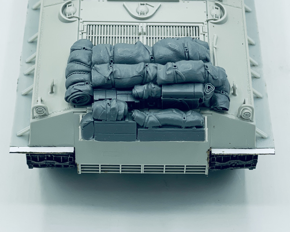
lastly I started adding some Value Gear stowage to the rear luggage rack and engine deck
I also finished adding mud to the road wheels and idler wheels on the suspension
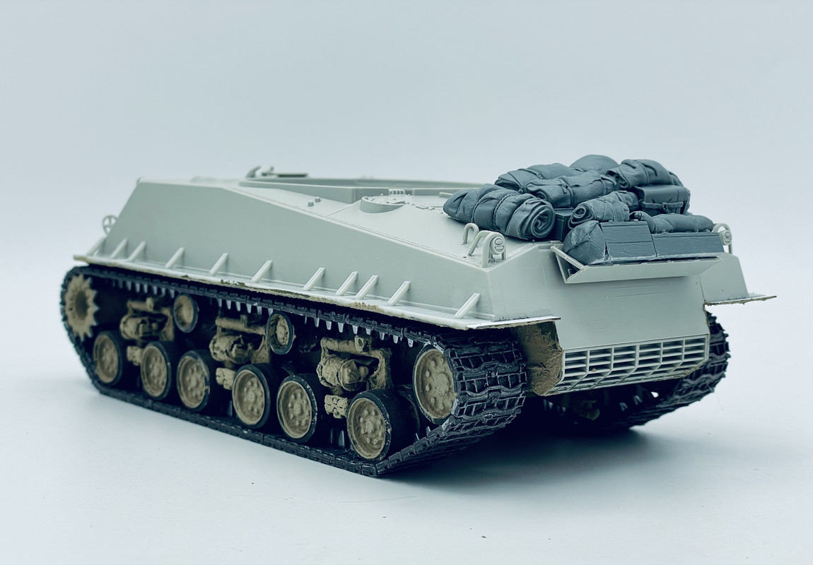
I’m just about ready to add the lower hull to the upper hull after a bit more work in there…
9 Likes
Front of the upper part of the hull
Stages 11, 12, and 13 of assembly completed.


Here are the suspension springs in action as well.

6 Likes
By now I’ve also started on the turret:

In the photo of the real Churchill after it had come ashore, you can just make out that it had the extra shield on the coaxial machine gun. For the 75 mm gun, I used the early barrel with a flared end instead of the later one that has a constant taper — you get both in the kit. Because Churchill’s barrel had its muzzle taped up for wading, it’s not clear which of the two it actually had, but based on the other early features (hull with direct-vision flaps, gunshield without “wings”, bogies with skids that don’t curve forward) it seems a logical assumption to me. In any case, you can barely tell the difference even when you know what to look for ![]()
5 Likes
@Stikpusher
It’s impressive what you’ve done with that old kit, it’s looking really good. Are you planning to keep the original gun? I had issues with a lot of things on that kit, but the undersized gun was something that really bothered me on mine when I built it over 25 years ago. Are you keeping the original gun?
1 Like
Good morning team (my time at least)! After carefully trying to figure out how to mask the turret and floor for repaint I’ve decided the risk of large scale damage is to great and I’ll correct the mistake on the next build (I have another Academy M10 in the stash). I’ve got the hull and turret painted in Tamiya lacquer Olive Drab, with a little black basing around where I think shadow would be created by stowage etc. I’ve glued on the grousers and have cut out the applicable decals for application. I’m going to paint the track guides on the tracks steel and weather them accordingly, as well as the grousers attached to the hull. Still figuring out how I’m going to attach the tubes to the glacis plate and hull sides and what I’m going to make the out of. Possibly thin brass tube or styrene rod drilled out to make the tube walls as thins as possible.I assume the tubes were added so a canvas tarp or camo nettting could be placed over the vehilce to, in the canvas tarps case, keep the rain and sun out when bivvied.
 P8100001 by Chris Wilson, on Flickr
 P8100002 by Chris Wilson, on Flickr
 P8100003 by Chris Wilson, on Flickr
Chris
6 Likes
Thank you! Yes I am keeping the kit gun. Aside from some minor mods like stowage, the missing rear fender strips and adding an antenna, I am trying to keep this kit as original as possible. Oh yeah, I’m adding some crew figures as well.
2 Likes
Okay decals are on, such as they are. Tomorrow it’s painting the tracks and weathering. Still thinking about stowage, value gear make some good commonwealth stuff which while for the Achilles will fit the Wolverine equally as well. I’ve yet to apply the tools, I have them painted on the sprue and I’ll add them before weathering.
 P8100004 by Chris Wilson, on Flickr
 P8100005 by Chris Wilson, on Flickr
Chris
9 Likes
Very interesting idea with the M4A3 (90) HVSS with T26 turret on the M4A3E2 “Jumbo” hull. First time, I see this drawing.
When I first saw the picture of the M4-based proposal with the T-26 turret, my mind began to wander (it does sometimes, and I live with it ![]() ).
).
To gild the lily a bit further, these additions to the M4A3E2 based variant would also have been possible around late 1944/early 1945.
- slat armour to counter handheld HEAT weapons like the Panzerfaust. Think Strykers in Iraq or Afghanistan.
- a large turret box to hold all the crew gear (tankers never have enough room for their gear). The one from the Canadian Leopard 1C2 is shown just because, it is huge in relation to the turret.
- the longest barrel variant of the 90mm (M3?)
These features on the M4A3E2 hull with HVSS.
I came very close to actually starting this project, but another “What if” project took my attention in the end: Hypothetical - what if M103A2 in service with the IDF - Israeli Defence Force


The real life spoiler to this happening would of course have been lack of engine power. The 500 HP Ford engine of the M4A3E2 was already to small to fit the task, so an uprated or different engine would have been needed
3 Likes
I don’t think anyone would have gone for slat armour. Technically, of course, it would have been trivial to add. But did anybody in the early 1940s consider that such armour helps much more against low-velocity HEAT weapons than the same weight of simple armour plate does? I rather doubt it. Sure, everything is possible with a what-if model, but IMHO unless you can show there was an interest in this kind of armour in the USA, I wouldn’t consider it very plausible or realistic.
2 Likes
Also, on with Sherman Churchill ![]()

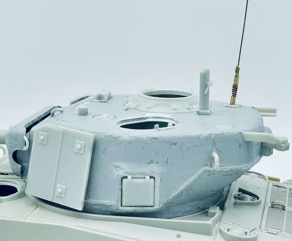
More details added to the turret, including that I cut off the mount for the searchlight to the left of the ventilator, because this was introduced later than this tank would have left the factory. That also goes for the devices on the commander’s hatch doors, which lock them in the open position, so I also cut those off from the outsides of the hatches, but that’s not visible in the photo. The lifting eyes on the rear sides of the turret are in the “high” position like on the real Churchill, which again points to it being an early tank. The base plate for the British sun compass is just visible in the picture of the tank as it leaves the LST, so I also put that on, as well as British aerial bases.
On the hull, I cut away the bullet deflector in front of the row of bolts, which is one of those annoying jobs that I always kind of enjoy doing ![]() If you look at how the five spare track blocks lie on the glacis in the photos of the real tank, it seems very unlikely that Churchill had that deflector — again a sign of a very early production M4A2. The etched guards for the head- and taillights are not included with the kit (they weren’t missing, they’re not supposed to be included with this kit in general) but come from the M4A2 I converted into a BARV, which doesn’t need them at all so they came in handy here.
If you look at how the five spare track blocks lie on the glacis in the photos of the real tank, it seems very unlikely that Churchill had that deflector — again a sign of a very early production M4A2. The etched guards for the head- and taillights are not included with the kit (they weren’t missing, they’re not supposed to be included with this kit in general) but come from the M4A2 I converted into a BARV, which doesn’t need them at all so they came in handy here.
3 Likes
Hi Jakko,
I agree, slat armour was not seen, or to my knowledge tried by the US during the war. But standoff armour was known to the US military, Think German “Schürzen” as on the Panzer IV. Or the “bedspring armour” on for instance the Russian T-34.
So the concept of standoff armour was known, and could have been applied to a US “Super Sherman”.
Anyway, it is just an idea for a “what if”-model ![]()


3 Likes
True, the Soviets used what’s basically a primitive form of slat armour at the end of the war in Europe. But even if this was known to the US Army (which I doubt) at levels where it matters, reading books like American Thunder by Richard Anderson makes me think it would be highly unlikely to ever have gotten any kind of official sanction.
The German type, though, is not stand-off armour against HEAT rounds but against 14.5×114 mm AP rounds. That was not a problem the Americans faced, so they clearly wouldn’t adopt a similar solution.
1 Like
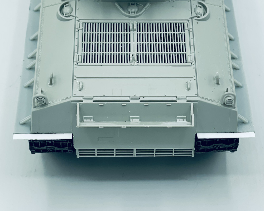
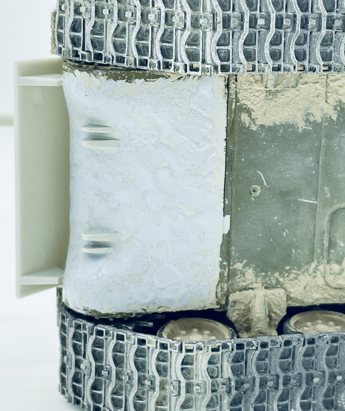
Aside from sticking more stowage onto the back, I made a small correction to the engine deck to backdate it slightly: I filled the seams at the back to the left and right of the central part and scribed new ones slightly inboard. I also added the sand shields:

To do that, I first put the drive sprockets onto their axles, without glue, and then added the front two sections — because the rear part had of course been fitted to the engine deck to serve as a stowage rack. The middle portions didn’t have a slot in them on the real tank, so I filled those by smearing putty into them from behind, letting it come out on the front and scraping it down once it had dried.
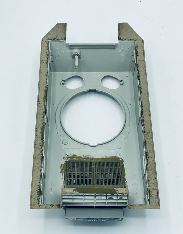
After that, I had another thing to figure out, because in the photos of the real Churchill it looks like there’s a strip behind the middle section, but it doesn’t appear to be the normal one that was welded to the hull to fix the sand shields to — this tank was too early to have those. But what was it? By looking closely at pictures of British Shermans in Italy, such as this one, my conclusion is that it’s a strip that was attached to the little blocks that were welded to the undersides of the sponsons, which were the early way of fixing the sand shields. But I had cut those off because the instructions told me to … OK, put them back, then, and stick a bit of strip to them:

5 Likes
I realize that I have not been posting progress of my Sherman build here.
Lower hull is done less the dozer which I began assembling today. The Heavy Hobby tracks went into the bin and Quick Track version are en route.


7 Likes
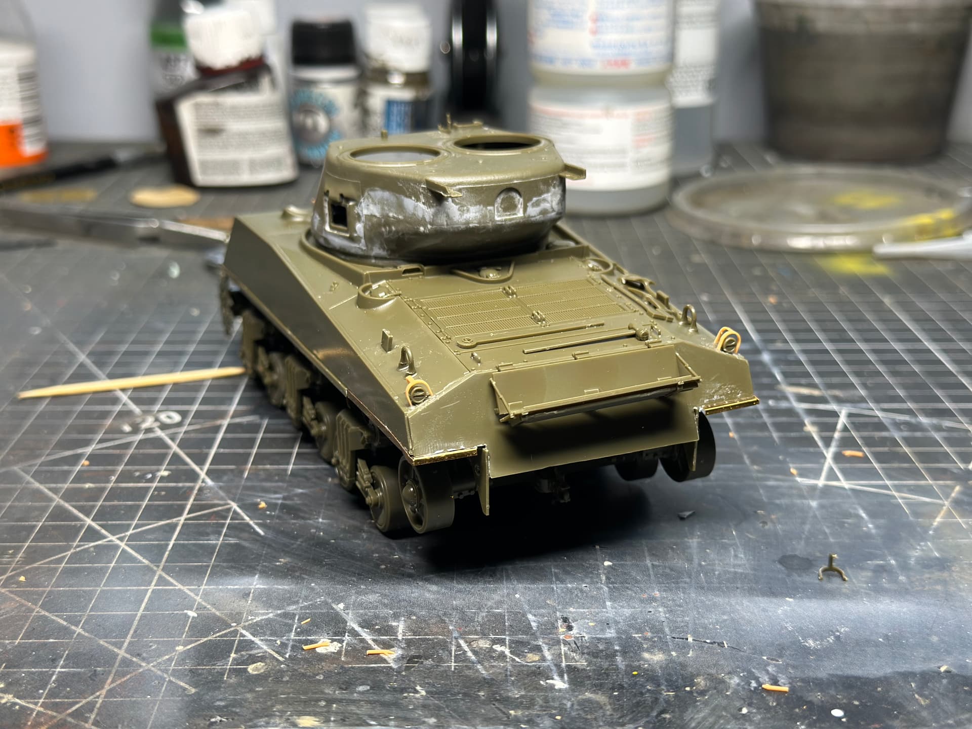
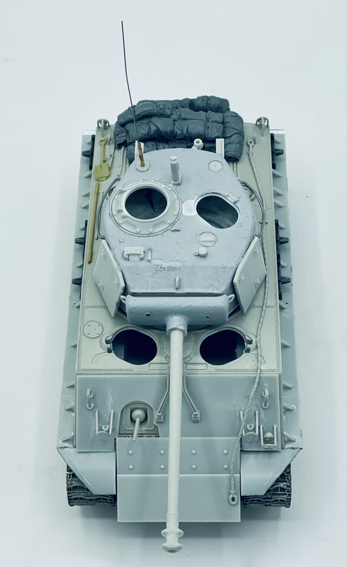
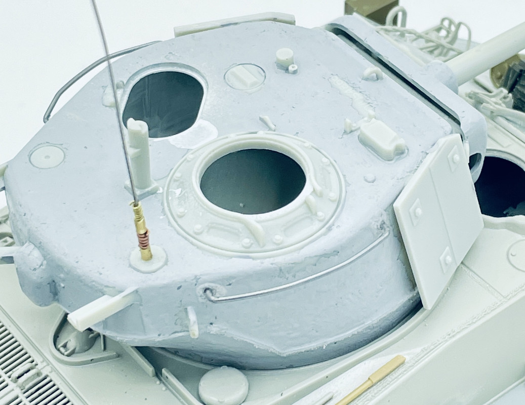
Over the weekend I made some small bits of progress and today I was able to get basic construction wrapped up…
using Mr Surfacer, I added casing texture to the differential housing and turret… then using some very fine styrene rod I added a weld bead around the turret. I also scratch built up an antenna base using music wire telescoping brass tubing, an d some fine wire. it’s not an exact replica, but the kit did not come with any antenna base at all…
And lastly I got the upper and lower hull halves glued together after more weathering painting on the tracks, and glued the differential housing add on armor plates.
All ready for painting and adding the final bits such as hatches, .50 cal., tow cable, and such…
9 Likes
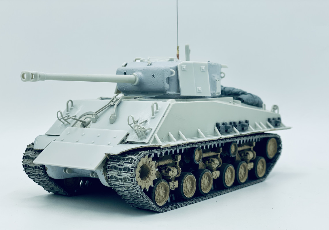
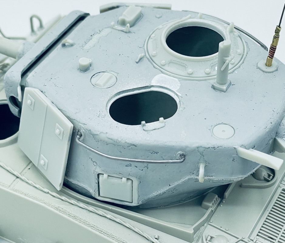
I made some more progress this morning…
I glued the tow cable into place on the upper left side of the hull, as was standard stowage position. I also added some grab/cargo rails on the turret side using music wire. That stuff sucks compares to brass wire, but Hobby Lobby doesn’t care the .020 or .030 brass wire anymore…
and lastly I added some assorted front stowage based upon what you can see in this photo here
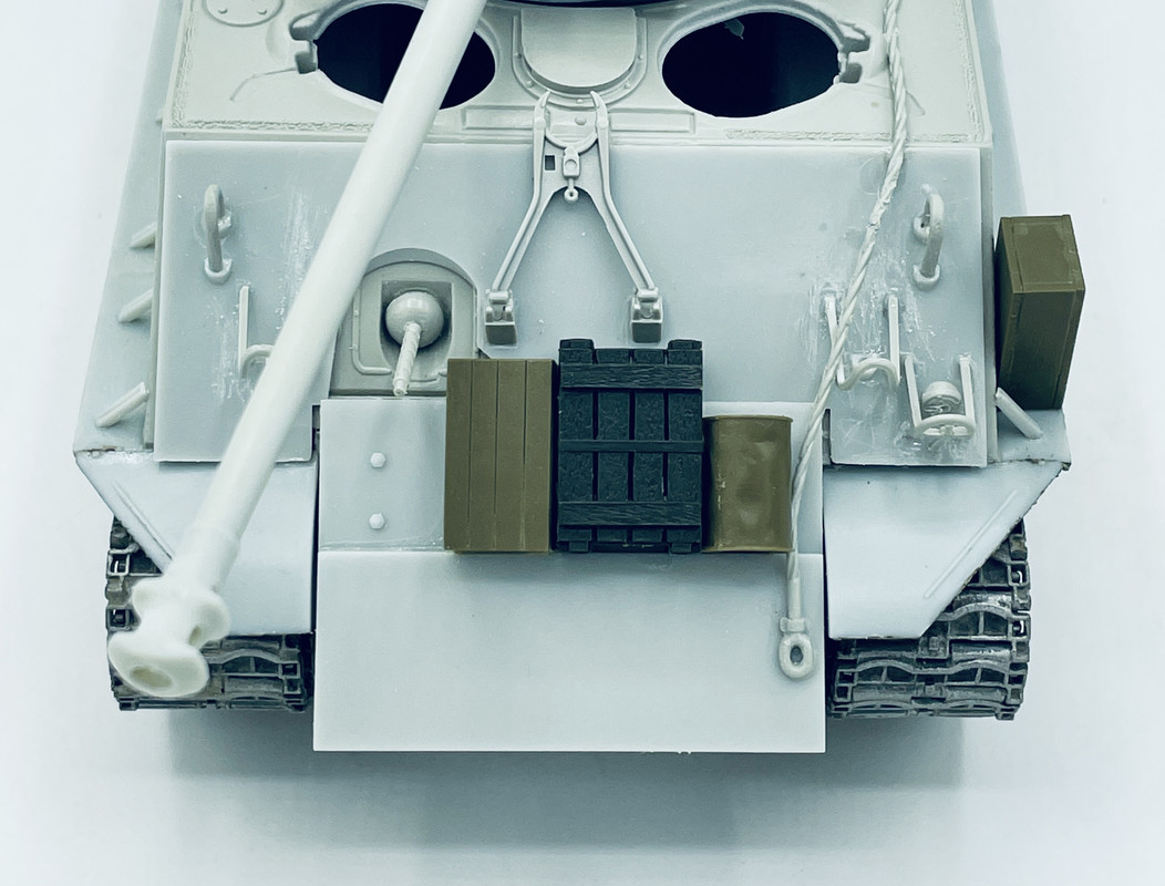
I just need to add some packs to the sides of the turret and this will be all ready for priming and painting…
4 Likes
A good source for copper wire is to take apart an electric device that has a transformer in it or — if you can find one — an old monitor or TV with CRT.
2 Likes
Oh yeah, I have plenty of salvaged wire of various gauges for modeling purposes. Thats what I used on the spring portions of the antenna base. I’m just running short on brass rod currently. And fewer and fewer local shops & stores carry the K&S stuff. I need to check the local hardware store…
2 Likes