Looking good! 
1 Like
Awesome progress
1 Like
Thanks for the compliments 
I need to make a couple, coupler heads. I thought I was going to use the ones from an O-Scale rolling stock I already have in the stash but I will not. They are actually too large for this project in 1/35. And a different style that I need anyway.
Remember that old thread in the old forums regarding telling the model RXR industry to make a 1/35 scale RXR standard? I said something like, “sure I’ll vote for it but I don’t see the need.” Well now I see the need for AM 1/35 scale RXR parts and accessories now
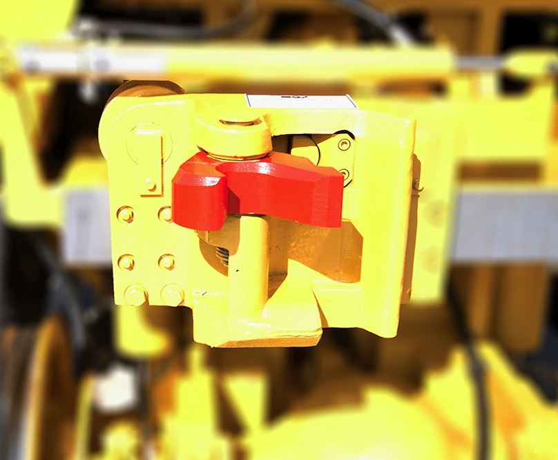
This is the style I need to make for this project.
3 Likes
Isn’t that always the way ![]()
Looks like an item crying out to be 3D printed ![]()
1 Like
3D printed… I hadn’t thought of that 
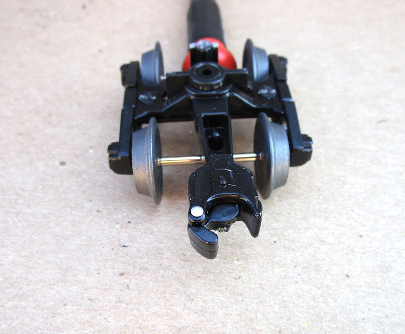
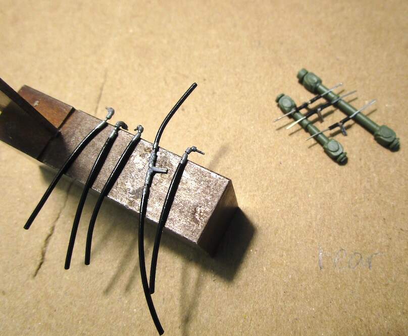
Couplers and heads scratch built from spare parts… I’ll complete these tonight (this weekend sometime)

3 Likes
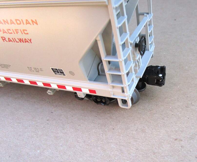
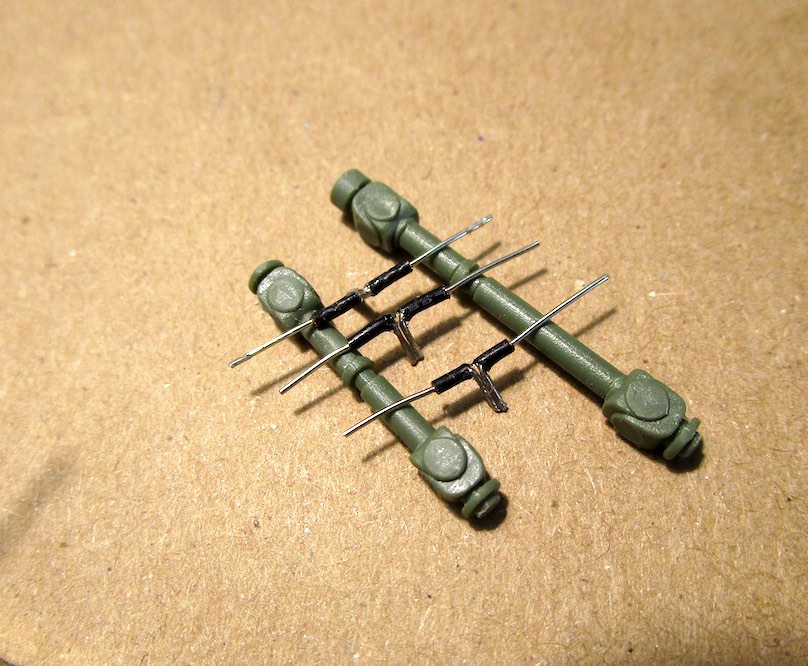
Couplers are artistic representation based on 1:1 prototypes. Scratch built with spare parts 

poster tacked in place for the pictures
Thanks for looking …
5 Likes
Excellent work, they look fantastic
1 Like
Thanks for the compliment and for checking in. I’m seriously trying to complete this on time 

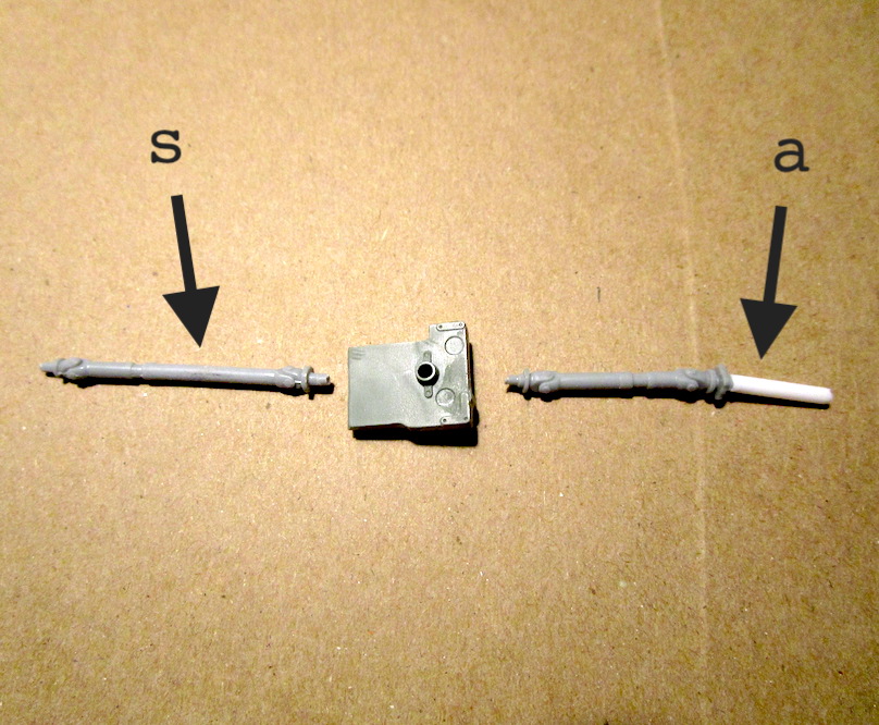
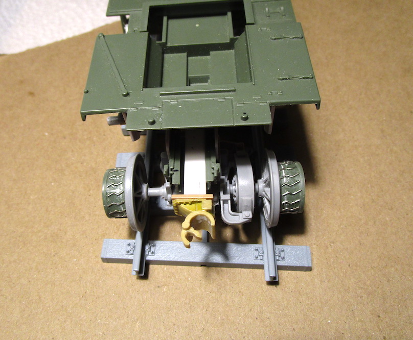
(s) = shortened an extra drive shaft part from another kit (RG-31 Mk.5 MRAP)
(a) = additional length of plastic tube to enable the traction differential to slide forward and backward
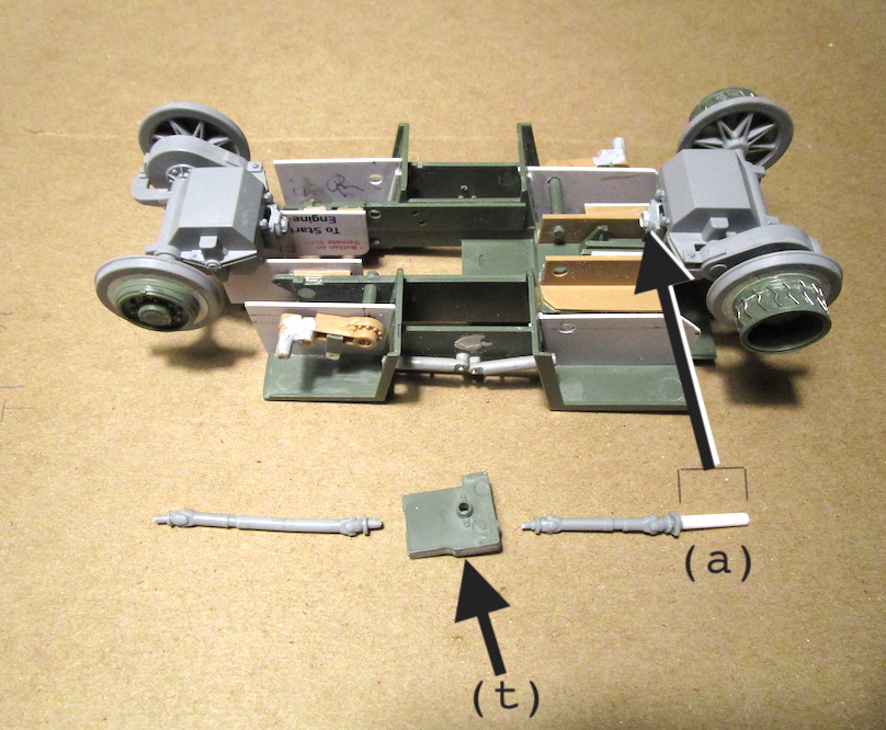
(a) = inserts into traction diff
(t) = transfer case part (A56 & A60) from the Feldumschlaggerät kit
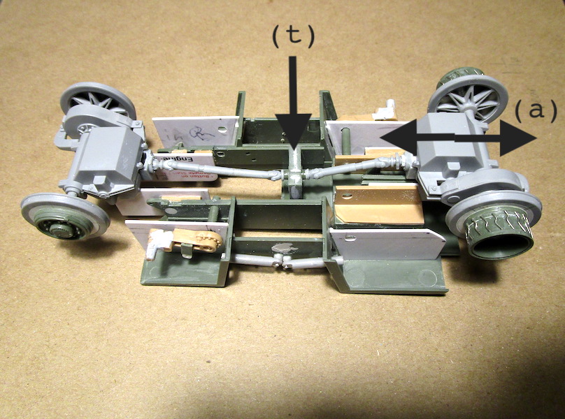
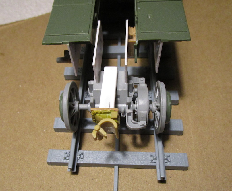
Drive shafts and transfer case installed
… thanks for looking
5 Likes
Looking really good
1 Like
Thanks for the compliment
Working on the hydraulic fittings and hose now. I made them this way so the road wheel arms can articulate so the hose will have to flex with this activity. In my head this will work. I haven’t installed them yet so I don’t really know…
5 Likes
I always mentally prepare to properly text my WIP posts but by the time I optimize the images and then log-in, I forget most of it. I’ll try to be as clear as I thought I was going to be 
The I-Sheets for this model are complete but some steps are not completely clear in detail. I often referred to @BlackWidow 's FUG build thread.
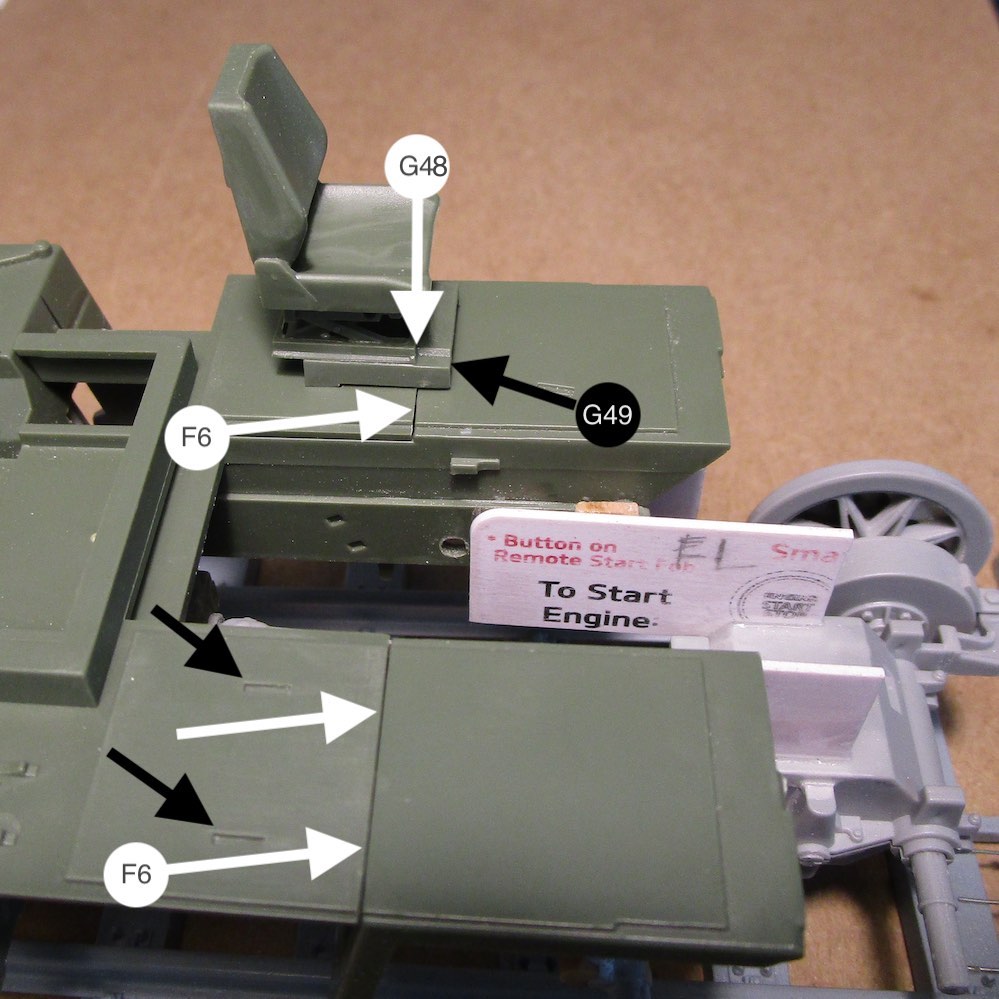
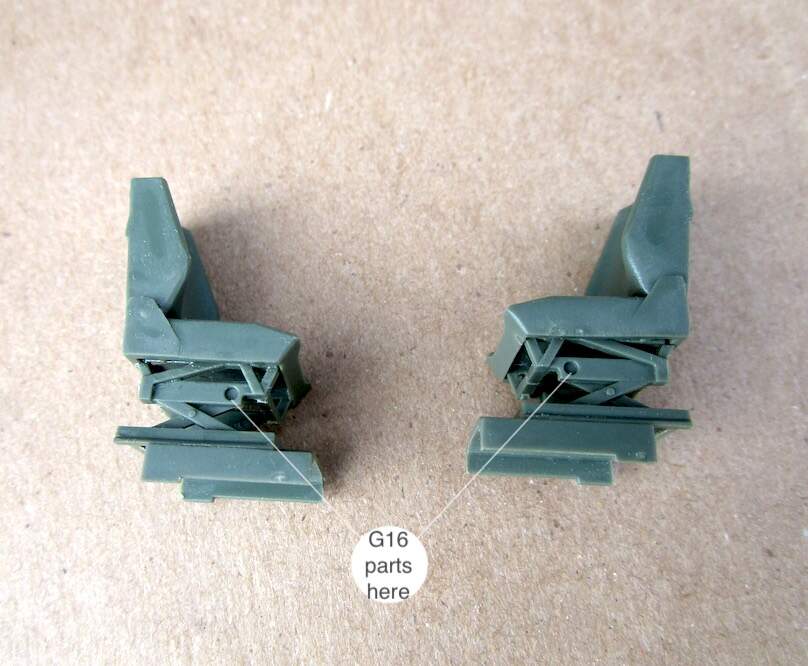
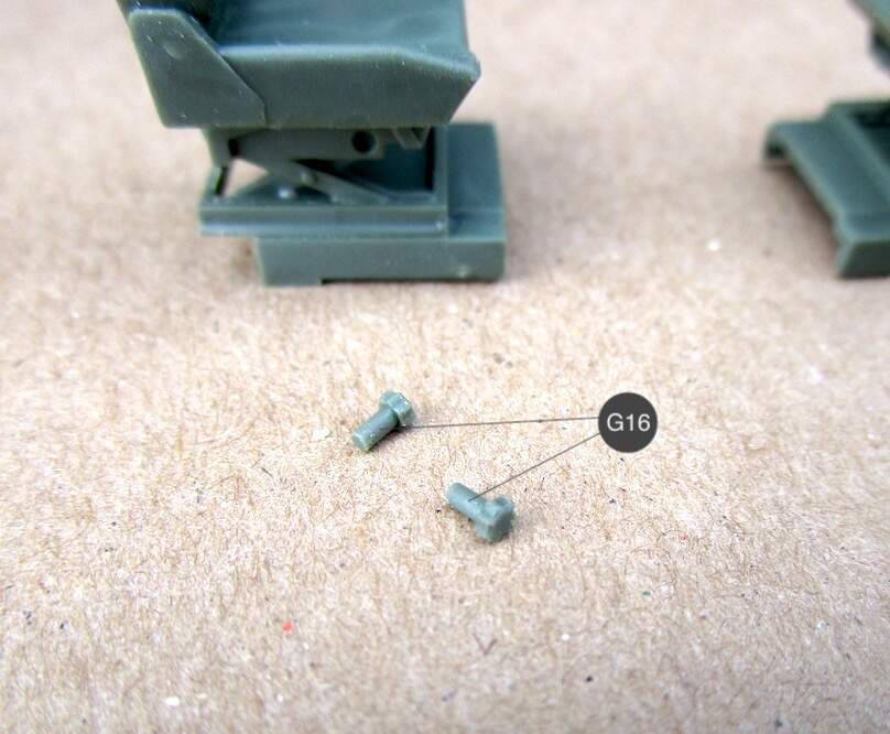
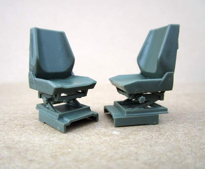
Studying the steps in building the seats and then building them are as follows. (G49) inserts into the slots and over lapse the front edge of (F6). Then the seat assembly is positioned by the front of part (G48) to the front edge of (F6). The seats assemblies are identical until the build gets to parts (G16), the seat adjustment knobs. Insert and glue one of them into the left side of one then into the right side of the other. Once this is done, the commander’s seat and the operator’s seat are established.
3 Likes
Just catched up with your build, KSO. Great work. You put a lot more effort in it with all the extra detailing than I did on my FUG. Well done so far! 
1 Like
Thank you for checking it out and for the compliment
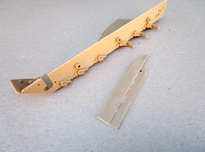
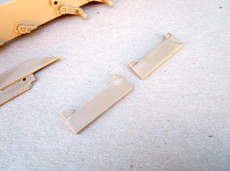
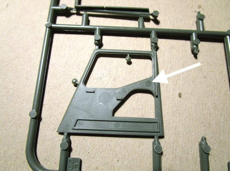
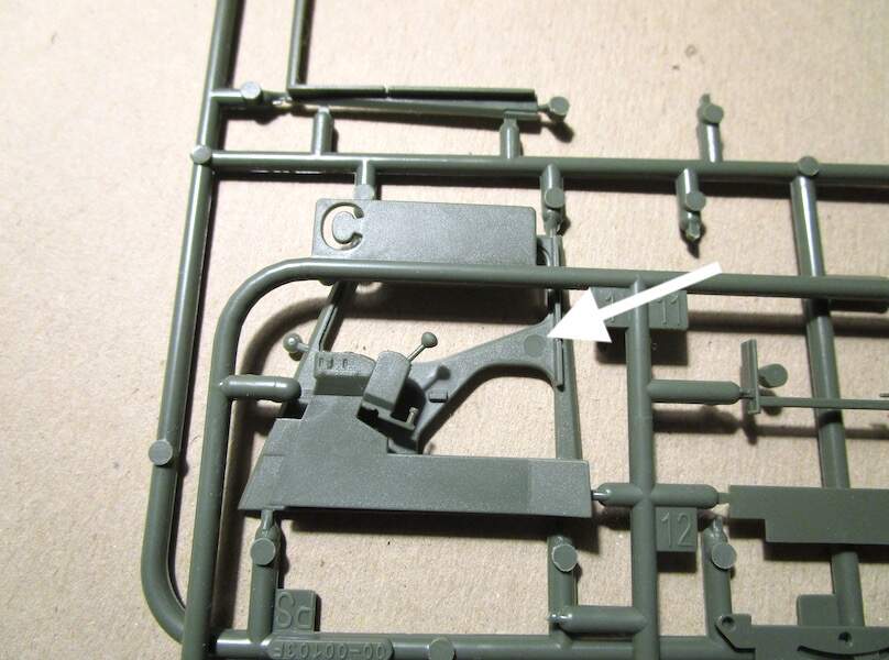
Filling ejector pin marks in the commander’s cab
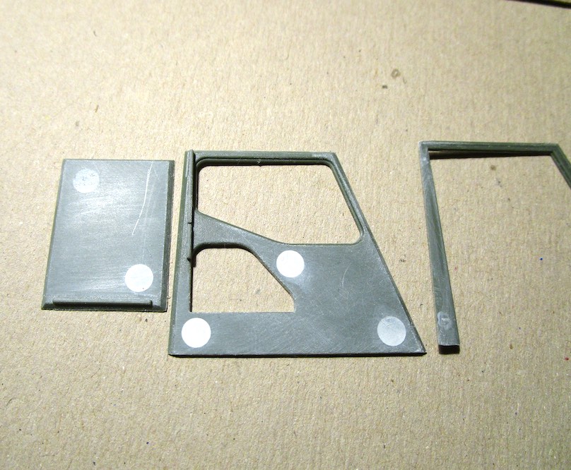
The driver’s cab has these as well but I don’t need to fill them all. One of the control panel parts covers most of it. I only need to fill one on this part, see arrow
Thanks for looking
3 Likes
K.Sp.1, amazing work.
Good detail ion the cab. How much??
1 Like