Hello everybody,
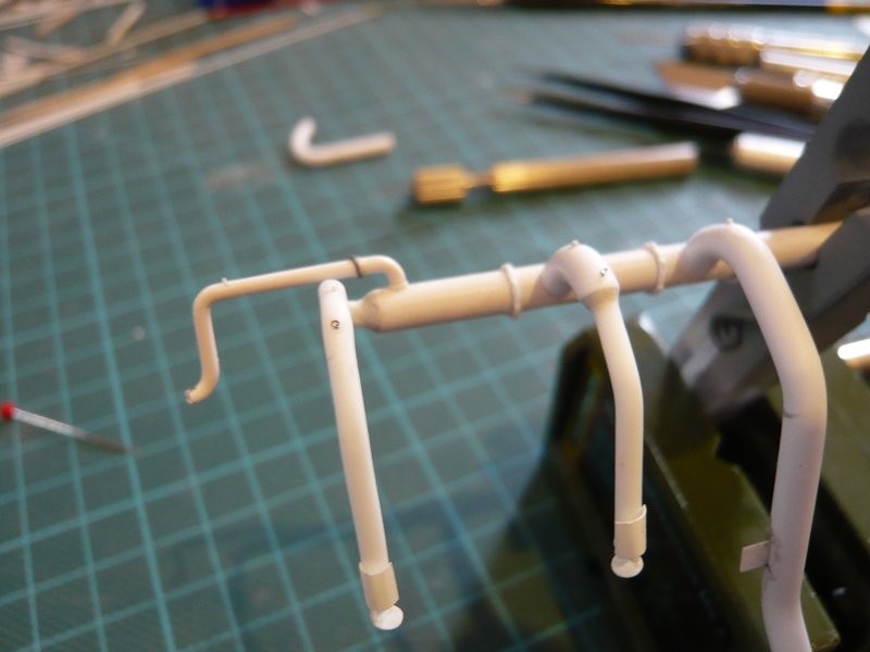
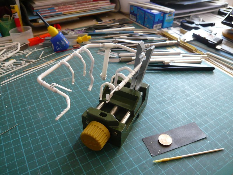
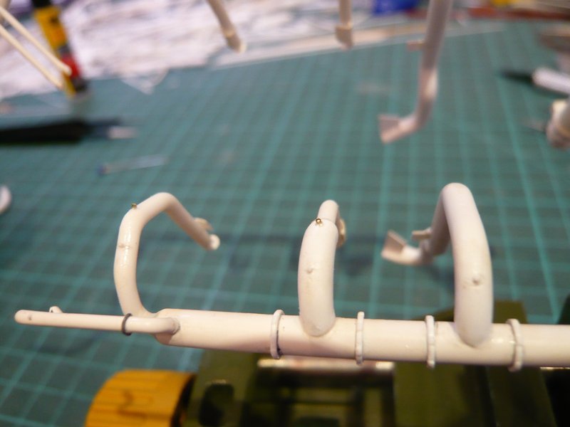
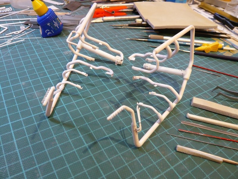
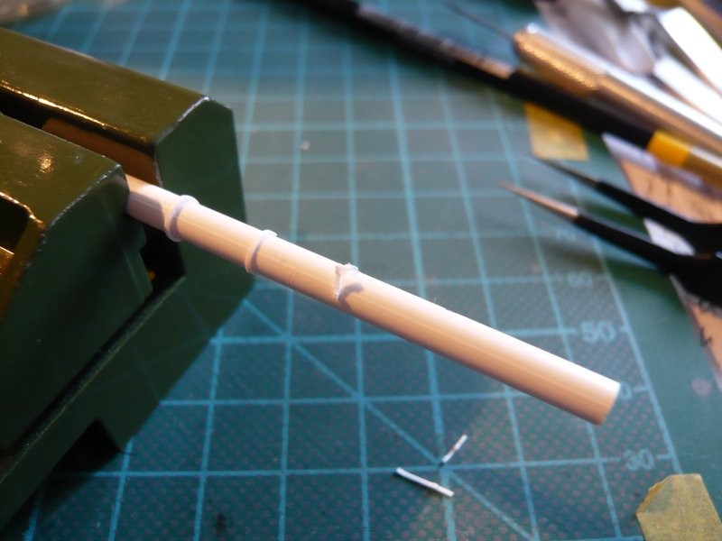
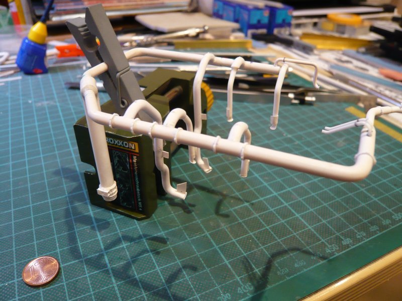
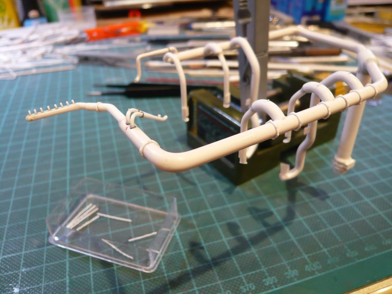
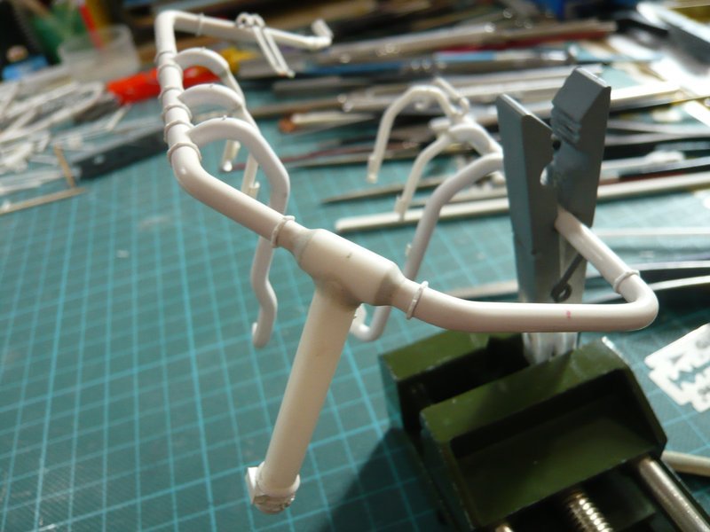
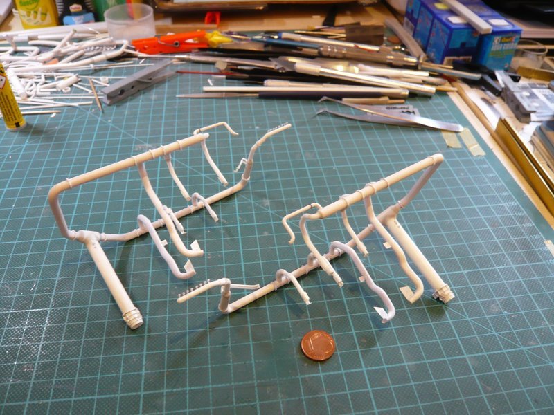
in the meantime, the modeled transitions have been carefully plastered on both pipe frames, using different tools for grinding to reach to the respective points. ![]()
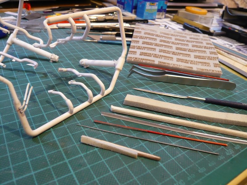
These were for the bigger roundings beside normal grinding sticks also again my handmade small sticks as well as fine files and especially Grinding sponge (Tamiya-2000). Since the grinding sponge adapts particularly well to the contours, I have glued a small sponge stick from a narrow strip and a balsa stick, with which one can carefully grind around the transition without producing unsightly nicks. ![]()
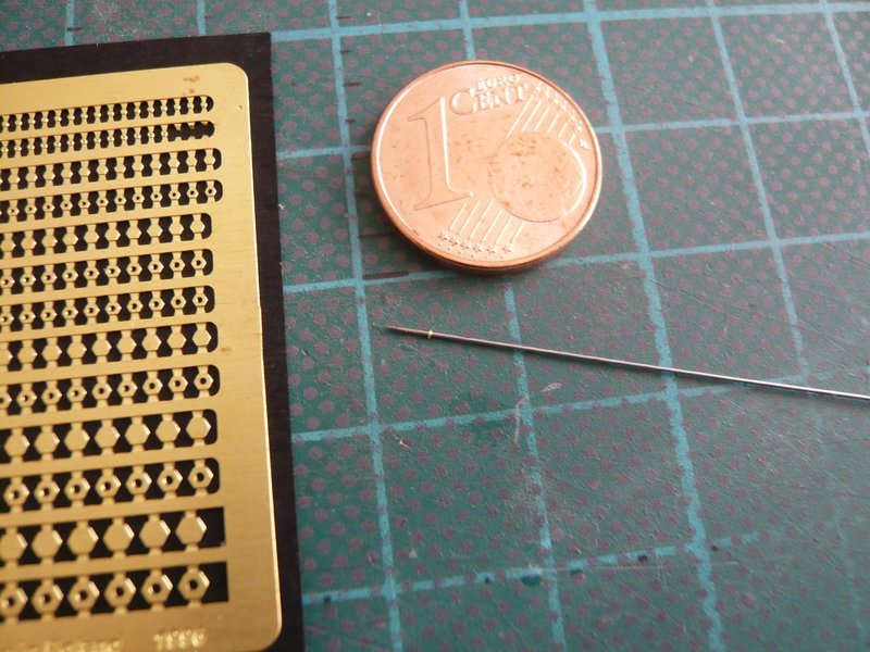
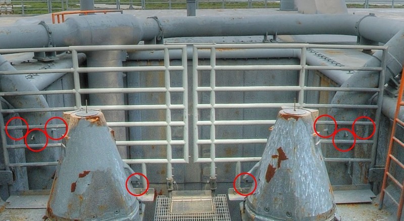
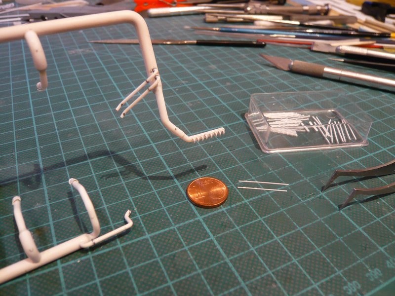
Since hardly any rework was required on the 18’’ outlets, existing unevenness were eliminated with a thin needle file (Ø 1,0 - 0,5 mm).
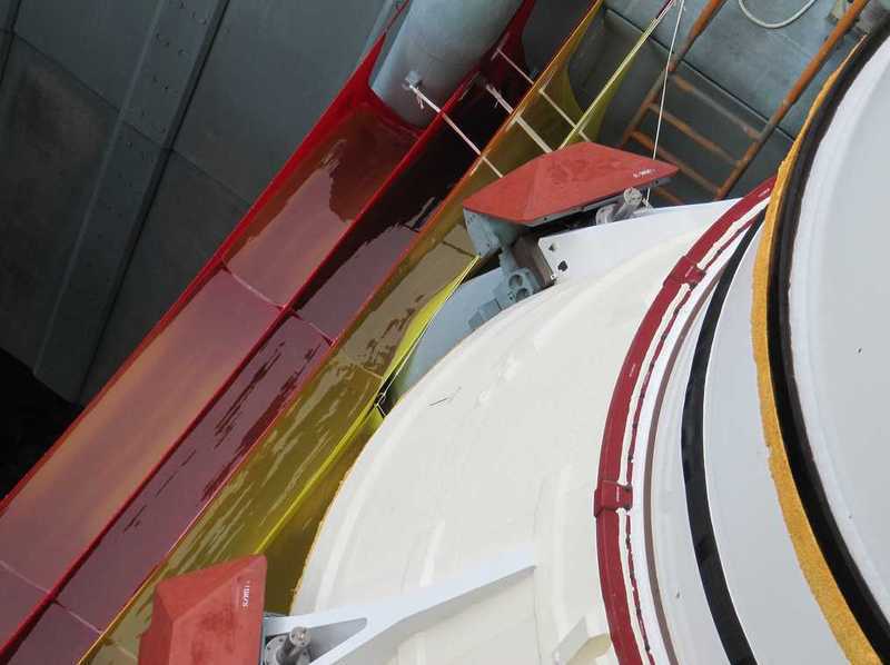
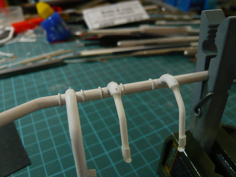
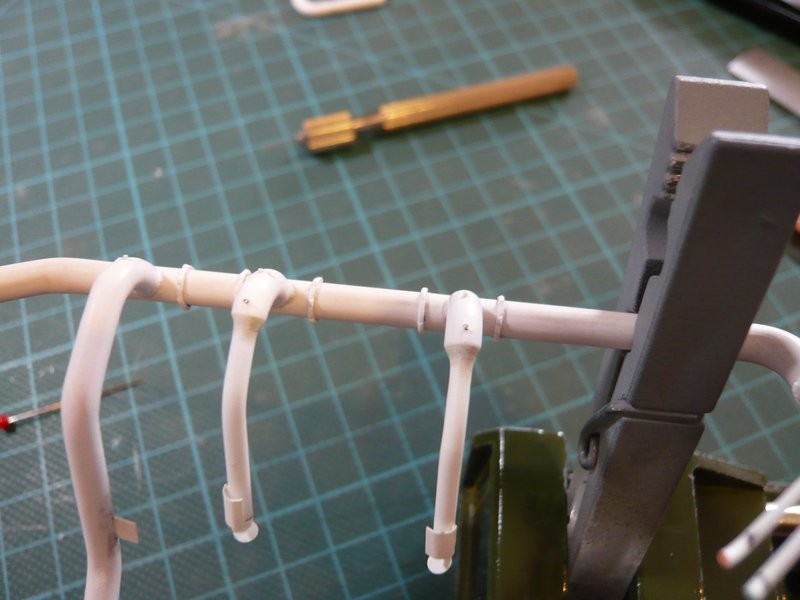
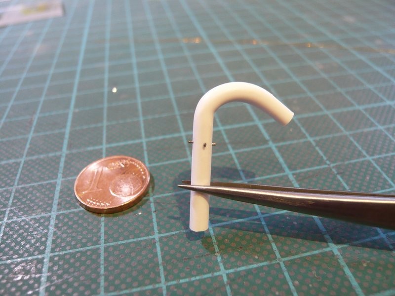
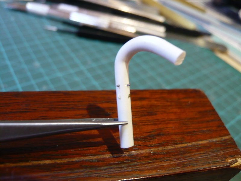
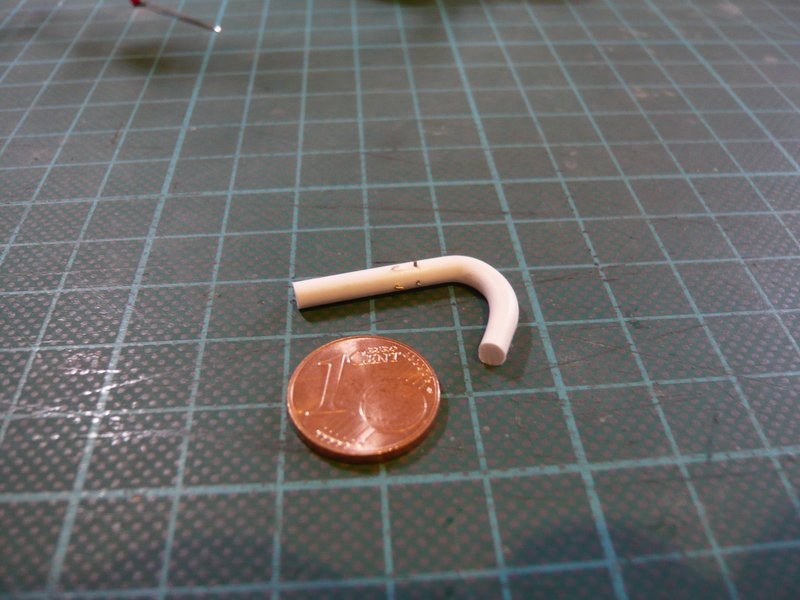
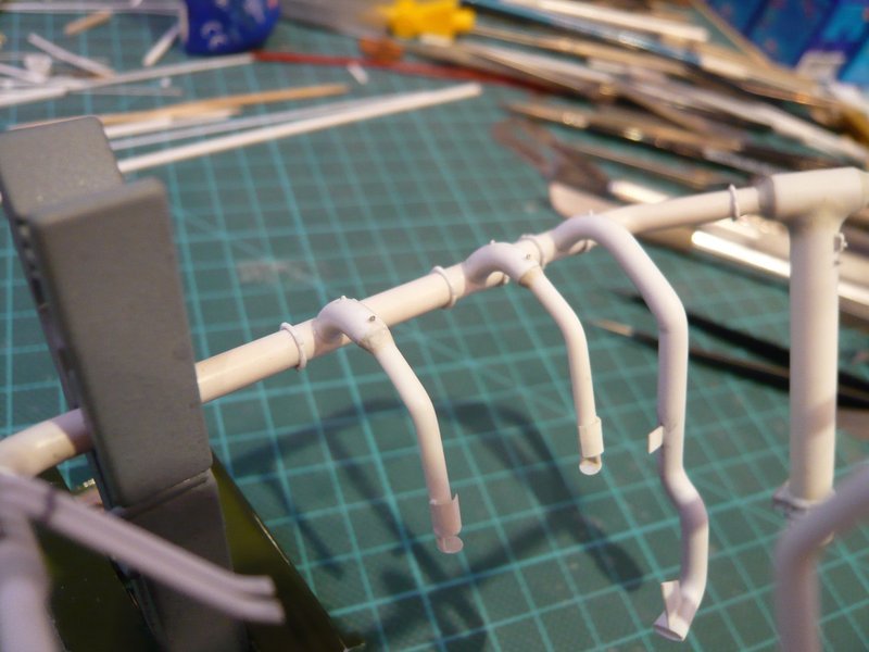
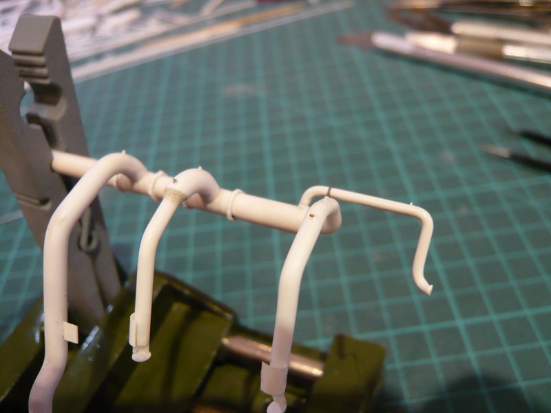
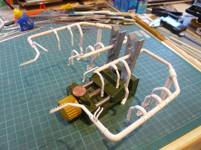
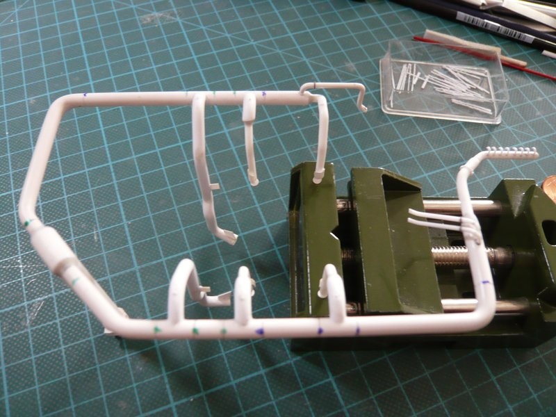
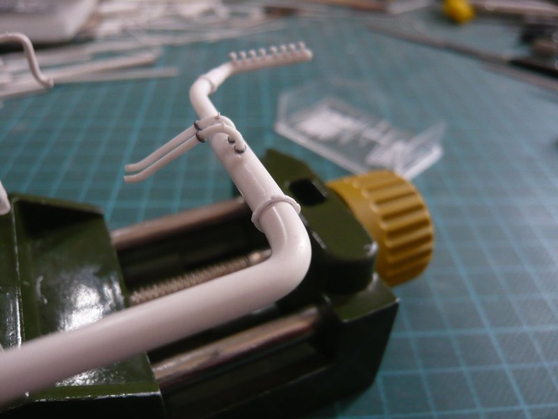
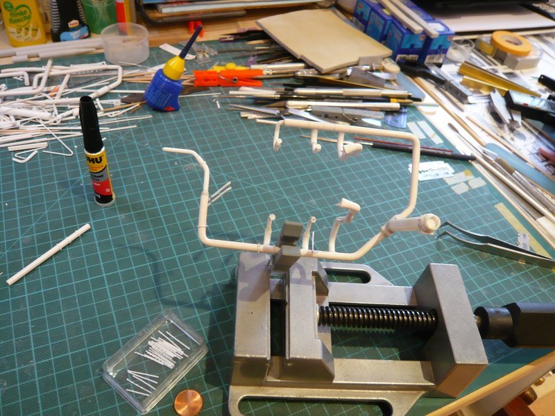
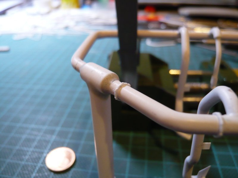
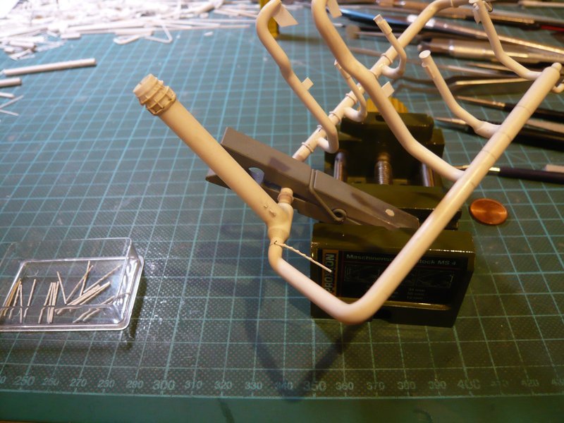
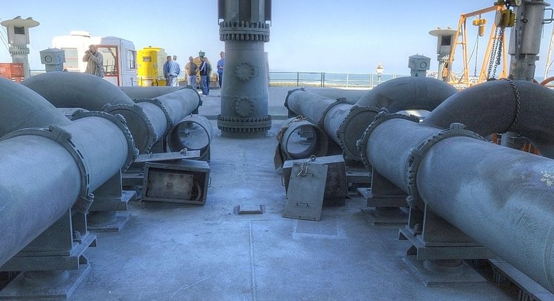
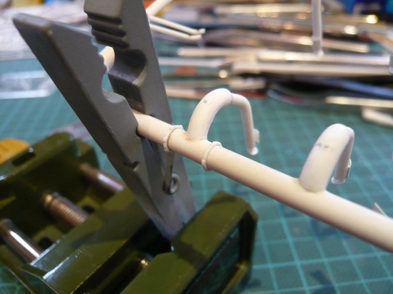
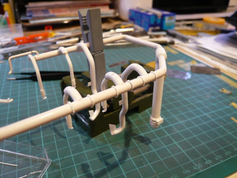
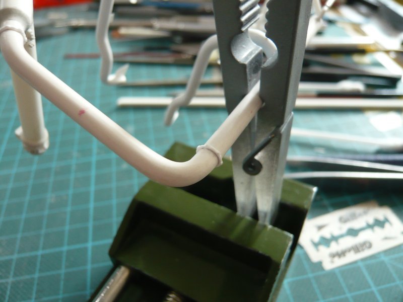
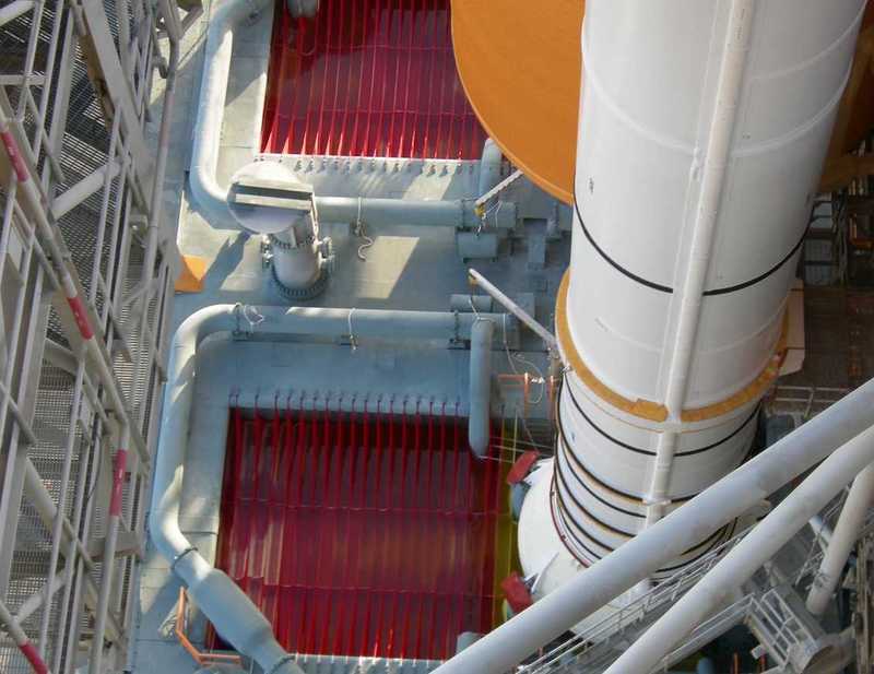
Now also the other 9’’ transition on the ring line behind the LOX-TSM could be glued, whom I had to give especially care while further handling, since the glue point with Ø 1,5 mm is highly sensitive and extremely fragile. ![]()
The thin support rods under these transitions can only be glued at the very end, because their support webs are simply too narrow and would hardly provide support. ![]()
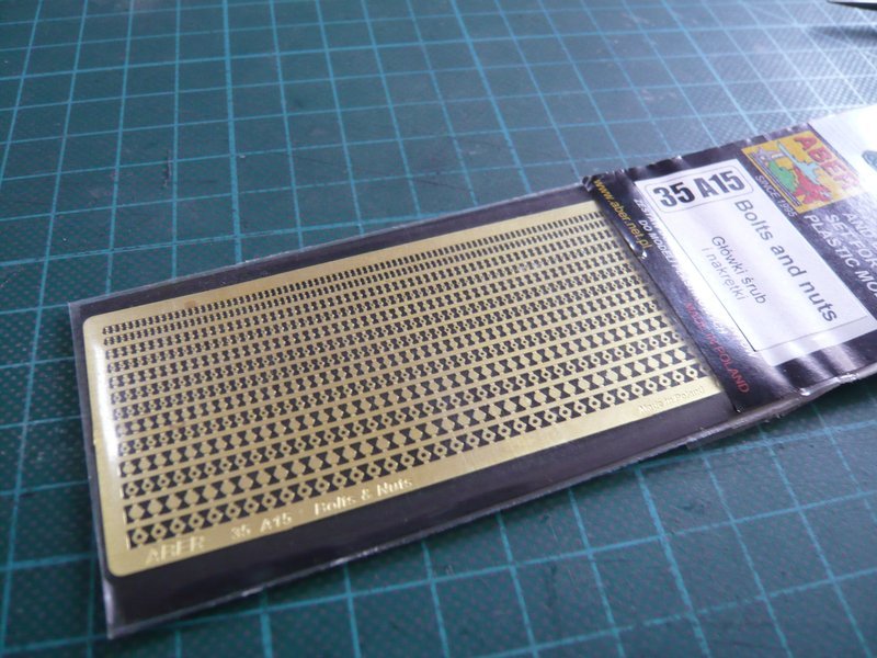
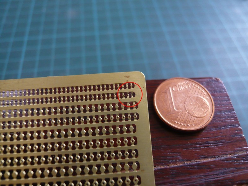
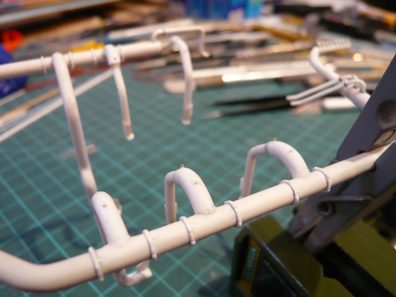
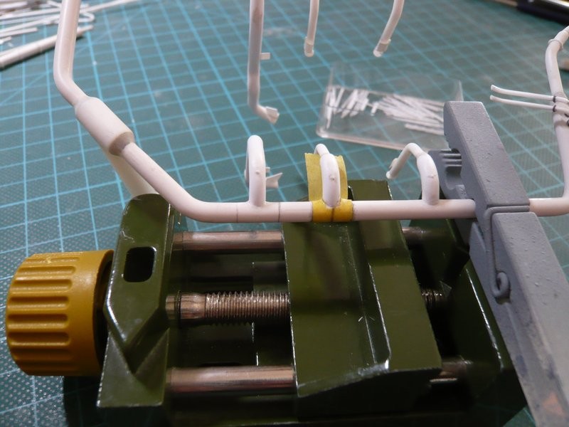
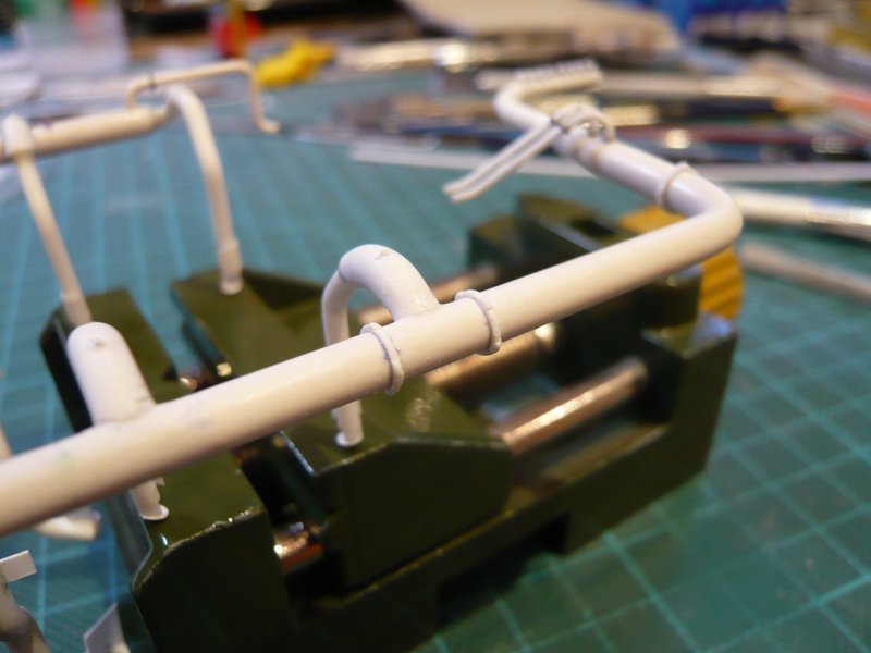
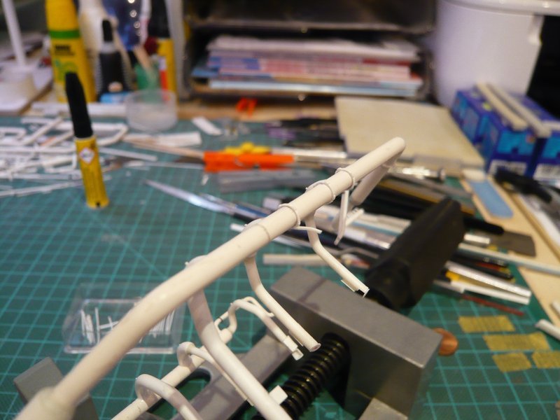
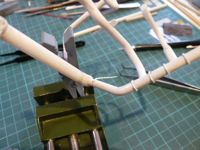
Then the other two-part clamping ring came next into line.
After I had marked the position of the screw connections with a tape strip,
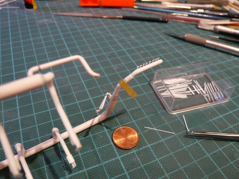
the clamping ring was glued step by step.
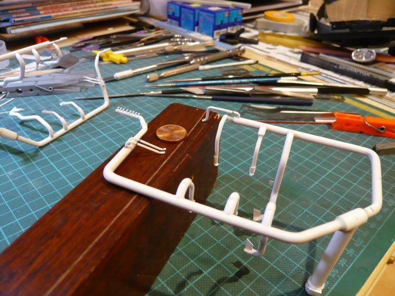

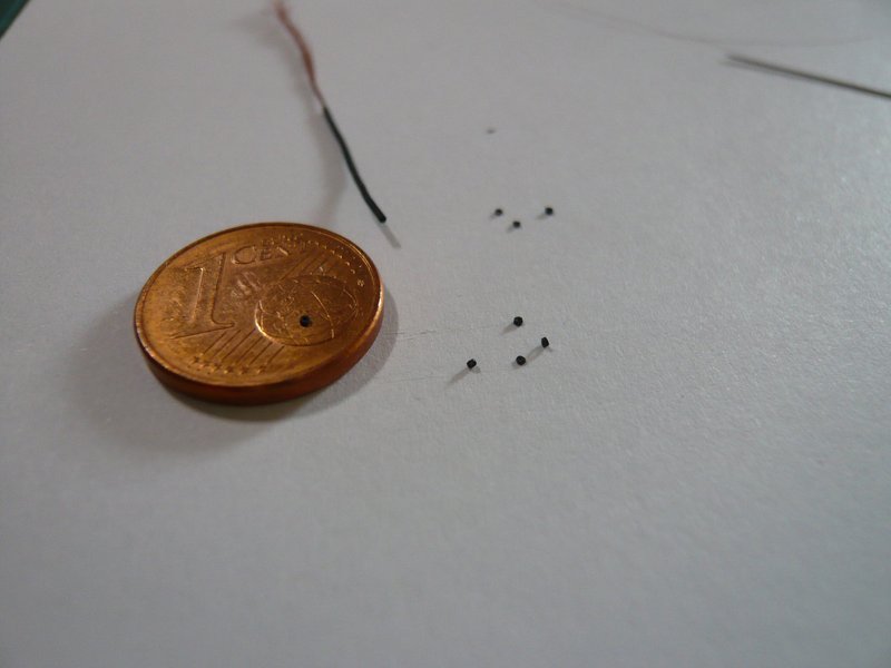
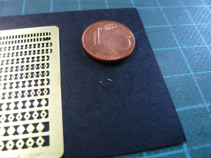
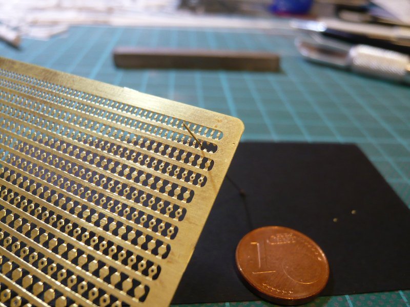
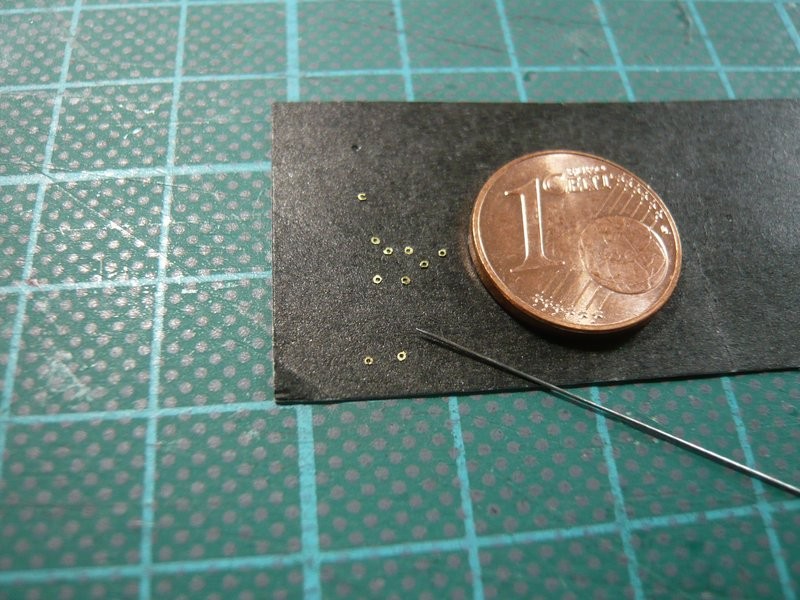
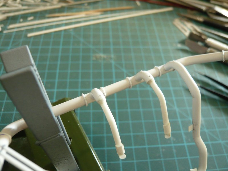
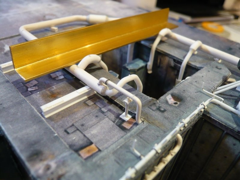
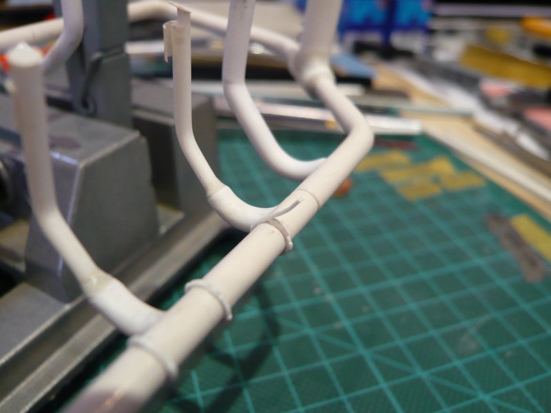
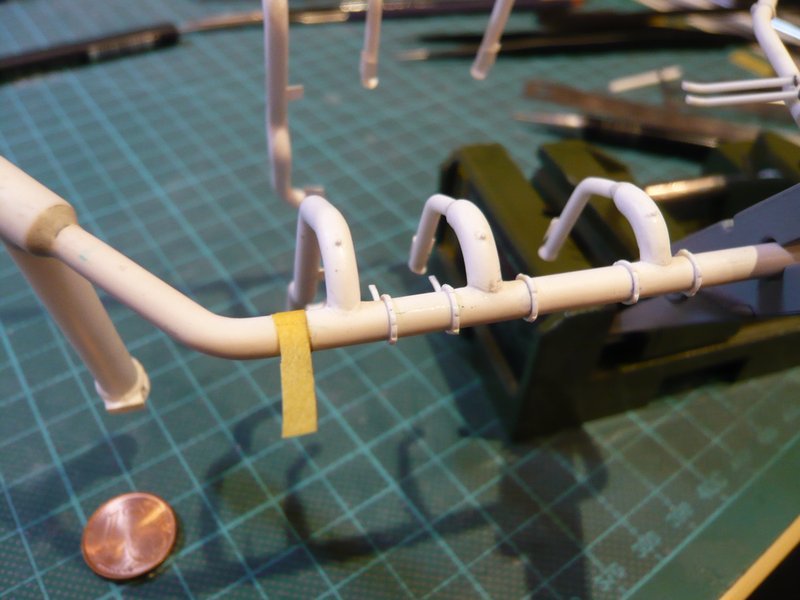
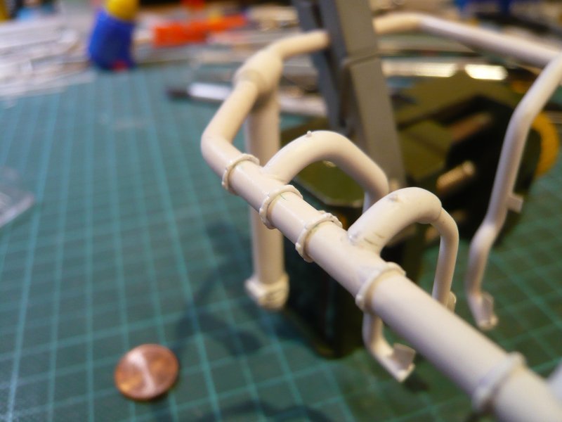
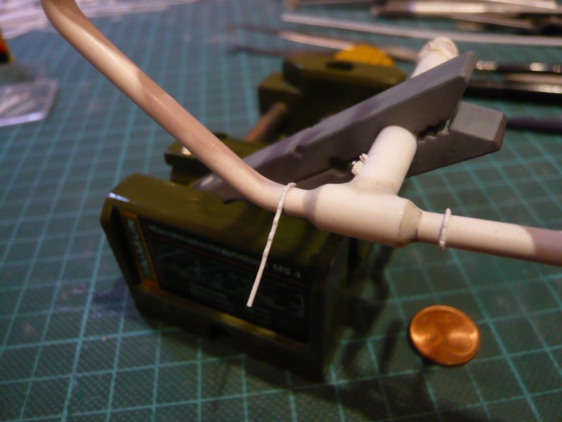
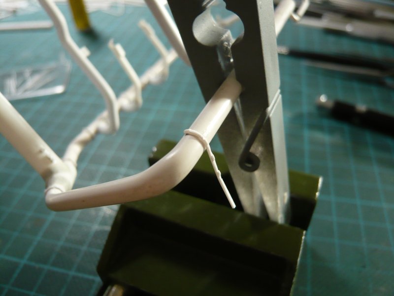
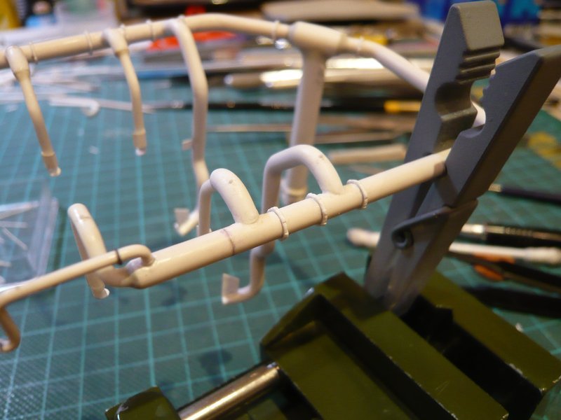
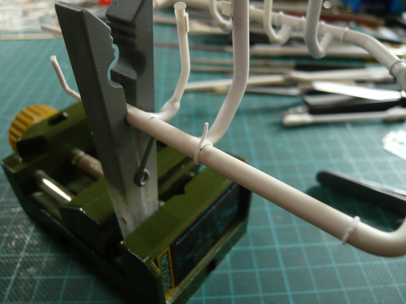
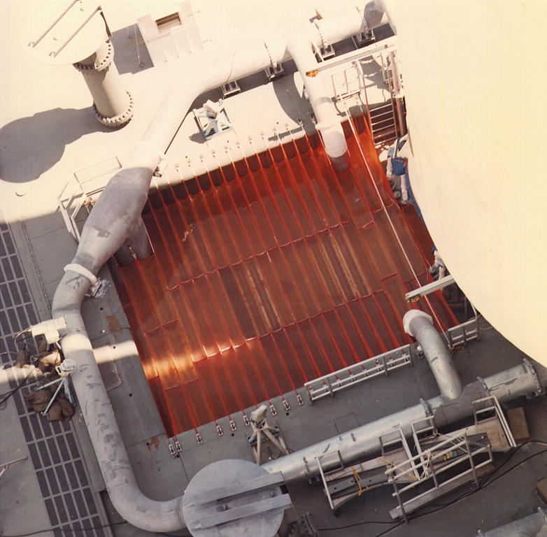
Thereby the two ring lines are now finished, so that now the 28 clamping rings can be glued, which certainly will become a stressful affair. ![]()
At first, however, the positions had to be marked, for which I have used a small tape template, which was very helpful. ![]()
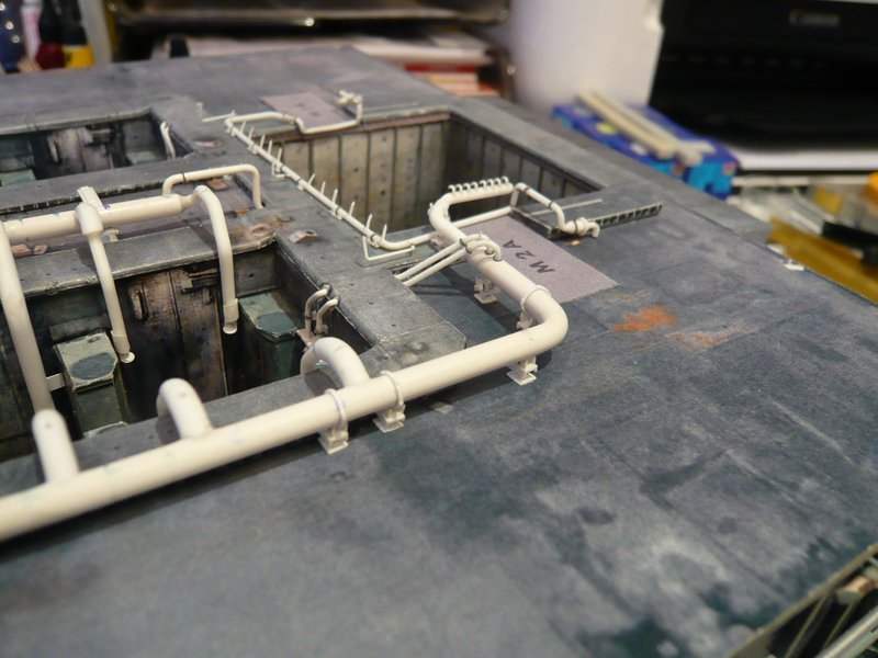
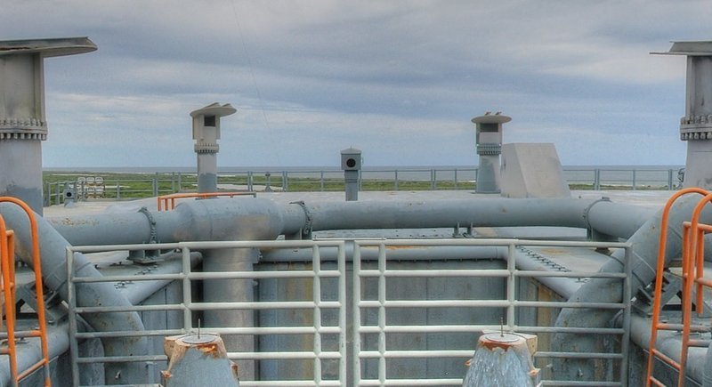
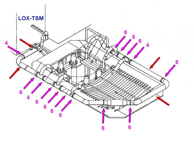
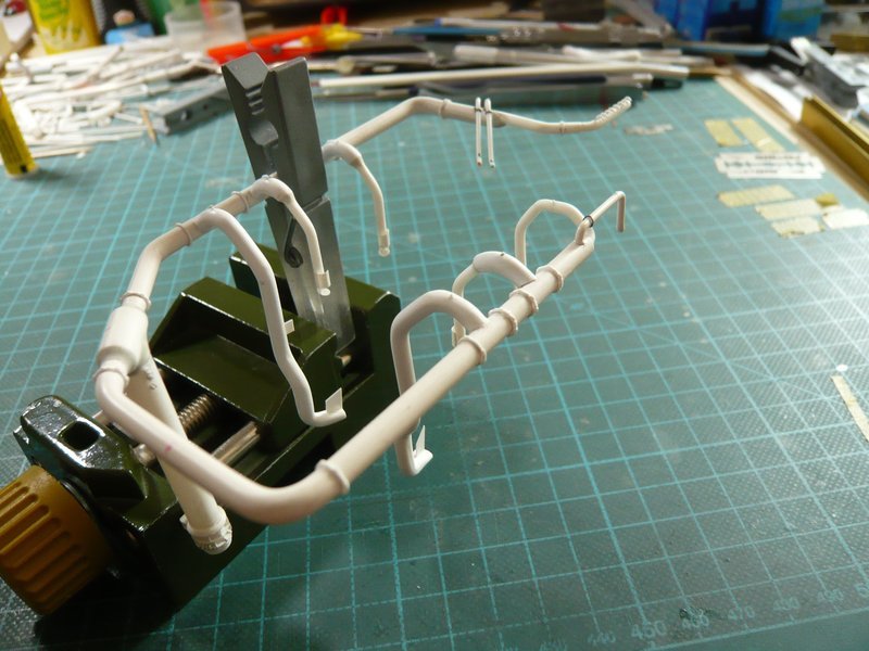
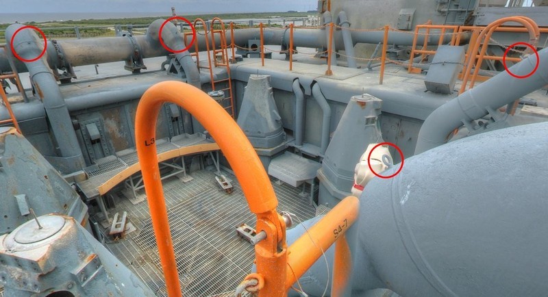
And now my drawing of the ring line behind the LH2-TSM came again into the game,
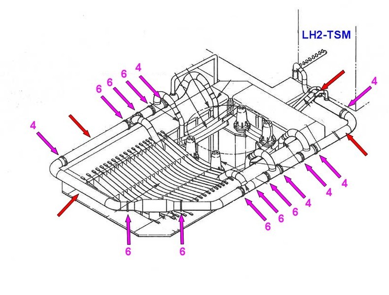
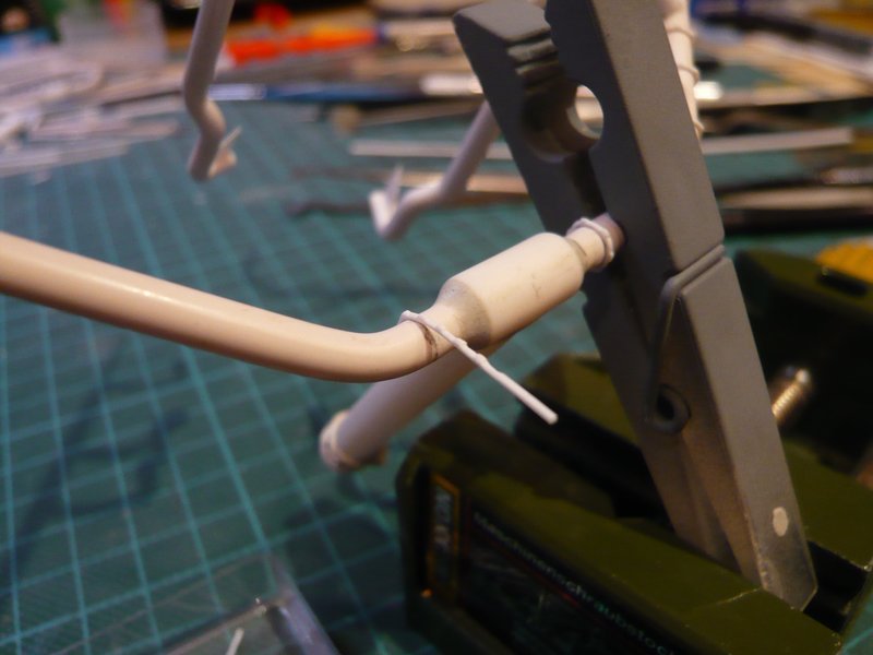
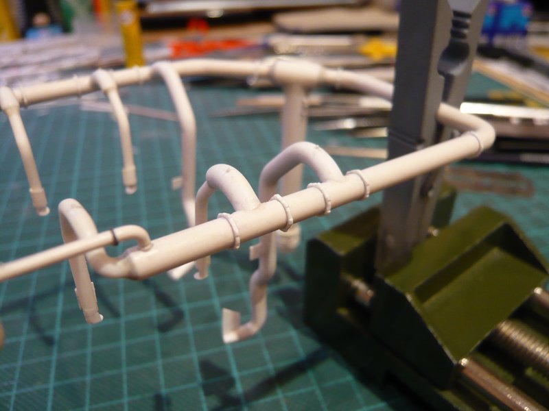
by means of which I marked the position of the six-part (green) and four-part clamping rings (blue) on the ring line, therewith nothing can get jumbled, because the arrangement of the clamping rings on the ring line behind the LOX-TSM looks a little different. ![]()
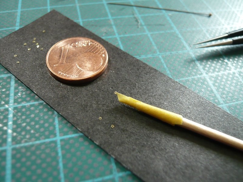
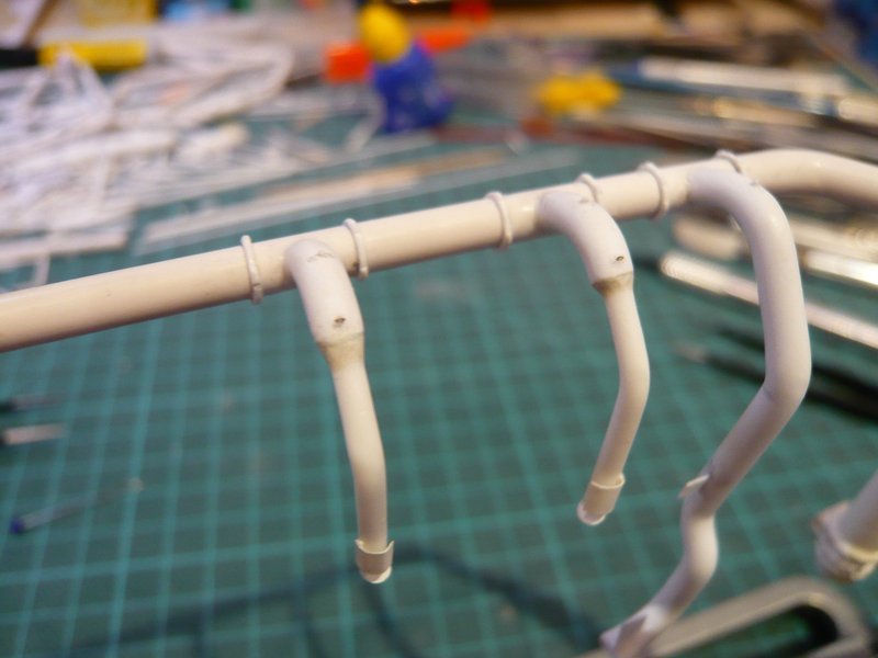
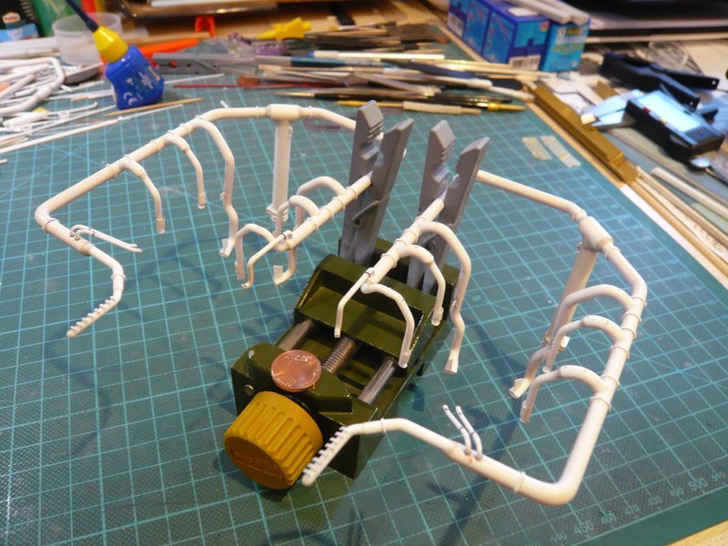
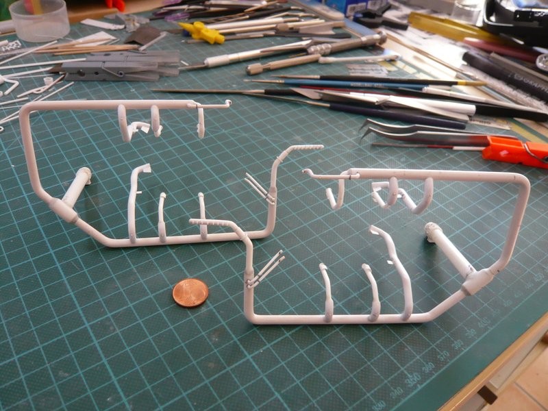
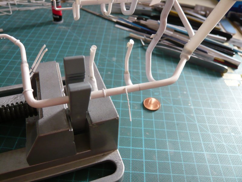
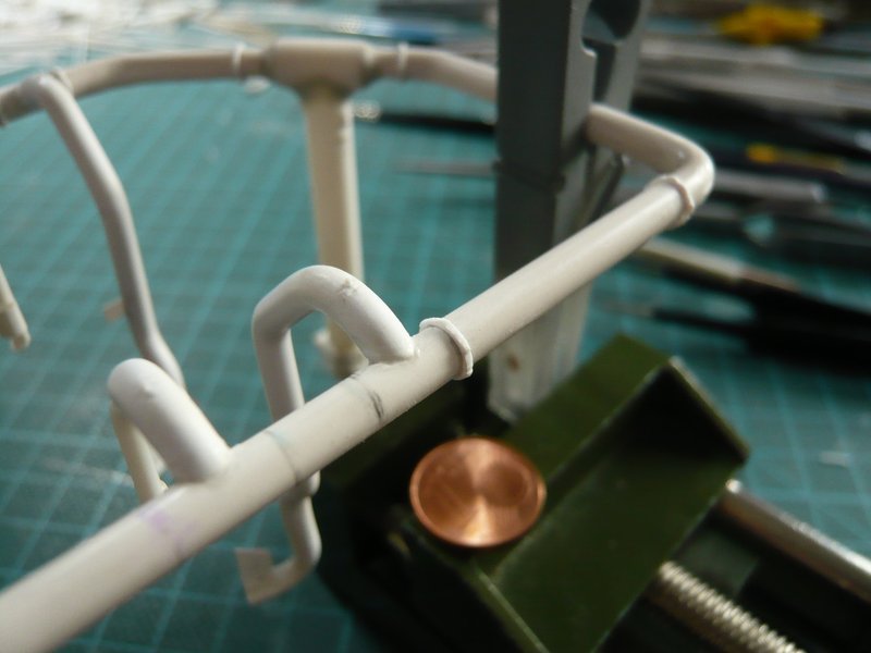
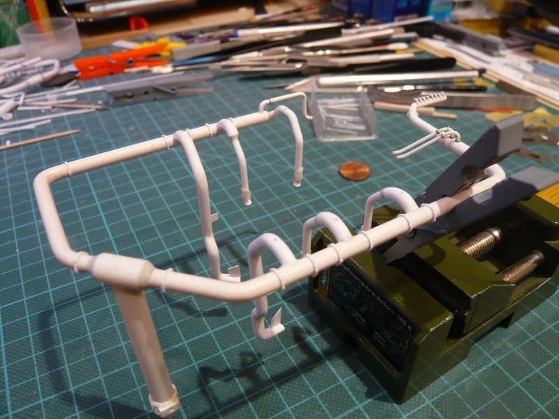
So it can now finally get started with the clamping ring orgy, of which I already a bit dread. ![]()
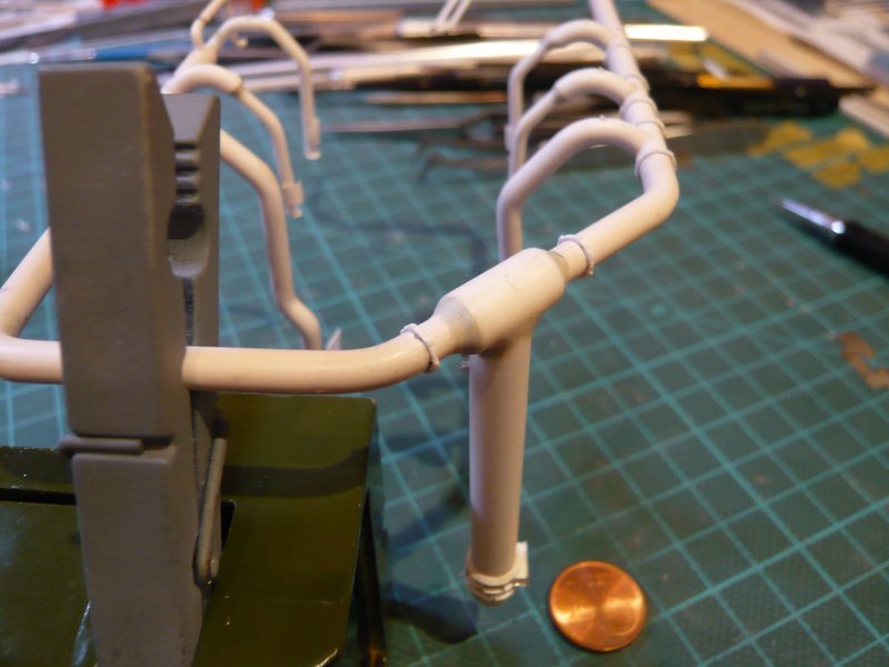
Because this time I have to go back again to the CA, because with MEK the disaster would be preprogrammed, if you can remember, long, long time ago … ![]()
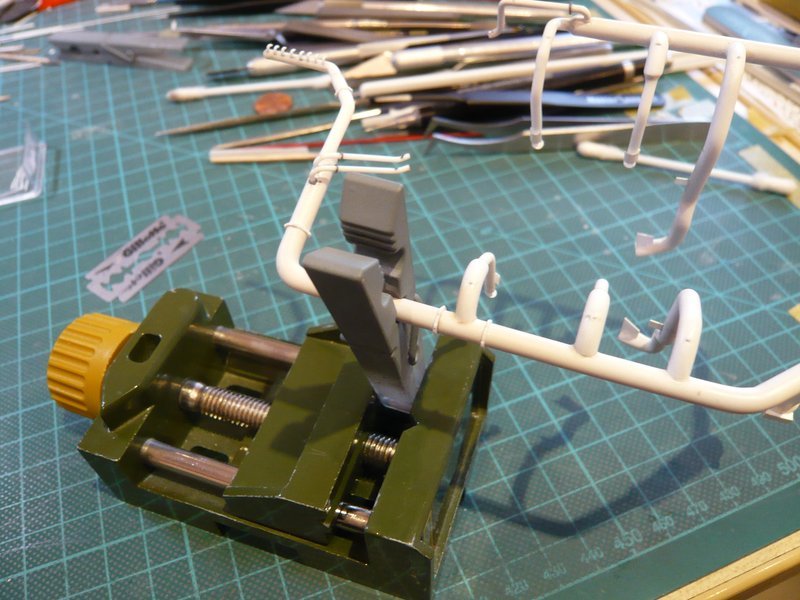
The important thing is a secure holding of the ring line, in order to be able to position the clamping rings correctly, because the first contact has to be fixed straight away, especially since correction is extremely difficult. Because if the starting point does not glue, one has to clean the glue point again, because on the old CA strangely enough no new CA glues. ![]()
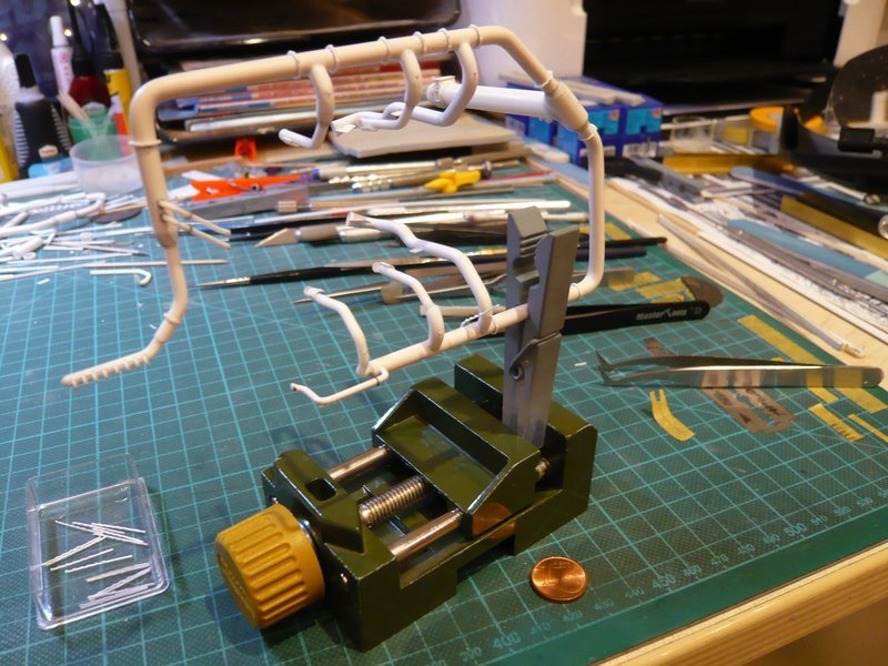
That’s it for today. Bye for now. ![]()
![]()

 because that was nevertheless also a six-part clamping ring and no four-part ring …
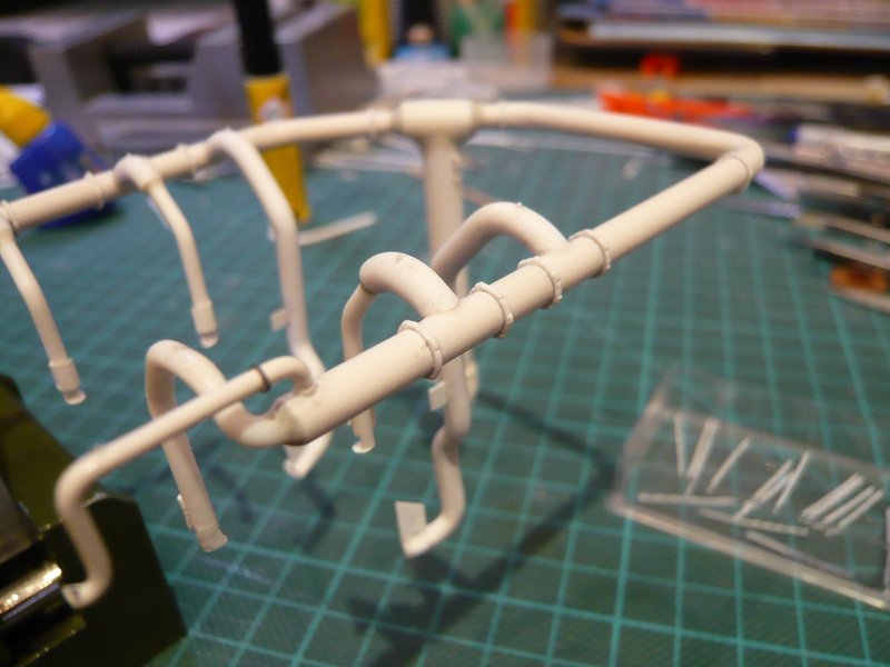

 ,
,