Space Shuttle Launch Complex 39A with Challenger STS-6 (1:144)

Hello everybody,

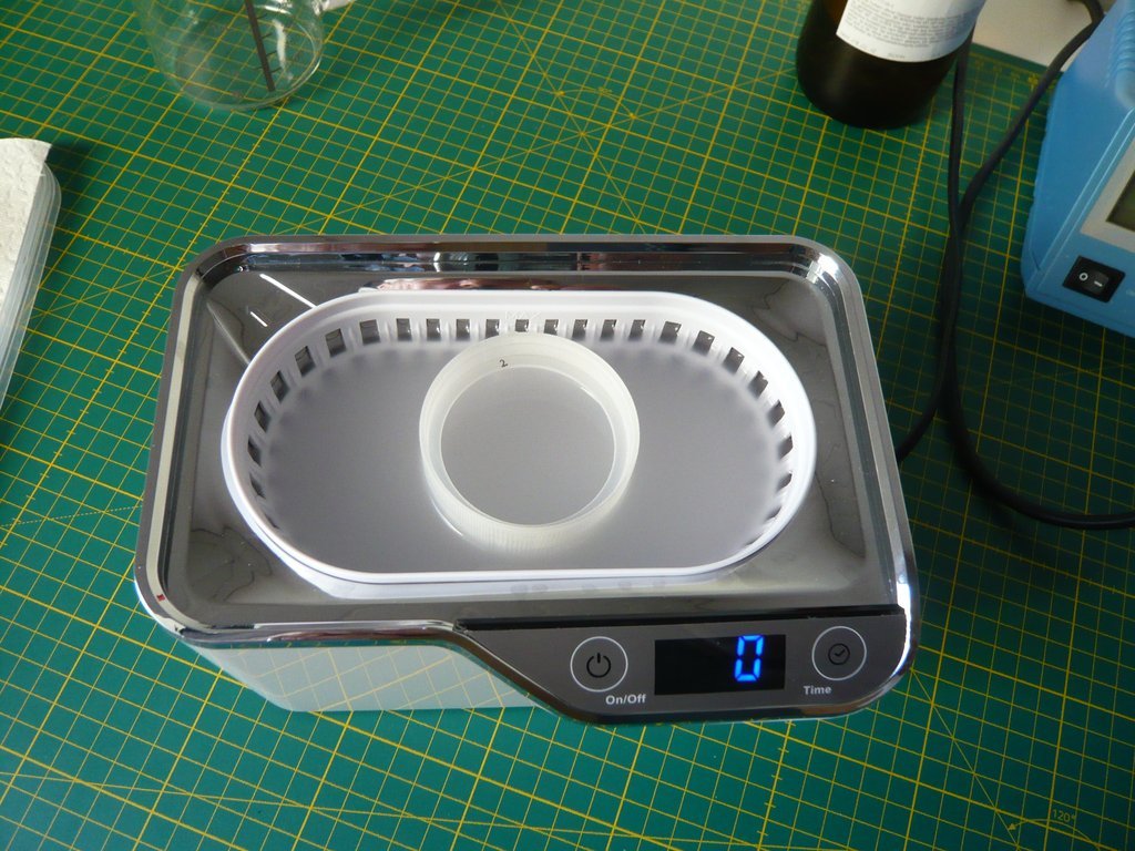
today I tested my new Ultrasonic cleaning bath. cool1

Here one can see the ultrasonic cleaning of a chain, shown in two images for comparison, in the initial state before cleaning,

and afterwards.

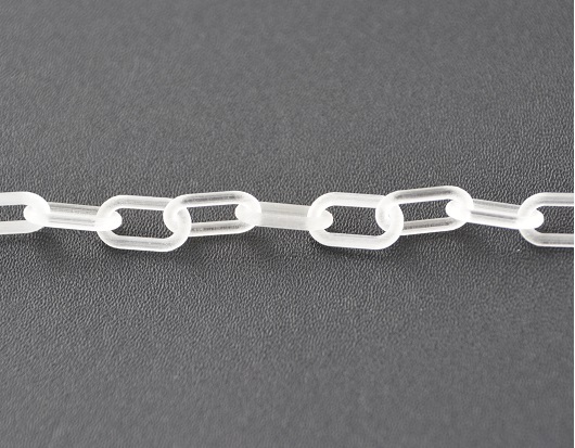
I was surprised by the time of about 4 hours, which may have been due to the selected object. https://forum.raumfahrer.net/Smileys/yabb/rolleyes.gif

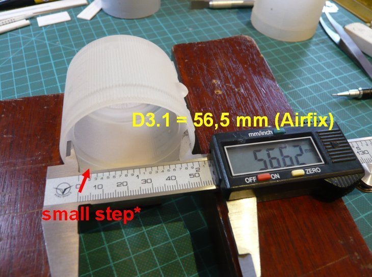
But I did not let myself be guided by that when cleaning my first two ASTC Rings (FUD), especially since the device only allows max. 10 minutes.

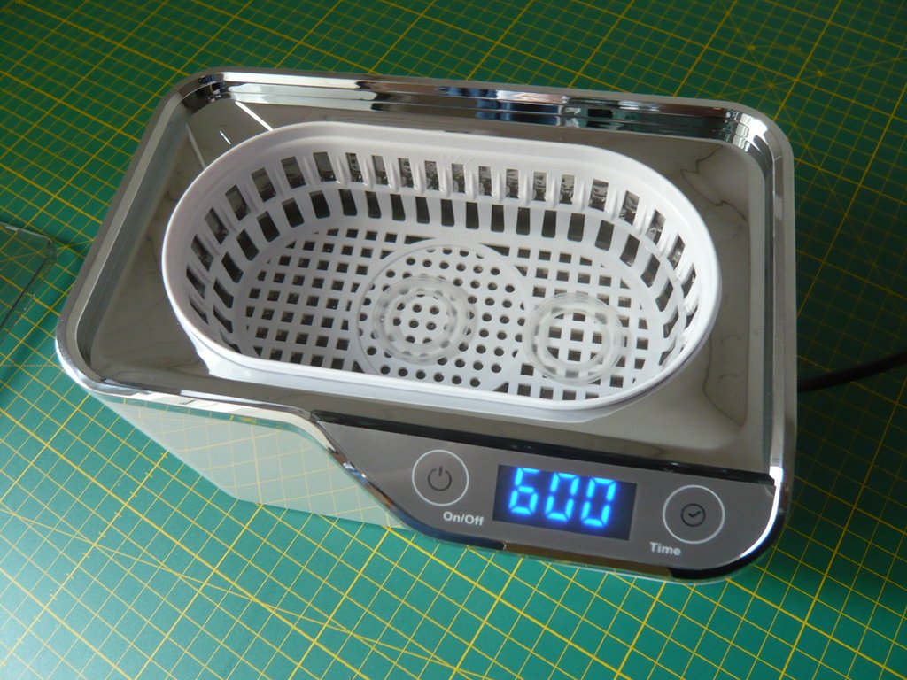
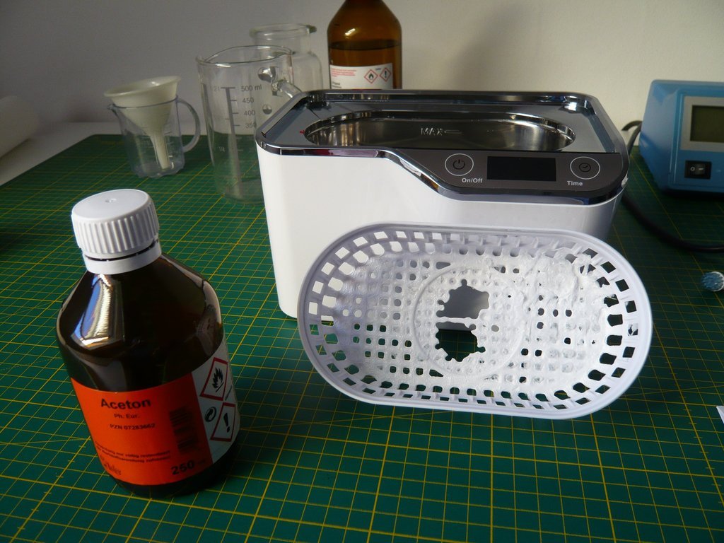
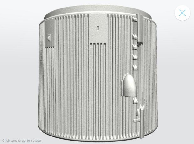
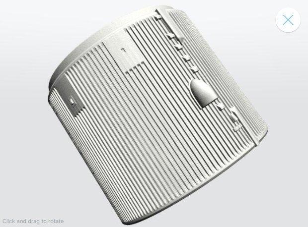
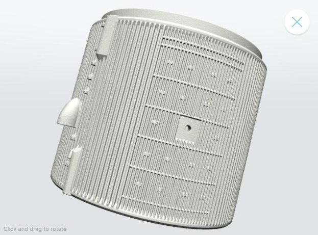
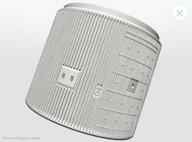
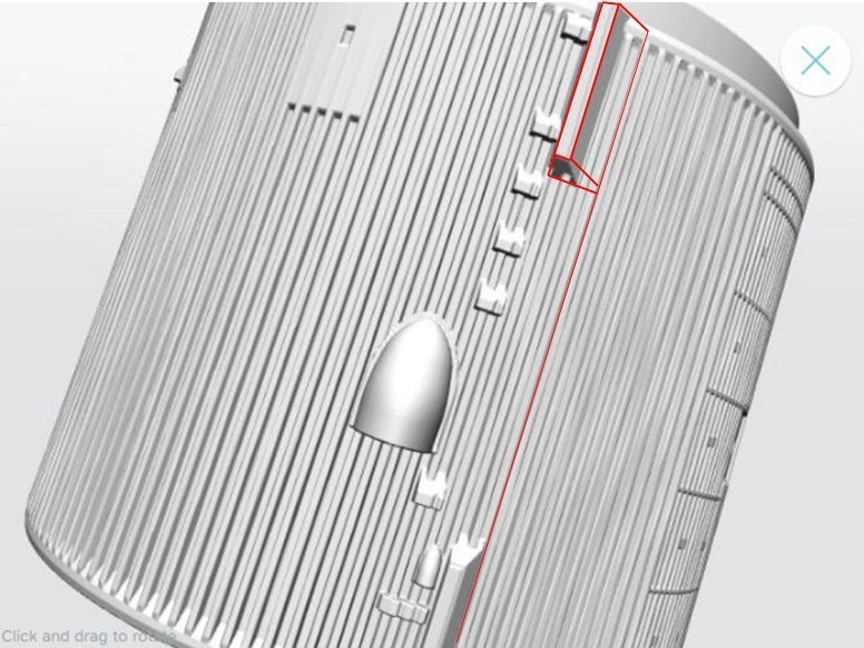
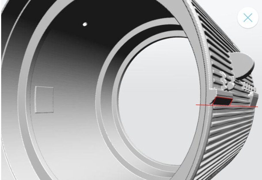
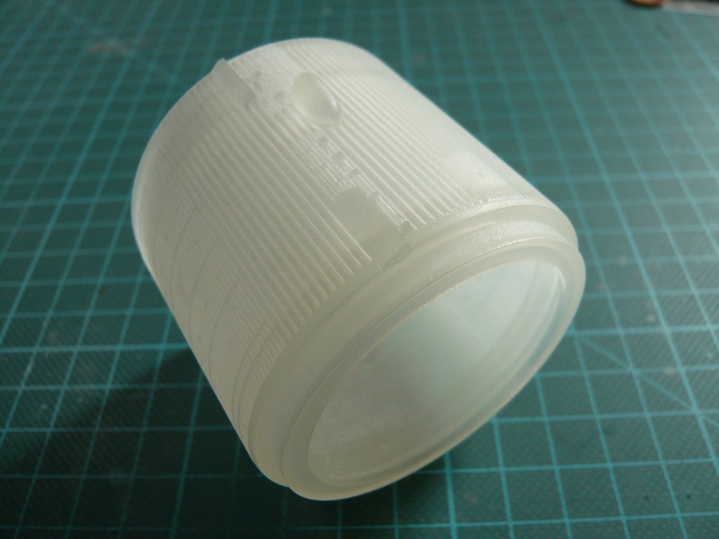
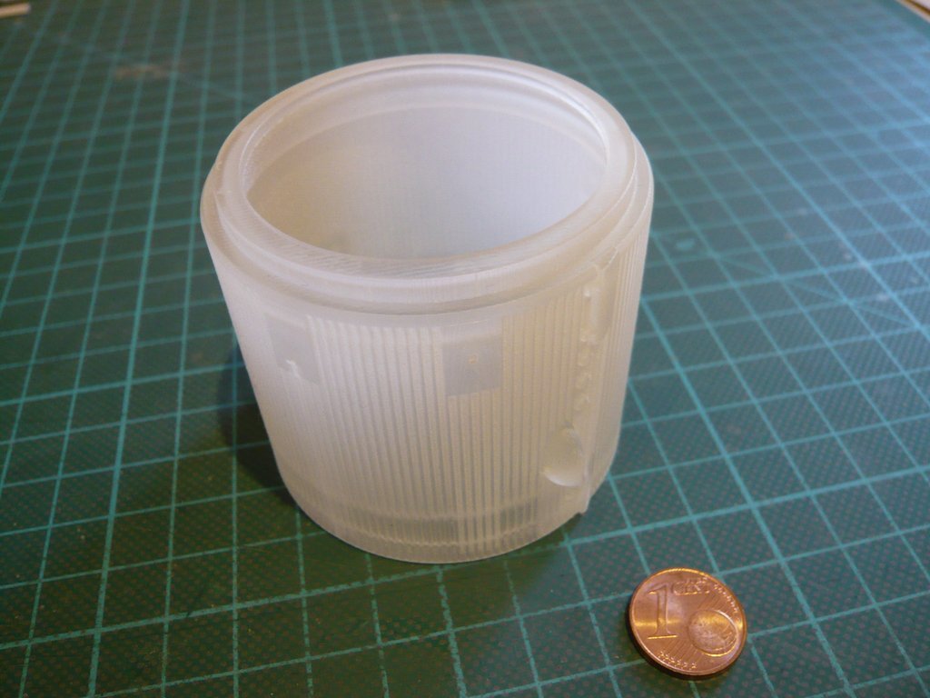
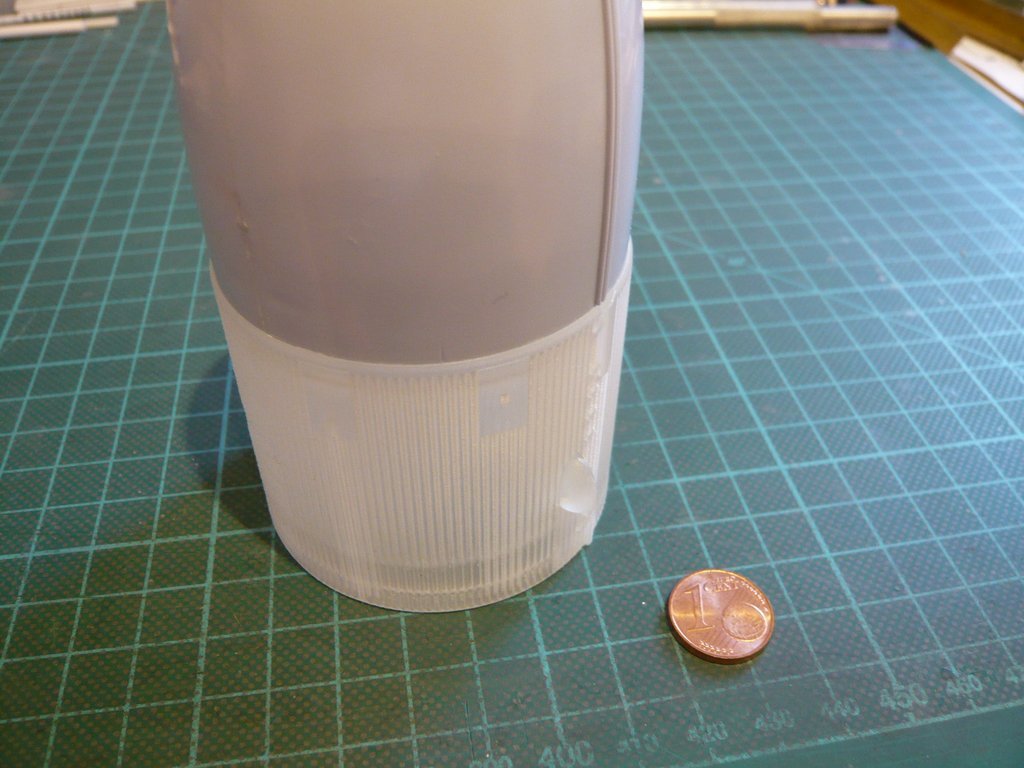
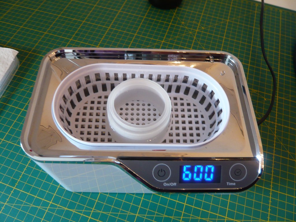
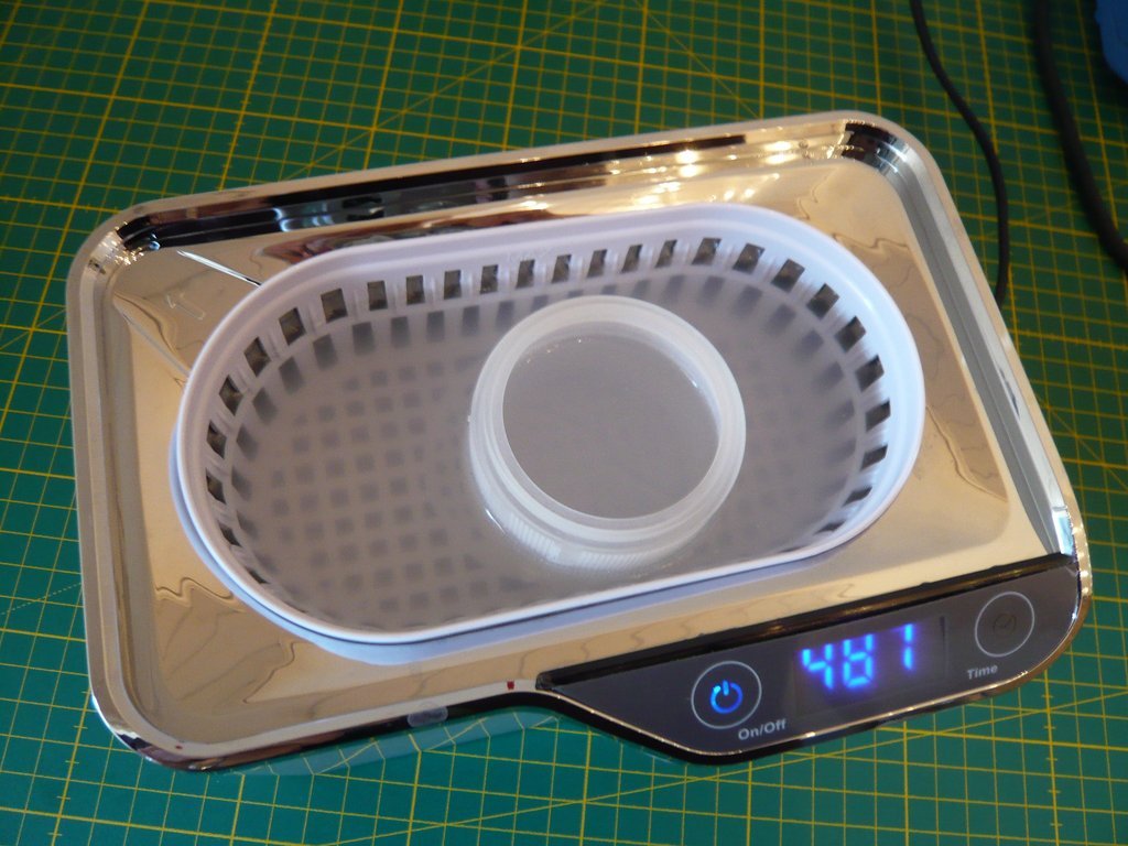
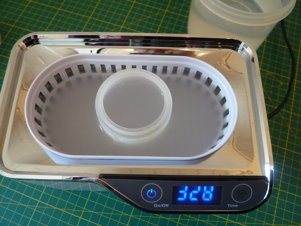
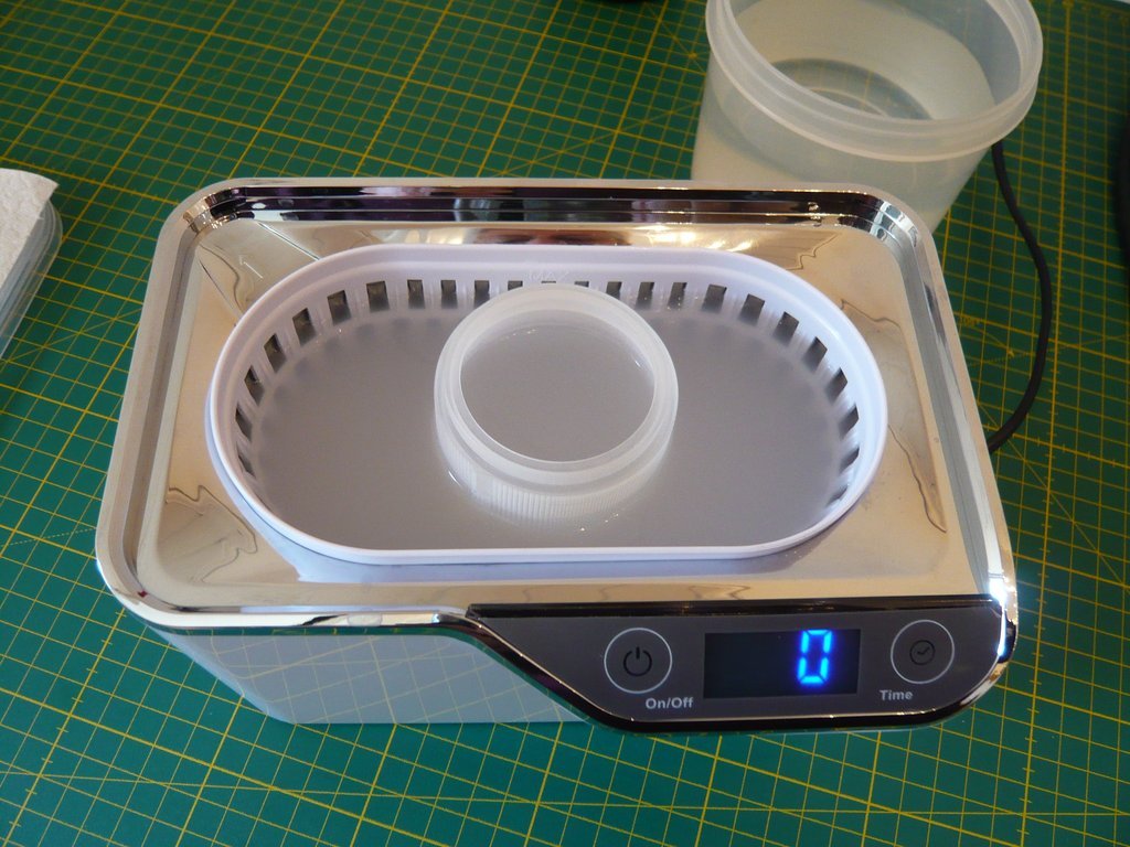
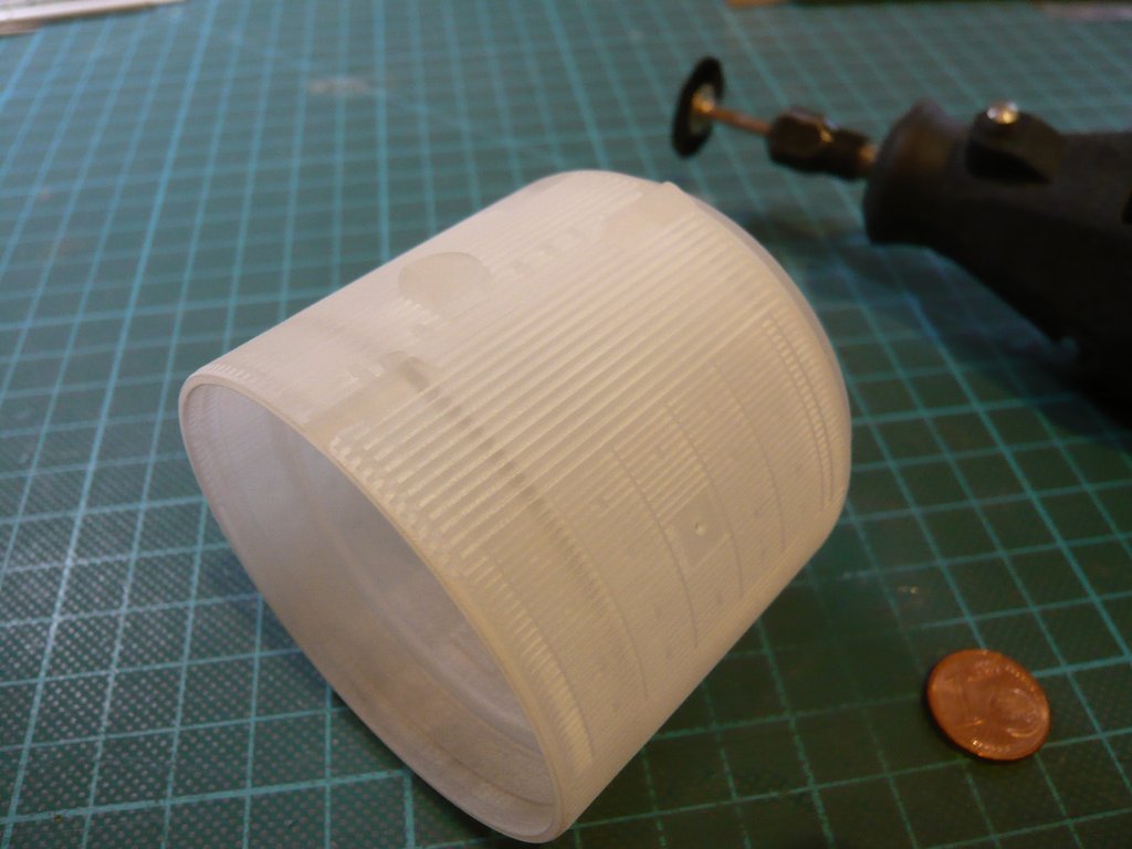
The device has 5 pre-set cleaning intervals, 90 sec., 180 sec., 300 sec., 480 sec. and 600 sec., which are automatically switched off by the timer. Obviously there is no on/off for security reasons, which I consider to be a disadvantage, especially when I think of cleaning the Intertank with its lots of fine grooves, which will certainly have to run for a longer time.

That’s why I asked the manufacturer if there is no other option than having to restart the timer over and over again.

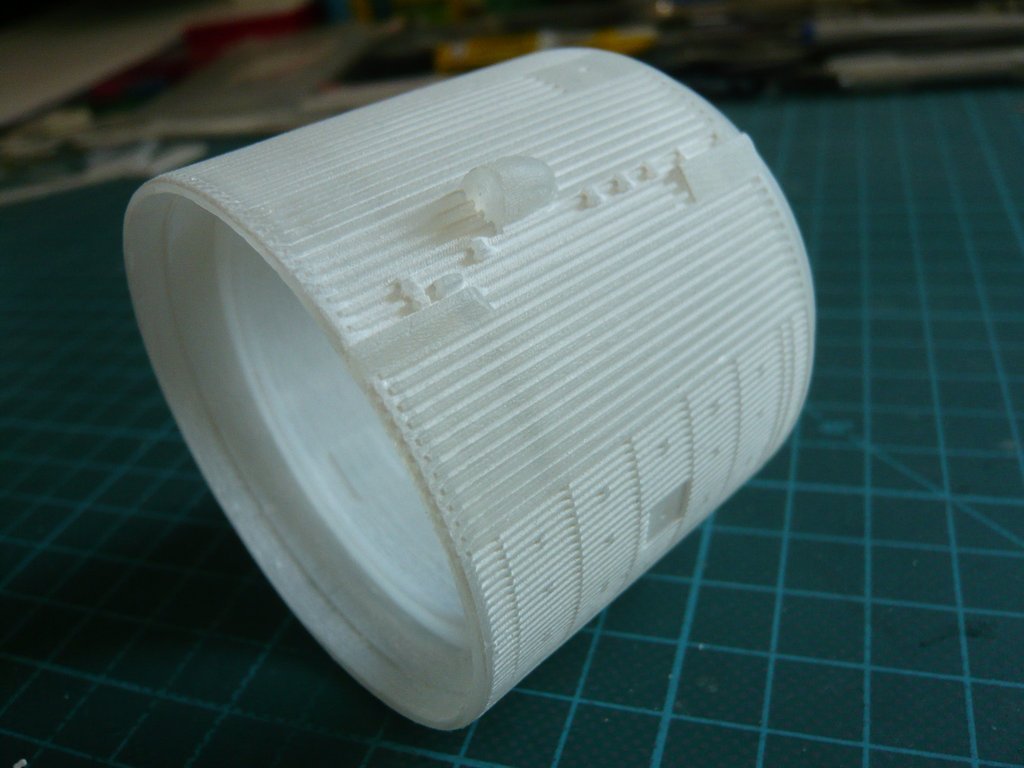
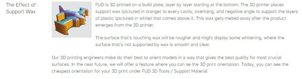
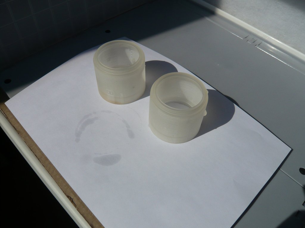
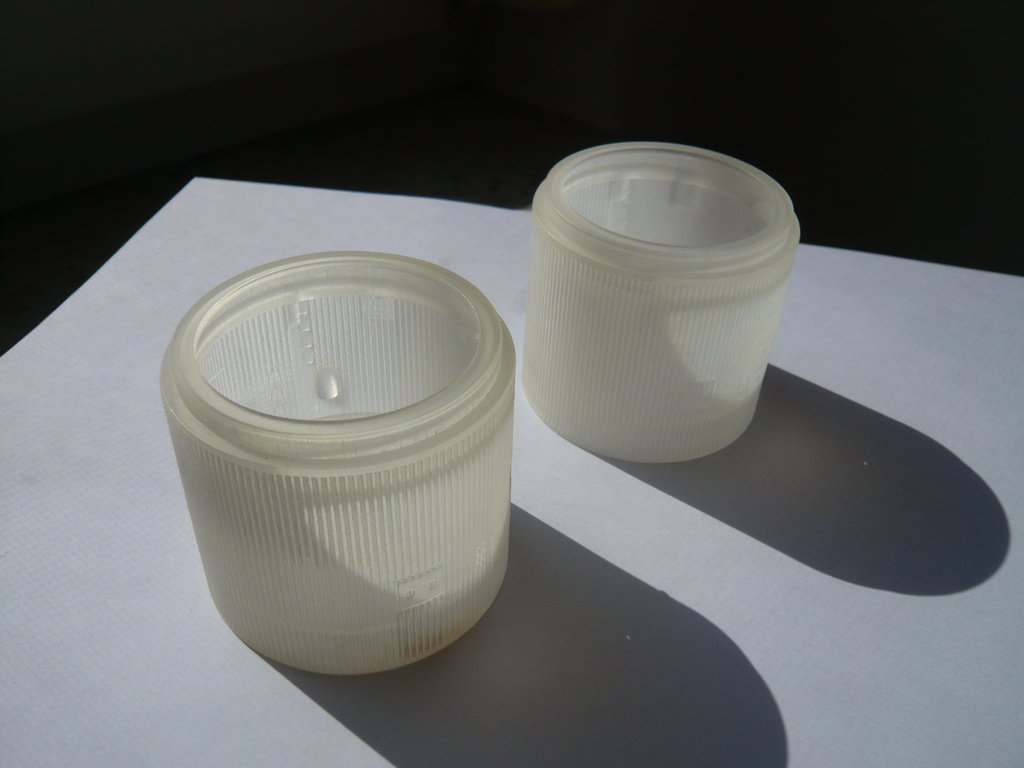
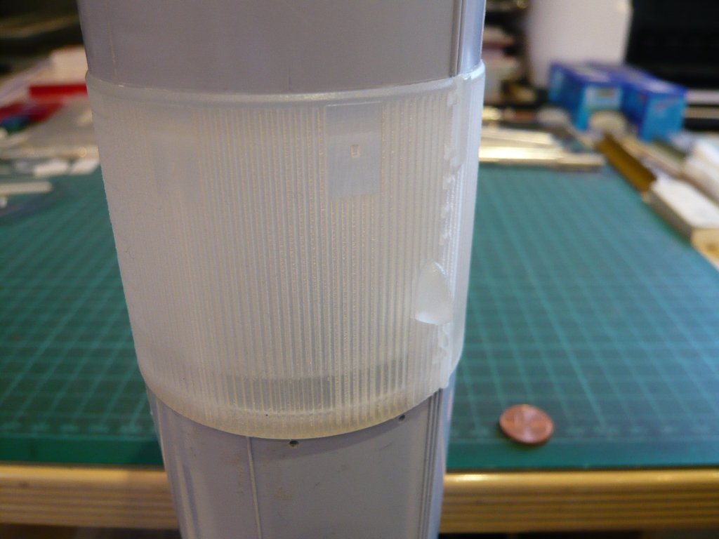
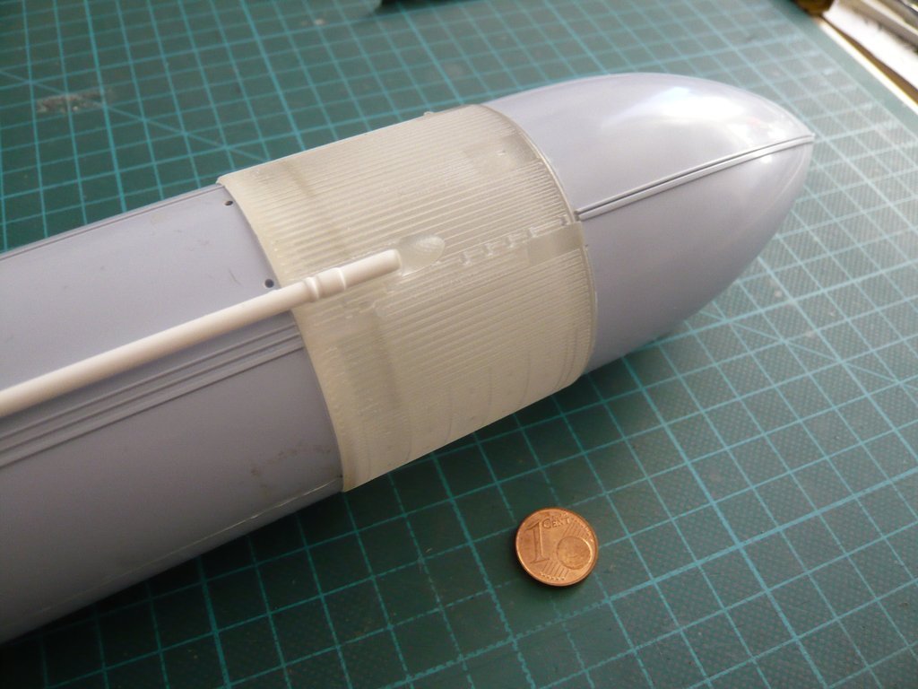
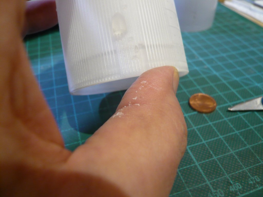
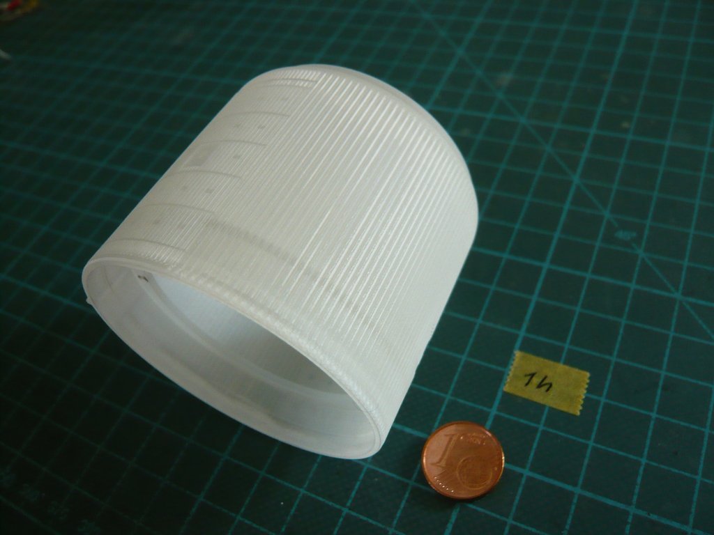
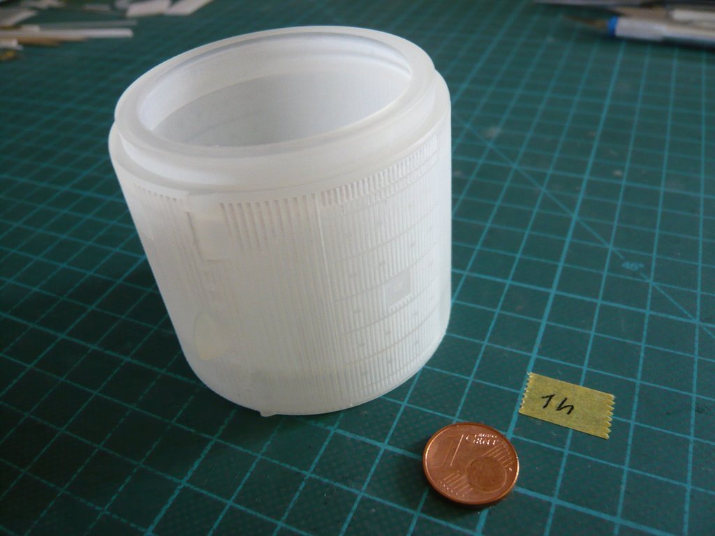
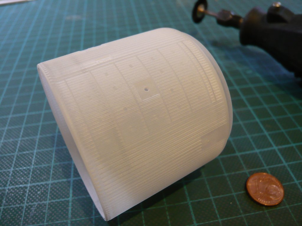
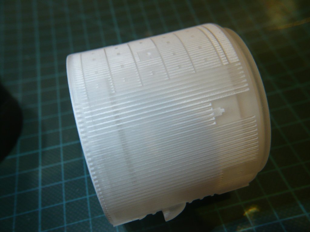
Anyway, I’ve let clean the FUD rings twice 600 seconds, so for a total of 20 minutes with some drops of rinse aid, after which they looked whiter than before, which has already been described by other guys.

This can be seen by this comparison between the cleaned [FUD rings (left)/color and the uncleaned FXD rings (right), although it is not serious.

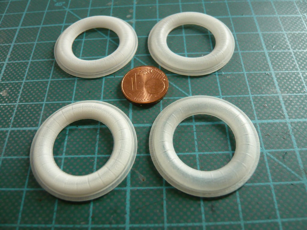
And here are the two FXD rings (right) after 20 minutes of cleaning.

BTW, the liquid looked so cloudy after cleaning of total of 40 minutes cleaning time of the four ASTC Rings, which shows in comparison to the picture before the cleaning already a quite enriched state with detached wax. https://forum.raumfahrer.net/Smileys/yabb/huh.gif

As far as to my first ultrasonic cleaning attempts.

P.S.: Shapeways is still remaining silent, whatever that may mean.

4 Likes

Hello everybody,

only a short but good news, Shapeways has meanwhile accepted my complaint and granted me a refund.

Now, Michael Key can do some minor changes.

2 Likes

Great catch up and always nice to see progress or ways which issues get fixed …. btw, that chain looks amazing !!

Thanks John, https://www.britmodeller.com/forums/public/style_emoticons/default/bow.gif but the chain unfortunately is not mine. It’s from an advertising video by the company BANDELIN for ultrasonic cleaning.

1 Like

ahhh got you …. but it does look good if it works that well.

1 Like

Hello friends,

only some thoughts to minor changes. cool1

In consultation with Michael Key we will now omit the inner tube completely, as there would probably be problems with the removal of the support material, which could possibly resist the ultrasonic cleaning. Then one would have to drill out the tube, which seems to me but too risky. https://forum.raumfahrer.net/Smileys/yabb/rolleyes.gif

BTW, I did not want to believe it at first, but there was one thing which I have noticed in retrospect on the 3D print, what I have overlooked at the 3D renderings.

The front part of the LO2 PAL Ramp of the 3D model has almost the same width as the back part of the LH2 PAL Ramp, but this is a mistake and does not match the original optics. https://www.britmodeller.com/forums/uploads/emoticons/default_fraidnot.gif

The LO2 PAL Ramp is too narrow and therefore needs to be widened, as one can see in these images. And actually, both ramps end up on the stringer top and do not run to the valley as before. https://forum.raumfahrer.net/Smileys/yabb/rolleyes.gif


Source: shapeways.com (The Aerospace Place)


Source: NASA

But that can certainly be corrected so that the optics are right again.

3 Likes

Hello everybody,

actually I had thought that Michael Key had to make only small changes. But it came different again …

First, he has omitted the inner tube as well as modified the LO2 PAL Ramp (right) as desired, which looks much better. cool1


Source: shapeways.com (The Aerospace Place)

However, I noticed that he did not modify the LH2 PAL Ramp in the same way, which I took for granted and therefore have not said it again.


Source: shapeways.com (The Aerospace Place)

But about his change of the diameters of the IT to reduce the slightly too large overhang at the rear end (Ør 60,0 mm) I was then quite shocked, because he accordingly must have misunderstood my image with the diameters of the Airfix Intertank and the values measured at the 3D print (red on white ground). https://images.raumfahrer.net/up037692.gif

But in hindsight, I must confess that the picture has become rather confusing and misleading. https://forum.raumfahrer.net/Smileys/yabb/rolleyes.gif

Because he had now set the front diameter (Øf) of the IT to 57,0 mm and the rear diameter (Ør) to 58,0 mm, so that it is consistent with the front and the rear part of the ET. As a result, there should be no overhang of the IT, neither front nor back, but which in reality is not the case because of the Stringer/Ribs and has never been up for discussion, on the contrary. https://www.britmodeller.com/forums/uploads/emoticons/default_fraidnot.gif

Maybe that the rejuvenation of IT by 1 mm seemed to have got mixed up him, which was obviously difficult to implement in modeling.

The bad thing was that he had already uploaded this disimproved Intertank to Shapeways. https://forum.raumfahrer.net/Smileys/yabb/rolleyes.gif

After that I have showed him the different diameters of the three ET parts again clearly in the following pictures and explained the differences.

D2 and D3 are the small overhangs of the Airfix IT that need to stay that way.

On this image one can see the connection diameter D2.1, which has to fit into the ET front part (D1.1), and the diameter D4.1 of the heel of the ET rear part, which has to fit into the Intertank,

whose inner diameter D3.1 can be seen here.

Hopefully this should have made it clear that we need the overhangs, so I asked him for the necessary changes in the hope that he could clench his teeth and be able to do it. cool1

Apparently Michael Key has that now understood and has adjusted the LH2 PAL Ramp as well as the rear IT diameter D3 to 59,0 mm and the front diameter 58,0 mm and then uploaded his model again.

And so the Intertank now looks at the Shapeways-Website, whereby he has become even cheaper by the removal of the inner tube with € 69,44.


Source: shapeways.com (The Aerospace Place)

I just ordered it again and hope that all good things come in threes.

3 Likes

Hello everybody,

but meanwhile back to another subproject, the [Ice/Frost Ramps() on the LH2 External Tank, and maybe Michael Key can also help me again. cool1

In fact, there are 17 Ramps, with the rear three ramps looking slightly different than the front 14.


Source: NASA

And that’s how most of the Ramps for the GO2/GH2 Press. Lines look like.


Source: NASA

My ARC friend Bill (niParts) has already modeled a Set of these Ice Ramps in 1:72, but in 1:144 they are much smaller and could possibly be problematic for 3D printing. https://forum.raumfahrer.net/Smileys/yabb/rolleyes.gif


Source: shapeways.com (niParts)

In reality, the ramps are 2’ x 2’ x 1’, and accordingly 4 mm x 4 mm x 2 mm for the ET (1:144).

The diameter of the GO2/GH2 Press. Lines is 2’’ = Ø 0,35 mm (1:144) and is used as the reference gauge.

The openings in the ramps are slightly larger, approx. Ø 0,5 mm, as one can see on this image.

Possible that the small wall thicknesses for Shapeways pose a problem, https://forum.raumfahrer.net/Smileys/yabb/huh.gif but which I do not hope.

2 Likes

Hello everybody,

when I started to deal with the Intertank and the SRB’s Aft Skirt Thermal Curtains (AFTC), I got to know a friend in the Britmodeller Forum (PZRGREN), who also had used this Newware Enhancement Kit and asked him for detail photos, especially from the ET and the Ice/Frost Ramps, etc. … cool1

Thereupon he has sent me some interesting photos of his ET with the SRBs, on which one can see some of the great kit parts installed.


Source: britmodeller.com/forums (PZRGREN)


Source: britmodeller.com/forums (PZRGREN)


Source: britmodeller.com/forums (PZRGREN)

Since the representation of the ramps in the construction manual of the Newware Kit is very detailed and clear, and the resin parts also make a very good impression,


Source: arcforums.com (egt95)

I asked my friend to send me some close-ups of the Ramps. Then he offered surprisingly, in addition to the photos to send me also his spare parts and the instructions, what I have thankfully accepted, a really nice gesture from him.

And since I have seen in the instructions that in the associated PE board among other things even the tiny hinges for the Payload Bay Doors of the Challenger are included, which he does not need because he has built the Atlantis I’ve also asked him about it.


Source: arcforums.com (egt95)

And he kept his word and in the meantime has sent me the promised things.

As one can see on this image, there are a few spare parts of almost all the Ramp types, on which I will go into detail, one of which lies on the cent coin. And I have to admit, the parts look really nice, whereby one should not be shocked by the chunky resin blocks. One just has to separate it carefully enough so that there is still something left over from the midgets.

The openings for the two Press. Lines are actually hollow, and here I have inserted a Nickel silver wire (Ø 0,4 mm), which I will use.

The openings are dimensioned slightly larger than real necessary, so that even a Styrene rod (Ø 0,5 mm) fits through, and there is enough space for the Evergreen Strip[/color] (0,75 mm x 1 mm) for the Cable Tray, as suggested in the kit, which is slightly oversized, wherefore I will use a smaller strip (0,5 mm x 0,75 mm) that is placed here. cool1

The spare parts are indeed not sufficient, but are well suited as a template for the 3D modeling, since of this R23 Type alone 14 pieces are needed, as one can see from this kit drawing.


Source: http://mek.kosmo.cz/newware/nw131.htm

With that I want to let it go for now.

4 Likes

What’s with these annoying ads in my post? Can’t the Admins stop them? https://images.raumfahrer.net/up043952.gif

If this doesn’t stop, I’ll stop posting.

1 Like

Thanks Admins, where is a will there is a way too.

Hello everybody,

Shapeways’ shipping did not take so long, if you have been wondering about the send pause. cool1

The reasons for that I still want to explain before the holidays, but the devil is often in the detail, or better said in this case in the [color=blue]Shapeways’ tolerances[/color], which I have not yet known so far. https://forum.raumfahrer.net/Smileys/yabb/rolleyes.gif

And if one or the other in the mean time has clicked on the link of the SW website in my Reply # 1453, then he will has been surprised. Oops!!!

Outwardly, the second Intertank looks really great,

but already the test fitting of the ET front part was not possible because the connection diameter D2.1 was still slightly larger than that of the first IT, namely instead of 53,5 mm it was now even 54,1 mm. You could have knocked me down with a feather!!! https://images.raumfahrer.net/up037692.gif

Instead of getting a little smaller by Michael Key’s adjustment for a better matching the Airfix IT-values, the dimensions became in spite of taking shrinkage (0,8%) into account amazingly even a bit larger, which is still mystery to me.

This is shown by the comparison of the dimensions of the two ITs with the Airfix-IT,

whereby I’ve tried to measure as accurately as possible. cool1

While the larger length is less a problem for the fit of the parts, https://forum.raumfahrer.net/Smileys/yabb/rolleyes.gif

the resulting diameters all the more so as the overall IT was printed too large, which can also be seen at the back overhang of the IT, which is just too big for me. https://forum.raumfahrer.net/Smileys/yabb/huh.gif

Of course, Michael Key was also very surprised, because according to the SW website, the visible length of the IT (without front connecting ring) should be around 48,9 mm (48,5 mm x 1,008 shrinkage), as it was indicated in his CAD file.

He then removed his shop offer https://forum.raumfahrer.net/Smileys/yabb/rolleyes.gif and contacted Shapeways for anew refund, which I’ve received in the meantime.

While the tolerance for FUD on the SW website is indicated with

Accuracy ± 0,1 - 0,2 mm for every 100 mm,

we have now been told that the actual tolerance of the material is up to 0,4 mm, so one can not guarantee that the IT is perfectly sized, which is inconsistent and in my opinion difficult to accept it.

Normally it is absolutely a No go!!! It is unacceptable for the customers that SW simply declares new tolerances that are twice as large if the specified limits are not met.

And therefore I will inform SW that I’m expecting their guaranteed FUD accuracy for the proud price of this print. https://forum.raumfahrer.net/Smileys/yabb/rolleyes.gif

However, in a sketch by Michael Key with all dimensions of his CAD model without and with shrinkage (0,8%), I discovered a small flaw that may have contributed to the enlarged diameters, which he has now corrected. https://forum.raumfahrer.net/Smileys/yabb/huh.gif

With these last changes, he has uploaded the model again.

Now he will also upload a WSF version, which does not have to consider shrinkage and which will surely become a bit cheaper.

4 Likes

Continuing with the outstanding build process… detail remains constantly superb down to the smallest detail.

Thanks John, https://www.britmodeller.com/forums/public/style_emoticons/default/bow.gif

I can’t get down from this detail level anymore.

2 Likes

Hello everybody,

today with a short update from the Shapeways Team. cool1

I just could not stand for this contradiction regarding the FUD tolerances and had asked the friendly Shapeways lady, who initially wanted to give me only a lapidary, meaningless answer , to explain this dilemma to me.

Thereupon was it confirmed by a production colleague that the maximum accuracy that SW can achieve at FUD is actually 0,4 mm, and that the SW guidelines should be adapted, to what one would now work on. https://forum.raumfahrer.net/Smileys/yabb/rolleyes.gif

Well at least something for which my effort has been worthwhile, although still to this day one finds the unchanged previous precision specification of ± 0,1 - 0,2 mm for every 100 mm

Meanwhile, the third IT is on its way to me, and I’m curious what it will look like.

In the meantime, I’ve looked around a bit on the SW pages and now I can better imagine the matter with the Support wax, whereto I have found this nice image at the end of the FUD website with the following explanation.


Source: shapeways.com

And remnants of this stuff one has still to remove off afterwards from the printed parts, although the cleaning at SW actually belongs to the standard procedure, but what is apparently not quite enough.

After printing, the models are placed in a freezer to help detaching the parts, and then into an oven, where the wax base melts. Then they are placed first in an ultrasonic oil bath and subsequently in an ultrasonic water bath to remove residual wax and oil residues, and finally, after thorough water rinsing, they are dried and finally tested.

Here is an image of the second IT, which looked a bit cleaner than the first one.

The traces of grease on the paper show, that remnants of the wax/oil remains for the customer unfortunately, https://forum.raumfahrer.net/Smileys/yabb/rolleyes.gif

here during the sunbath of the two ITs for the allegedly necessary complete curing of uncured microscopic resin areas under UV light,which was proposed by a shapeways designer, who was presenting some useful tips (FAQs) on how to use Shapeways prints.

3 Likes

Hey everyone,

meanwhile, I have received the third IT, which makes a much better figure than the first two, cool1

and fits also better between the two ET parts, as one can see here.

And here the LOX Feedline from the Revell Stack was laid down experimentally. cool1

As my remeasurement has shown, but no shrinkage seems to have occurred, so one would probably get along without the 0,8% addition.

Then I started with the tests for ultrasonic cleaning of the IT, for what I used the 2nd IT. To grope me step by step to the required cleaning time, I have each set the longest interval (600 sec.), which was repeated several times in succession. https://forum.raumfahrer.net/Smileys/yabb/huh.gif

First, I put the IT on the rear end and cleaned it in from this side a total of 30 minutes, with about 80% were immersed.

After this first cycle, the water looked rather cloudy, https://forum.raumfahrer.net/Smileys/yabb/rolleyes.gif

and was therefore renewed for the cleaning of the other side, which then also took 30 min..

After that the IT looked like this, whereby one could see at a closer look but still wax residues in the grooves, which is why half an hour apparently was not enough.

Therefore, I helped along with the electric toothbrush under running water, because the fine grooves between the stringers are obviously the purest wax catchers, which I had already feared.

But since even after this action still small wax remains were to be seen, then I grabbed the cutter and went on carefully further cleaning out the interspaces, which is also quite effective, as can be seen at the stripped off residues on my thumb,

as well as at the cutter tip.

This stuff seems to sit so firmly in the grooves, so one will need much longer cleaning times in the ultrasonic bath, as initially suspected. https://images.raumfahrer.net/up037692.gif

Therefore, I’ve added another pass of 30 min., which now gives a total cleaning time of 1 h, after which the water is always still cloudy.

But as one can see at these photos, there are still areas with more or less wax residue.

That immediately reminded me again of the 3-4 h cleaning time during cleaning a FUD chainhttps://images.raumfahrer.net/up037692.gif

So I will either extend the cleaning time still significantly, or sometimes have to try Aceton, or are there any ideas of the Shapeways experts here in the forum?

2 Likes

Hello everybody,

okay, it looks like there are no Shapeways experts in the forum.

Following a hint in our German Raumcon Forum, I looked in my Dremel accessories]() and also found a Nylon Rotor Brush and a Nylon Brush, which I have immediately tested at medium speed. cool1

In addition to the disadvantage of the many fine grooves, the Intertank has the advantage that it has no protruding small details that can easily break off when brushing, and also it is quite robust.

That’s why I was able to ride across the grooves relatively easily and smoothly with the rotor brush, whereby it was already visible to the naked eye how the white wax residues gradually disappeared and the grooves slowly became clean, which pleasantly surprised me.

While cleaning in the area of the Stringer Panel is relatively easy due to the continuous grooves,

one has to do one’s best in the subdivided areas of the Thrust Panel. https://forum.raumfahrer.net/Smileys/yabb/rolleyes.gif

Under the big magnifying glass, one can see more clearly the differences between areas with wax residue and already cleaned areas.

And furthermore one can still see that in the two outer areas of the Thrust Panel on the right edge with the little “pockets” still sits a lot of wax, because they are worse reachable with the Rotor brush, which is why I there will try the Nylon brush that will probably get in better there.

To be able to see such differences in detail even better, I always did apply the following trick.

To do this, I paste the photo into a Word document, then I increase the magnification, as shown here e.g. up to 300%, and take a screenshot, which I then upload.

This closeness can no longer be captured by the autofocus of my digicam. https://forum.raumfahrer.net/Smileys/yabb/rolleyes.gif

This is the maximum possible closeness, if the image is still to become halfway sharp. https://forum.raumfahrer.net/Smileys/yabb/huh.gif

And here I’ve tested the Nylon brush, and I have to say that does not look too bad.

The cleaned area stands out clearly from the rest of the area, whereby one must consider that this IT was already 1 h in the ultrasonic bath.

BTW, an interesting suggestion came from another modeler, after what I should put the IT completely in warm water with a few drops of detergent overnight, about 8 to 10 h. This time should be sufficient for the detergent to soften the bond between the wax and the FUD. Thereafter, the IT should be put into the ultrasonic cleaner to finally detach the residual wax.

This “Long pre-soak” Method is known to be used in industry for quite a number of cleaning processes.

This Intertank with its many fine grooves seems to be a prime example of a “wax catcher” 
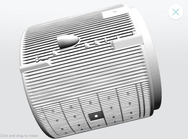
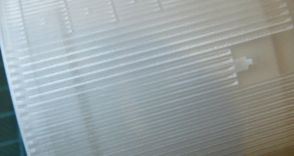
and therefore obviously needs a combined special cleaning treatment.

But I will not let up until I have found a way out, rely on it. cool1

Therefore I’m going to try the Pre-soak method (maybe a day or two) with my 1st IT, whereby it actually seems logical that soaked “dirt” can be removed better, as in grandmother’s time …

And maybe the brushing out of the grooves with the Dremel brush can also be done under water.