Space Shuttle Launch Complex 39A with Challenger STS-6 (1:144)

You have the advantage of already knowing more about my project, so I don’t want to give anything away.

The flour technique is certainly time-consuming, but at the same time a promising way to replicate the ET SOFI structure. Therefore let’s wait and see Brother.

1 Like

Hello everybody,

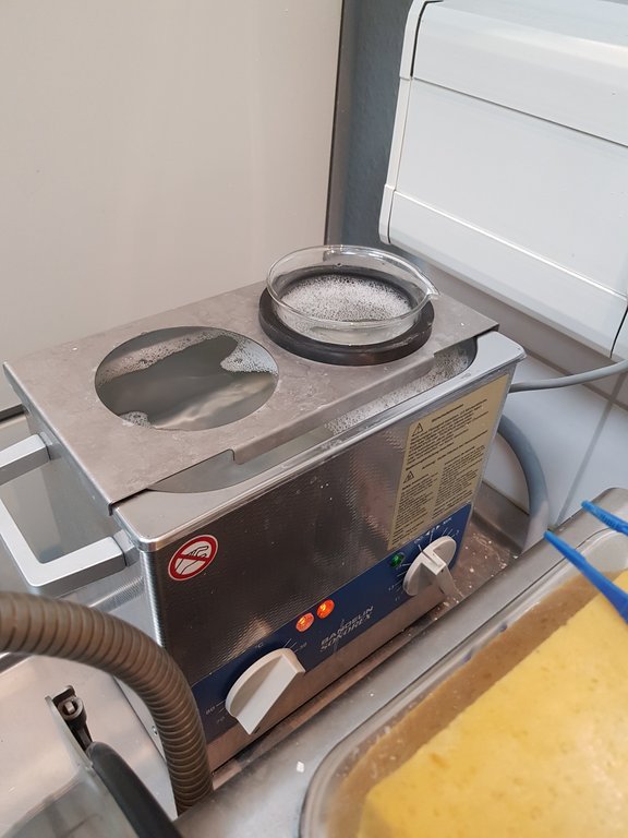
after the tough struggle for the rings of the ET SOFI now back to the grooves of the last FUD-IT, whose ultrasonic cleaning in my Dental Lab was still on the agenda.

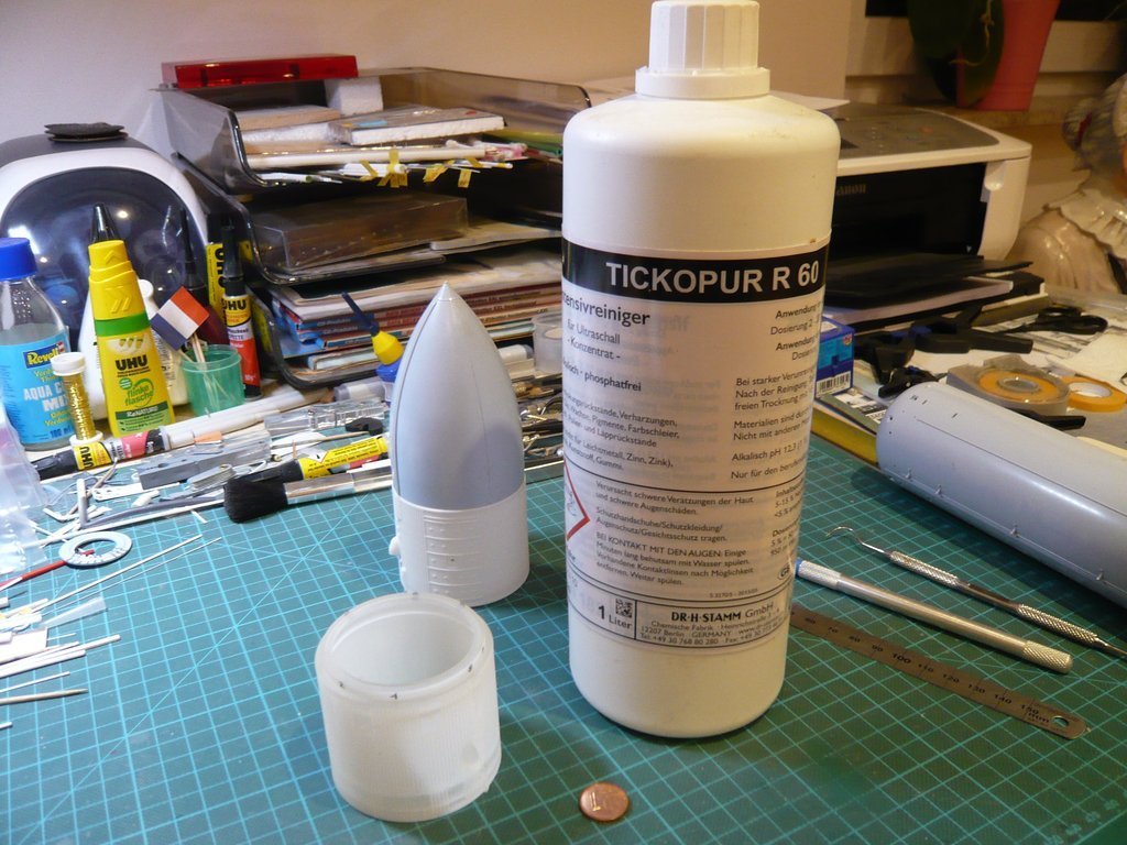
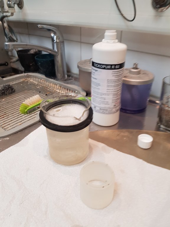
For that I had procured the recommended intensive cleaner TICKOPUR R 60,

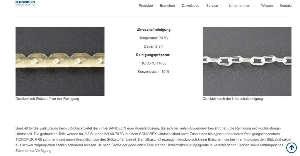
which we wanted to use based on the conditions recommended by BANDELIN.


Soucre: bandelin.com

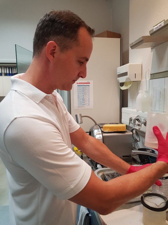
Since this cleaner i.a. Sodium hydroxide (5-15%), also called caustic soda, caution was bidden, which is why protective gloves were required. https://forum.raumfahrer.net/Smileys/yabb/huh.gif

After the nice colleagues of the ChiliDent Lab were back on board after their short break, it was finally time and the Final Countdown was imminent.

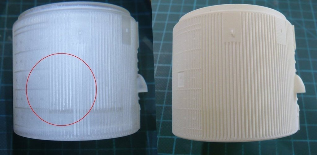
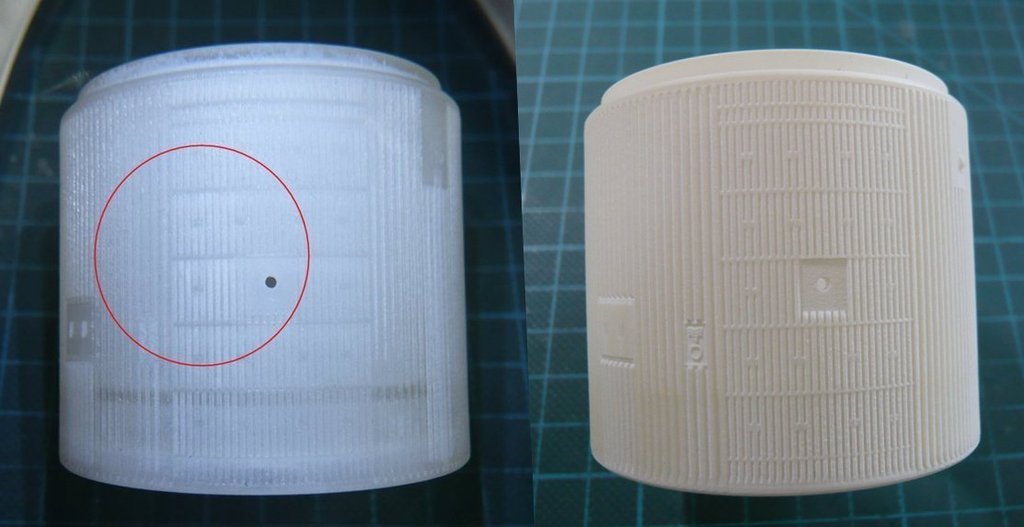
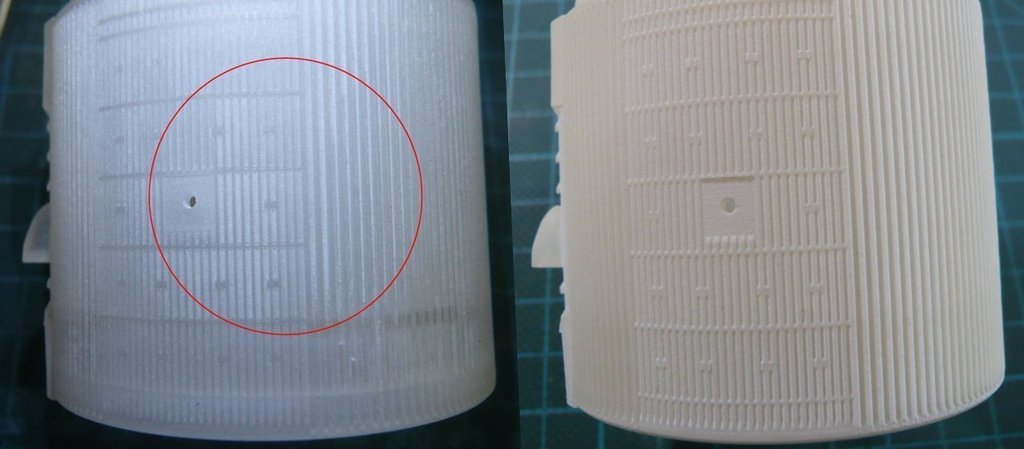
In the beginning of May I had presented the photos of the critical areas with the strongest wax nests as you can see again below. https://forum.raumfahrer.net/Smileys/yabb/rolleyes.gif

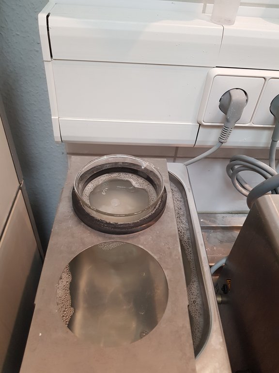
In order to shorten the cleaning time, we have increased the concentration of the TICKOPUR to approx. 20 %. Through the rubber ring, the height of the glass insert in the ultrasonic bath could be adjusted so that it hung about 3 cm above the bottom of the tub, which is as important for optimal cleaning as filling the tub with the same solution,

that the boss has personally mixed.

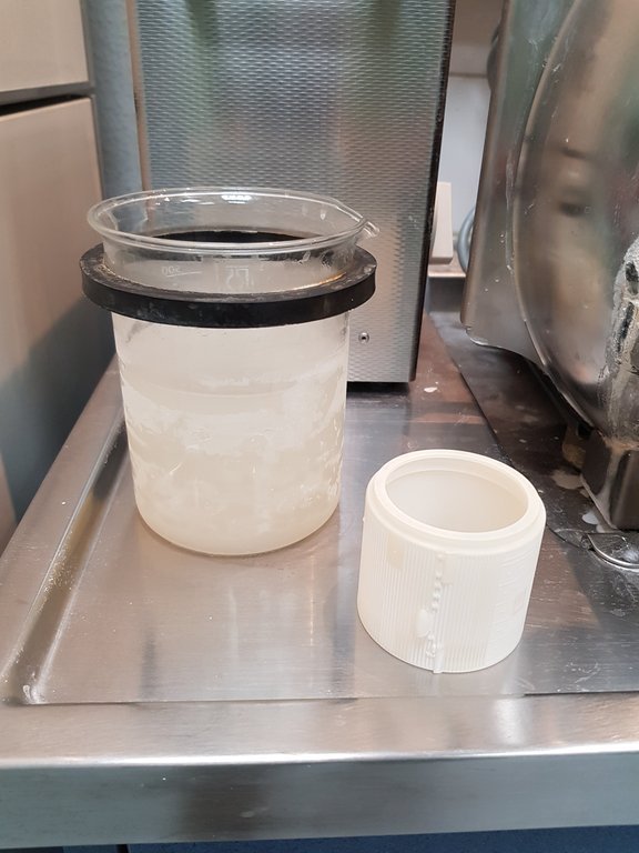
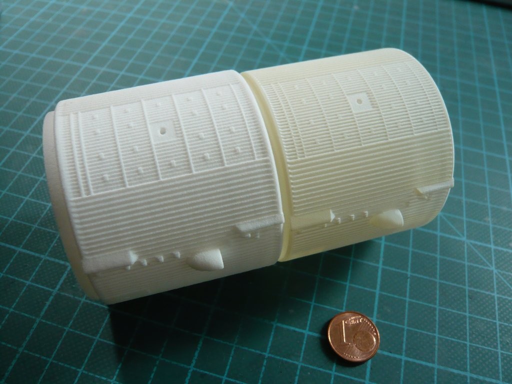
Due to the size of the glass insert, the Intertank could be inserted lengthwise, which is also advantageous for the cleaning effect.

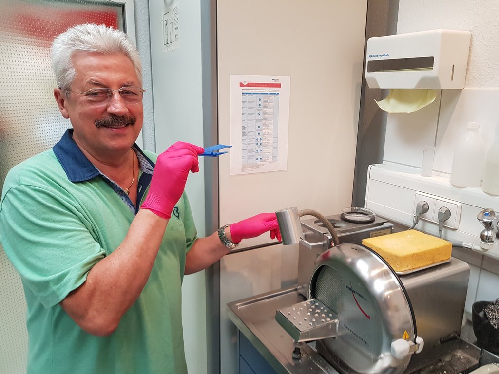
After setting the thermostat to 70°C, the appliance was switched on by the assistant,

and the bath began to bubble.

After every 30 minutes, the IT was turned a quarter turn further. Overall, the cleaning time was about three hours.

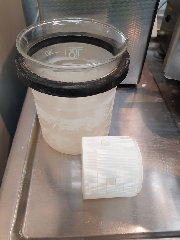
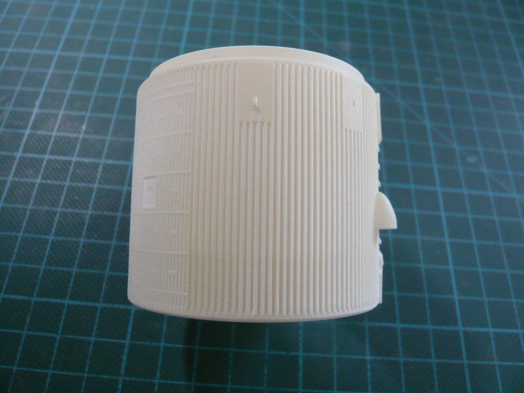
After that, the tank looked white and completely clean, which one could already see at first glance.

So finally the work was done, and with a tip into the kitty I thanked me once again and light-hearted said goodbye.

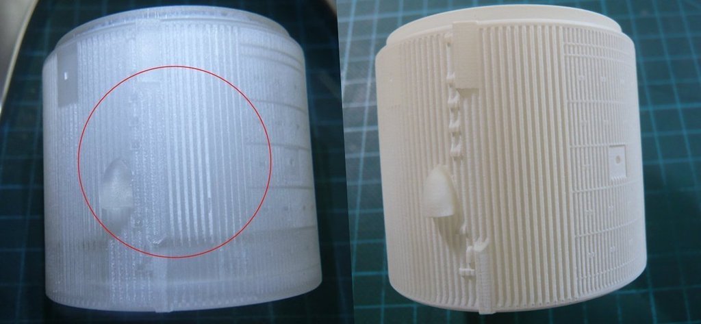
And as one can see in this photo, the cleaning was really perfect, because there are no wax residues left, https://images.raumfahrer.net/up037692.gif which is why no aftertreatment was required too.

This is especially also illustrated by comparing the photos before and afterwards.

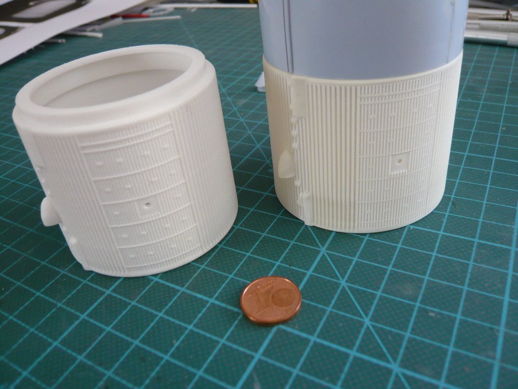
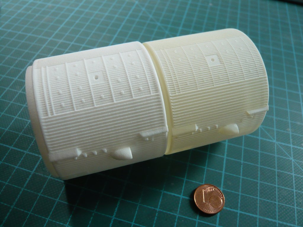
And here once again a few pictures of both ITs in comparison, where the FUD-IT looks even more filigree than the WSF-IT.

Nevertheless, I think that one can use both ITs, depending at whim and purse.

4 Likes

Hello everybody,

after finally defeating the wretched wax residue of my FUD-IT, https://www.britmodeller.com/forums/public/style_emoticons/default/fight.gif now I have to find a solution for the mysterious wavelike SOFI texture on the STS-6, ET-8 surface, what is a further exiting chapter.


Source: wikimedia.org

And then I’ll hope finally to come back to model building …

4 Likes

Hi everybody,

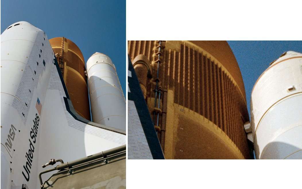
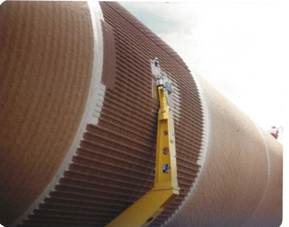
after my successful Ultrasonic cleaning of my FUD-IT I am currently on one of my obligatory voyages of discovery, still looking for the origin of this wavelike SOFI structure of the first generation of ETs, which one can see both on this photo of the ET-33 (STS-36) by George Gassaway,


Source: georgesrockets.com

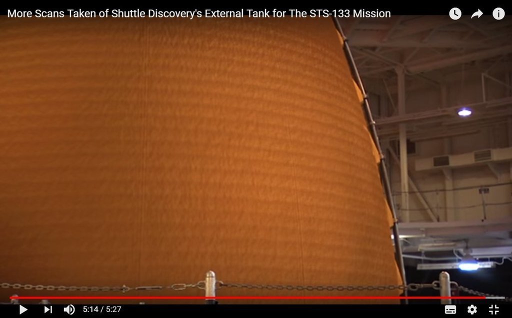
as well as on the LO2 tank (ET-137) in this video (5:14) before Discovery’s last mission ( STS-133).

In the meantime, I was following the traces concerning the ET production, which are known to lead directly to the Michoud Assembly Facility (MAF ), popularly NASA’s Rocket Factory.

Although I have not found any photos of the SOFI Cells, a friend from NSF forum (psloss) has posted an interesting hint to drawings from the assembly process of the ET production.

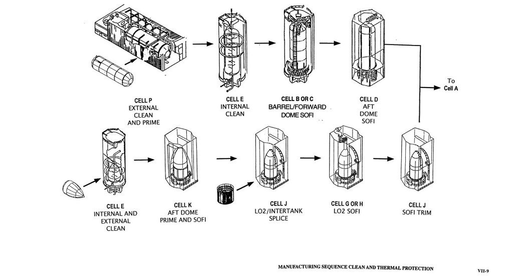
And they come from the PDF ‘Space Shuttle/External Tank System Definition Handbook SLWT, Volume II/2’, among others, also this picture here.

On it one can see the manufacturing and assembly cells, in which both the priming (Prime) and the SOFI Application of the LH2- and LO2 tanks, as well as the Intertanks took place.

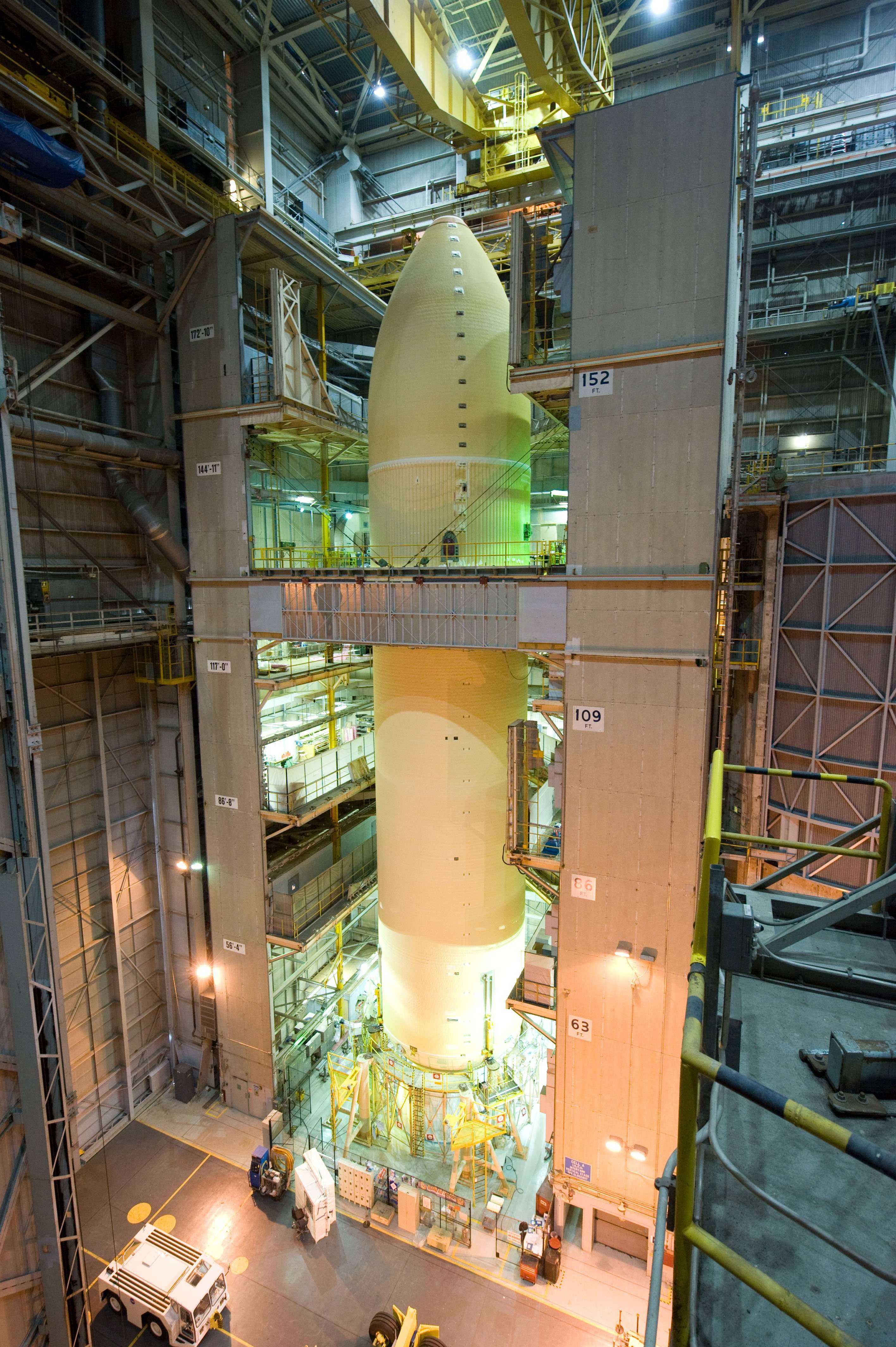
From there all ET parts went into the Cell A, where they were assembled vertically. And of this largest cell at that time, I also found an impressive picture by Jester (NSF), namely this one, which is linked to the Hi-Res. image, in which one can see a plate at the lower right corner with Cell A.


Source: forum.nasaspaceflight.com (Jester)

This success made me even more curious, and since I really wanted to find these special SOFI Cells of the MAF, I searched further. https://images.raumfahrer.net/up054540.gif

The difficulty lies in the fact that Google-searching for SOFI Application & MAF lead almost without exception to actual photos of their equipment there, but it must be noted that in the MAF after the end of the Shuttle Program (2012/13) all former equipment was dismantled or modified for the bigger tanks of the SLS Program, which does not help me much. https://forum.raumfahrer.net/Smileys/yabb/rolleyes.gif

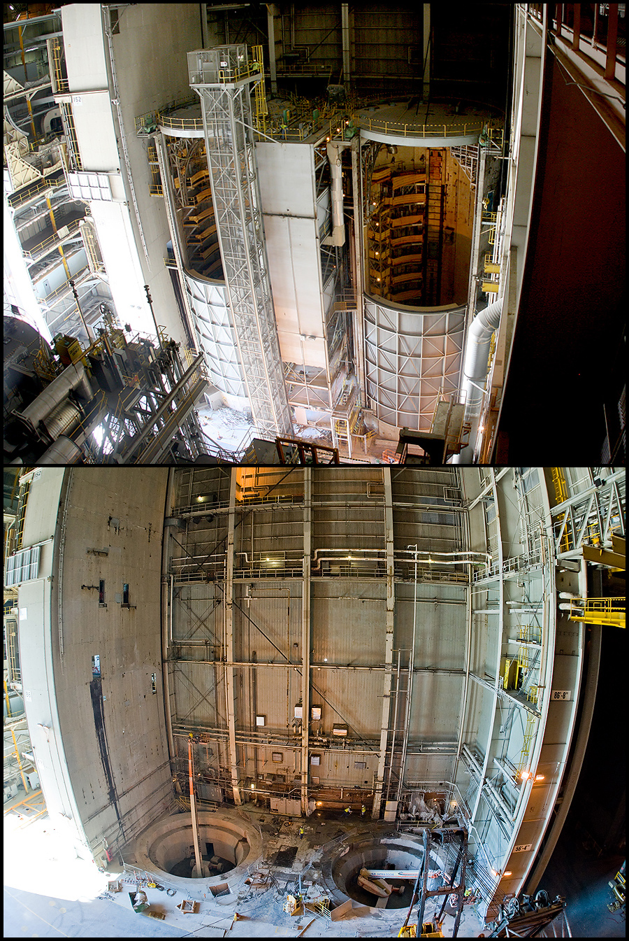
But in this context I finally found what I was looking for and came across this great photo combination, which shows Cells B & C in Building 110 both before (above) and after (below) dismantling, where the LH2 tanks received their SOFI-TPS at the time.


Source: blogs.nasa.gov

Since then, at this lace is standing the new Vertical Assembly Center (VAC) with the world’s largest Friction Stir Weld Machine for the production of the larger SLS tanks.

So far, so good, but that still left the answerless question of the explanation of the typical wavy ET SOFI structure.

As far as I know by now, 90% of the total ET-SOFI insulation was applied with an Automatic Gun Spray System](), and only 10% by hand, as can be seen here on the connecting flange between the Intertank and the LO2 tank.


Source: NASA

But how this automatic system worked in the SOFI cells and how and why this wave-like structure was created during coating still remains a mystery, but which I still want to solve it somehow, why the search goes on …

4 Likes

Hi everyone,

since I now know from two experts that I chase after no phantom, now a next step for the implementation of this wave-like ring structure on model ET.

As I’ve said already, there are these two discussed possibilities, either by a 3D printing, if Michael Key finally would have time and desire, or by Scratch-building. https://forum.raumfahrer.net/Smileys/yabb/undecided.gif

Since Michael Key for his 3D model but already should know about what shape and especially what dimensions should have this wavy line, I have now tried to draw a first scetch.

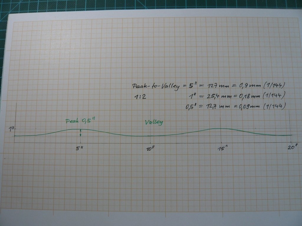
Starting from the Peak-to-Valley width of about 5’’ = 127 mm = 0,9 mm (1:144) specified by Vincent Morales, which roughly matches my previous estimates from photos, I have sketched the following profile (1:2), which should show this wavelike foam structure, how I could imagine it.

Considering that the average SOFI thickness on the ET is approx. 1’’ (25,4 mm), I have drawn a profile whose peak height I assumed with about 0,5’', which with approx. 0,1 mm in 1/144 would be very flat.

Now it would be important to find out how large this peak-height actually was at that time in the foam insulation.

Let’s see if/how the experts Craig Capdepon or Vincent Morales will comment on that, since they should actually remember it.

3 Likes

Be interesting to see the method of creating the wave pattern, it looks like another level of detailing to come !!

Then stay tuned John.

The smallest strips I am aware of are .010 x .020 inches. If that is small enough it it definitely a way to go.

Hello everybody,

unfortunately, there is no feedback from the two experts so far, whyever …

If I understood Vincent Morales right, that the Peak-to-Valley 5’’ is the spacing from the top of the wavy pattern to the deepest point of the valley, then the Peak-to-Peak is the spacing from one peak to the next one.

But somehow my 7th sense tells me that his 5’’ can’t be quite right, maybe it’s a bit to large, or I’m misinterpreting his term Peak-to-Valley so far. https://forum.raumfahrer.net/Smileys/yabb/rolleyes.gif

That’s why I took a different approach, because ultimately for scratch-building it is crucial, how many rings were on the ET, whereby the difficulty is only to determine this number as accurately as possible, wherefore I used these two Hi-Res photos.

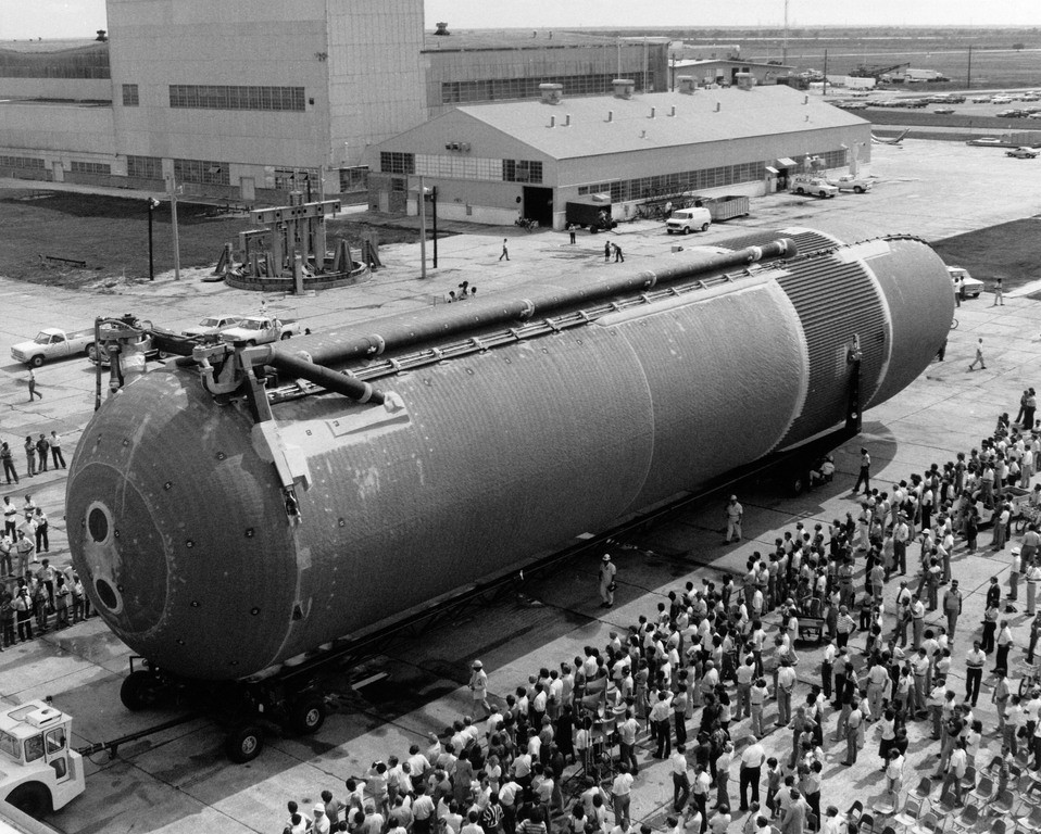
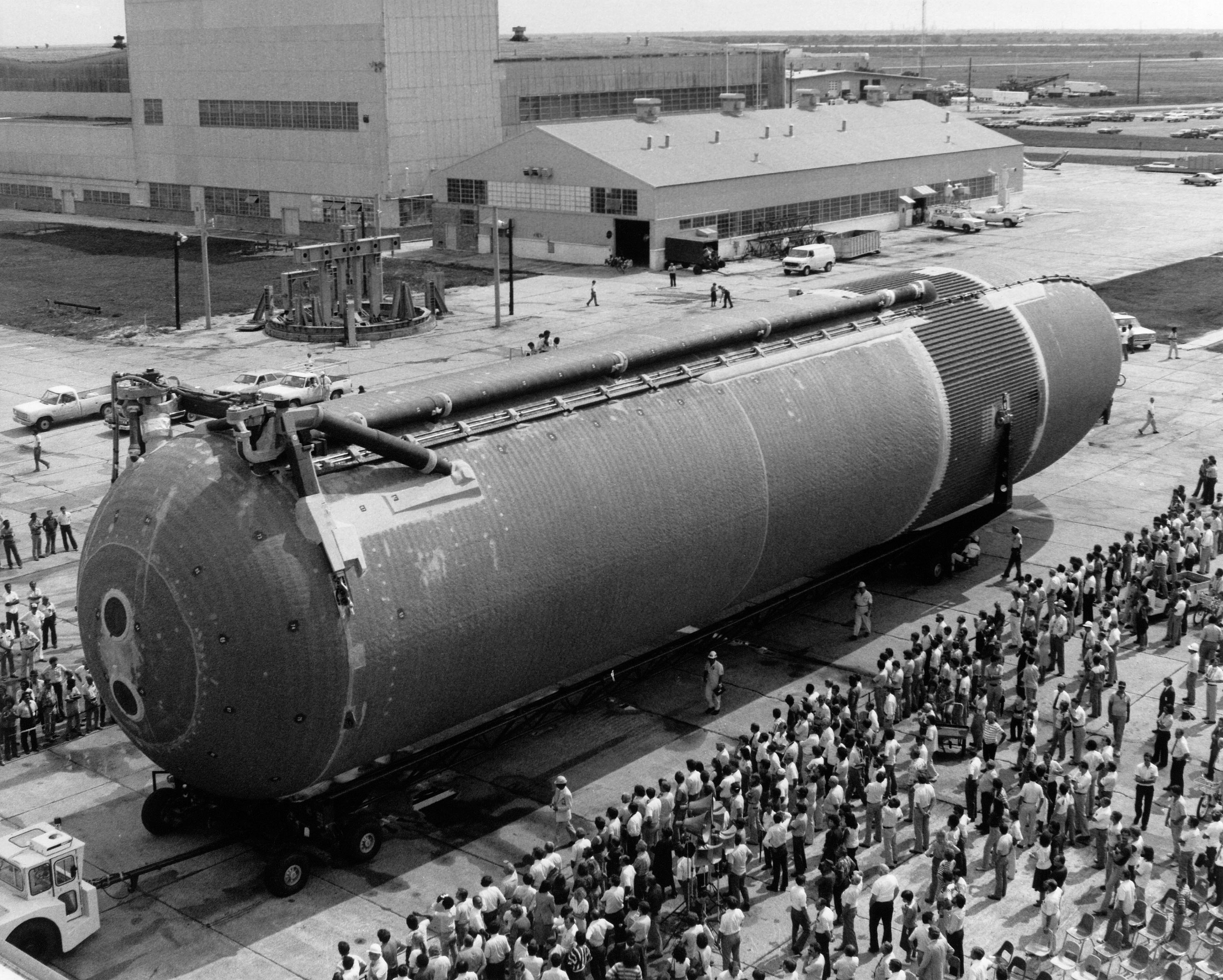
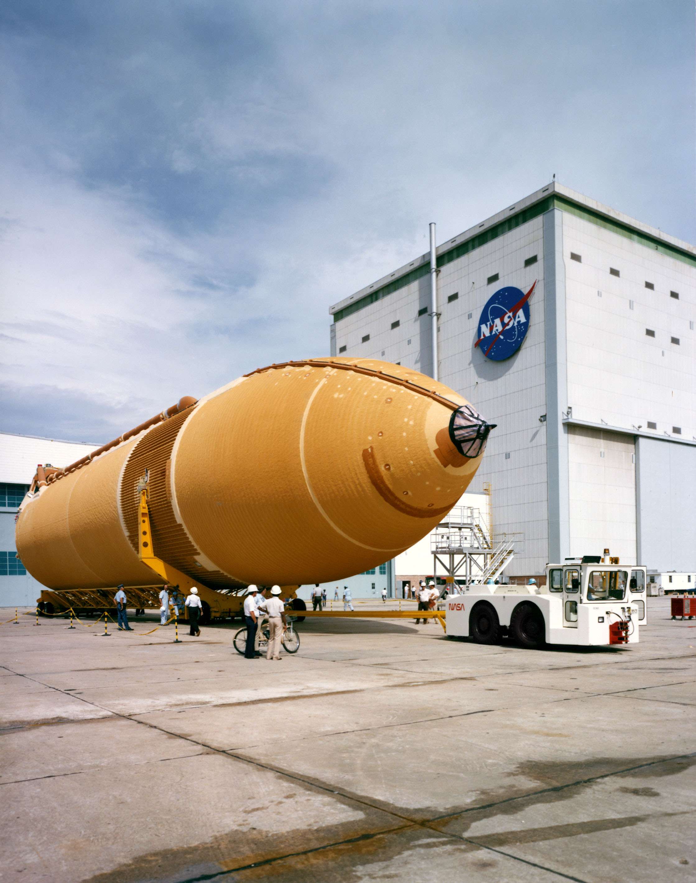
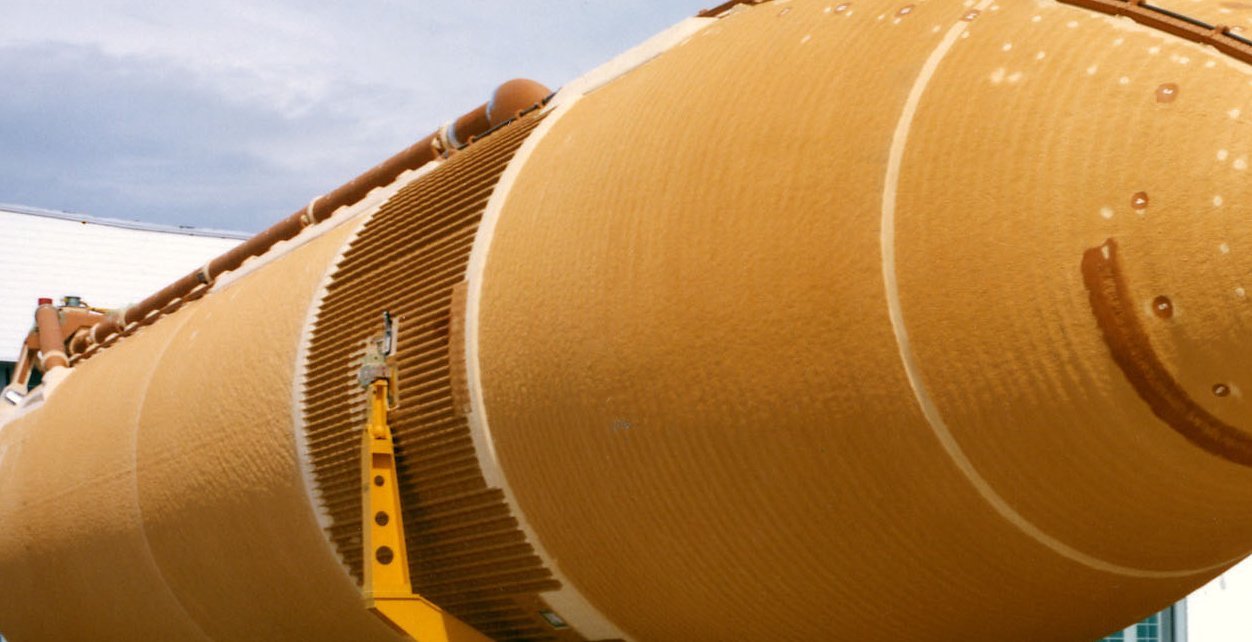
This old photo from the initial phase of the Shuttle program I wanted to evaluate anyway, because one can see this wavy ring structure on the LH2 tank quite clearly.

And meanwhile I also know that this photo shows the Rollout of the first LWT ET-8 for Challenger’s STS-6.


Source: forum.nasaspaceflight.com (Jester)

However, especially in the front area at the beginning of the LH2 tank, this photo is simply too fuzzy for an exact counting of the rings, whereby this is made even more difficult by the foreshortening.

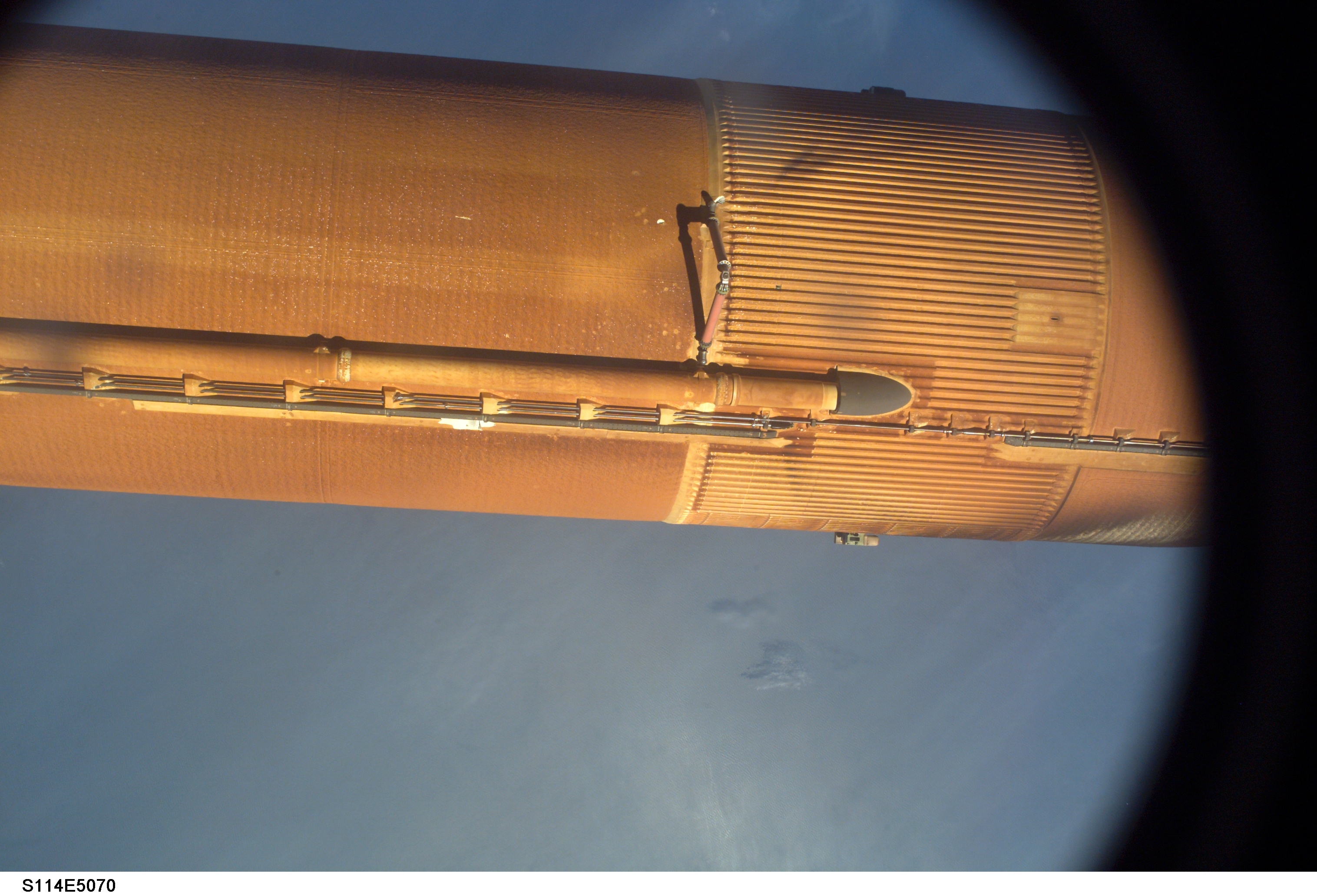
Therefore, I have used another photo for this, where one has almost a direct view of this area, namely this one of the discarded ET-121 (STS-114), in which one in Hi-Res-Zoom with a little imagination and a sharp eagle eye it is also possible to count out the rings in this front area.


Source: NASA

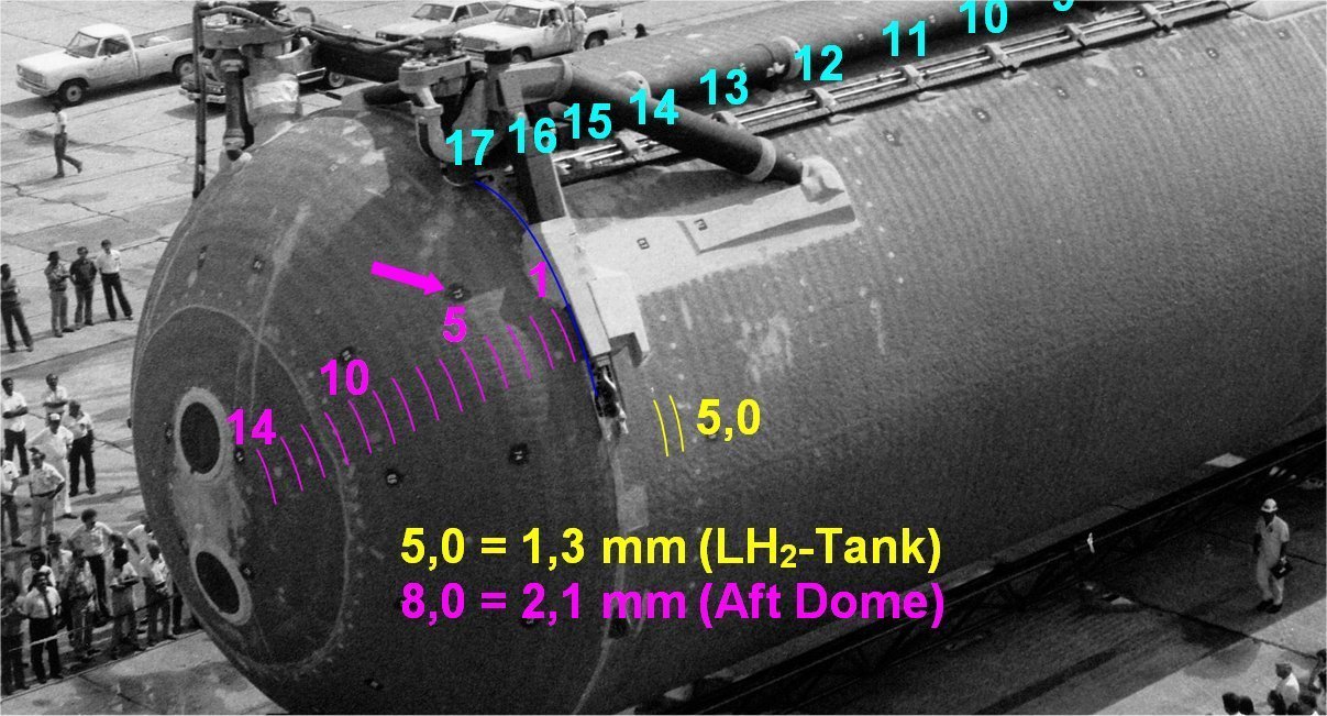
For better orientation on the tank, I have numbered the 17 Ice/Frost Ramps, in order to find the exact point for continuing the count up to the Aft Dome.

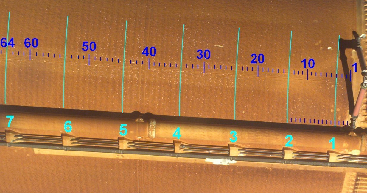
And then the counting went off, but first of all, I had to attach a few markings in order not to constantly have to re-count, when my eyes had gone on strike and lost the orientation. https://www.britmodeller.com/forums/public/style_emoticons/default/blink.gif


Source: NASA

And at this first count I came to 64 rings at the rear end of the Ice/Frost Ramp No. 7, although I have to admit that the counting between the first two ramps was extremely difficult. https://forum.raumfahrer.net/Smileys/yabb/rolleyes.gif

And then it went on in the other photo exactly at this point Ramp 7 (64), where the count was now increasingly easier.
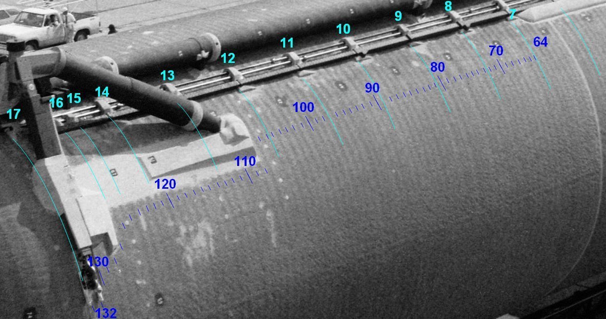

At the end of the tank I came to a total of 132 Rings.

What is following now from this for the width of the rings, which is actually the center distance of Valley-to-Valley?

Luckily, this calculation is now quite simple if I refer it directly to the length of the Airfix-LH2 tank (without Aft Dome), which is 170 mm, whereby I rounded the number of rings to 130 for the sake of simplicity:

170 mm : 130 = 1,3 mm per ring, which would be extrapolated 187 mm, which means 7,4’’ at the original ET, which is less than the Peak-to-Peak distance (10’') by Vincent Morales.

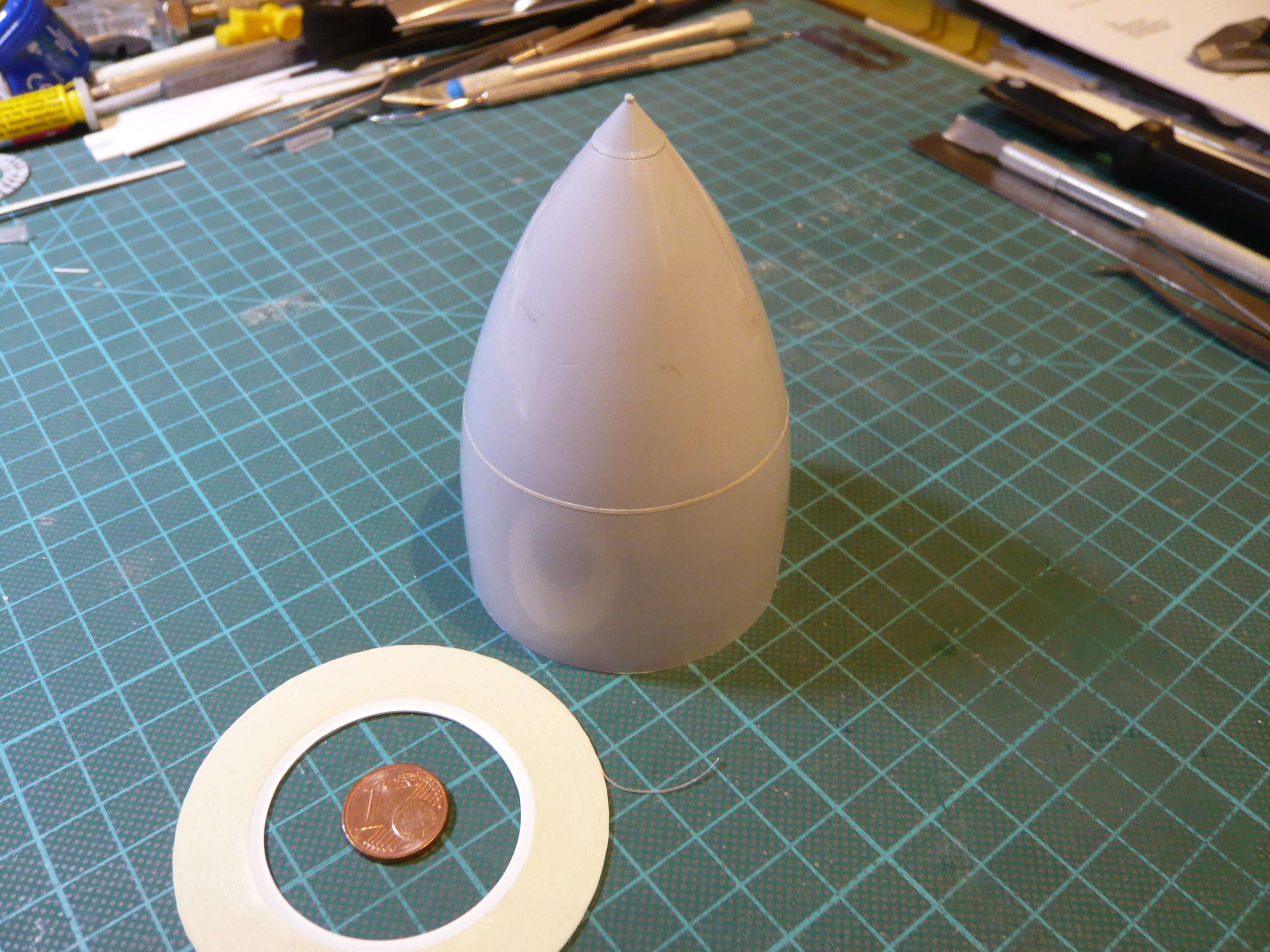
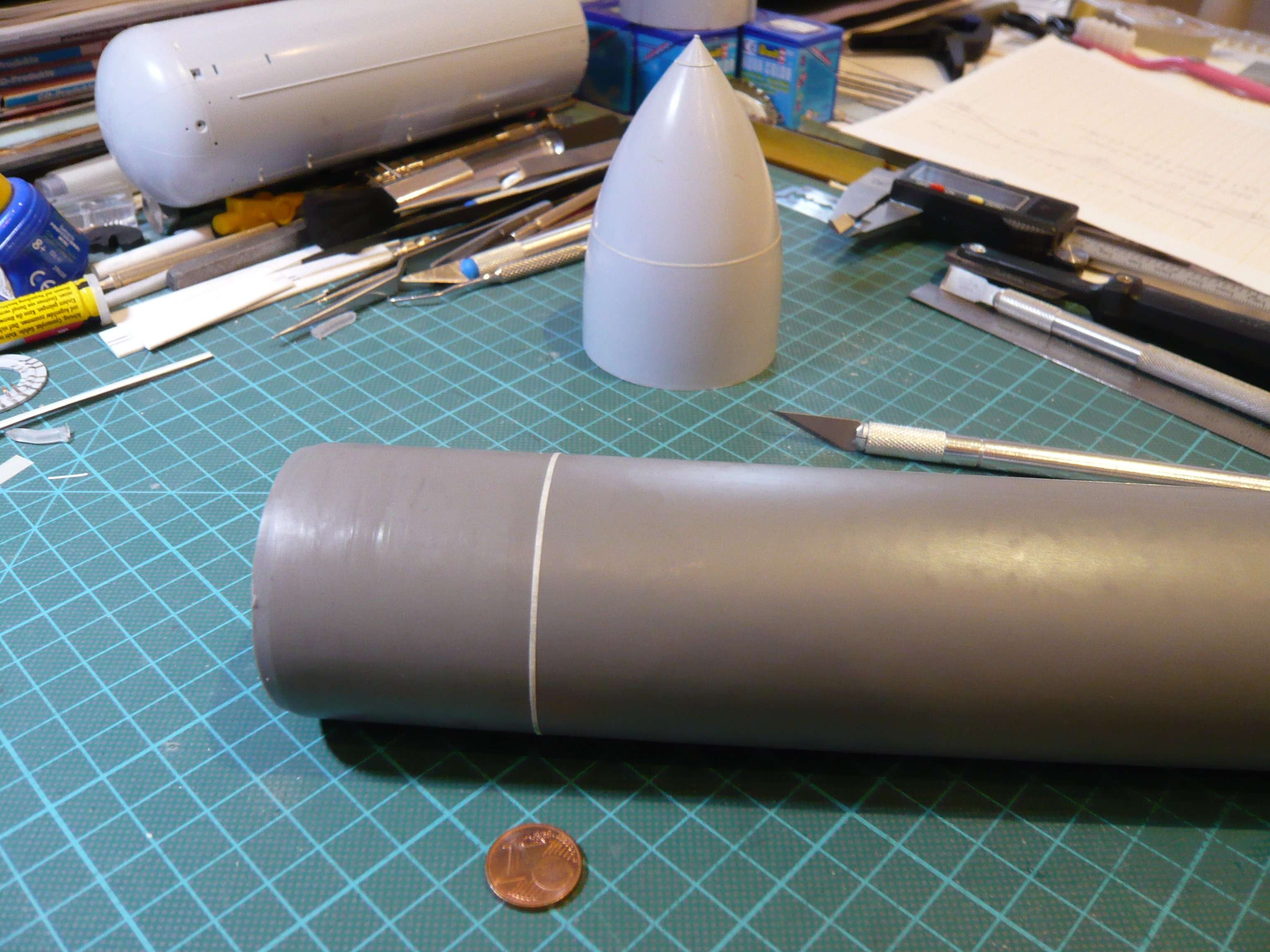
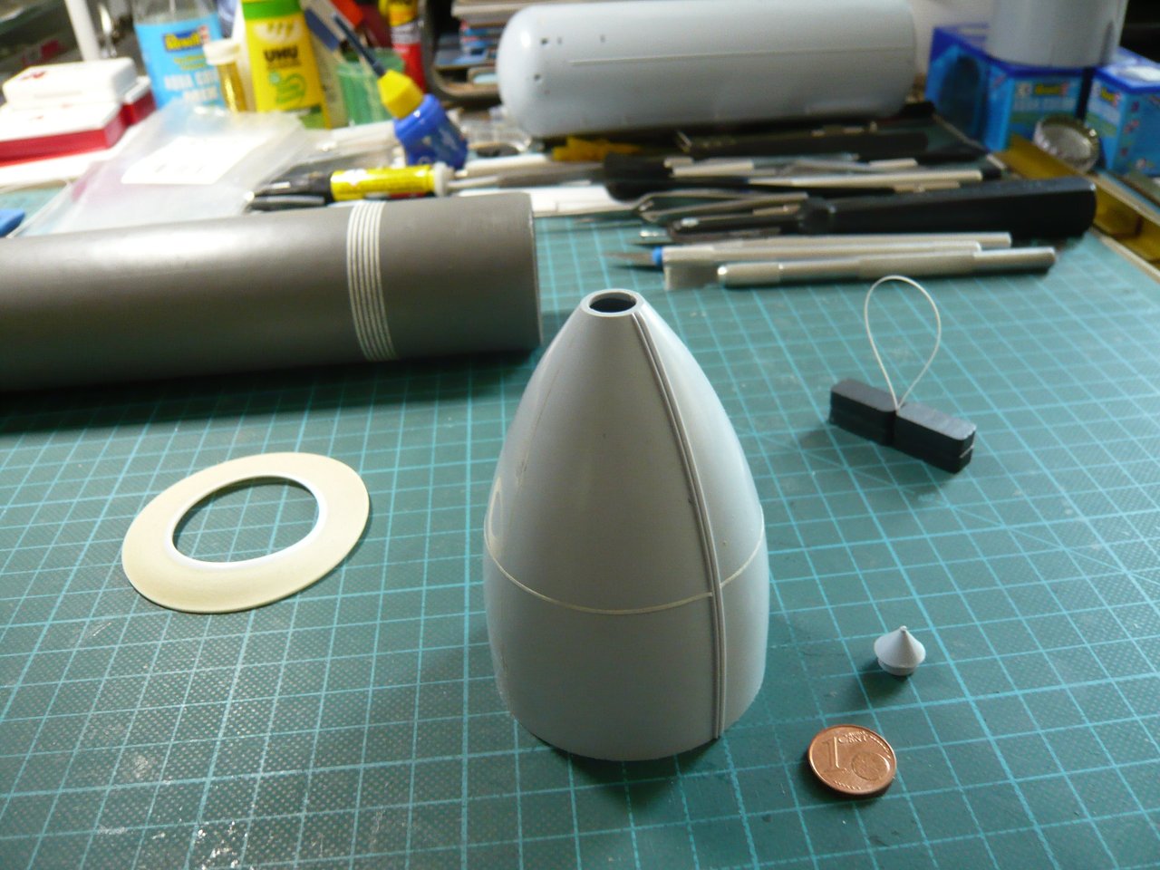
Now only the Peak height is still missing. But with the distance of 1,3 mm I can now at least determine the best width of the stripes and their distance for my test, possibly 0,75 mm instead of 1 mm with a tape (0,5 mm) as a spacer, what I’m going to try on this ET dummy (Ø 50 mm), which I bought at the hardware store.
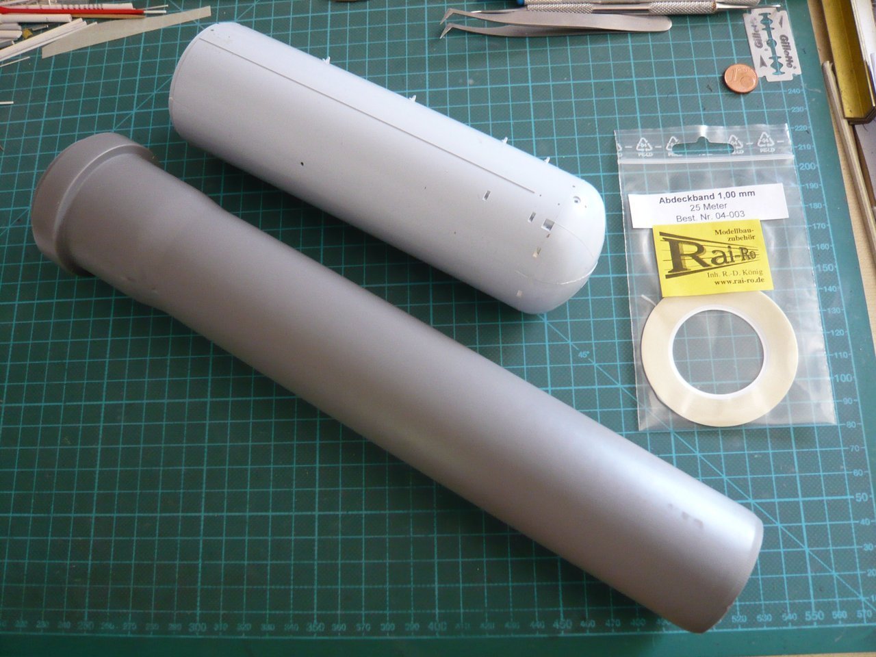
Let’s see what comes out of it …

4 Likes

Hey Brother…

Chuckle, I’m keeping your secret my friend, I’ll let it unfold by itself and yourself…

Good to see you posting the process again though…

Elmer

Okay Brother, I hope you can be as silent as the grave, so simply enjoy.

Hello Friends of the Rings,

since we were just now dealing with counting the rings on the LH2 Tank, here still comes with the Aft Dome the still missing ET end.

As the trained eye can see on this photo, which has already been shown several times, the rings on the Aft Dome are significantly wider than those on the front part of the LH2 Tank, although their curvature is barely visible, even in Hi-Res. https://www.britmodeller.com/forums/public/style_emoticons/default/blink.gif


Source: forum.nasaspaceflight.com (Jester)
Nevertheless, I tried to count these rings, whereby I came only with difficulty to 14 rings.

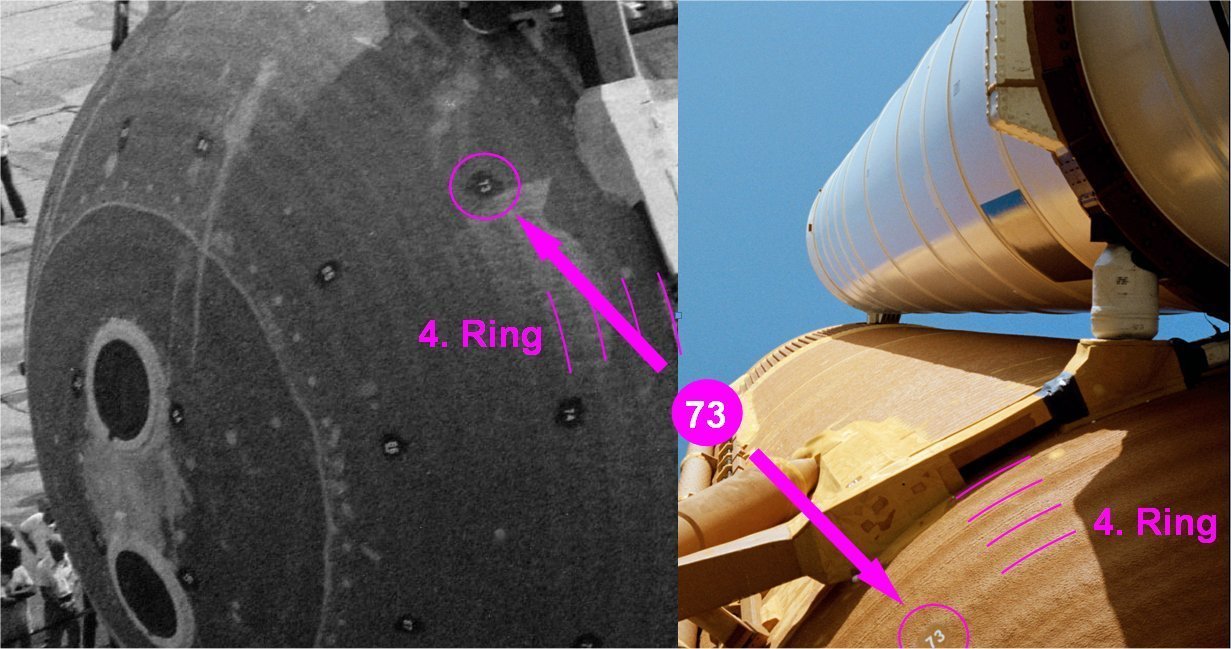
With the reference dimension of the front ring width of 1,3 mm, this results in a width of the rings on the Aft Dome of around 2 mm. The arrow in this picture indicates a small, but fine detail, which lies on the 4th ring, but what can be identified only in the Hi-Res-Zoom. https://forum.raumfahrer.net/Smileys/yabb/huh.gif

Therefore, here again in the left part of the picture an enlargement can be seen, on which one can recognize the number 73. And this number reminded me of the already multiply shown photo in the right part of the ET-8 of the STS-6, on which one can see the bulge of the Rings on the Aft Dome very nice, whereby the number 73 is also sitting on the 4th ring.

Thereby the counting of the rings is finished, at least on the LH2 Tank.

But as we know by now, on the LO2 Tank there are also such rings, or bands after my earlier terminology,


Source: georgesrockets.com

which I’m already was starting to count earlier,


Source: retropaceimages.com (STS-6)

what I can now check again from today’s perspective, because this would be the starting point for Michael Key’s 3D modeling, if he would get still involved with it.

4 Likes

Hi everybody,

in my search for more Hi-Res photos of the ET-8, I came across another great Rollout photo in NSF, even though with a laughing and a crying eye. :crying:

At first glance, one can still see no details at the Intertank in this resolution, but the picture is also from the thread Michoud: Best of External Tank - Hi-Res Images by Jester, and that’s why the zoom finally provides information about the so far hidden detail structure of the Thrust Panel, which surprised me quite a bit. https://forum.raumfahrer.net/Smileys/yabb/undecided.gif


Source: forum.nasaspaceflight.com (Jester)

Thereon one can clearly see that these panels of the first LWTs had no circumferential rings and bars, how I let them modeled by Michael Key for my IT. https://forum.raumfahrer.net/Smileys/yabb/rolleyes.gif

That means that the Intertank, which was modeled by Michael Key for me and since then offered by Shapeways, is no LWT-IT but an early SLWT-IT.

My mistake was that at that time I was too inspired by the 3D Intertank of my ARC friend Bill (niart17) and had not researched thoroughly enough.

Thus, this is another example of the “curse” of the late pictures, one could almost say, what I had already happened one time at the very beginning, only this time with the difference that I have surprised myself.

BTW, even in this photo one could already see this Rib structure without the circumferential rings in the zoom. https://forum.raumfahrer.net/Smileys/yabb/huh.gif


Source: forum.nasaspaceflight.com (Jester)

And also my only STS-6 photo with a view of the Thrust Panel actually indicated that already, although I was not sure yet.


Source: forum/nasaspaceflight.com (woods170)

Anyway, now I know about it and just have to think about how I handle it now.

As you may remember, my two ITs look like that, whereby I really liked these Thrust Panels.

But these seven rings and small bars did not exist on the ET-8 at the STS-6 and are therefore out of place.

These rings existed only since the transition to the SLWTs since STS-91, but were then left out again since STS-122.

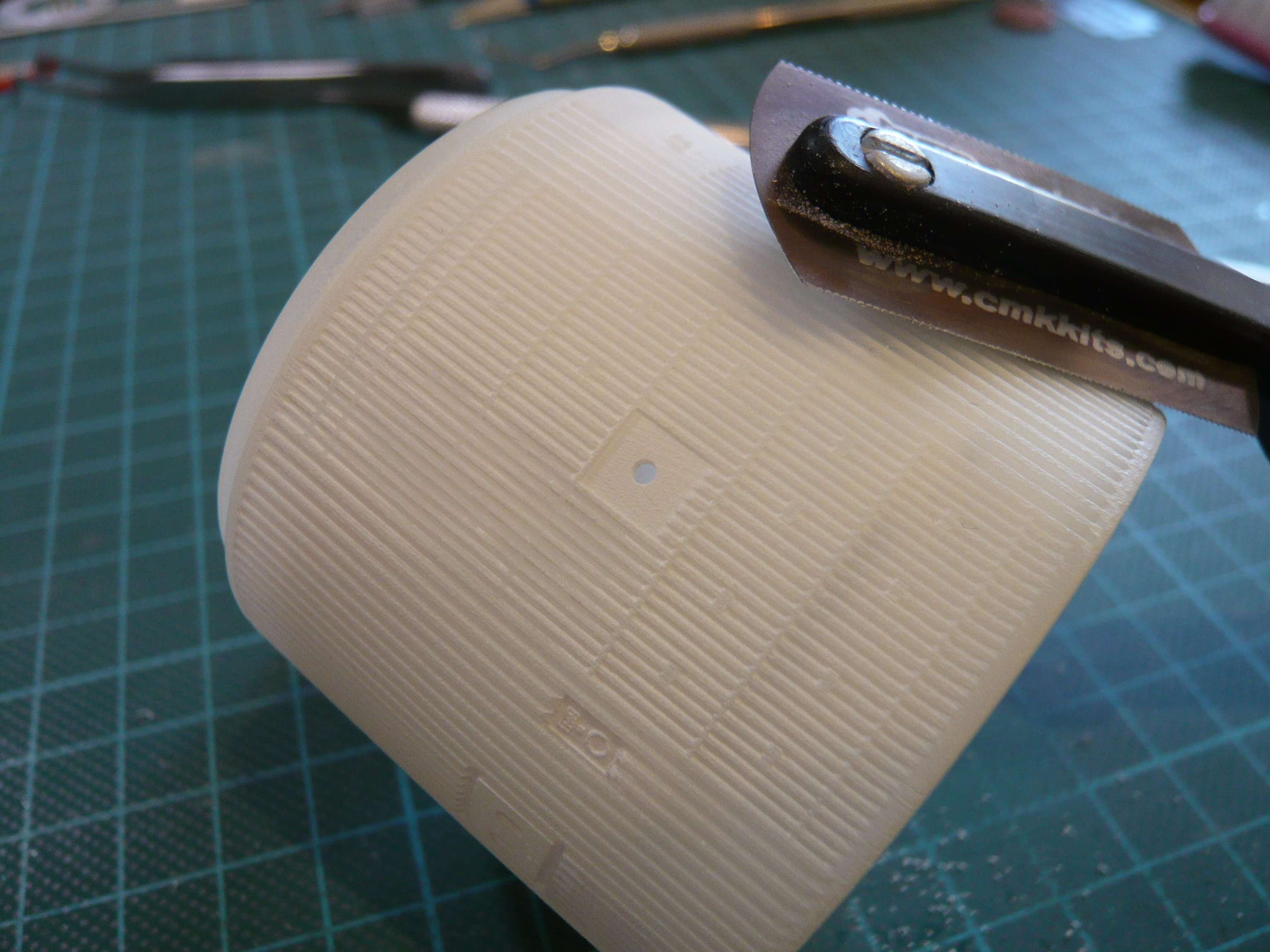
What is to do now? But anyone who knows me a bit closer, knows that I cannot be satisfied with that, https://www.britmodeller.com/forums/uploads/emoticons/default_fraidnot.gif which is why I was looking for a workable solution. And since the grooves between the ribs are very narrow and flat, my mini-saw of CMK (cmkkits.com), was the perfect choice, which is only 0,1 mm thick,
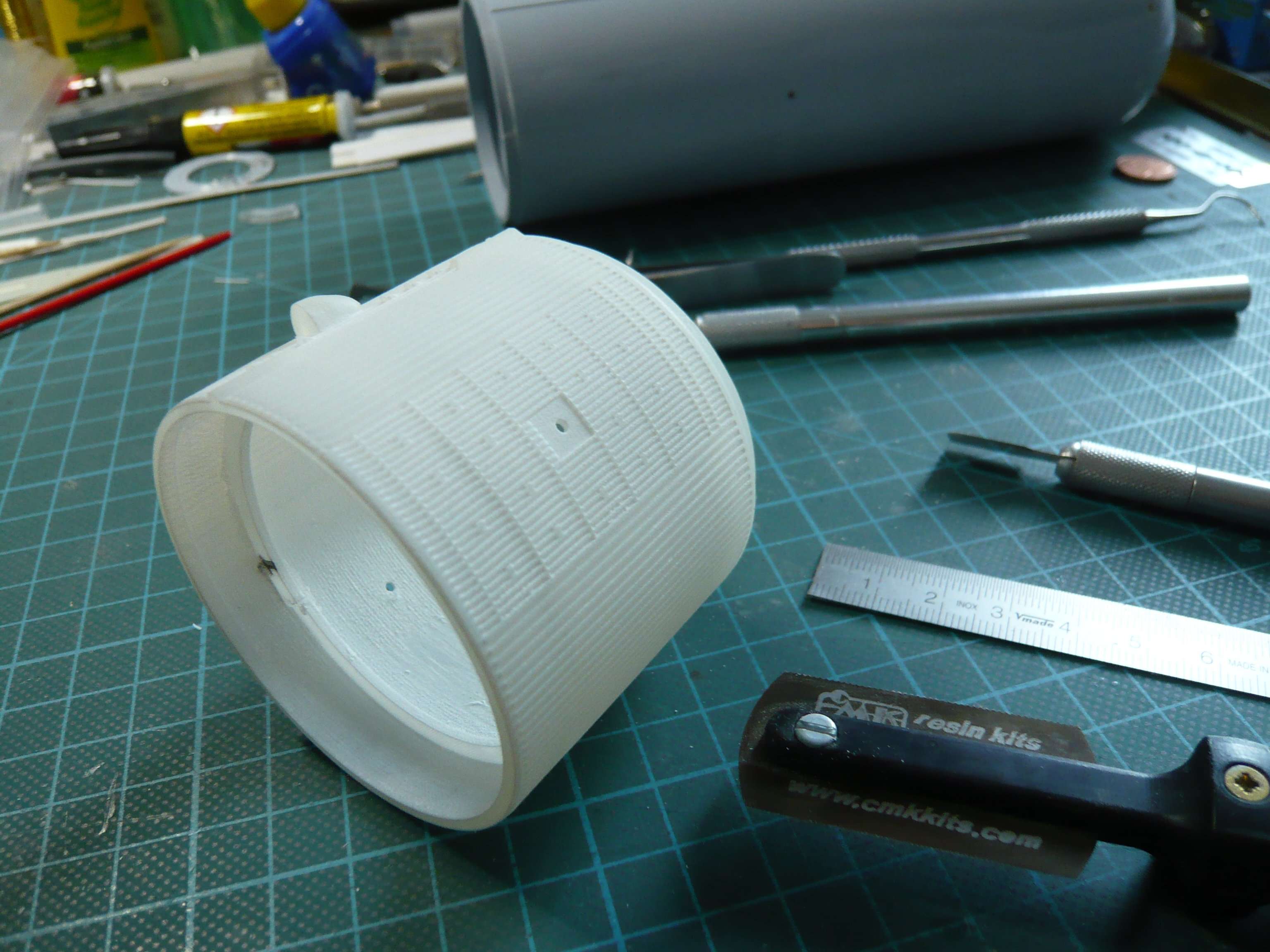
With that, I carefully removed the bars between the grooves, which is cumbersome and requires the utmost caution, but is ultimately feasible, which at least my first test on a wasted IT has shown. And with the steel ruler one can then even later smoothen something.

In principle, a modification of Michael Key’s 3D model would be possible, but the master is currently absent, and if I could get it that way, it would be okay and also cheaper.

Consequently I’ll probably have to bite the bullet and try to get it right on my Stack-IT, toi, toi, toi!!!

5 Likes

Really enjoying your work. I wanted to share a photo that I had taken at the same rollout event at Michoud. All the best- Stuart (ps- I will PM you some other pictures that I found)

2 Likes

Thanks, Stuart, for these great ET-8 photos from the rollout back then, in MAF. https://www.britmodeller.com/forums/public/style_emoticons/default/bow.gif When and for how long did you work there?
Your firsthand color photos are invaluable to me, as they show the ET from different perspectives, revealing various new details, which I value highly because I’m very detail-oriented. Please keep in touch my friend if I need your help again.

2 Likes

Hello everybody,

meanwhile, the 0,75 mm masking tape has arrived, whereby I was lucky and got the last role.

The 0,5 mm tape is unfortunately not available at this dealer, as it is no longer offered by his source in England, https://forum.raumfahrer.net/Smileys/yabb/rolleyes.gif which is why I have ordered it now in the Sockelshop, where even 0,3 mm tape is offered.

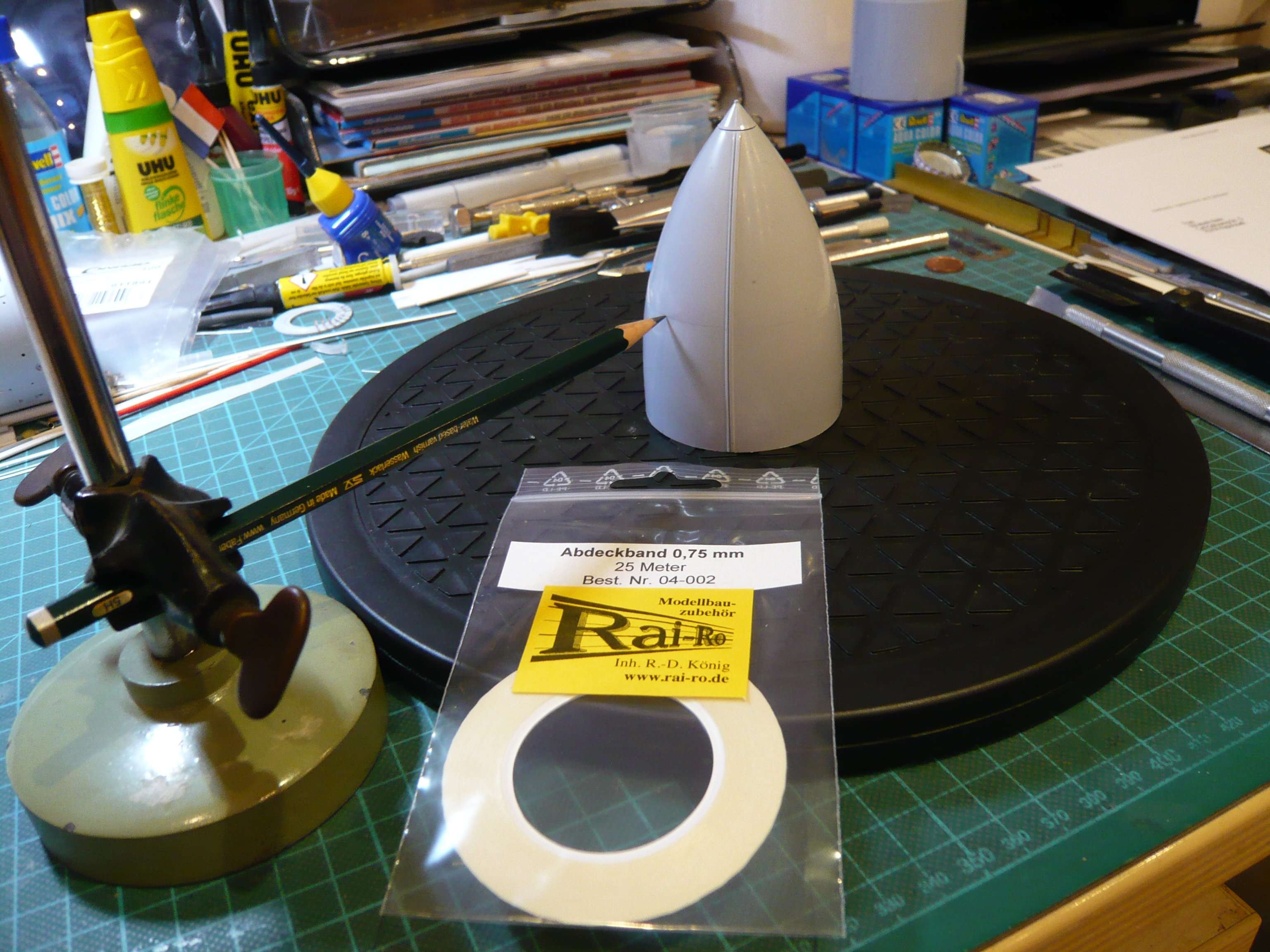
Then I tried the 0,75 mm tape on the LO2 Tank to see if or how it sticks to the curved surface.

For this I have marked an orientation line and then glued the tape next to it, which is quite feasible, as it clings well to the curvature.

If I then have the intended 0,5 mm tape as a spacer, then I can make the test on the ET dummy, whereby I would need to use 1 mm tape,

since the 25 m of the 0,75 mm tape would be needed almost completely for the 130 rings on the LH2 Tank and are reserved for it.

5 Likes

Another top update highlighting the value and importance of detailed research.

1 Like

Hi everyone,

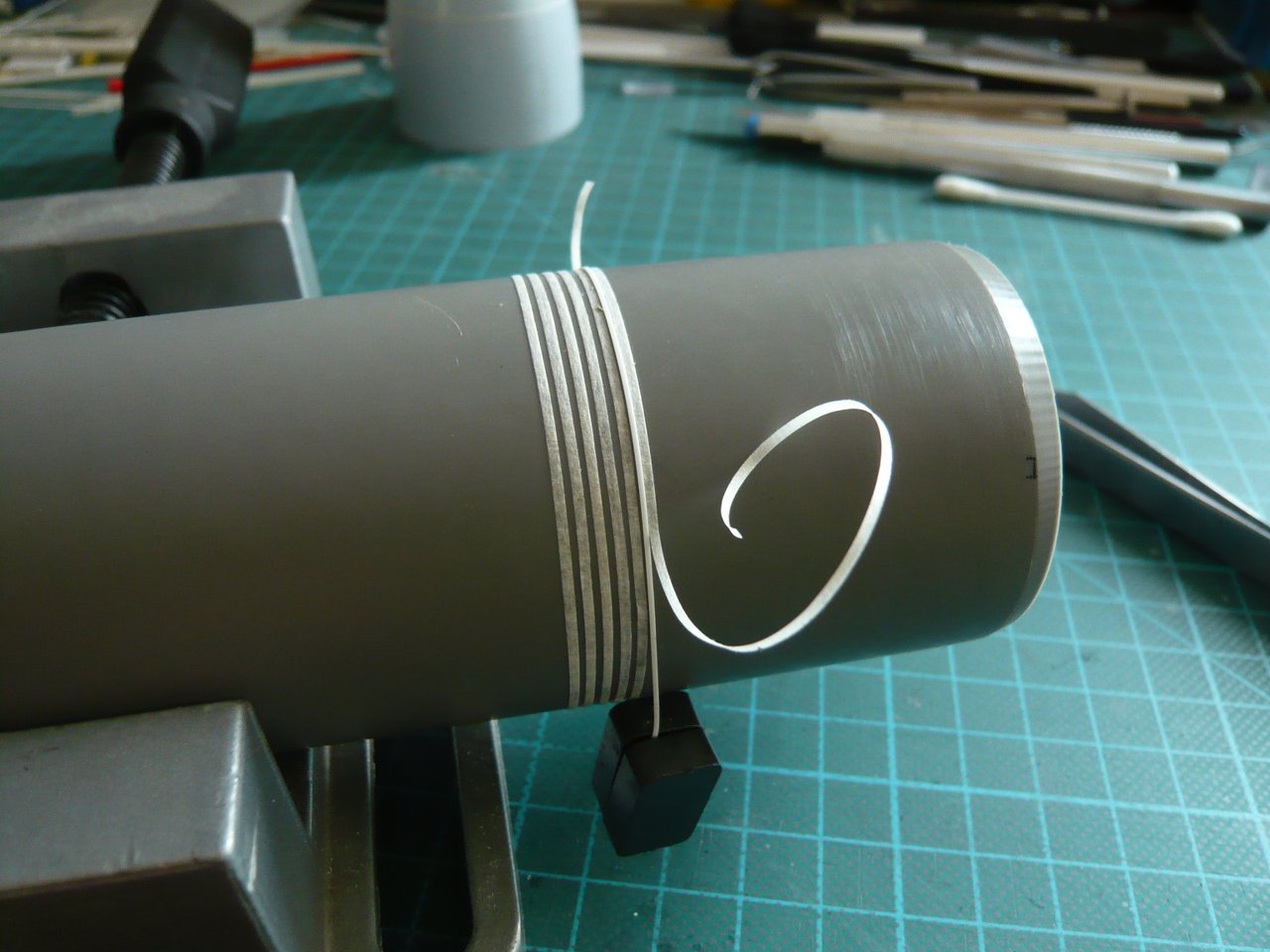
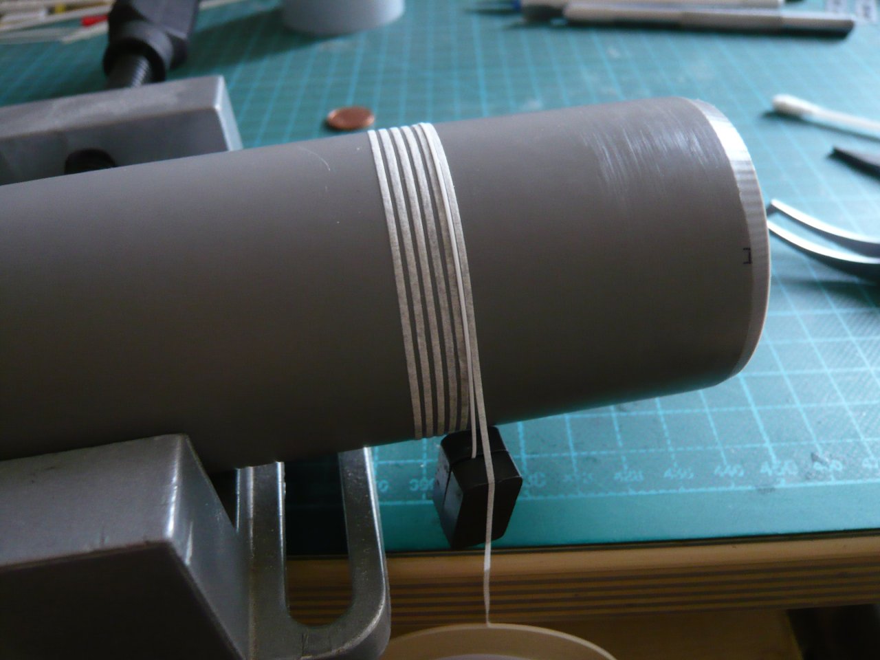
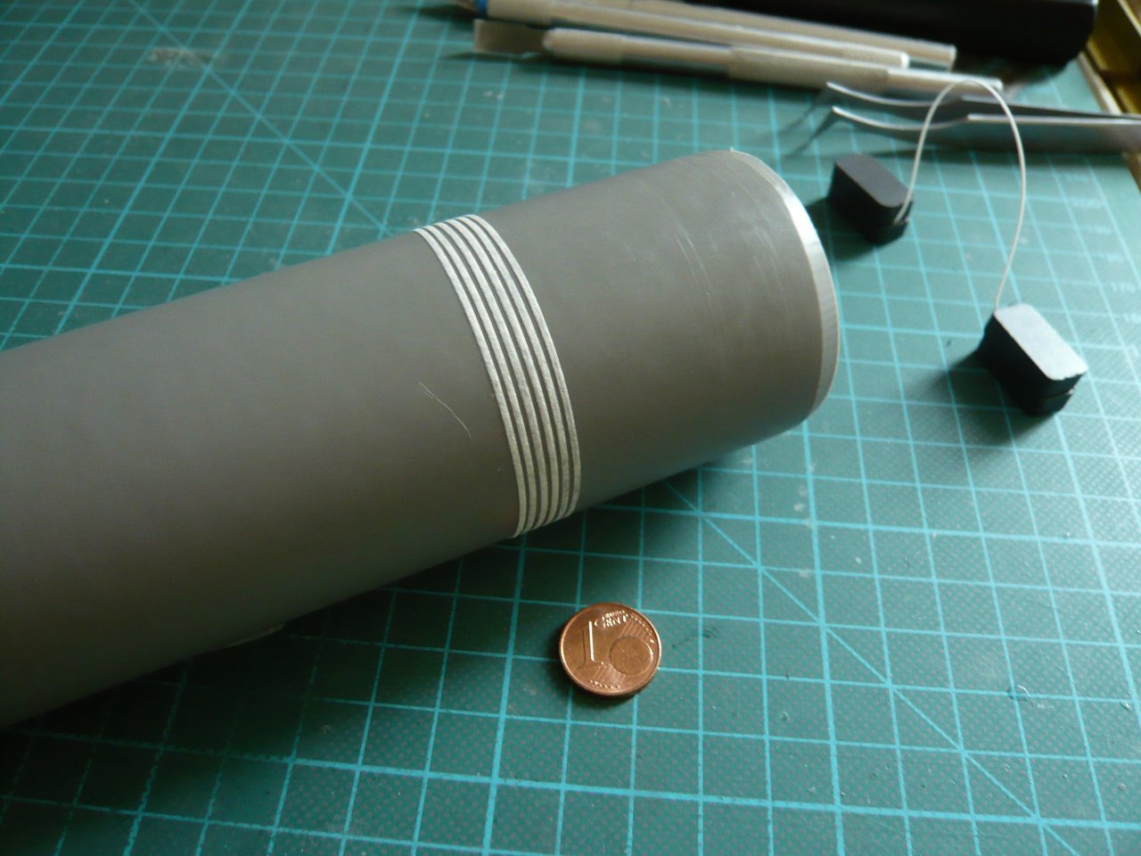
today I glued the first few tape rings of the 1 mm tape onto the ET dummy, but that was not for the faint of heart. https://www.britmodeller.com/forums/uploads/emoticons/default_fraidnot.gif

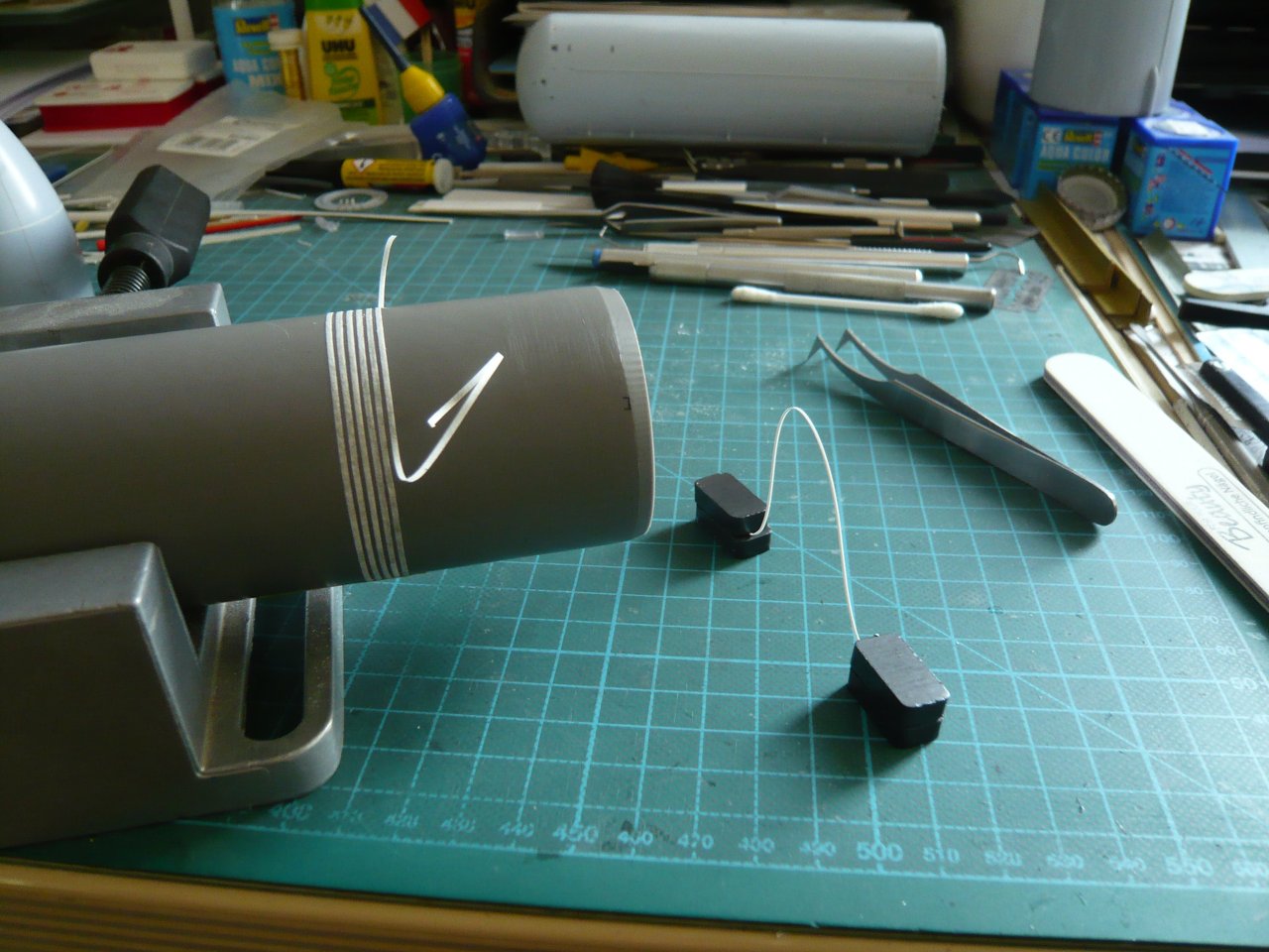
Since I still haven’t got the 0,5 mm tape as a spacer, I have taken an Evergreen Strip 0,25 mm x 0,5 mm, whereby the difficulty is to position this very thin strip around the tube, in order to stick the 1 mm tape strip beside it.

After having tested and rejected some holding methods, I came up with this Magnet sling, wherefore I clamped the strip at both ends between two small magnets and put it over the tube, which may seem adventurous, https://images.raumfahrer.net/up037692.gif

but still have worked.

And in a similar way I would now have to glue 170 of such strips in case of emergency onto the LH2 Tank, whereby the 0,5 mm tape as a spacer should be a great relief.
And to such an emergency I really have to adjust myself now, because Michael Key today has given me a knock-back for reasons of time.

He means that he has only little time and would need it to spend on projects that are financially worthwhile for him. He would have the feeling that only the front ET part (LO2 Tank) would take a lot of development time, with the prospect, possibly to be able to sell only a few of them. https://forum.raumfahrer.net/Smileys/yabb/huh.gif

He had also hoped that the IT for the STS-135 SLWT for my ARC friend Michael (crowe-t) would be a quick and easy conversion, but also that was turned into a time-consuming project with several modifications.

Unfortunately, I have to accept his decision, so I will now fully be focused on my Scratch variant with those tape-rings and by using the Flour technique for the SOFI texture.

6 Likes

Hello everybody,

let’s go on with the analysis of the SOFI Rings.

Since my first count of the rings on the LO2 Tank on this ET-8 photo seemed to be a bit vague and upto the top was incomplete anyway due to the lack of resolution, https://forum.raumfahrer.net/Smileys/yabb/rolleyes.gif


Source: retropaceimages.com (STS-6)

I repeated the count again today on this new (old) photo of the ET-8 because its resolution is much better.


Source: forum.nasaspaceflight.com (Jester)

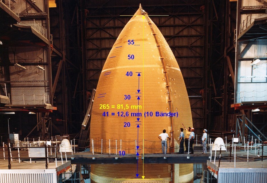
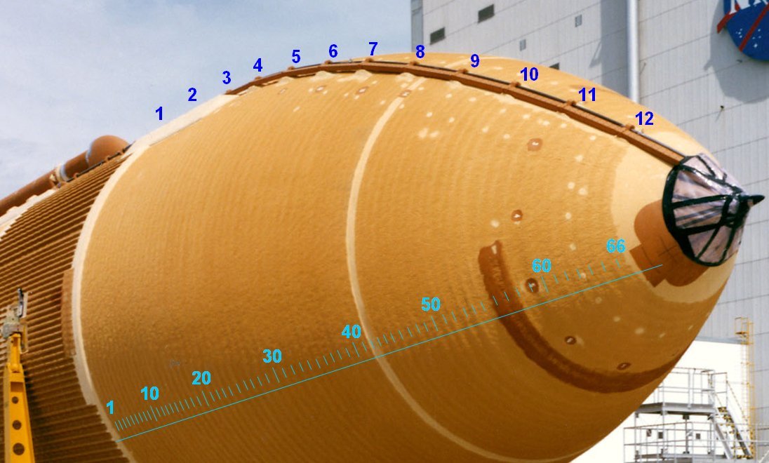
For this I had set the zoom mode (MS Word) to 250%, where one can see the rings pretty well, and came up to 66 rings.

And that would have to be roughly the area, where at the Airfix LO2 Tank, which is 81,5 mm long, the front Nose cone cap is put on, the tip of which unfortunately broken several times and must be replaced. https://forum.raumfahrer.net/Smileys/yabb/huh.gif

With this the determination of the ring widths was made, or in slightly more complicated expert wording, the Valley-to-Valley distances:

81,5 mm : 66 = 1,2 mm, which agrees well with the value of 1,3 mm for the rings determined on the LH2 Tank, and would match also from the optical impression.

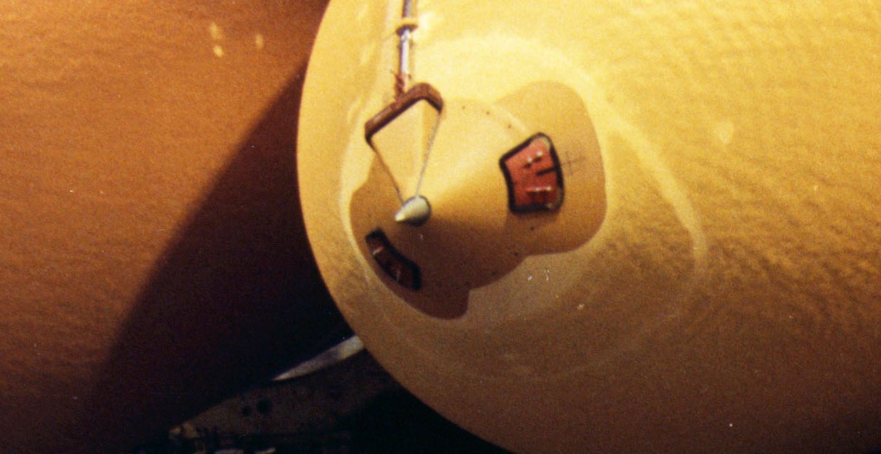
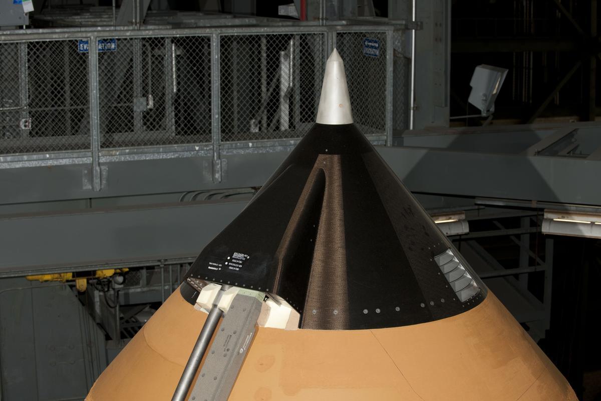
Unfortunately, in the photo above, the Nose cone is covered with foil, but in the following image one can see different cones on LWTs of the first generation (1988), whose shape is interesting for scratching,


Soure: forum.nasaspaceflight.com (Jester)

and therefore here once more a slightly larger section.

And already thereon you can see that the Nose cones of the LWTs looked a bit different,


Source: californiasciencecenter.org

than one knows them in Graphite composite version from the last missions with SLWTs.

4 Likes

Hello everybody,

there are enjoyable news.

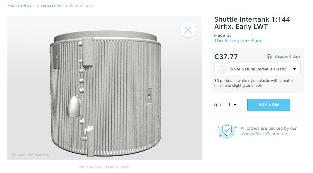
Fortunately Michael Key had compassion for me and has modified his 3D model of the IT, so that I can save me the painstaking post-processing of the Thrust Panels by using my mini-saw, which I had tested about a week ago.

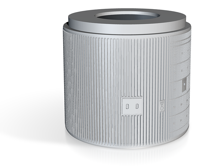
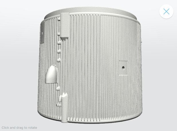
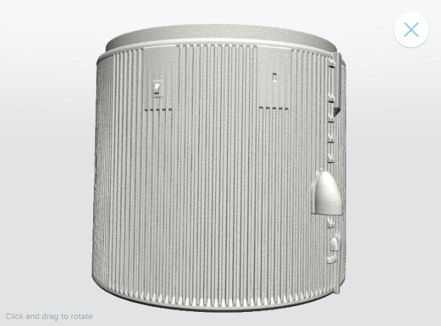
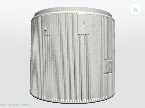
Here is his 3D Update of the flown STS-6 tank (ET-8), which is now to be found at Shapeways under its new name Early LWT.


Source: Shapeways (The Aerospace Place)

Before this action, I noticed still just in time that at his previous model still lacked two small details that I had previously overlooked. https://forum.raumfahrer.net/Smileys/yabb/rolleyes.gif

So far I had mostly only ET photos of the side facing the shuttle, but hardly any of the opposite side.


Source: retrospaceimages.com (J. L. Pickering)

There I was always fixated only on the Access Door and the Carrier Plate Assembly.

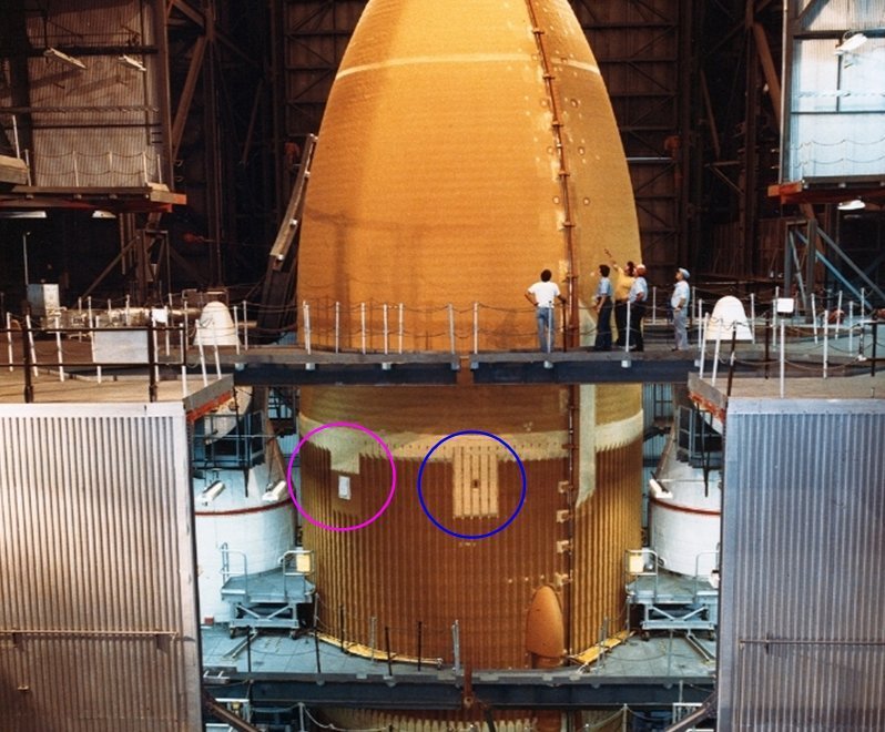
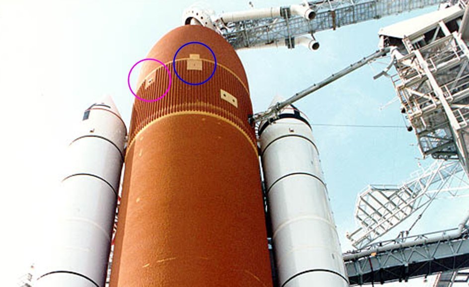
But also on the back there are exactly opposite the same two items as on the front side, as one can see in this photo from George Gassaway. The pink circle involves the RSS Antenna]() and the blue circle an Aerodynamic Vent.


Source: georgesrockets.com

And exactly these two items were missing on the back of my IT, which of course could not stay that way, https://www.britmodeller.com/forums/uploads/emoticons/default_fraidnot.gif wherefore I should have to scratch them if necessary. https://forum.raumfahrer.net/Smileys/yabb/huh.gif

But these two things Michael Key has kindly complemented next to the modification of the Thrust Panel Ribs, so that the IT now is perfectly matching the Early LWT.


Source: Shapeways (The Aerospace Place)

And this IT I have ordered now once more in WSF and will probably use it in this form for my ET.

BTW, the IT modeled for my ARC friend Mike (crowe-t) for his STS-135 (ET-138) Shuttle stack is offered at Shapeways under Late SLWT.

2 Likes