Well yes, I suppose that explains my slow build rate!
An early MASSTER M60 would have worked well I guess, but the IDF die is cast so far, with an Urdan cupola already in place… 

Good news on the fit of the M103 parts, but I’m not looking forward to those tracks!
I hope to make the Yeovil show, so look forward to seeing where these two are!
3 Likes
Nice build Terry, nice build.
Re the tracks: I baulked at the kit ones - 6 x construction movements to make one track link (I might be wrong, I just couldn’t face it) and went with some AFV Club T97E2 ones; they were a pain for sure with 2 x sink marks on every link, but were relatively simple to make. Fitting them will be a bit of a test which is why I’m having a break from them at the moment. besides, I’ve got to apply all the usual clag I do to the hull/suspension using model railway flock and the like.
See you at Yeovil then! If not finished I’ll still display them say, in primer as a WIP.
2 Likes
Finally got caught up with this Brian. Very nice indeed. Youre not joking about box size😶
1 Like
Yeah, I reckon if my wife kicks me out I could live in it - and have room for my car.
4 Likes
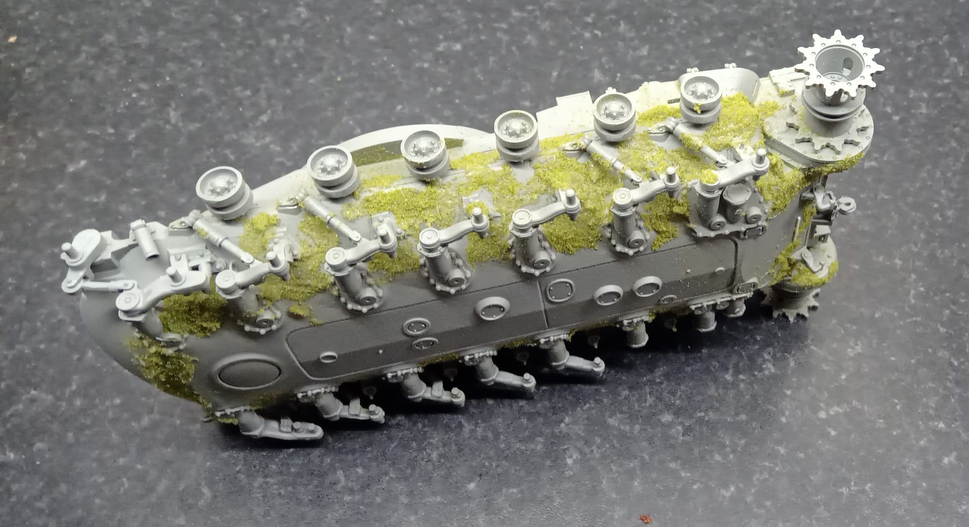
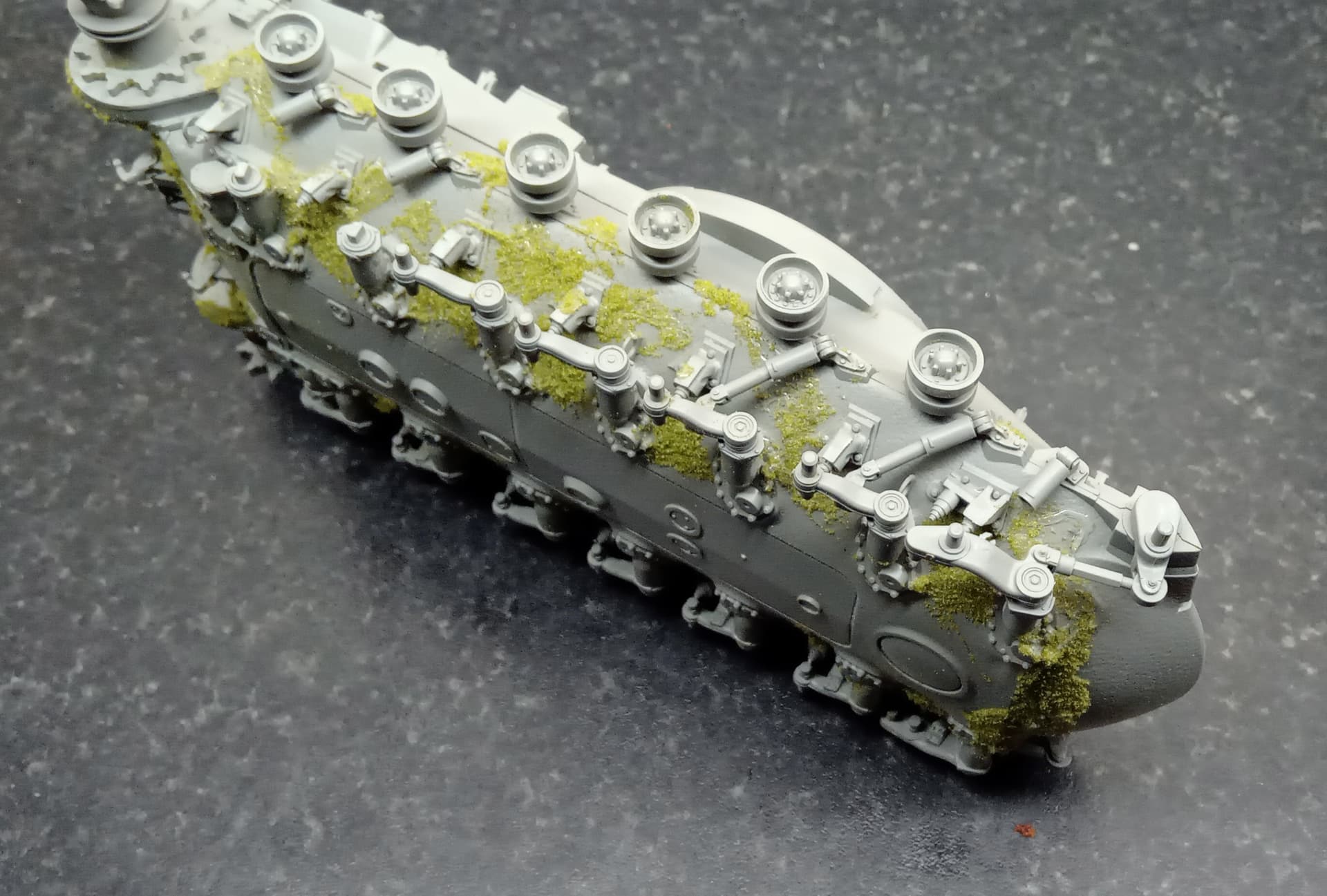
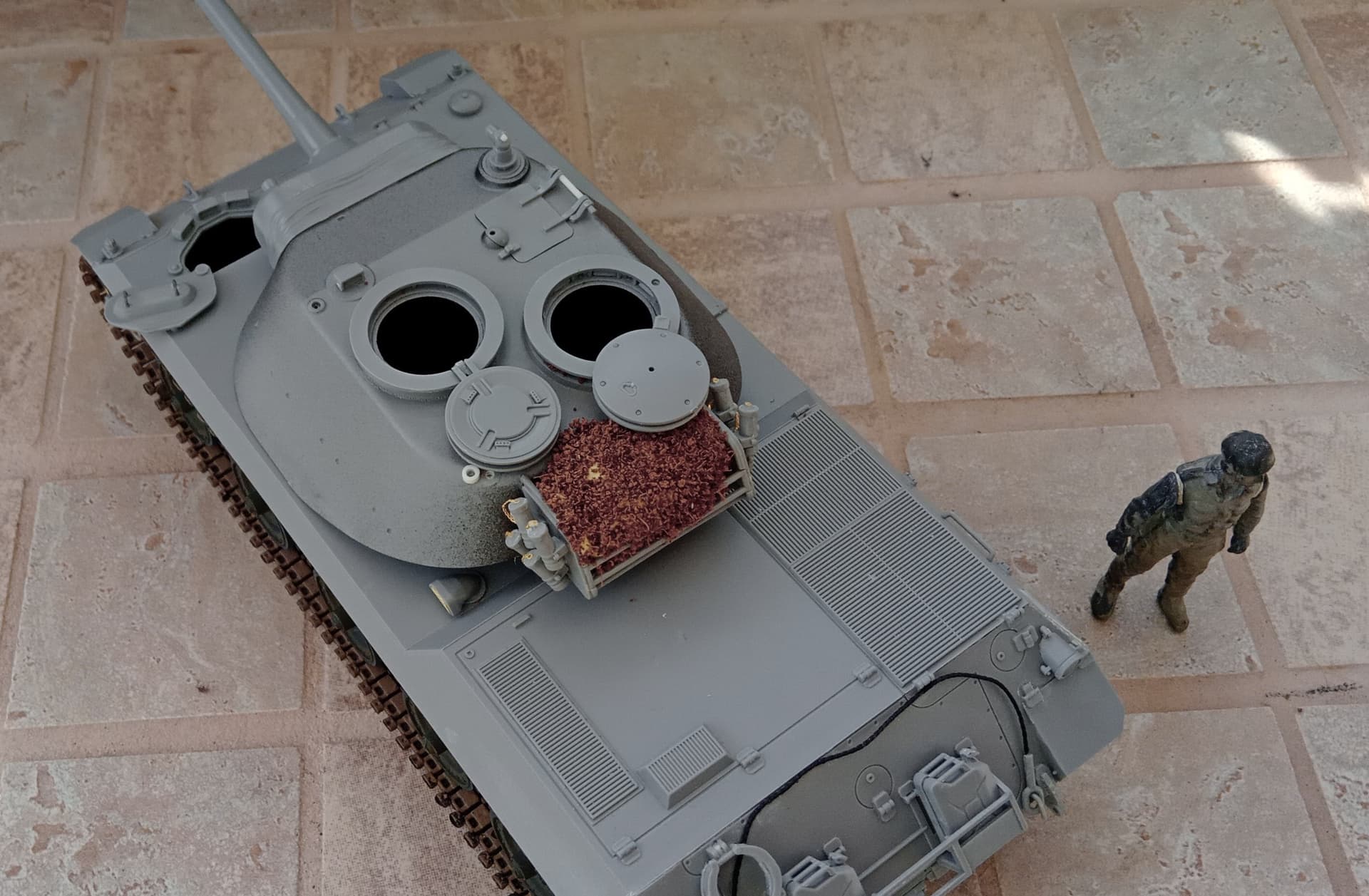
As mentioned above, an application of model railway flock to represent all the clag that builds up on AFVs in the field; it looks a bit startling in lime green but that will soon disappear under some dark earth:
Also noticeable is the complexity of the suspension, missing some components whilst I apply said clag. I’ll have to replace those and adjust carefully when I attach the tracks - always a fraught business with me. Coordinating fitting with the front idler often conspires against me(!)
5 Likes
Looking good there.
According to the tracking, the metal barrel and the RU 251 have left the airport……
Edited to add: In China.
1 Like
Excellent build so far Brian. That suspension does look very busy as you said.Great idea with the flocking material you’ve applied to the hull. I must have two huge boxes of the stuff from my railroad hobby days.
I also have a glut of projects waiting to be finished- who knows when they’ll be done.So many distractions!
1 Like
Gents,
Some good info and images on this vehicle here, Postwar German Experimental tanks | Secret Projects Forum, if not already known.
2 Likes
Thanks Kylie,
A pity the images are hidden behind a membership wall, however some useful stuff here, some/most of which ties in nicely with the backstory I’ve prepared when I finish the RU 251 and (what I call) the M103A2G and display them together.
2 Likes
Ah, yes, a minor technicality, & being a member, the images loaded for me.
3 Likes
Brilliant! But probably some time before we discover/access a walkaround of the RU 251.
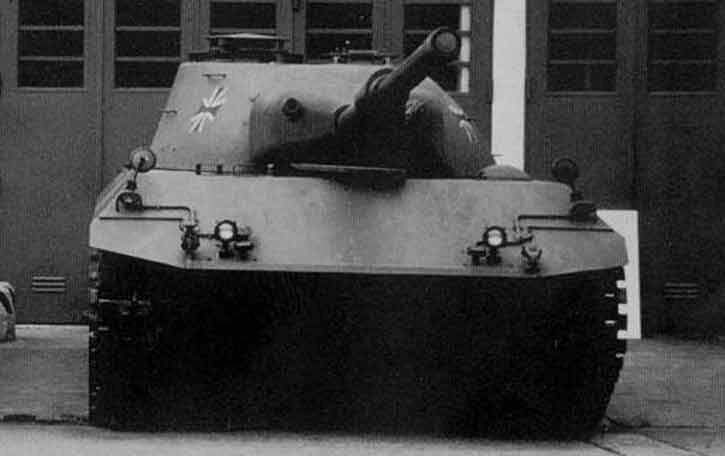
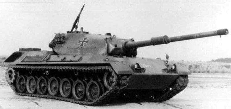
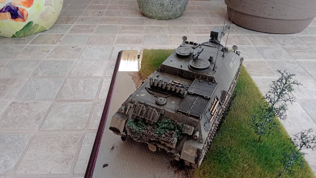
For instance, does anyone know where the exhaust is on the RU 251? I’m guessing that it’s the small box-shaped grilled-device towards the rear of the hull:
My logic based on the ultimate exhaust positioned on the Jagdpanzer Kanone.
5 Likes
The only drawback from a Recce point of view is that your exhaust gases will vent straight up giving a nice IR/thermal bloom … ? Whats the small outlet to the rear of the turret by the shovel ?
1 Like
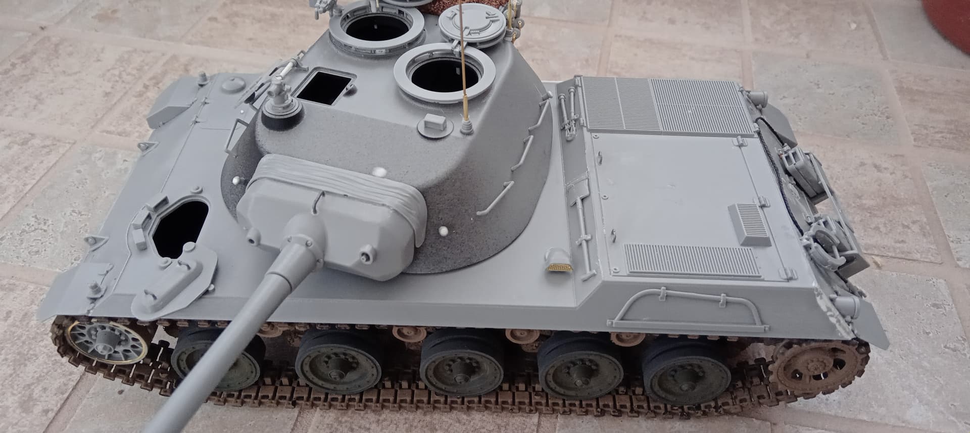
It could be an exhaust I grant you, but, I rather lean towards an NBC filter/intake.
I accept there would be an IR flare, up to a point given the IR detection kit of the time, but there was no TI kit back then. I ask as I need to know where to place my black pastels!
I have assumed that the exhaust would be on the hull rear as it was thus on the Jagdpanzer Kanone (the small circular device shown below).
Due to the ostensible commonality of design I’ve assumed therefore that any exhaust would be similarly placed; 'happy to be proved wrong! This is why we need a Walkaround soon - anyone live in Koblenz or wherever the real beast is?!
4 Likes
Yeah I suppose if the same pack were used then it would make sense that the layouts would mirror each other more or less …
1 Like
I think that’s what I’ll have to go with John; I would love that other outlet/intake (below) to be the exhaust as it’s just crying out for a smudge of black pastel. Until we get any details I suppose I can successfully blag it! After all, who’ll be able to gainsay me? (Famous last words).
With a fair wind, I should have it for Yeovilton; it may still be in primer but that’ll do, I hope.
4 Likes
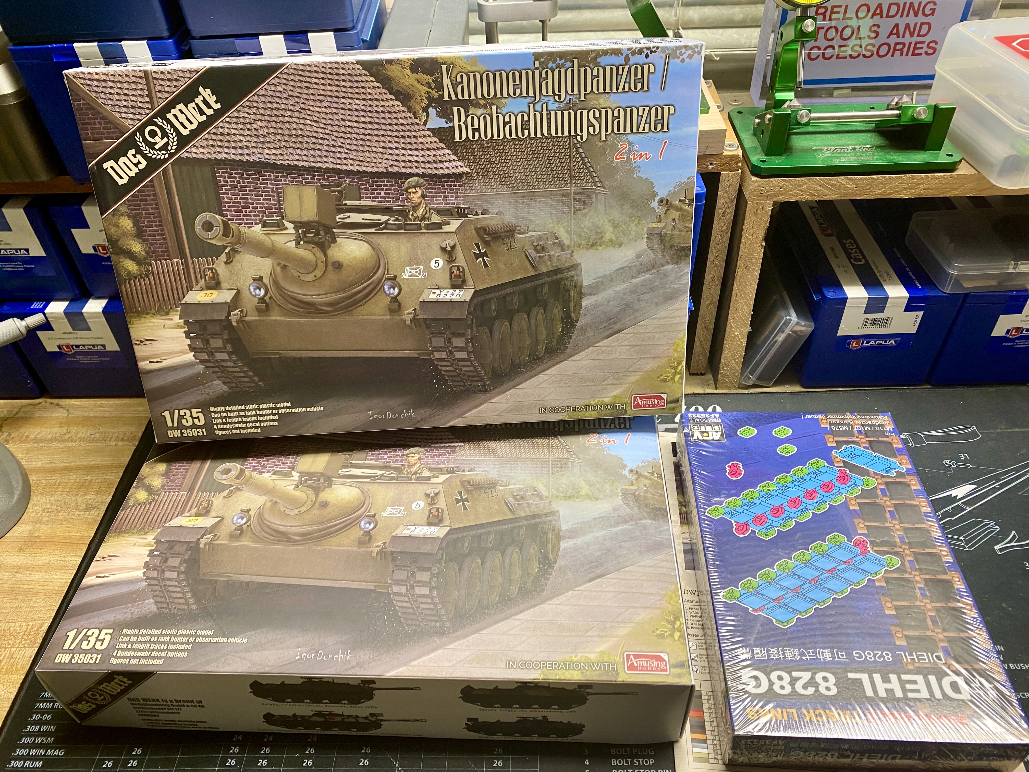
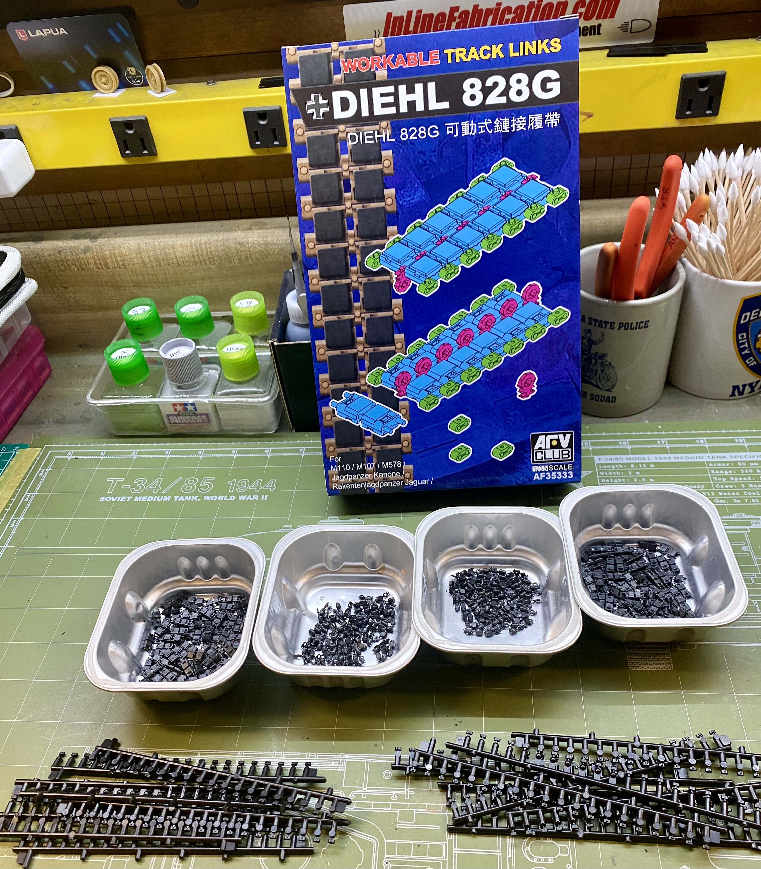
Here’s an interesting tidbit. I decided to slog the the AFV club Diehl 282G tracks in preparation for building my Das Werk/Amusing Hobby Kanonenjagdpanzer and Beobachtungspanzer kits.
There are 160 links total in the AFV Club Diehl track kit so I figured 80 per side, at least.
When I’d assembled 42 links or so, I decided to pull out the Kanonenjagdpanzer instructions and figure out how many links were called for in the kit per side. Knowing this was a link and length set up, I counted up the links and lengths and came up with 84 links per side.
“No way,” I thought, “This can’t be right because I’d need 168 links total per vehicle and get 160 links per AFV Club track kit.”
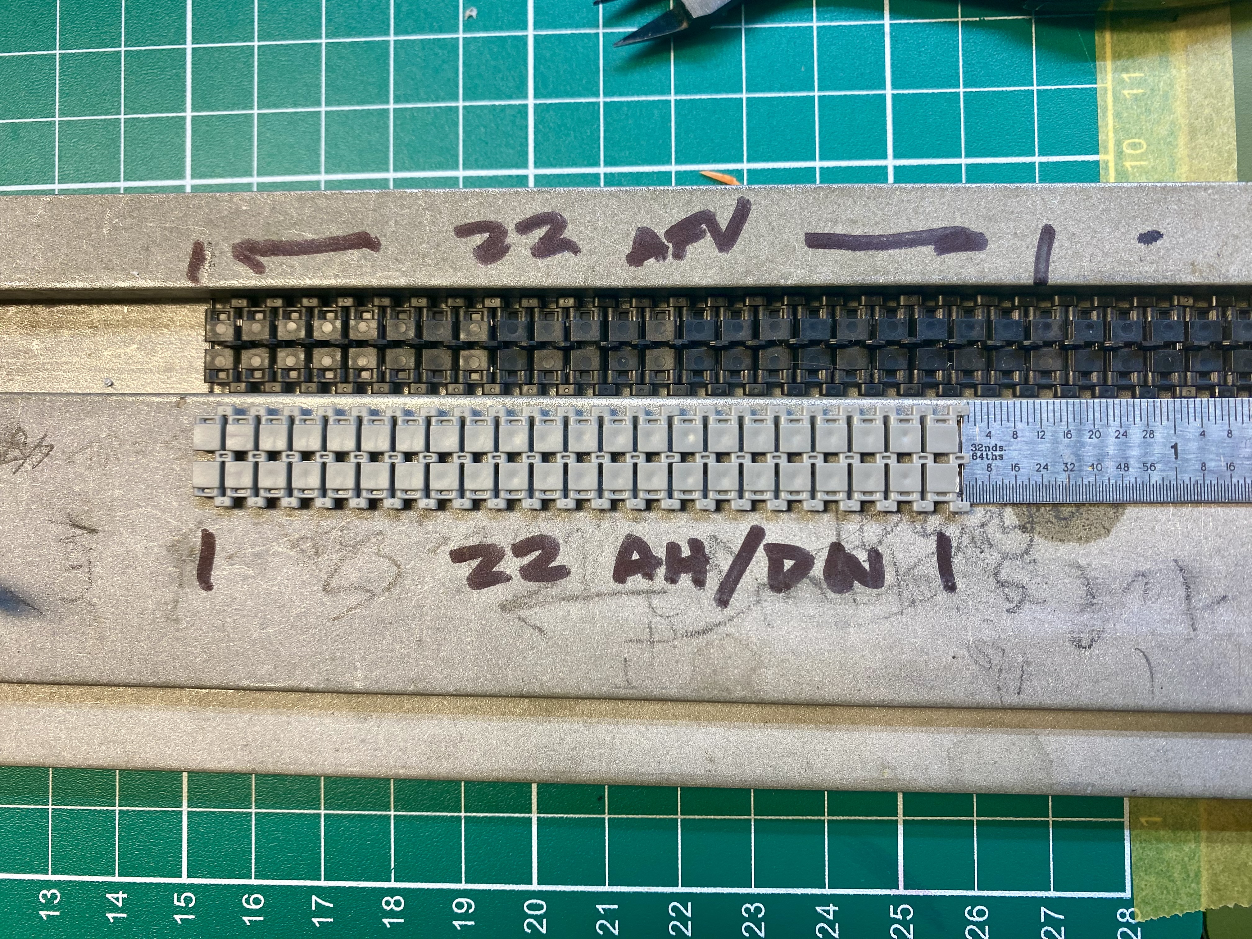
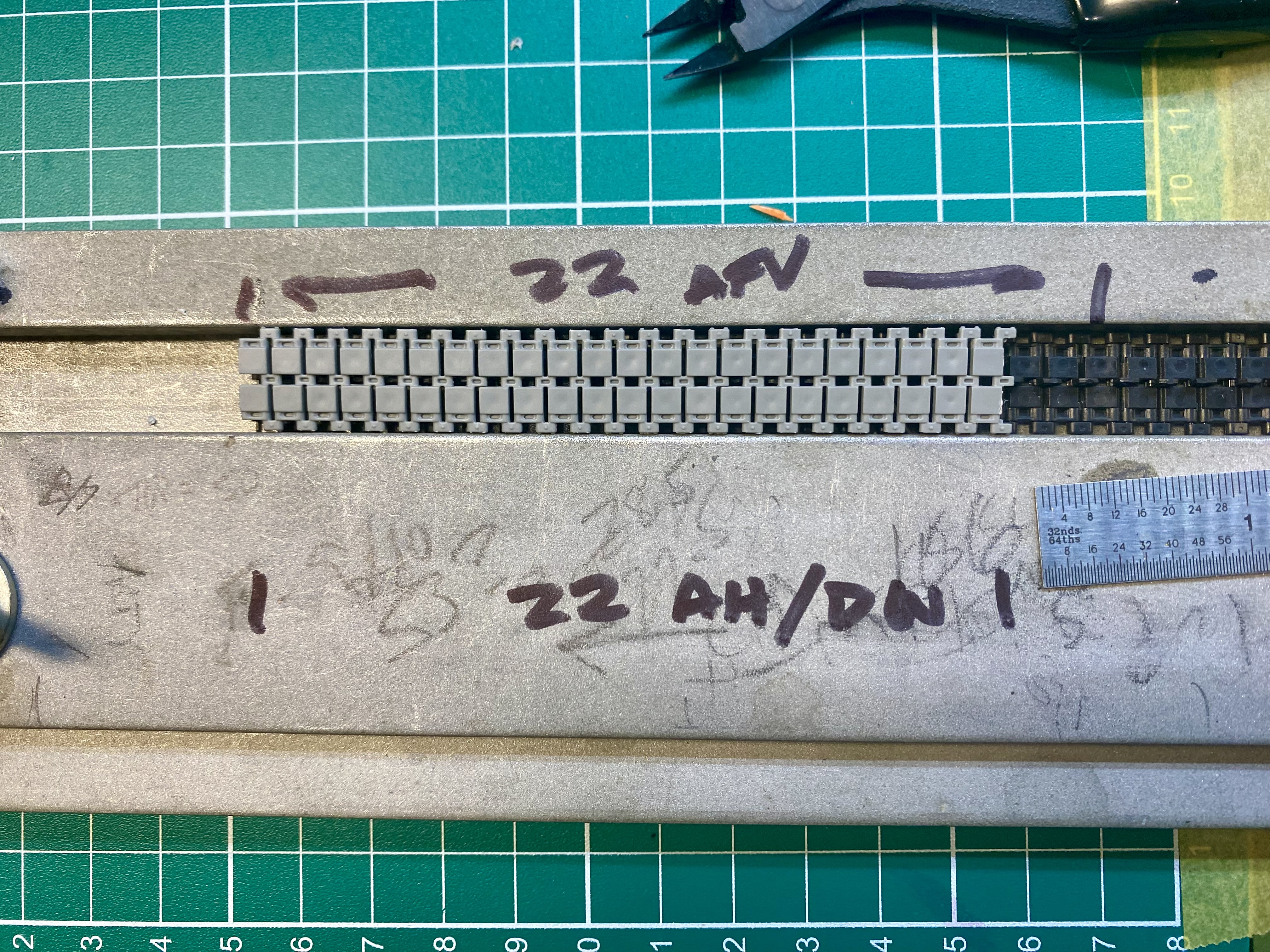
So I cut out a 22 link section from the DW/AH kit and compared it to the AFV Club tracks I’d already assembled in my ancient Squadron track jig.
22 Amusing Hobby/Das Werk links were 3/8in (.375in) shorter than the same number of AFV club links.
Not only that, but the AH tracks are also narrower.
It’s too late here to start screwing around with drive sprocket fitment.
Anyhow, I thought this would interest anyone who was considering AFV Diehl 282G tracks for this type of running gear.
Edited to add: you were absolutely right about cutting the long track section off the sprue. What a pain in the ass.
4 Likes
Thats a really helpful and interesting comparison Al. I don’t have my AH Kanonenjagdpanzer yet (picking it up Saturday hopefully), but will bear that in mind. Thanks for sharing that one!
2 Likes
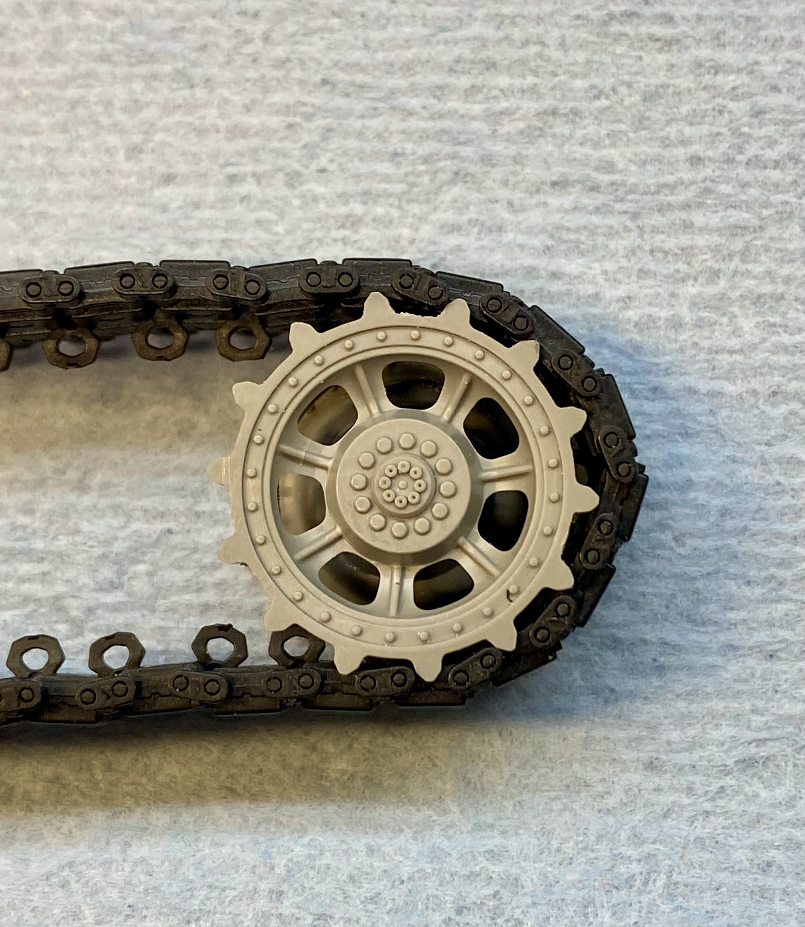
The AFV Club tracks will not fit without modifications that I’m not capable of.
2 Likes
Ut-oh. Pitch differential. You have to very carefully cut off all the sprocket teeth and glue them back on so they fit the track. Then putty and sand so it doesn’t show. I’ve done it before. It isn’t fun.
1 Like
Tricky since the teeth have to be evenly distributed and have to be evenly spaced around the whole circle.
Moving teeth on the “engaged” side could result in one less tooth (if lucky), the worst case is that 0.75 tooth needs to be removed.
One hypothetical solution is to add shims to the sprocket circumference between the teeth and then build up the tops of the teeth. Essentially increasing the diameter of the sprocket.