Something I bought 4 years ago especially for soldering:
It is a honeycomb plate with pins that go into the holes. Using the pins one can get any angle between parts to solder set and has both hands free to solder.
HTH,
Cheers
Angel
Something I bought 4 years ago especially for soldering:
It is a honeycomb plate with pins that go into the holes. Using the pins one can get any angle between parts to solder set and has both hands free to solder.
HTH,
Cheers
Angel
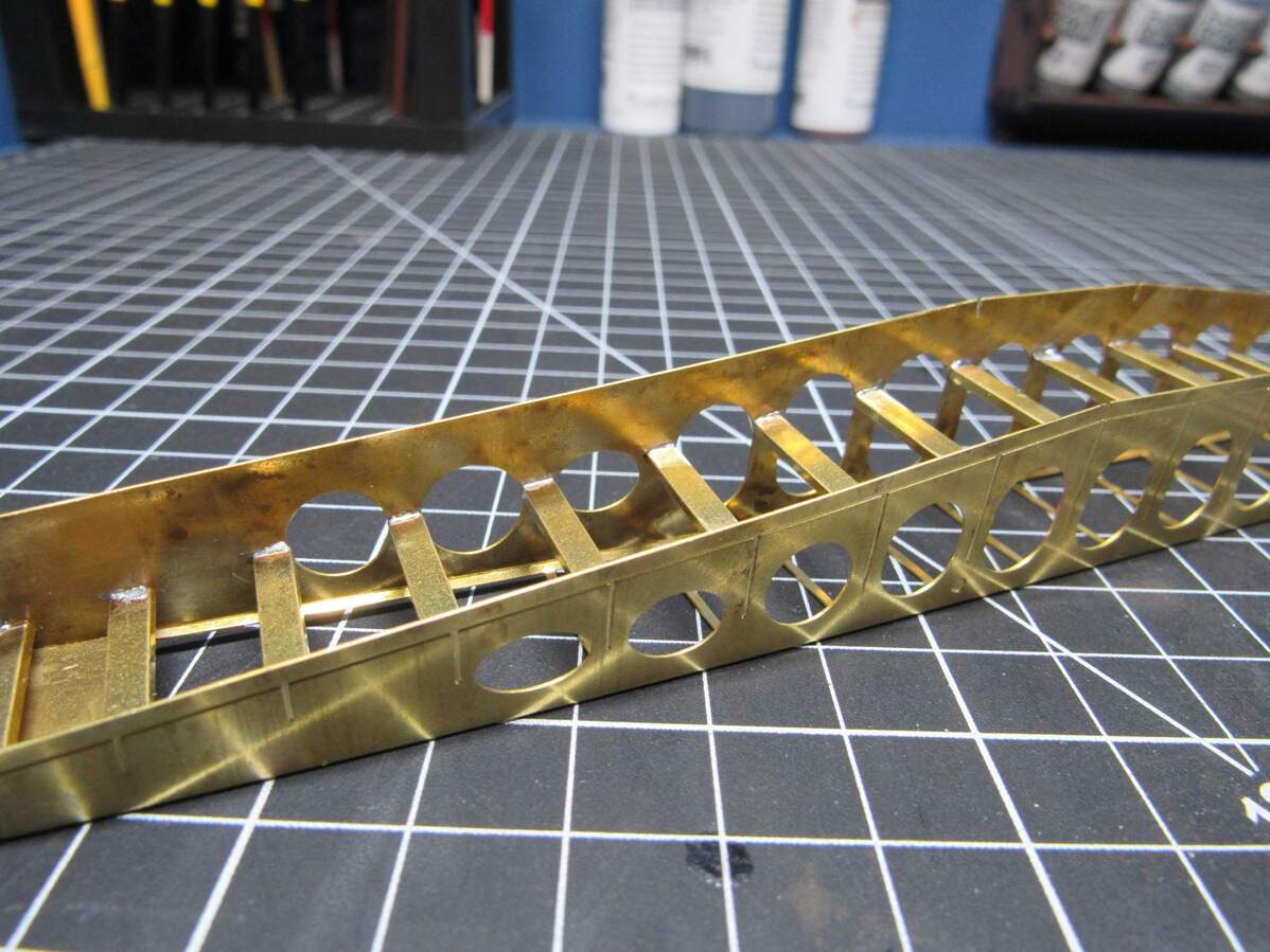
So looking at my soldering station, it’s only a 70 Watt. Figured it was acting as a giant heat sink, the brass is relatively thick too for PE standards at 0.3mm. I can even comfortably hold the bridging unit with my hand while soldering. I may give pre-tinning a shot, and I’ll keep the chisels in mind for when I get around to cleaning up. Think I’m gonna struggle along with my current soldering iron, hate to buy a new one… but now that I think of it, I do have a simple wall plug one laying around somewhere that I’ll have to look at.
Handling is actually pretty easy though. The flux I use is a sticky paste, helps keep parts in place and I can just drop in a rod of solder and it stays in place.
Edit: Wall plug one is 30 Watts, lol.
That could be very useful, currently using a block of wood that the PE slides all over
You wouldn’t happen to have one of those small butane powered torches?
Sometimes used for cooking to give a crispy burned surface to meat …
Gazillion different brands but they generally look like this:
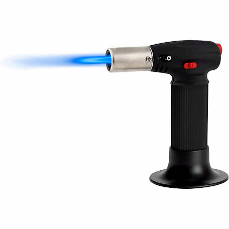
refill with standard lighter gas.
Using the kitchen stove as a general heat source could be another option unless there is a SWMBO that would get seriously upset …
I was actually thinking of that at work today. My mom has one, and as a kid I used to sneak off with it and burn action figures. Don’t have one, but the more I think about it, the more tempting it is. I do have a MAP gas torch for sweating pipes… but that might be overkill.
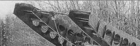
I powered on through for a couple hours tonight and managed to get the treads done on the 2nd unit, took my time and got a much cleaner result.
Gettin there
honestly, this looks like a good 3D printing job. hope you plan on marketing this as I’d like a couple
gary
Auto Cad is OK, but not as great as it’s been hyped to be. We tried it at work, and after a month it was removed forever. Just not friendly when moving to the next steps (loading it in a machine for one). We went back to an upgraded and customized system with a second completely different system that built a 3D model as you worked on the drawing. ($$$$). When we bitched they thought we were nuts. Then they saw it in real life and had a major change of heart.
Your project is very similar to a couple I did years ago. Only about twelve feet long. Steel was water jet cut and then welded together with home made jigs to get everything square. If you happy with Auto Cad and it works for; then of course use it.
gary
goto a store that sell electrical parts. They use a small pencil torch that they use for circut board work. Not expensive, also will light your cigar in a pinch
gar
It would require a sizeable printing bed, the bridging section is nearly 8" long. On the fence about marketing this too. Couldn’t market print files without testing them myself first and I don’t have a printer. Releasing as a PE kit would mean some labor in cutting the needed brass rod, casting some resin parts etc… Part of me wants to just release the design files out into the world when done. Guess we’ll see when I get there, and if there’s enough interest to warrant the effort.
Really just using it as it’s what I have on hand. Does have its quirks, but so far it’s working well for these projects. More of a 3D guy to begin with, so I don’t have much to compare it with.
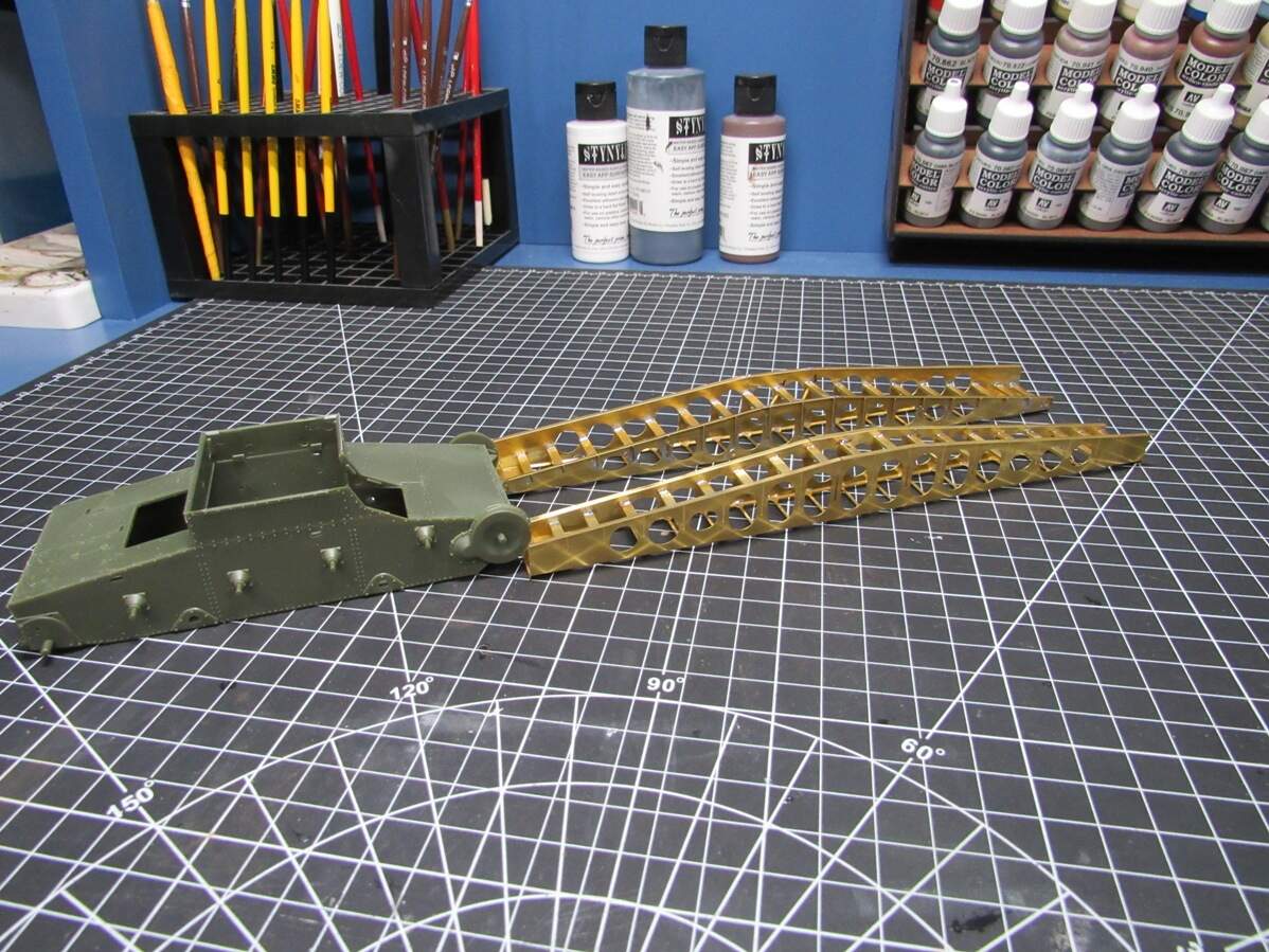
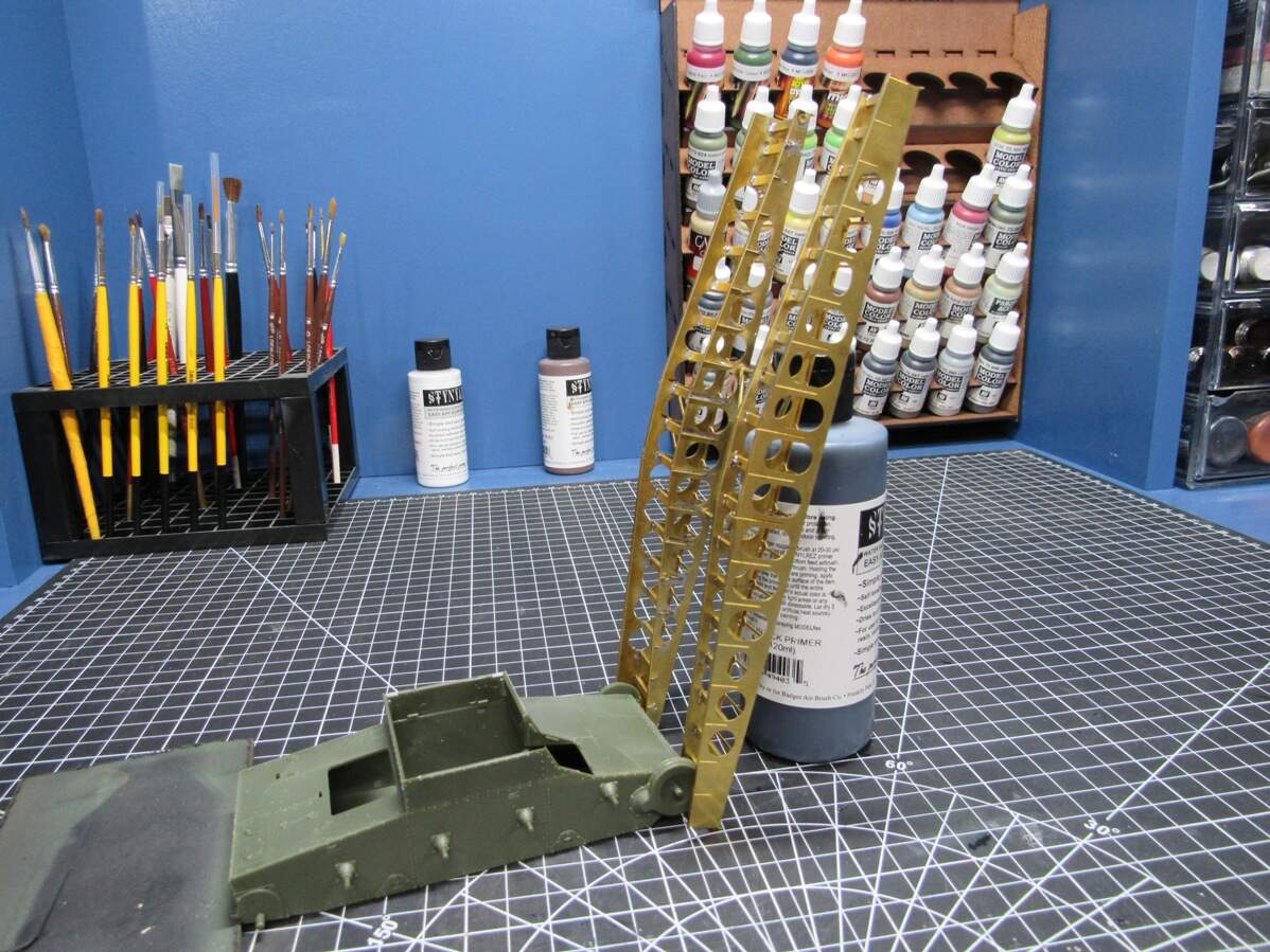
Here it is with the base kit for scale,
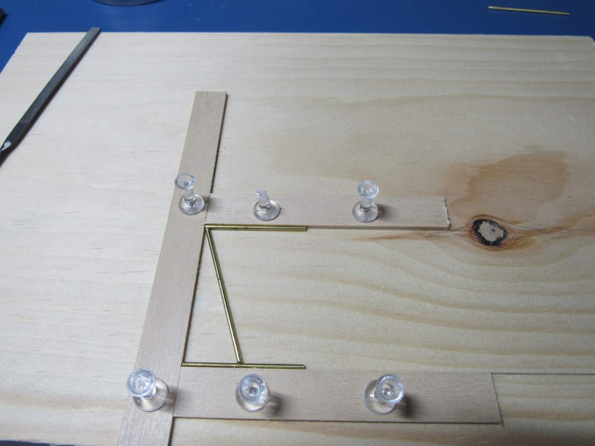
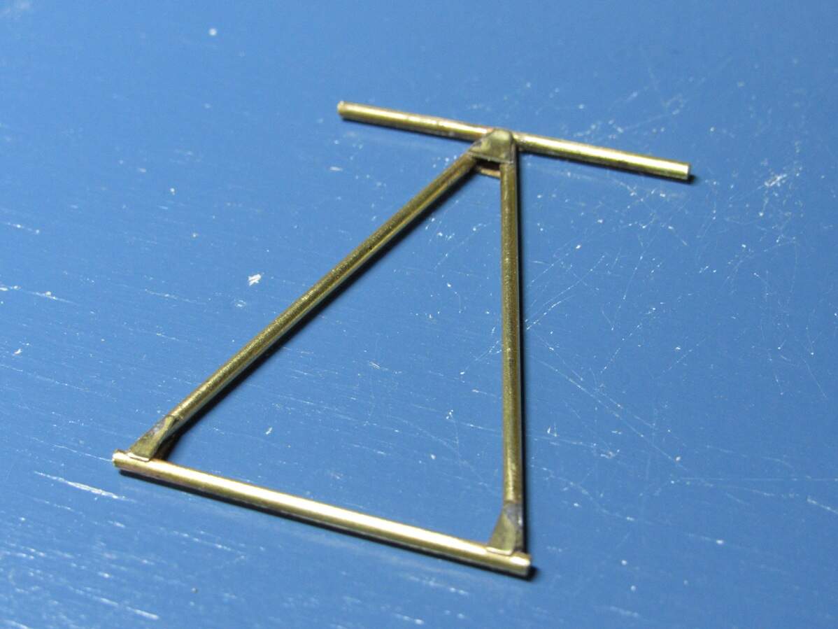
More progress tonight. The main cross member assembly connecting the two bridging units seemed like a daunting task. I had the idea of machining a jig for cutting the rods and assembling the structure. But once I had some rods cut to length I figured I could do this by hand.
Here’s my jig,
Just had to make sure it was square and that the opening width was correct.
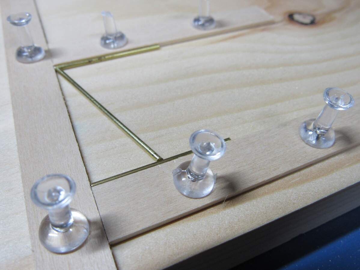
Here you can faintly see the two notches to mark the rough position for the point of the ‘V’. On the other end the design was to be ~1mm off the end, so I decided to eyeball it.
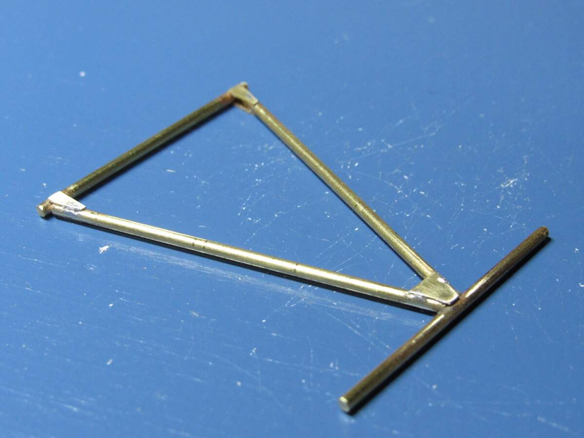
The angles on the rod were done with a file. Test fit, file, test fit, file, until everything fit into place.
Rods soldered together. Went much easier than the bridging units
After that it was adding some details. Each attachment point had a strengthening plate (I’m guessing on both sides). Added those and cleaned it up. Robin, I tried the chisels and it worked well, just a touch of sanding afterwards and it was all good.
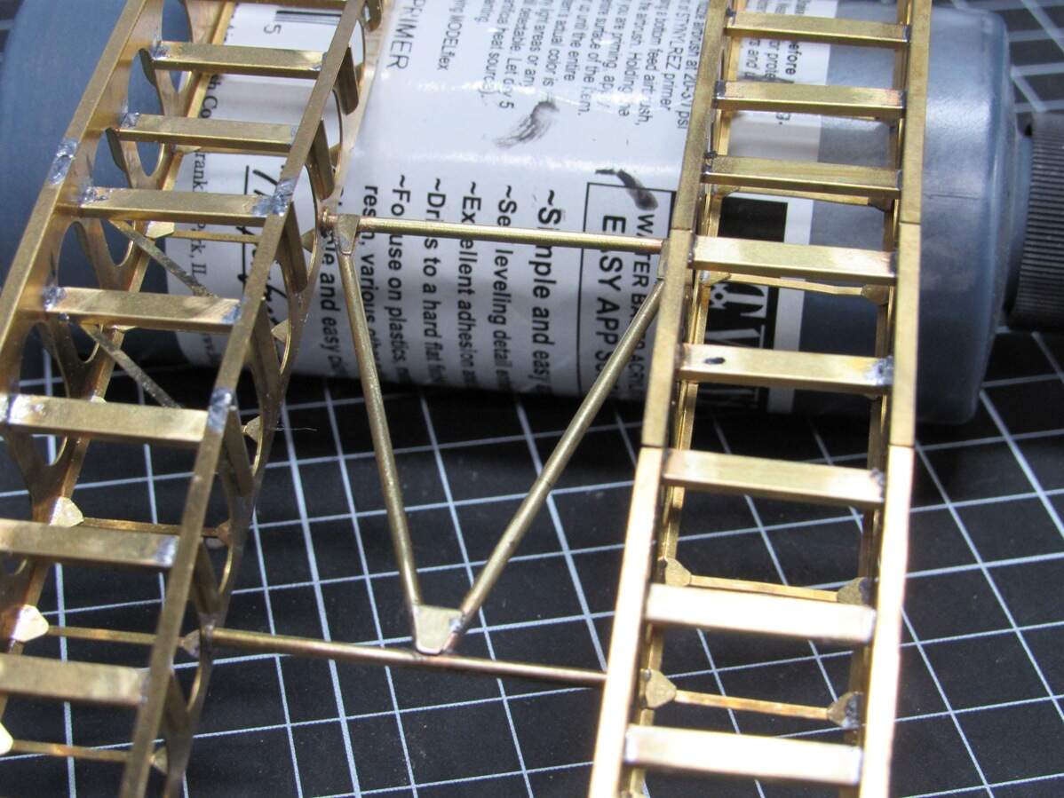
Being a little impulsive, I just had to superglue it in place and see how it looked,
Modeling this in the midst of deploying would make for an interesting build…
Stowed away for the night,
Following the suggestions in this thread I recently ordered a honeycomb soldering board and pen torch. Hopefully will be here by Saturday. Thanks for the help, they’ll certainly speed this project along.
I did catch a mistake in my bridging PE, nothing major (missed a cross rod between the two), I’ll make a note to include the needed PE in the next batch of parts. Think I may focus on getting the T-26 built up as far as I can, since I will need it for measurements for all the hull mounted parts.
Wow James this is amazing! I’m only just yesterday and today getting caught up with your progress; I’ve been slammed with work (a good thing) so I haven’t done much on my version. I hope to return to my efforts on the next couple of weeks.
Great job with using an iron to solder all that - a torch would definitely make life easier, or a resistance unit. I have a little torch that I got at Radio Shack, which worked quite nicely and had a small but very hot flame. I don’t even know if I could get gas canisters for it anymore. A word of caution - a Mapp gas plumbers torch would probably be overkill and might even ruin the parts - flame too big and too hot. But I love the look of all that metal! Mine won’t be nearly as nice looking unpainted lol. Anyway thanks for the updates and it really looks great!
Jimbo
Thanks Jimbo. I was thinking the same thing about the brass, I have a feeling that I’m not gonna want to paint this thing once I’m done building. Don’t worry about the Mapp gas though, not crazy enough to try that. Pen torch and soldering board should be coming in tomorrow, so maybe some more progress this weekend. Been focusing on the T-26 for now, hope to have that built up as far as I can soon.
Made a little progress last night. My soldering board, pen torch and brass tube came in yesterday. Still haven’t picked up fuel for the torch so haven’t had a chance to play with that, but I did cut some lengths of rod & tube to make the cable attachment to the front cross rail.
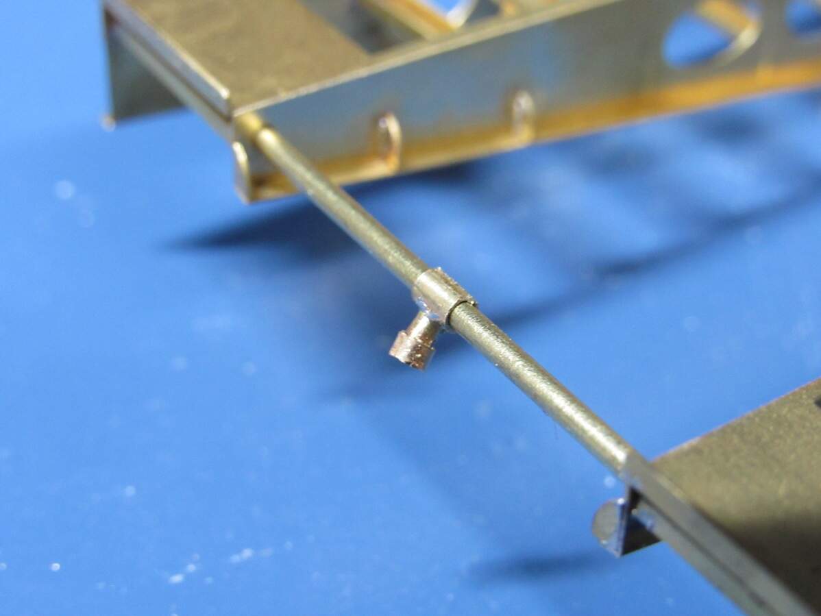
This area here is what I’m replicating,
In my design, for some reason, I made this a little piece of PE with an eyelet to glue the cable to. Don’t know what inspired that choice, and after looking over some references I thought I could scratch something better.
Just a piece of 2mm tube telescoped halfway over a piece of 1.5mm rod. Then soldered to another 2mm tube that’s free to spin around on that rail connecting the two bridge sections. Came out a little crooked… was a frustrating part so I think I may leave it.
Next up, gotta get butane for the torch and finish the ribbing along the second bridge section, and then I can join the sections together. Tomorrow’s gonna be rainy, good excuse to stay at the bench all day.
Some really fine brass work here. You guys make me sick. 
lol, thank you. Turns out it’s not all that hard, in fact it’s pretty enjoyable, and I like the look and sturdiness so much that I’m already working on another PE design, with ideas for a few more bouncing around in my head.
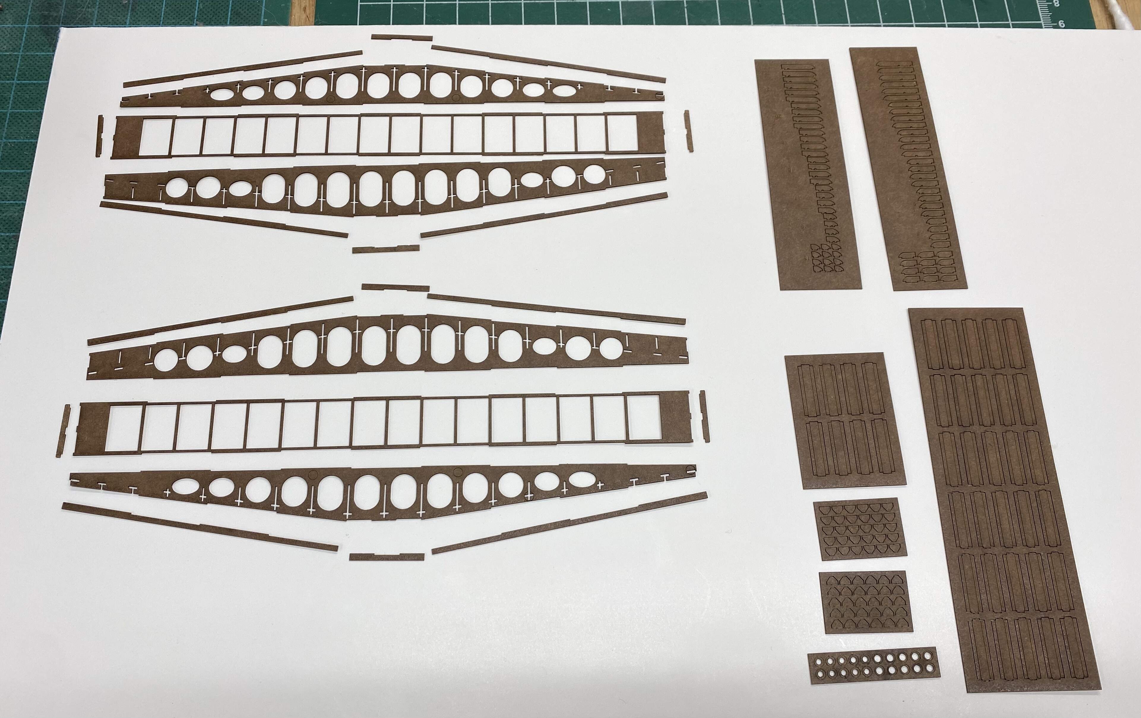
James and group:
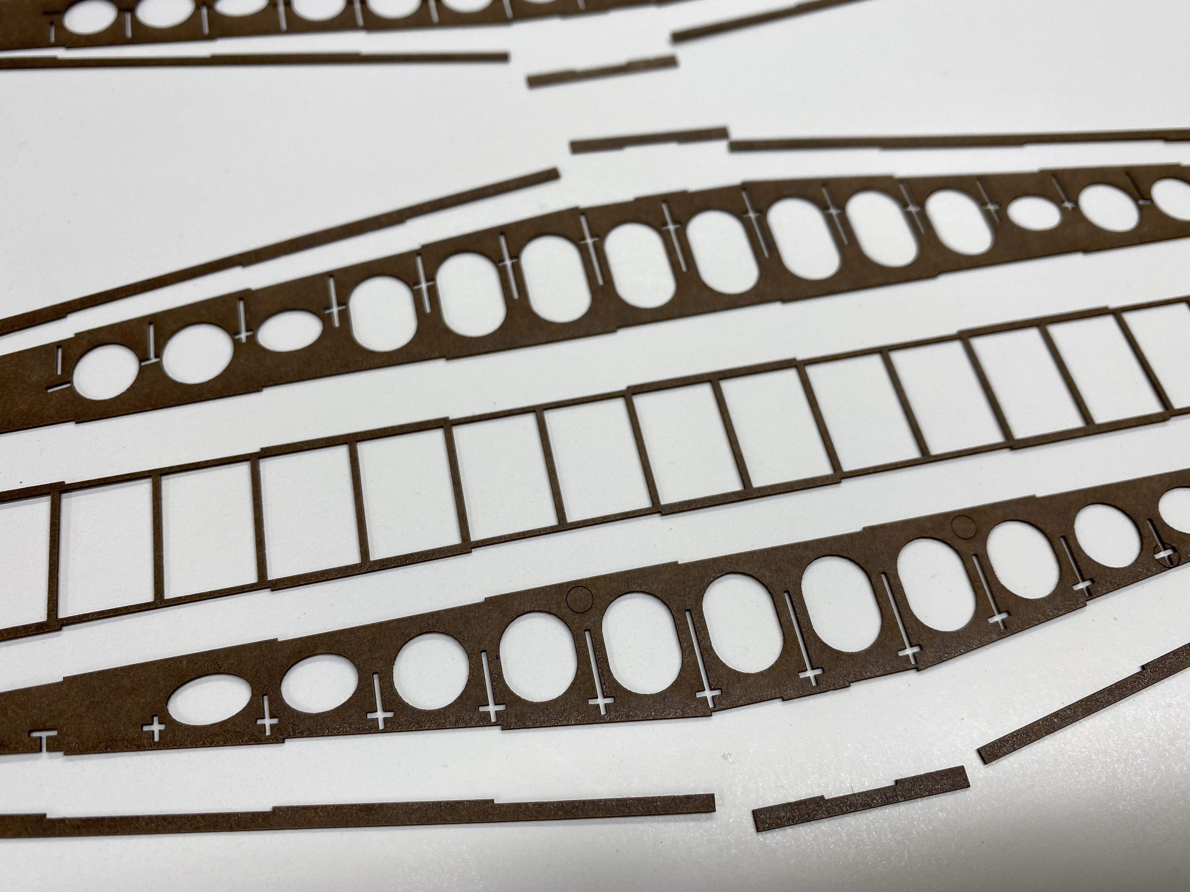
Here is my first round of laser- cut parts. I switched back to the “HDPFO” lens - the finest I have, which cuts a very fine kerf. I’m quite pleased with how the parts came out. There are a few groups of smaller parts I need to try and recut, but overall the entire set took 24 minutes to cut. About what I expected. Next step test assembly but I have some other commitments in my bench so it may be a few days.
Jimbo
I should point out that for my exercise here, I’ve re-drawn James’ files (with his permission of course) to accommodate a “tab-and-slot” style of approach. Remember - I’m using a resin-impregnated paper product (called ”Polybak” - it’s a cabinet-making backer liner that cuts nicely and has a very consistent thickness). So, in these photos you see cutouts for the “tabs” that don’t appear in James’ etched parts. A different approach, mine go together with a bottle of superglue instead of a soldering torch/iron 
Jimbo
Looking good. That is some extensive rework to suit laser cutting, but 24 minutes per sheet does beat out a month
Very interesting comparison of technologies here, now we would need also to see how it looks 3D printed…
You are both doing a great job!
Man I’ve gotta siddown and watch this. WOW!