ST-26 Bridgelayer, A T-26 Conversion Project

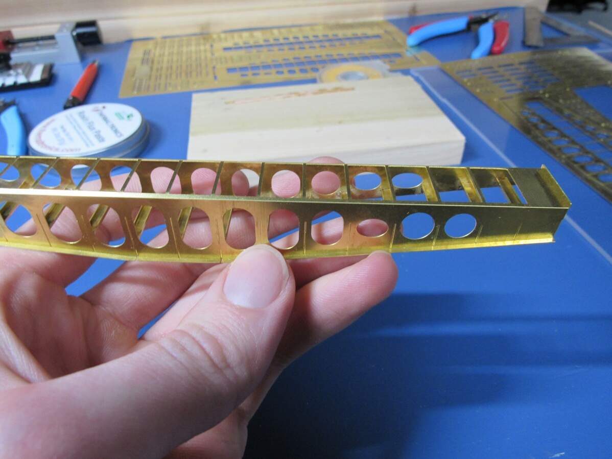
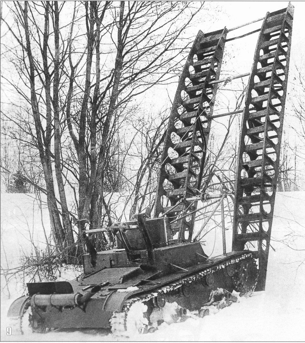
So that’s what I’ll be trying to build. The idea has been kicking around in my head for years now, and a long while back I even tried doing this with styrene. Cutting and sanding all those holes out got to me and it was scrapped. But now I’m back, with a new plan: Custom Photo-etch.

I had plans and pictures already collected, so those were ready to go, but before I could dive into design work, I wanted to have the donor kit on hand to properly scale the drawings I had found.

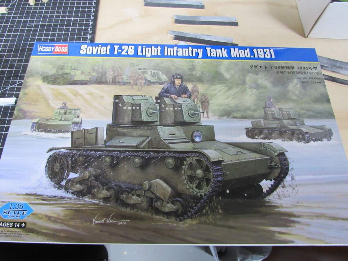
The donor kit. Posted a few weeks ago in the postman thread. I went ahead and built up the hull last weekend (no pictures, but I assure you it’s not all that exciting). Turns out my plans were scaled a couple mm’s off, so good thing I waited.

Custom PE was an option that hadn’t occurred to me years ago, but I figured there must be something out there, so with some searching the only company I found that caters to the hobbyist (or even mentions them) was PPD over in Scotland. They have some helpful guides on their site, so following those I dove into the design work.

Of course I needed to double my work load. I decided to rough out the dimensions in SketchUp, matching up with the plans, and making sure everything fit together. As I made or edited a piece, I’d jump over in AutoCAD and draw it out in there too. Can’t think of a better way to check my work so this will have to do for now.

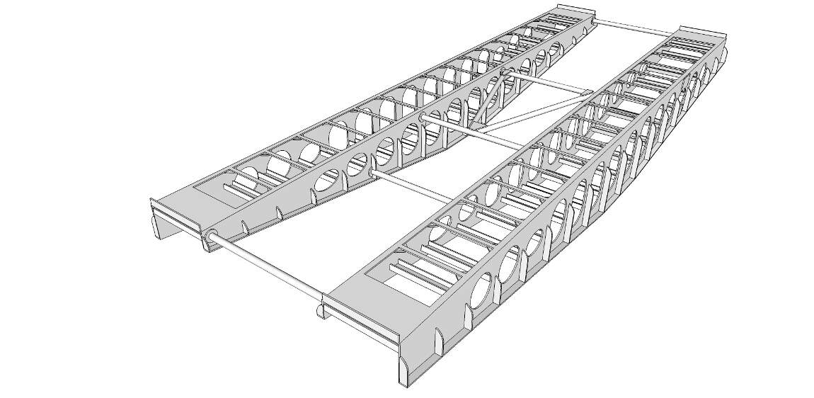
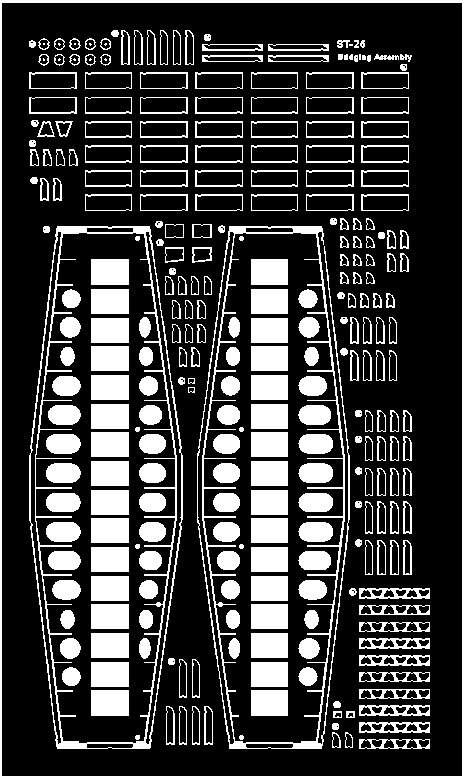
Here’s where I’m at in SketchUp,

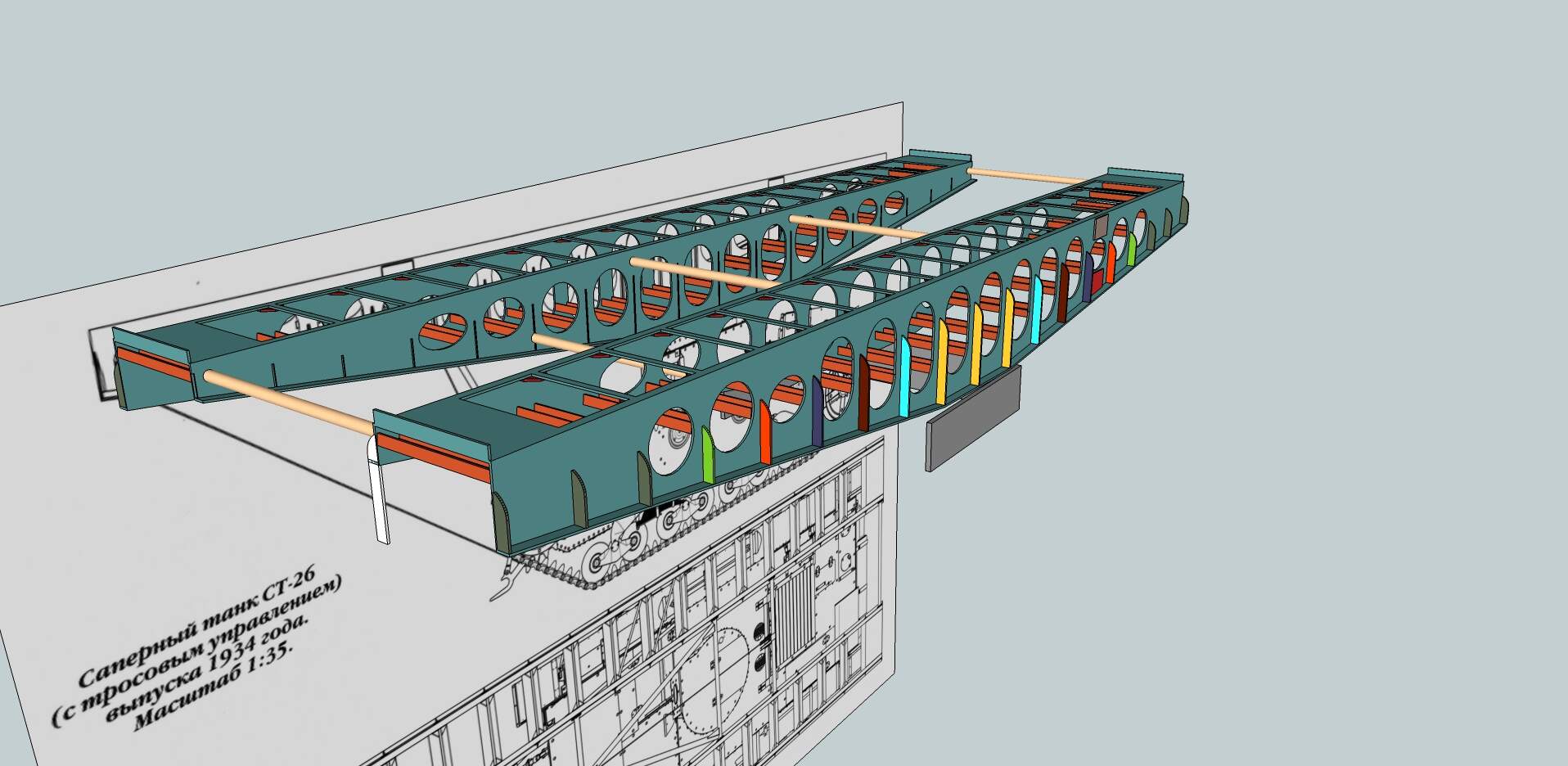
Don’t mind the rainbow colors, just making each part number a different color for ease of counting totals and for what goes where. An exciting way to spend Valentine’s day.

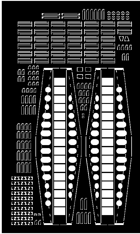
And here’s the translation in AutoCAD so far,

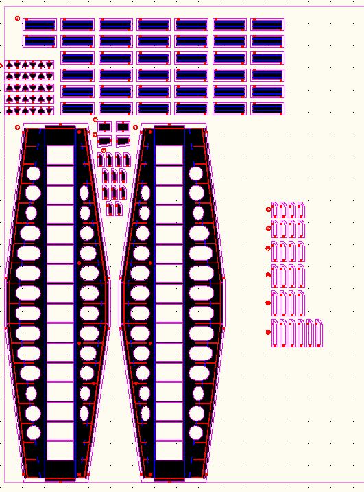
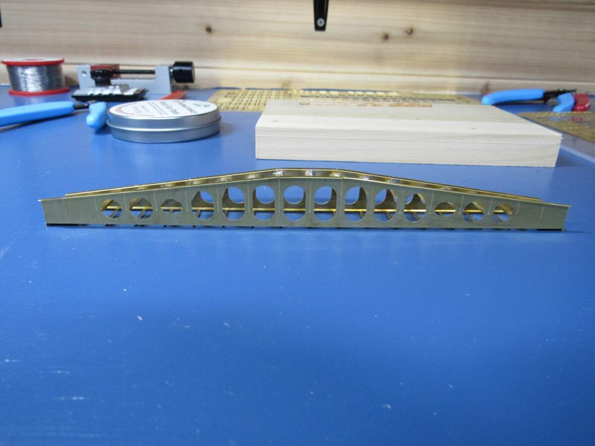
It’s gettin there. I’m thinking of doing this in two frets, one for the bridge itself, and the other for the hull mounted parts (this way I can order one sooner). Design wise, I’ve also been leaning more towards photos instead of taking the plans as gospel, so there may be some differences there. 100% historical accuracy won’t be happening here unfortunately, just not enough for me to go by, but I think I’m close.

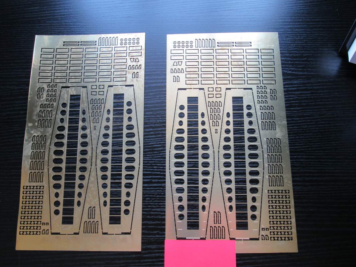
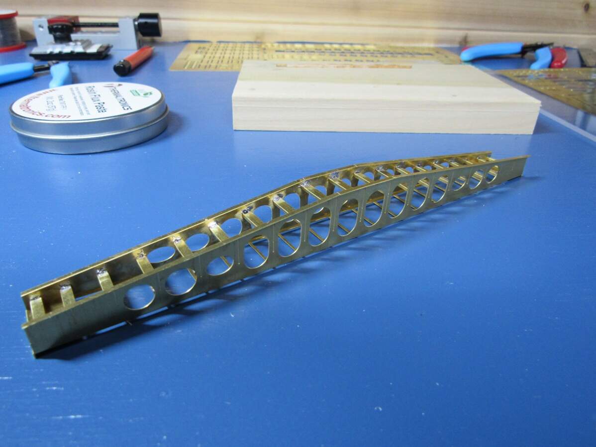
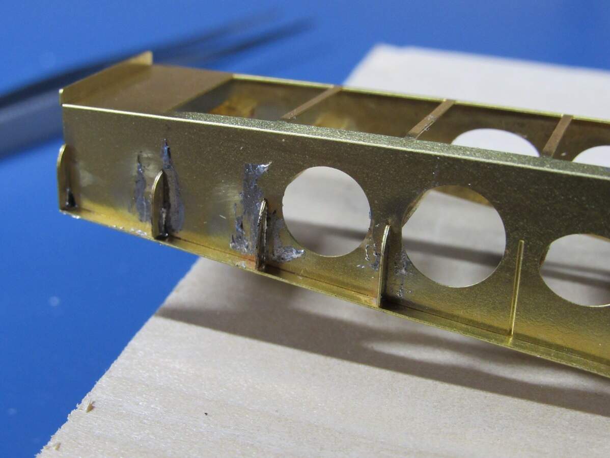
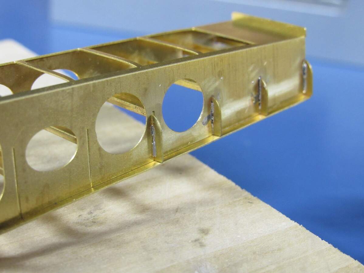
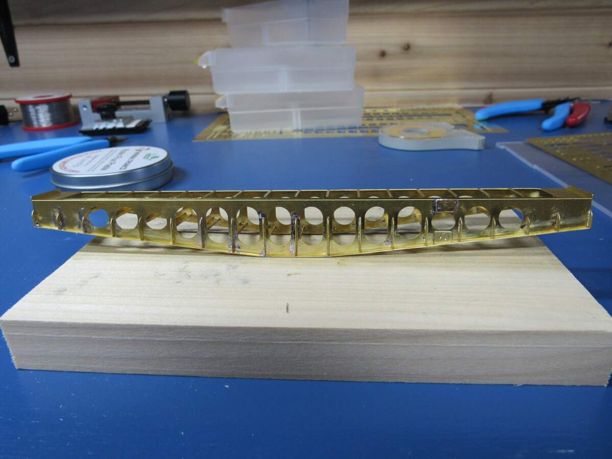
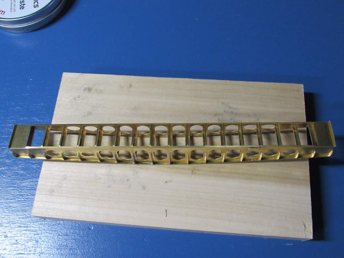
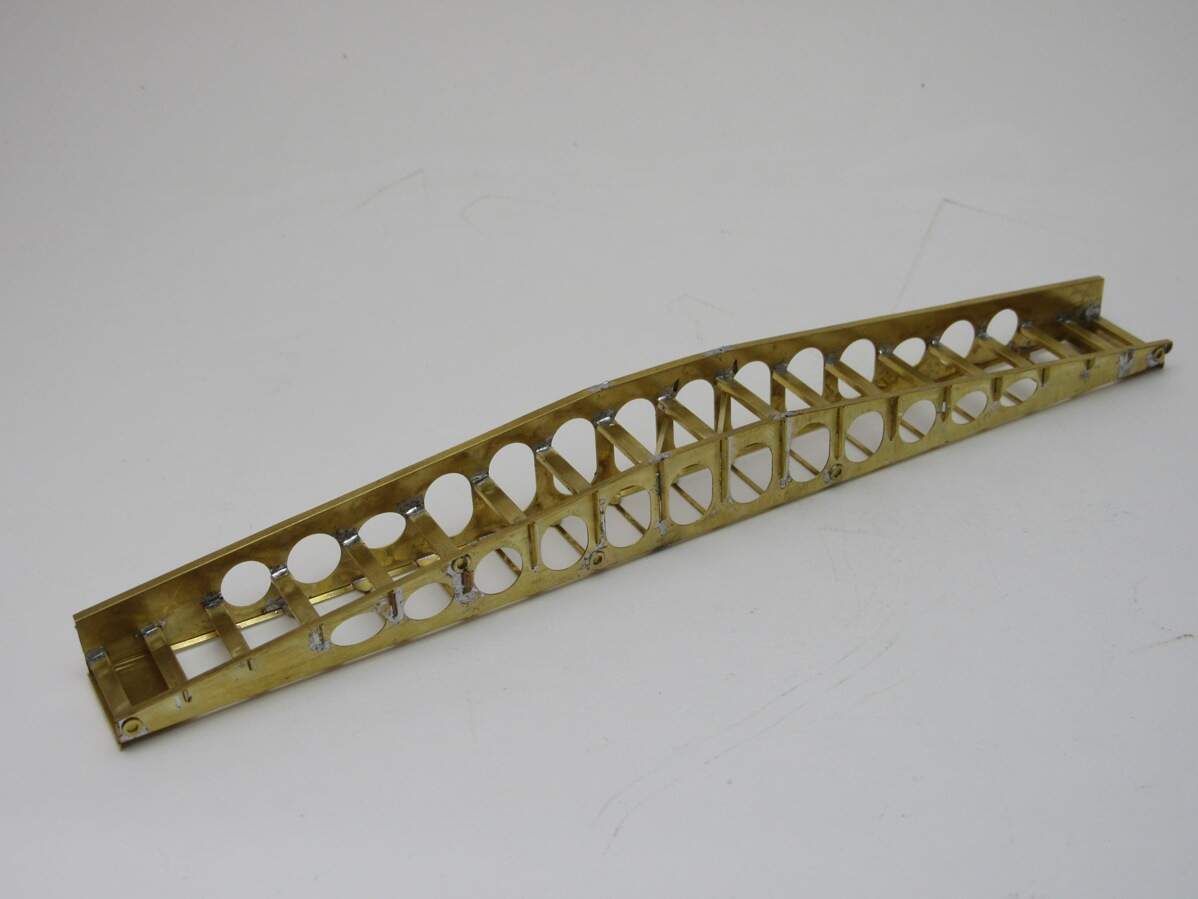
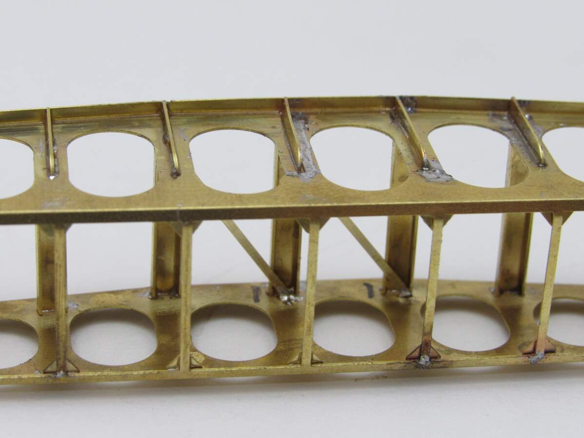
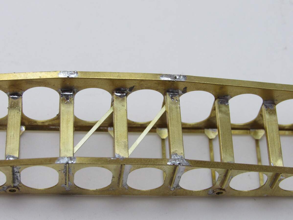
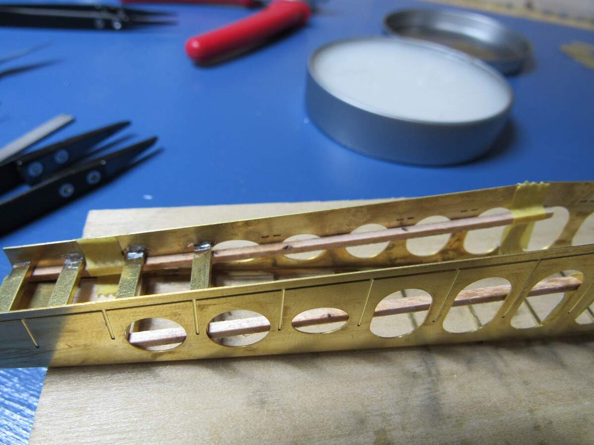
This is all a first for me. I’ve never designed PE before, never used PPD (and who knows what shipping will be like now), I also want to solder this together, which again, is something I’ve never done. There’ll be a lot of learning here. It will also be slow going, so this thread might be a bit premature, but I wanted to share it. Excited to get folding and soldering, hoping to have the bridge design complete and ordered by the end of the week.

Thanks for looking in.

9 Likes

This will look great! Cant wait to see more.

1 Like

PE may be a heavy set. I guess you can put weights in the hull.

1 Like

Have you considered laser-cut material? With proper design work (most of which you seem to have done already) I could cut this in minutes. Even if it’s just for proofing your CAD; I regularly use a cabinet-makers’ material that is a resin impregnated paper product, pretty stable, very consistent thickness, and super-glues perfectly. I’d be happy to give it a go, let me know if you’re interested. Seriously. I’ll be happy to share some examples tomorrow.

Jimbo

2 Likes

If you already have a 3D model, easiest way should be 3D printing… In any case, it looks great

2 Likes

I hadn’t thought of that… I do plan on using metal tracks though, as the kit provided individual plastic ones are a nightmare. Hopefully that will be enough.

Can laser cutting handle ‘half-etching’ or bend lines? Would require a bit of a redesign if not, and there would also be a loss of some locating marks.

I think the PE scales nicely in terms of thickness. I’m going with 0.3mm sheet, which is around 1cm or a bit less than half an inch in scale. I’ve been out of the 3d printing loop for a while, but can new printers handle walls that thin? Might end up pretty fragile too.

The laser can absolutely scribe in lines, but while the material in question can bend somewhat, it would be better off to separate the parts. The material I use super-glues together really well. I’ll share some photos of parts and assemblies made with it shortly.

Jimbo

Here are some quick snapshots of what my material can do, all representing sheet metal objects. By the way the material I have on hand is 0.5 mm or .020” thickness.

Above is a scale model of a bus shelter, that is about 3 cm square. Fabricated from laser cut sheets and features notches and tabs that, when filled with super glue and sanded, are indistinguishable.

Above is a scale model of a steel water wheel. The “bucket” parts are laser-scored and bent and then installed in the rings, located in place with tab-and-slot construction. Additional ring layers cover up the slot details.

Above is a rather poor photo of a scale framework on a grain elevator model. Same deal - laser cut material, tab-and-slot construction that is easily filled with super glue, sanded smooth and painted. Hope these help illustrate what I’m talking about. I don’t mean to hijack your thread so I’ll remove these once you get a chance to see them.

Jimbo

2 Likes

That’s pretty neat. You can leave the pics, I don’t mind. Laser cutters for modeling is something that hasn’t occurred to me, and I’m sure some other out there would benefit from seeing that. It would still require a bit of rework to the current design though, and I’m only about 3/4s done with the bridge design so far.

Well the bulk of the bridge design is done,

All that remains is one more detail part, then translating a few parts to the AutoCAD file, and finally arranging them for etching. I’ve also shared a copy of the AutoCAD drawing with @Jimbo which he’ll be modifying for his laser cutting approach. If this all works out I may just release the files when I’m done for anyone to get their own etch set, a sort of ‘open source’ modeling.

2 Likes

My grateful thanks to James for sharing his efforts with me. His work so far is exemplary; he shared his 2D CAD file with me and I have begun translating it to a laser-cuttable file as he indicated. This is a unique challenge and will take me a few more days of spare time to see if it can be done to a good degree of fidelity. There are some challenges but I’m confident. I love engineering vehicles in particular so this is quite a fun way for me to be involved in creating a different piece of kit.

Finally got the design for the bridging assembly done, here it is in front and back etching layouts,

AutoCAD is something I use very rarely, so it was learning as I go, then going back and redo some work, over and over as I got the hang of things. For example the ‘hatching’ (filling in solid blocks of color) was taking forever and giving odd results. Turns out some of the geometry for the lightening holes had 1000+ copies of the same thing stacked on top of each other… God knows how I pulled that one off.

But it’s done now, ready to send it out for etching later today. Now to see how long it’ll take to get over here. In the meantime I’m thinking of investing in a soldering station, currently only have a plug in iron with a horribly corroded tip.

3 Likes

As some of you may have seen in the “What the Postman Brought Today” thread, PE for the bridging units arrived today.

They were packaged nicely, wrapped up and taped to a firm backing board to prevent any bending. Looking them over I haven’t noticed any issues. I also ordered two sets on the possibility of me really screwing something up. Total cost including shipping was ~80$. Doing only one set would only save like 12 bucks, so I might as well…

Couldn’t help myself and had to start building. I bought a proper soldering station about a month ago for this project. I mess around with electronics and have sweat pipes before so soldering isn’t new to me, but this is the first time that I am soldering PE. No surprise that there is a bit of a learning curve, but I’m getting the hang of it despite a few ugly joints.

But first I had to cut and clean some parts. I started with the frame of one of the bridging units. I decided to bend that in a 12" brake I have as the part is pretty big. Next were the rungs, 19 of them bent to shape. Turns out they were pretty fiddly to get in there and I had to get creative. Basically I had to tape down a small strip of wood so I could rest the rungs on that to keep them from moving. I’ll take some picks on the next one to give you a better idea.

So here’s where I’m at,

Tomorrow is gonna be nice and rainy, perfect excuse to stay in and work on this. Gonna try and finish up this bridging section.

12 Likes

Well worth the 3D design effort and the wait, James!

Cheers,
Angel

2 Likes

Thanks Angel. Spent hours at the bench today cutting, cleaning and soldering parts. Focused on getting the vertical supports on the sides in place, plus the other details on the sides of the bridging unit. Tedious work as most of the supports are different sizes so care needs to be taken to not mix them up.

I leaned heavily on a small benchtop vice for cleaning up small parts. I’ve had a hand held one for years, but it requires two hands just to hold and open/close the jaws which makes it hard to get small parts lined up in there.

This can be opened and closed with one hand while the other works on positioning the part. Much easier.

So with parts cleaned up and sorted I got to soldering. First few joints were a bit rough. Went a little flux happy and solder spread all over,

But I started getting the hang of it,

I have some solder wick, so I’ll give it a shot and see if I can clean up some of the mess.

But anyway, I managed to get the supports done.
Looking at the outer side, which is taller than the inner

Looking down on it in the carrying position. It’s carried upside down

Laying down in the deployed position

That’s all for today. There are a few detail parts to add and this half will be done, well, besides cleanup. Not sure how this week is looking for bench time, but I hope to get to it soon. Also need to come up with a jig for the rails between each bridging unit… One step at a time.

6 Likes

Very nice progress. A single hand operable bench vise is a good idea.

1 Like

It is a good idea, can’t say it was mine though. Think I saw a picture of someone’s bench with one, and realized I needed one. Been very helpful so far

Finished the first bridging unit last night, quite a few detail parts to add.

Tried cleaning up some of the solder with some desoldering braid I had on hand, but no luck. There’s some filing and sanding ahead for me. On to the next half, hopefully it’ll be cleaner this time around.

1 Like

I’ve made a start on the 2nd bridge section. In order to get the treads in the right spot I tape on a strip of wood just below those snake bite placement marks,

My first thought was that I could lay this side ways and press down to keep the treads in place while soldering. Turns out that was too tricky and taping on some wood cleats was much easier.

I’ve learned that to get the best joint you heat from the backside until the solder flows. Unfortunately I can’t always get that to work. I have an adjustable temp iron maxed out at 850F, and I can hold the iron in place for 3-4 minutes and get nothing… but sometimes it works within 30 seconds. A little frustrating, so when you see those ugly joints it means I got annoyed and went in from the front like a caveman.

Still plenty to do, and I’m coming up with ideas for a jig for the rod framing that connects the two units together.

5 Likes

There is a difference between temperature and being able to deliver lots of it.
You need to look at the Wattage of the soldering iron.
There is a lot of metal in those parts that will steal your heat and if the soldering iron can’t pump heat into that joint faster than the sheets of metal can dissipate it you won’t be soldering any joints.
I would be looking at 80 to 100 Watt irons for this type of job

One possible improvement could be to pre-tin the joints. Heat each piece separately and add a small amount of tin. When you join the pieces and heat them again the tin will already be there and
in the right amount. The handling also becomes easier since you don’t need to get 4 things lined up at the same time (two pieces, tin and iron).
If the “snake bites” need to line up with tabs on the treads you will need to get the pre-tinning tin out of the slots.

2 Likes

Another thing: Small/Tiny chisels can be used to remove excess tin …

2 Likes