Lol it is indeed, although it took me, what, TWO months of spare time to get to this point! I do still think the photoetch is the best solution, but this is a fun exercise for sure, and my grateful thanks for you being so receptive to allowing me use of your file, James.
1 Like
Was gonna paint the house today… but I put in a full day yesterday and don’t feel like getting any more sunburn, so I went down to the workbench instead. Finally picked up a can of butane for the torch and gave it a go. Complete game changer, within a couple seconds the solder is flowing as opposed to the couple minutes were it only might flow with the iron. Once I saw how fast and clean it was going I decided to finish up the 2nd unit and connect the two together.
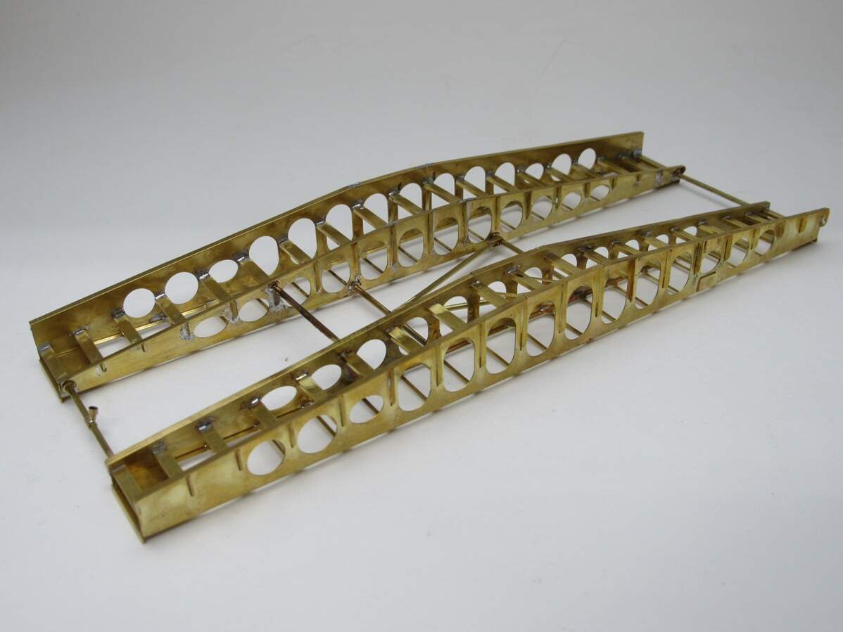
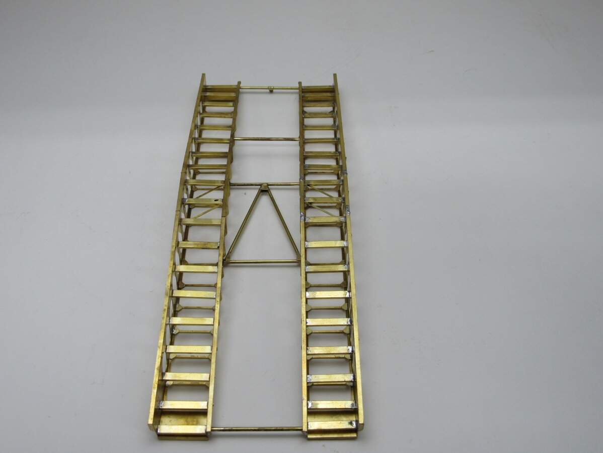
That’s the good side. Getting all the rods to line up was a pain, but I got it done. I learned that the torch isn’t the end all be all tool. There was some collateral damage when soldering the connecting rods, so I switched to the iron which worked just fine in those tight spaces.
I did discover one critical flaw…
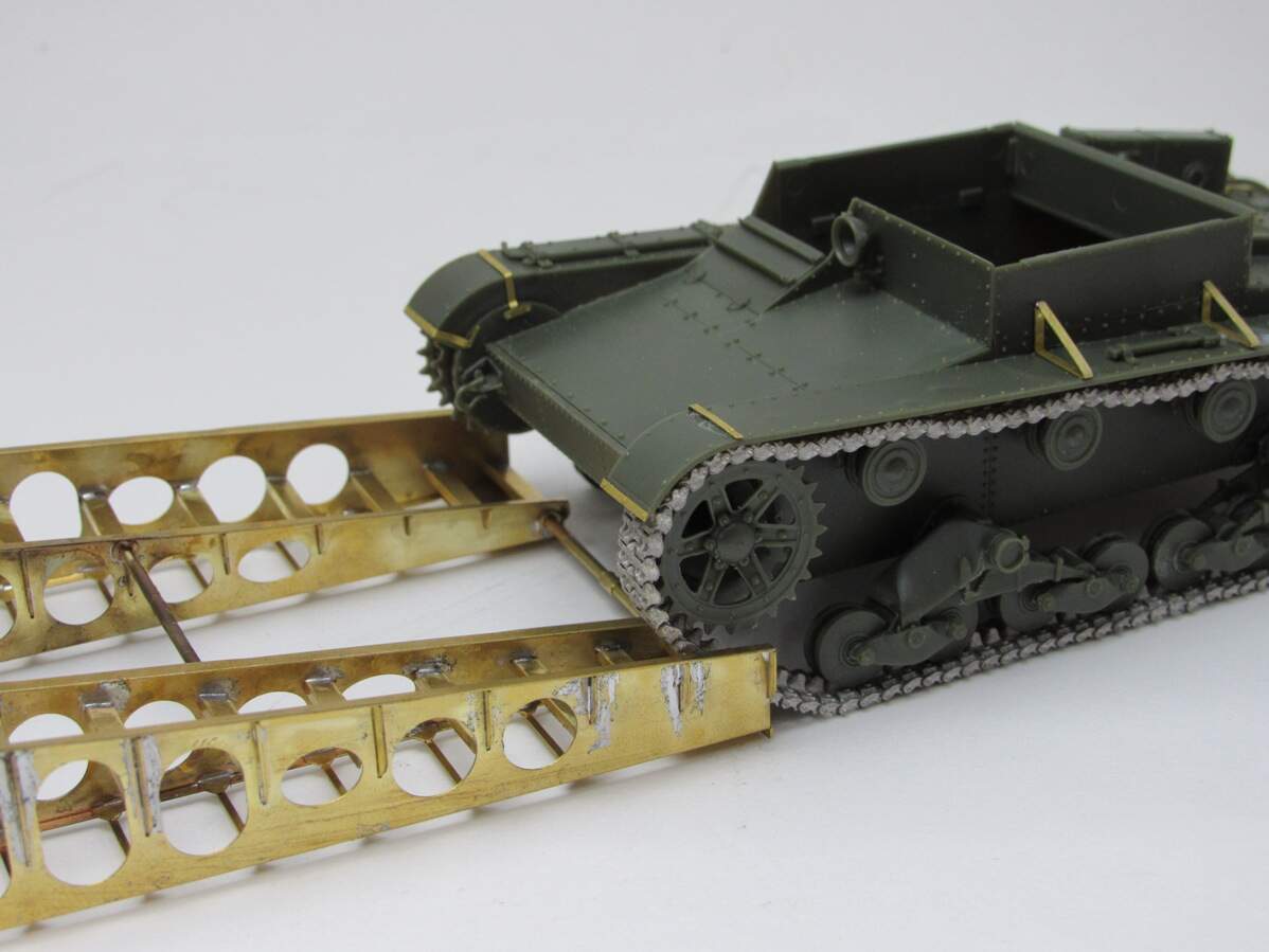
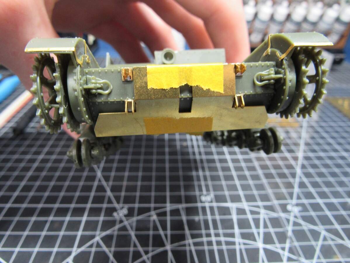
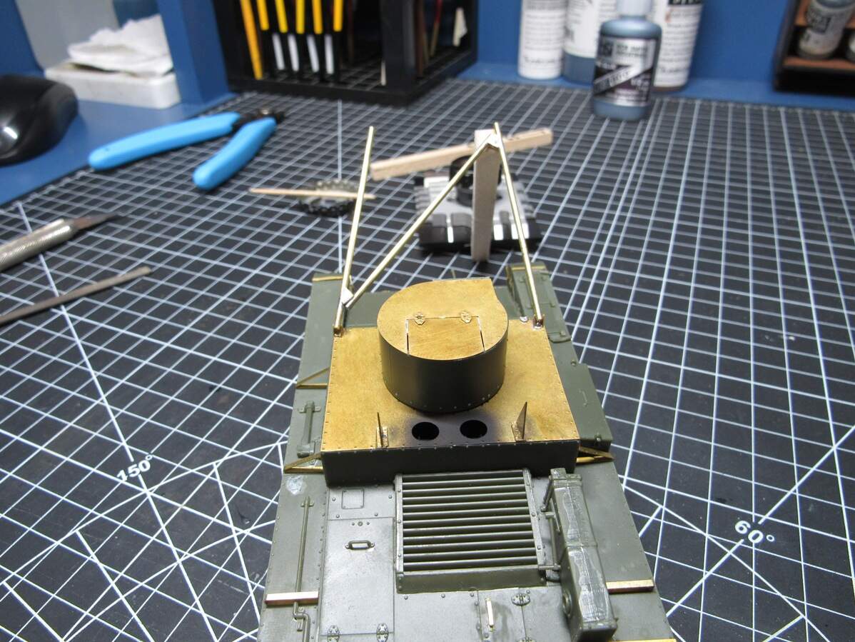
The tank doesn’t fit, lol. I’ll go back to the design and add another 5mm to the rod lengths, but for this bridge, really don’t want to tear them out and rebuild. It’s going to stay as is. This is why I ordered a second fret. I planned on modeling this is the middle of deploying, or stowed anyway, so it’s not a big deal, it’s close enough it would be hard to tell looking at it from above. If I want one in use I can always build the spare.
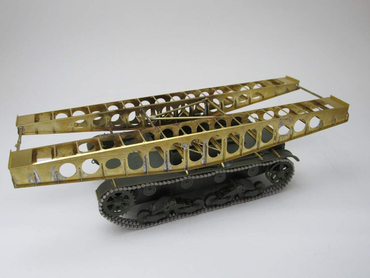
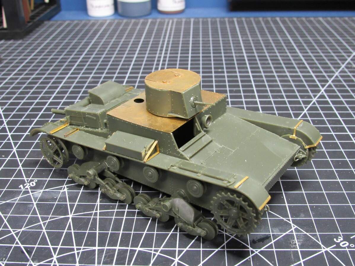
And there it is resting on the base kit to give a sense of scale. Just have the other run of track to do and the T-26 will be as far along as I can go. I’ve made a start on the rest of the PE design, about half way along with the 3D work. Would like to wrap that up and have it sent out within the next couple weeks.
I’ve been thinking more about marketing this when it’s complete, but it would only be worth it for me if ~10 or more people were interested. Couldn’t tell you cost, but would likely be more than the base kit. Show of hands, who’d be interested?
9 Likes
Soldering:
Big heat for big objects
Small heat for small objects
It gets tricky when small objects need to be soldered to big parts
Slogging on through the CAD work
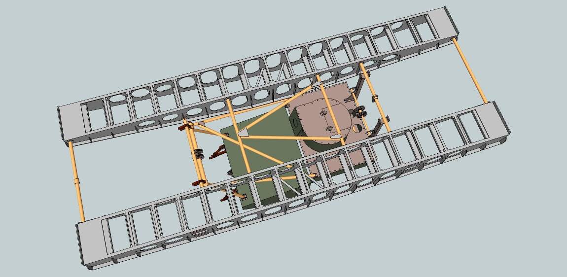
It’s been a drag but I’m very close to done. Most 3D parts have been transferred to AutoCAD as well. A few loose ends, and then laying out everything for etching. I have some PE construction jigs in mind that I may add as well.
Turns out there was another modification to the base kit that I didn’t notice until recently. I’ll have to chop the turret down. Luckily I get two tries at it. Designed some PE to restore the detail on the top too.
6 Likes
"Turns out there was another modification to the base kit that I didn’t notice until recently. I’ll have to chop the turret down. Luckily I get two tries at it. Designed some PE to restore the detail on the top too."
And that right there is what happens. lololol. One mod affects something which affects something else which…You know the deal. This is lookin’ really good so far bud.
2 Likes
Thank you. I think that was the last of the ripple effects, now just to design a couple more parts and send this off for etching. Hopefully I’ll get that done this week, then it’s waiting another month…
1 Like
Alright, I sat down and powered through the majority of CAD work. Gotta say, I’m growing to hate AutoCAD more and more. The hatching tool is so god awful I don’t know how this is considered professional software. When I can get different results by doing the same exact thing twice, that’s how you know it’s good.
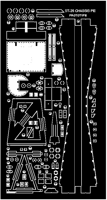
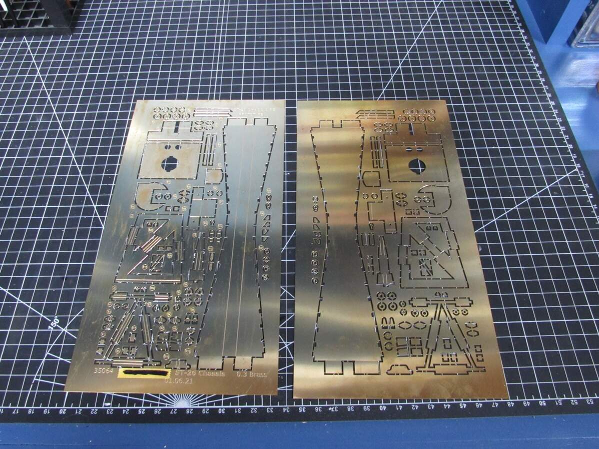
Anyway, that’s a picture of the front etch. I’m gonna have to comb through all of this to make sure the hatching is correct. Then do the backside, no rush though, maybe I’ll get this out early by Monday
2 Likes
2nd PE fret came in today, much earlier than expected which was nice. I haven’t had a lot of bench time lately, but I couldn’t help myself and had to play around with it.
PE frets front and back,
Detail shot of the new hull and turret tops,

Decided to start on the turret as that can be its own little sub assembly. Was a little apprehensive as I had to chop it down, but it turned out to be easier than expected. Using a piece of tape as a cutting guide I went at it with a hobby saw.

A couple minutes later and I’m left with this,
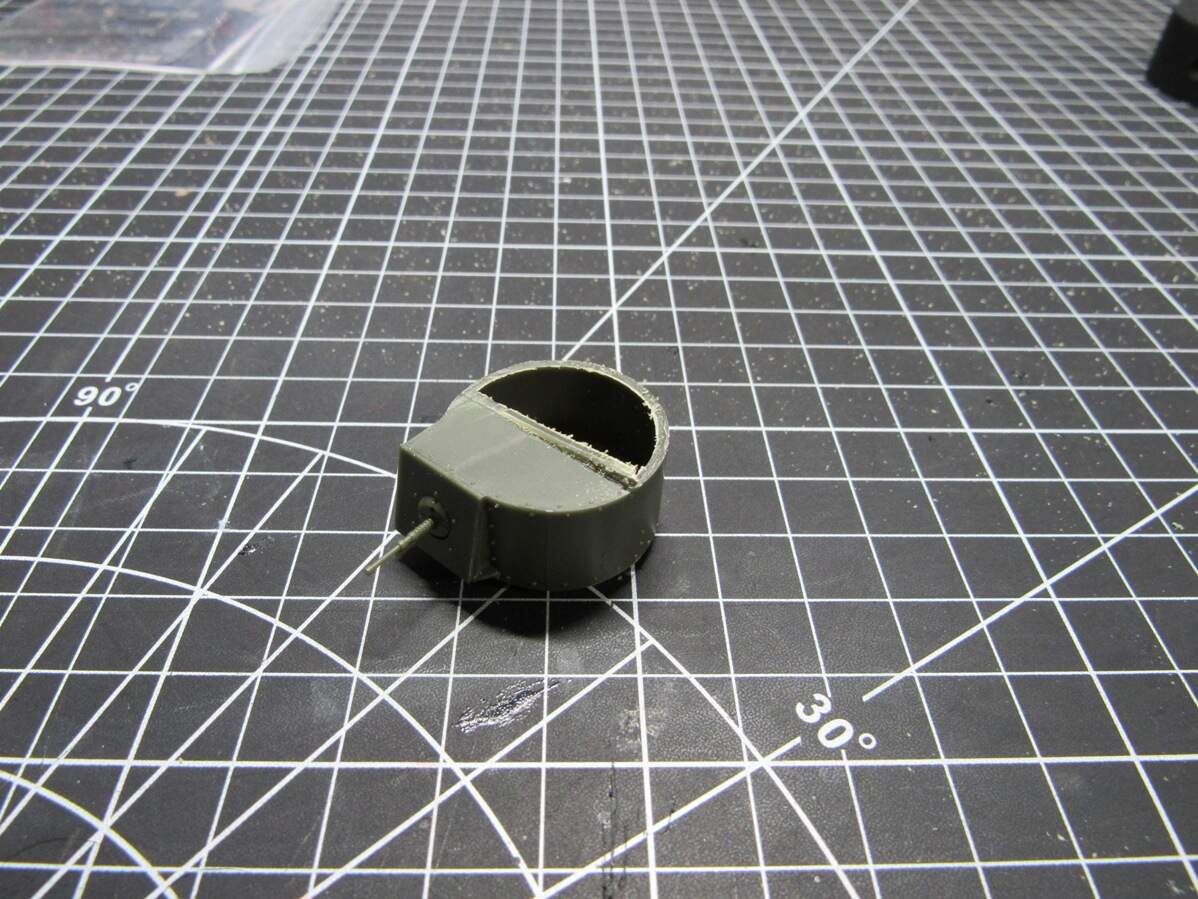
A touch of filing and sanding got it looking presentable,
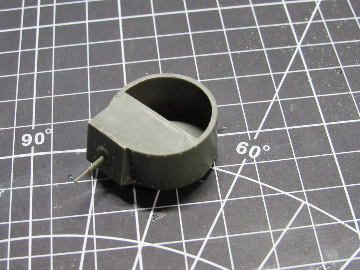
Now the moment of truth. Did I measure correctly? Will the new PE part fit?
Well, I kinda got it right. Major diameter was fine, but I was about 1-2mm proud on flat side. Had to trim and file it down, lost some rivet detail in the process, but I’ll figure a way to repair it. Maybe little drops of super glue. Besides that little hiccup, the rest of the turret went together fine.
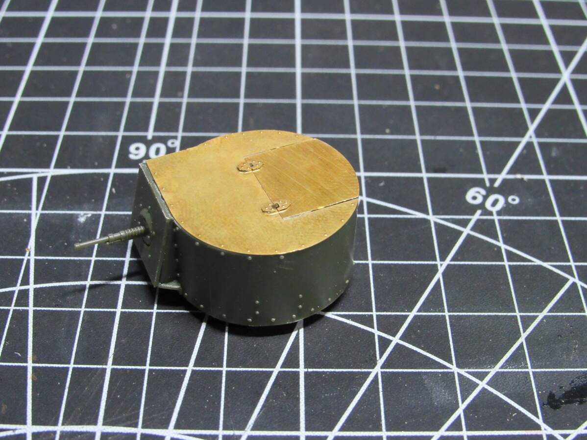
Also caught another mistake, think I shorted myself on hinge parts. Not a big deal, this is why I ordered 2.
Turret done I had to mount it to the hull and test the fit of replacement top hull plate. This fit without issue.

That’s all for tonight. Not sure how much I’ll get done this weekend, house painting and yardwork are taking precedence. There’s also some various brass rod sizes I need which should be coming in next week. Happy with this build so far, looking forward to getting more bench time with it.
8 Likes
Wow That is a game changer . That PE looks amazing.
1 Like
Wow!!! What a difference some PE makes. You know how it is in the world of modification, you mod one thing and you have the ripple effect going on with adjustments and more mods. You’re doing a great job with this beauty!!!
1 Like
Thanks guys. Gonna be a hot one tomorrow, may just stay inside at the bench where it’s safe and build away
1 Like
Its always safer at the bench…lol
1 Like
Fortunately it’s not that hot here today. This has been one helluva start this year weatherwise though. Good thinkin’ on the benchtime. 
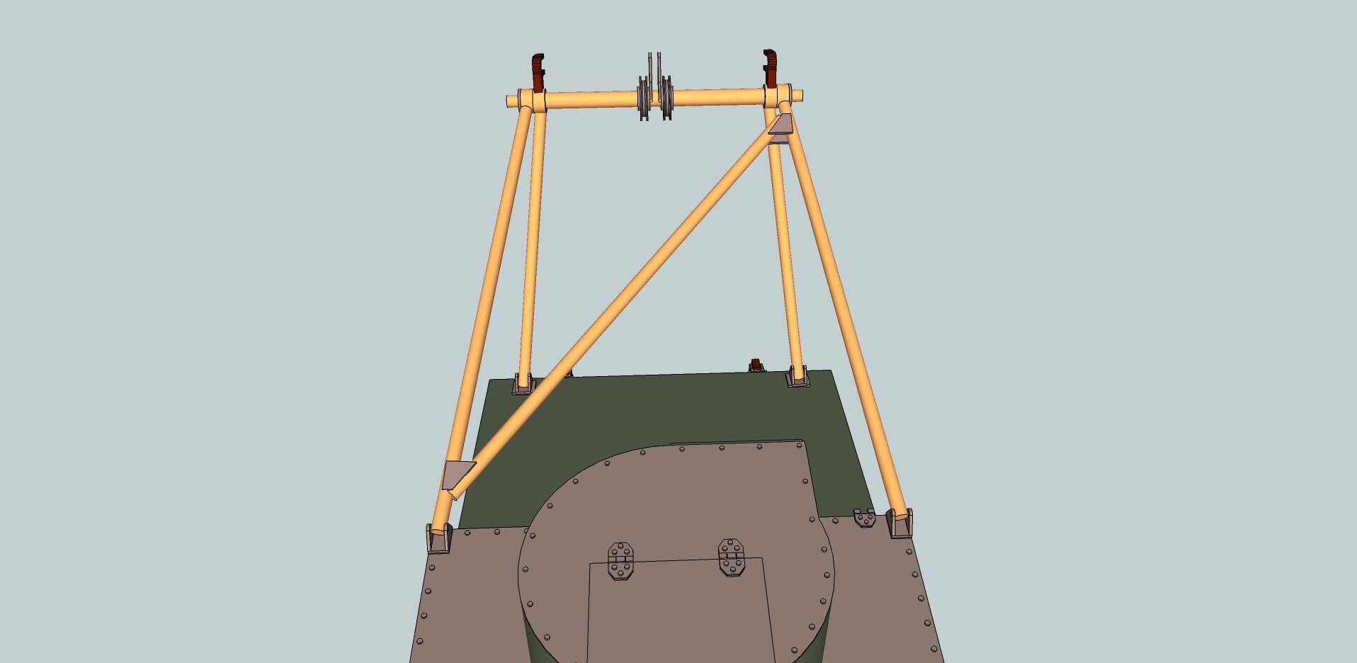
Couldn’t keep my promise, some plants came in the mail today so I had to get them in the ground. A little sunburnt, but I got some modeling done before and after. This morning I started on the lower hull mounts that hold the arms that stop the bridge on the way down. When designing I figured their location would be nice to get right, so I designed a placement jig to go with it,
And with the jig removed all looks good,
I’ll have to get started on scratchbuilding those arms. More ‘traditional’ methods of scratching with sheet plastic isn’t my strong suit, but I want to try my hand at it. Anyway, I carried on with soldering what I could. I made both rear support brackets, they’re mounted on the chassis behind the turret and hold the bridging unit during transport.
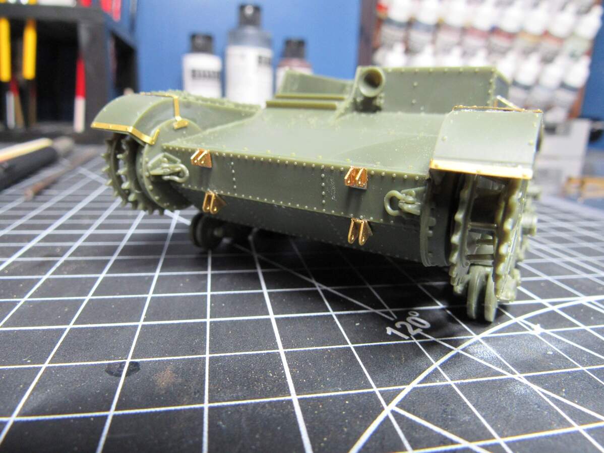
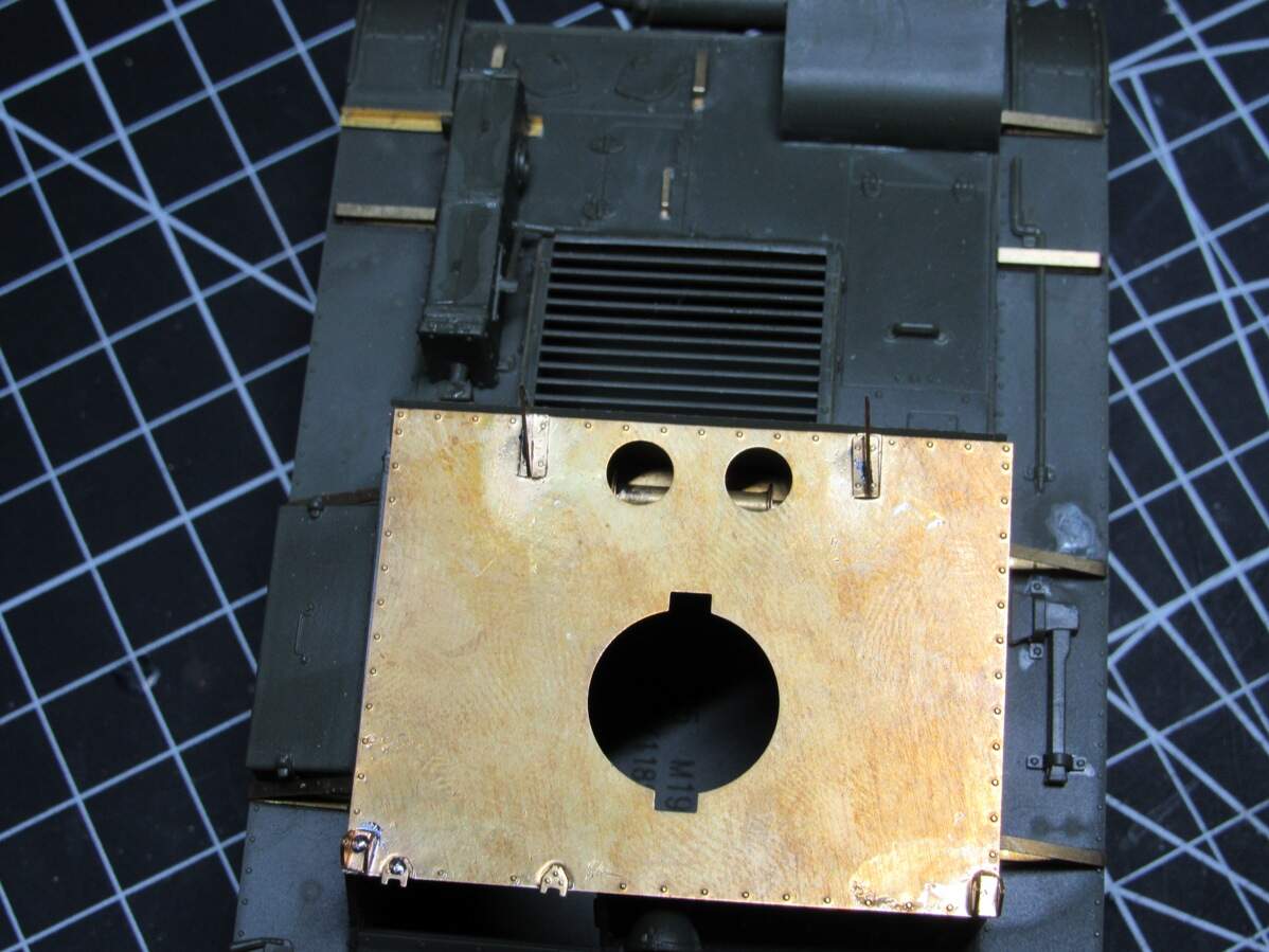
Those were tricky to solder in place, but in the end I got something passable. Then I detailed the upper hull piece with hinges and mounts,

Early on I realized those two cable holes towards the rear of the top plate would have to be filled with something. Lacking any references I decided on a simple spool that gets boxed out with another piece of PE.

Should provide enough detail when looking down on the model,
That’s all for now. In a couple days I’ll have all the brass rod & tube needed to complete the build, then hopefully it’s smooth sailing. Still got a lot to do.
6 Likes
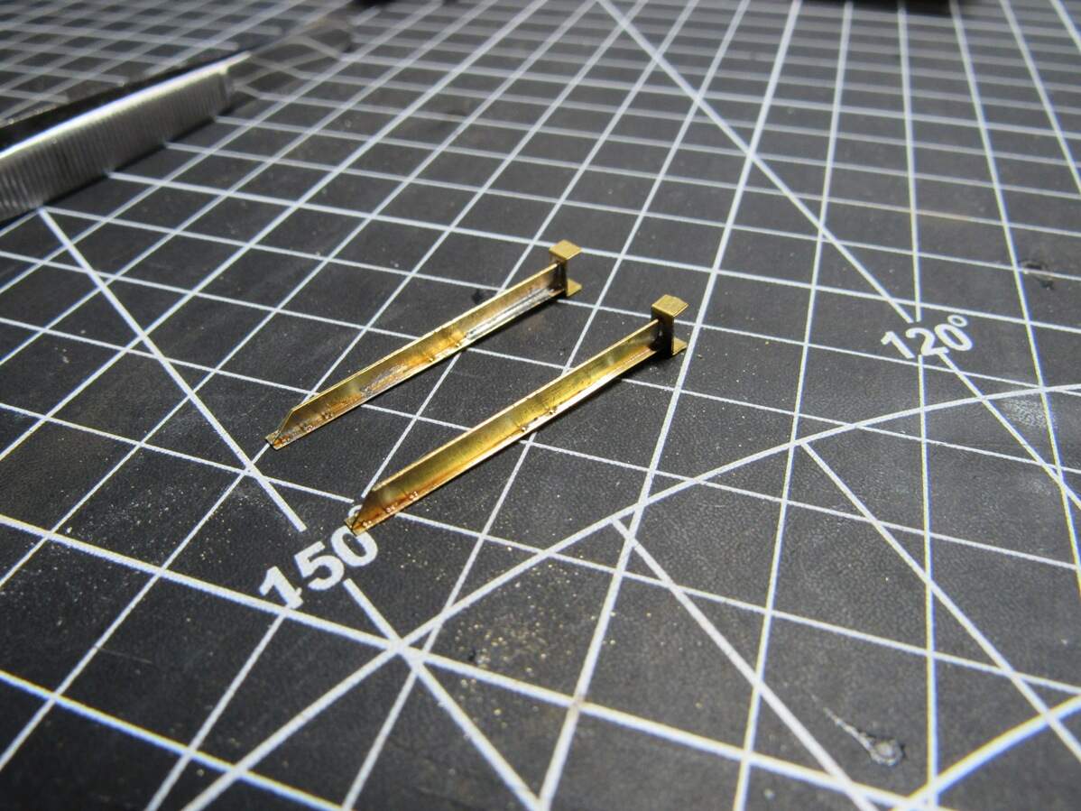
Small update tonight. Managed to get some brass rod work done for the chassis mounted bridge support structures. I tackled some of the assembly that connects to the top of the hull.
I made a jig with the PE to help with alignment, with some rods cut to length and placed inside. Folding the jig was actually a little tricky, but since it’s not part of the model I had no problem ‘motivating’ the hard to reach areas with some pliers.
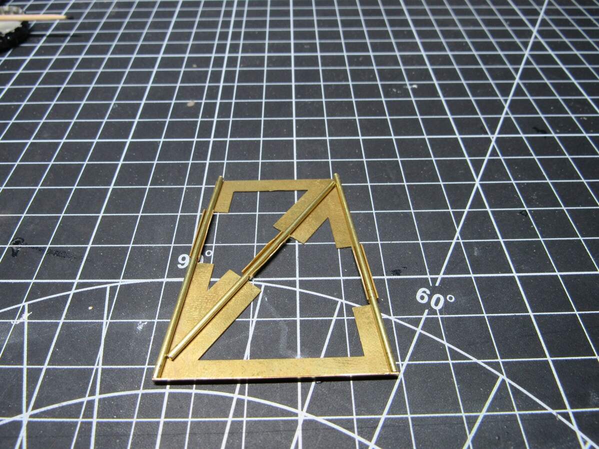
Now the jig does make alignment easier, but I was having trouble soldering everything together. Took some re-work and swearing but I got it done,
I primed the winch area, so the top hull plate was ready to be glued down, which I started. It’ll take a couple sessions of super glue to get it flat, then maybe a bit of filler. But naturally, I had to see how the support assembly looked in place, which took a little improvising

It’s getting there
5 Likes
That looks amazing
Jig work.
Draw the pattern on a flat piece of wood.
Tie down the pipe sections using copper wire through holes in the wood, use pins or small nails if needed to get total positional control.
What Robin said … Cork board works good for jigs .
Anything that is solid enough and can take the soldering heat.
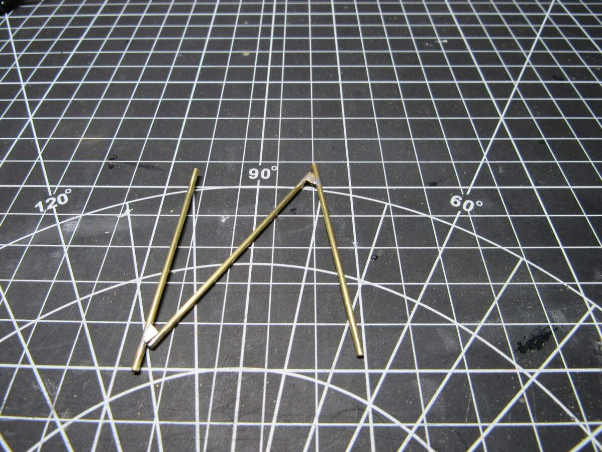
Guess I should elaborate, the jig worked fine. Soldering the webbing on the top side went without issue, it’s when I went to do the other side that I’d end up re-flowing the existing solder and the rod would move on me. I think I could avoid this by actually soldering the rods themselves together with a nice angle filled to fit on the diagonal rod. Would be a more substantial joint, harder to re-flow, and overall stronger than relying on just the webbing to hold it together. Learning lots of little things with this.
I still have the idea of marketing this when done, so that’s also why I’m experimenting with jigs. It’s a complex build, and anything that could help the end user I assume would be appreciated.
Edit: Oh yea, my remaining brass tubes and rods came in the mail today. Nothing to hold me back now, hope to make a ton more progress this weekend.
1 Like