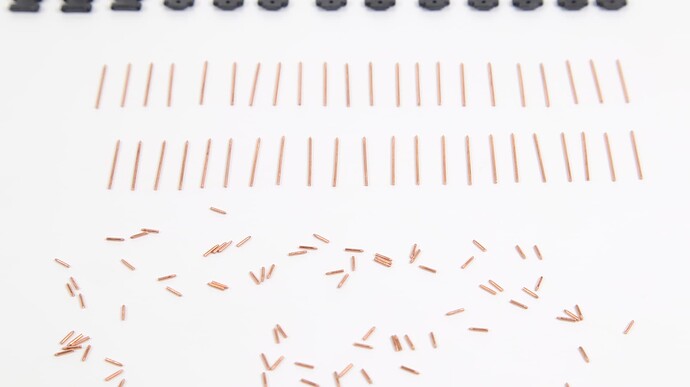
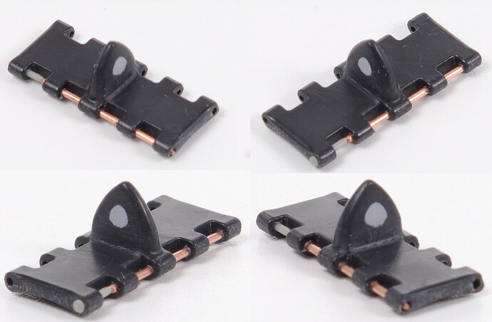
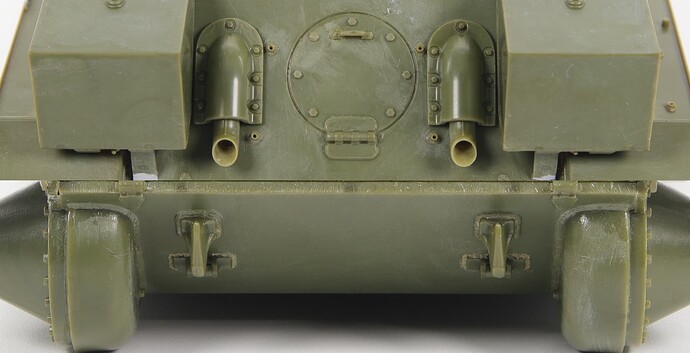
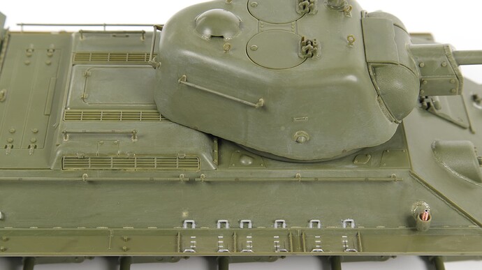
So, friends, I’m finishing up the long-term construction. And I want to do this with your participation. I propose the following construction format:
-
I voice the upcoming stage of work.
-
Together we discuss all sorts of issues and details of this stage and make a decision.
-
I am trying to implement this decision.
-
I post a photo of the result.
-
Together we analyze the work done.
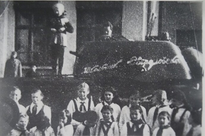
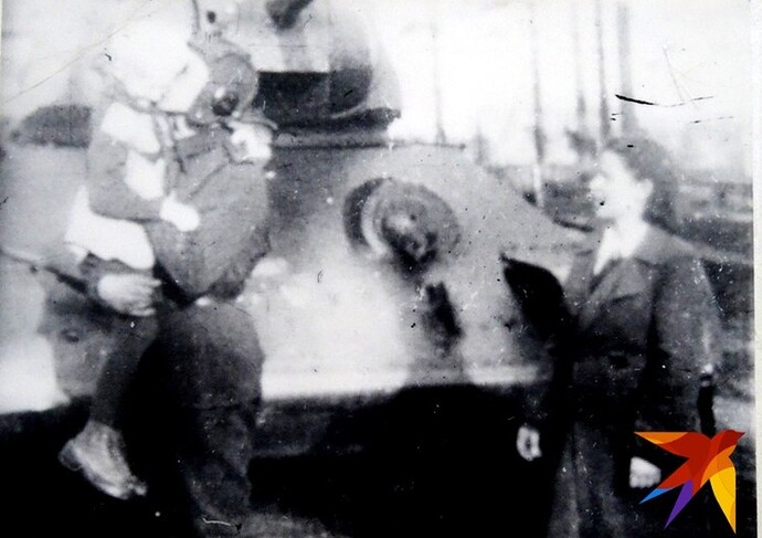
The task is to make a model that looks like this prototype:
The emphasis in our work will be on painting, name/dedicatory inscriptions, and weathering. The subject of compliance with the material and technical part is not addressed. Without figurines.
Legend: “The tank, which had just been completely assembled, was driven out of the factory workshops and driven to the school building for a rally of teachers and schoolchildren who collected money for the construction of the tank in order to solemnly hand it over to the troops.”
What do you have to say about all this?
5 Likes
So, I’ll continue.
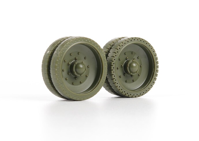
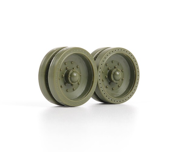
Work is underway with the road wheels. To make them more expressive, I decided to drill shock-absorbing perforations and cut the tread.
I would like to immediately warn you that the manufacturer positioned the perforation line incorrectly - in the middle of the rubber band. In fact, it should be closer to the edge of the disk.
Reference information.
- The diameter of the perforation on stamped discs is 14 mm. A 0.40mm drill bit is ideal.
- The diameter of the perforation on cast discs with tread is 15.6 - 15.8 mm. A 0.45 mm drill bit will work well.
- Unfortunately, I don’t know the diameter of the perforations on stamped discs with a tread.
- Perforation holes are through.
I tried making holes with a diameter of 0.4 mm, but I didn’t like it. It didn’t look very convincing. Most likely, this is due to the fact that the perforation line is shifted towards the middle. If it were closer to the edge of the disk, then the holes would be closer together and would look different. Therefore, I decided to make holes with a diameter of 0.45 mm.
On stamped discs with a tread - by analogy with cast discs with a tread. In general, I drill perforations with a diameter of 0.45 mm on all road wheels.
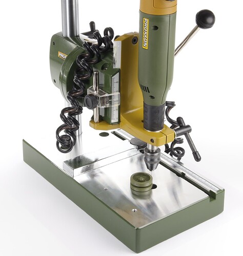
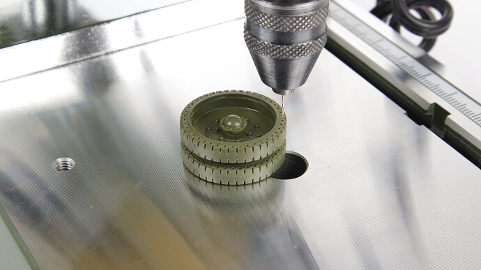
To drill the perforation I used a Proxxon drill stand, a Proxxon drill, and a pedal for it. Without a pedal, high-quality drilling cannot be done! Don’t even try. I tried it - it turns out nonsense. Only in this sequence: position the road wheel and the drill bit relative to each other - install the drill bit in the hole - press the road wheel to the frame - check the accuracy of the drill bit again - start drilling.
I cut the tread using small saws. I was not able to achieve 100% similarity, since this requires special tools. But, what has been done has already transformed the appearance.
I think it was worth it.
13 Likes
Holy cannoli! That’s dedication! The look is definitely worth it but that is a huge amount of work. Vlad, you are surely a highly skilled craftsman and a very serious modeler to do this to all of those tires. I’ve never seen anybody do this before.
3 Likes
Amazing impressive improvement!
3 Likes
Matthew, Wade! Thank you!
In this situation, I considered that such improvements were simply vital. They significantly add realism. Especially in our case, when we will have very minimal weathering, and I need to try to visually highlight every detail of the model as much as possible.
Yes, it takes just a huge amount of time. In the photo - everything is just a captured moment. In fact, I’ve already spent 15 hours. And I still have to spend the same amount, since I only did half the work. But when I “signed up” for this job, I stocked up on a huge amount of accuracy, perseverance, and patience. 
2 Likes
I can’t quite be certain if you’re drilling right through each pair – I hope so, that’s only around 460 holes in total… 
1 Like
Tim! Yes, I drilled all the holes right through. Each disc has 42 holes. Accordingly, on each road wheel, there are 84. Well, in general, on 10 road wheels, there are 840 holes. 
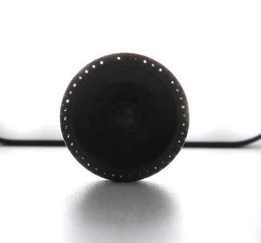
Where it was possible to glue two disks together very accurately, and the drilling was very neat, you can see this picture:
I drilled the already assembled road wheel on both sides. The holes coincided so clearly with each other that the drill, passing through one half, could clearly enter the already drilled hole in the opposite half of the wheel.
It’s actually not that difficult. Of course, at first, not everything worked out smoothly for me either. But, after some training on the inner disks of road wheels, it began to turn out more or less normal. It took me less than half an hour to drill one disk. Most of the time is spent on further processing, grinding, cleaning, tread cutting, etc.
5 Likes
Work on the road wheels, drive wheels, and idler wheels is complete.
Time to analyze the work done.
All the work on improving the road wheels was done with the goal of giving them a more realistic look, highlighting them as separate parts of the model that attract attention.
The work was based on data from my own measurements of museum exhibits.
What did I manage to do?
I managed to change the appearance. Now the road wheels are more or less similar to the prototype. They did not become copies but became more similar.
What didn’t work?
-
It was not possible to fully make the holes in a perfectly cylindrical shape. This happened because the diameter of the recesses with which the model manufacturer tried to imitate perforation was larger than the diameter of my holes. And very soft plastic. Therefore, a chamfer was constantly formed, on which burrs constantly remained. Even repeated cleaning with a drill by hand did not help. To get rid of this problem, I need to grind the plane of the “rubber bandage” until the hole has a clear cylindrical shape. It is not worth making holes of a larger diameter, as this will clearly not correspond to the prototype and will be very noticeable. The softness of the plastic also played a negative role. When I cleaned the holes with a drill bit by hand, when there was excessive pressure on the drill bit, the plastic shavings coming out from the back side literally crushed the plastic along the edges of the hole. The photo shows the yellow halos of crushed plastic very clearly. Melting the edges of the holes with glue did not always give the desired result.
-
Tread. The tread cut I made is far from reality. In fact the tread grooves had a very distinct corner shape. To solve this problem I need to use a special tool. Some kind of micro-chisels that could be used to pick out plastic. It is to pick out, not to cut through.
-
Inaccuracy of drilling. If you look closely at the photo, you can see that there are mismatches and offsets, and some holes are not made at right angles. This is due to the fact that a road wheel glued together from two halves, no matter how rigid this structure may seem, still had its own plasticity and bent slightly when drilled. It should be noted that the hub covers must be glued after drilling the perforations since they protrude slightly beyond the plane of the disk and do not allow it to be pressed completely against the frame. To solve the problem of inaccurate drilling, it is necessary to drill the wheel halves separately (not on a fully assembled road wheel). And I need to come up with a device with which they could be rigidly secured before drilling.
6 Likes
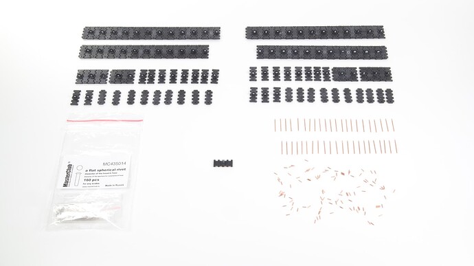
The next stage is the tracks.
I’ll try to do something with them.
2 Likes
Finished working with the tracks.
6 Likes
Hello everyone!
Finally finished additional work on the hull.
There was a lot of painstaking work, which took a huge amount of time.
All changes and innovations are in the photo.
8 Likes
Hello, friends!
I’m starting the most interesting part!
Despite the catastrophic lack of time and fatigue from daily physical work, I consider it necessary to comment on this stage of assembly. If before this there was boring and tedious work, which there was no point in describing, now an important stage has come.
So, let’s go.
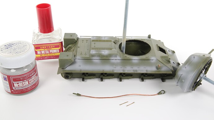
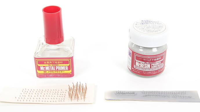
All metal parts were primed with metal primer. All places where two-component epoxy putty from Tamiya was used were primed with resin primer.
The hinge pins were also primed.
The resin rivets from Master Club, designed to simulate the heads of the hinge pins, were also primed.
And again I stepped on the same rake!!
The primer for the resin seems to have gone bad. And she’s already exactly 10 years old. No matter how I fought with it, I could not achieve a normal spray. In the photo, you can see pollination and small droplets. All this is the result of the expiration date.
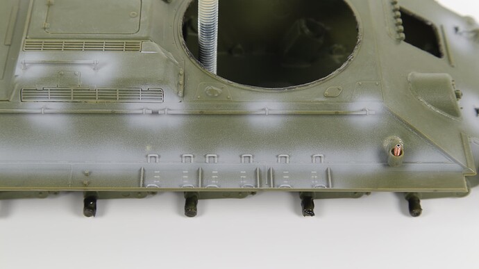
Once again the idea that priming is simply necessary is confirmed! All the flaws and shortcomings, poorly executed work are immediately visible.
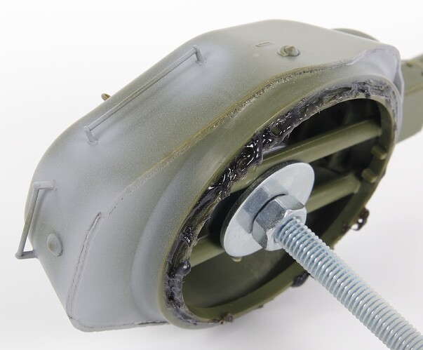
The photo shows how sloppy I made some of the welds. This became visible only after priming.
On the tank turret, the situation with welds is also the same - 50 to 50. Not to say it’s bad, but it’s far from the best option.
6 Likes
Vlad, it’s great to see an update!
I maybe missed it earlier in the thread, which kit & manufacturer?
2 Likes
Wade! Thank you!
This is Zvezda 3689. T-34-76 mod. 1943 Uralmash (UZTM).
3 Likes
Hello everyone!
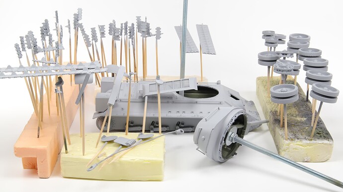
The process is moving. And finally, I primed everything!
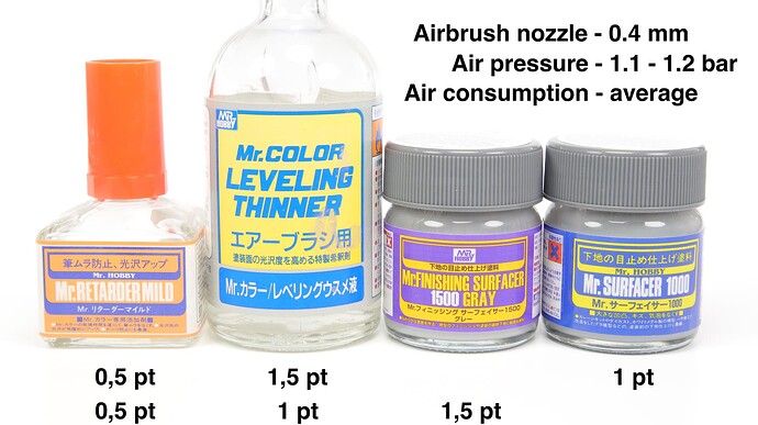
I used two types of primer, thinner and retarder. For the lower part of the tank hull, road wheels, drive wheels, and idlers I used Mr. Surfacer 1000 primer. For all other parts and the upper part of the tank hull and turret, I used Mr. Finishing Surfacer 1500 Gray. In the photo, I indicated the main parameters of the tool and the proportions of the mixtures. I will note that in this case, I used completely new (fresh) primers. Therefore, the proportions of the mixtures seemed optimal to me.
At first glance, everything seems fine.
But, friends, this is not so!
Upon closer inspection of the completed work, “terrible things” begin to happen!


And here I begin my favorite pastime

- SEARCHING FOR DISADVANTAGES AND IDENTIFYING THEIR CAUSES.

6 Likes
Vlad, I’ve studied an enlargement of the finished photo and I can’t find any “terrible things”. It looks beautiful. What are you talking about?
2 Likes
Matthew, hi!
When I myself looked at the finished result immediately after priming, it seemed to me that everything was fine. But then I began to carefully examine everything and realized that there were a lot of shortcomings and mistakes in my work. I took a lot of photos, using which I will analyze all my mistakes and other nuances. This will be discussed below.
2 Likes
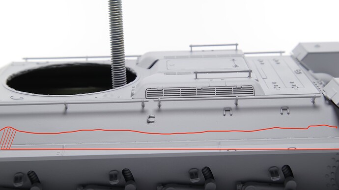
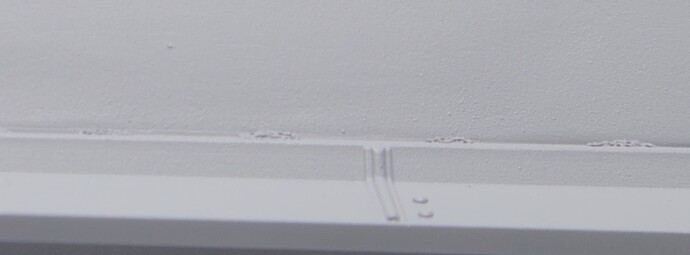
So, the first thing I would like to point out. As you may have already seen, I used Mr. Resin Primer Surfacer epoxy primer. It was expired, and after drying there was pollination and small lumps left. The correct way would be to sand them off. But I mistakenly believed that a new layer of primer would dissolve the previous one and the surface would be leveled. Unfortunately, this did not happen. More precisely, it happened, but not everywhere. As a result, the entire surface, where the first layer was Mr. Resin, became rough, “sandy”. There is no talk of any smoothness of the surface. Moreover, in some places, this “sandiness” has become even more exaggerated.
Based on all this, the first conclusion can be drawn:
Even though this is a primer, the surface must be carefully prepared before using it! Before each subsequent layer, everything must be carefully sanded.
6 Likes
