Hello Don
16 days without a word from you, I hope everything is okay with you. Would be nice to hear that you are fine
2 Likes
He just posted on his 1/16 Das Werk Stug build
2 Likes
Thank you. Sometimes it’s better to look right before asking✌
But most time I can see the new posts I’m interested in, this time not
3 Likes
Hey Marco I’m doing better still some headaches. Had most of the Staples removed the other day. There are 2 that they couldn’t find yet probably under all that dried blood. The hospital didn’t clean me up practly zero % It’s all coming off a little at a time.
I just put the wheels on the DasWerk Stug III build.I’m cleaning up the track.
I’m looking forward to finishing it , but I’m not going to rush it.
I have the 1/16th. Ontos lined up next , The track in it is a soft flexible plastic , I hope it’s not like the Dragon Track.
Regards
Donald
7 Likes
That’s good to hear, I’m happy that you feel better. Hope it goes on like that.
Have a good time✌
2 Likes
I’ll look forward to that, its on my I want it but not sure list. Waiting to see what AHHQ anounce first.
1 Like

Hey,
Great day…i am seeing some warpage on my back (part #“M”.)
Otherwise good to go so far.
1 Like
Those triangle tunnels are actually the fuel tanks and side walls of the engine compartment, and should be painted accordingly. Also, retstraining straps for the fuel tanks can be added. Indeed, may be hard to see, but there are those judges with their darn flashlights.
1 Like
I would suggest, if you want to somewhat fill it in…use acrylic sheet and put the curve in that way…thats what I’m going to do. Have fun.
1 Like
If by “triangle tunnels” you mean parts J6 and J7, they are not the fuel tanks.
The fuel tanks are not visible from outside.
Those parts are air intake ducts that protect the fuel tanks and lead to the radiators.
See : Tiger radiator ducts
David
3 Likes
Be aure to ensure the right side of the breech is steel in cilor.
1 Like
Actually this is correct. I have a pic of yhis exact hatch, showing this exact placement. Email me and I’ll send it .i am sorry not sure how to add it here.,
1 Like
I am sorry to dissagree. The sides of the “tunnels” are - the inner side is of the outerside of the engine compartment wall…while the outer “tunnel” wall is the innerside of hull. The fuel tank IS viewable from the top looking into the hull. Also notice the fuel filler tube runs directly down from the filler, as depicted by the plastic tubec running downward. How do i know? I’ve seen it first hand.
Have a nice day.
1 Like
It is pretty obvious from their shape that they are duct work; anyone familiar with German engineering, especially things such as air-cooled Volkswagens, will see them as such. Seeing as how there are no parts included in the kits to represent the fuel tanks, I am not sure how you think you can see them just because they included the filler pipe which goes down PAST the duct work.
I hope David doesn’t mind if I borrow a pic:
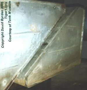
That triangular form on the left is the duct work; the object on the right is the fuel tank. The duct sits over the tank, thus obscuring it from view. It would not be considered wise by the crew to discard them as they served to cool the engine which was very necessary. As a former VW Type 2 owner I can assure you having all my duct work in place made a huge difference in the operation of said vehicle.
Take the L. Don’t insult Mr. Byrden.
1 Like
Thanks, but as you may not realise yhe duct work is the “sides” and not a tank coverage. Lets becfriends and agree to diagree. Have a great day.
1 Like
Ok, i give up…you are CORRECT. My bad for not doing greater research and relying on non reliable info.
1 Like
Not to seem argumentative and/or rude although I have no issues with being such, actually I do realize how it works; you are the one not understanding how the duct pieces work. The ducts serve to direct the hot air up and out of the vehicle rather than blow it toward the fuel tanks and around the engine compartment which would interfere with their performance. The boxy end of the space will create vortexes trapping some of the hot air.
I can see the kit instructions on my screen right now: the ducts come down and pretty much mate up to the radiator. There is no appreciable ‘side’ from the outer and inner hull plates to act as ducts; only the actual duct is filling the space. And while not ‘tank coverage’, the ducts do cover the tanks from view as they sit between the tanks and the exhaust grates from the vantage point of someone standing on the engine deck and looking down.
You aren’t the only one who has seen things first-hand; David’s web site is full of articles where he made his own measurements. He doesn’t spout nonsense or he wouldn’t be tolerated here and no one would heed his advice on the topic.
I happen to be familiar with German air-cooled engineering having owned and performed maintenance on various vintage VWs of all types, as well as the occasional Corvair.
I also can gather evidence to support the function of the parts represent by J6 and J7, but I don’t need to because I believe I know why you think you see what you see.
You saw a Tiger that was missing the ducts.
And while I was writing all that I see you submitted a response. Not meaning to pile onto you, but that really just took looking at the illustration a little longer and the connection to how it works IRL would have kicked in.
You rustled my jimmies when you took on Mr. Byrden, who I feel has earned a reputation for his work on the Tiger that benefits us at this site.
2 Likes
That photograph actually depicts two Tiger fuel tanks piled one on the other, in the Bovington camp workshop back in the 1990s while Tiger 131 was being restored.
David
1 Like
Spare Tiger intake with duct, Saumur museum 1990s.
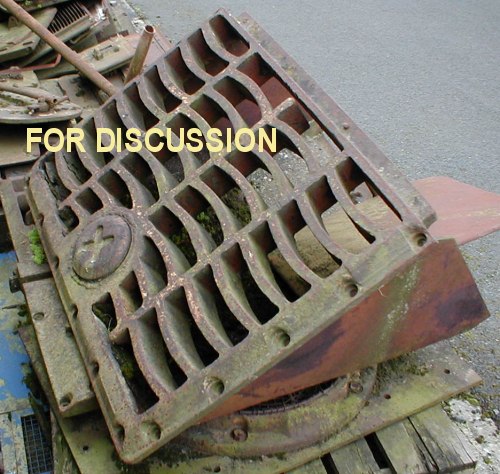
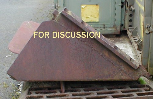
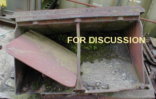
David
1 Like