Well gang, I’m back! It was a very nice trip all the way around including all the family visits. The Big J tour exceeded my expectations. Ray was unable to join us, but he assigned two guides to me and my friend, Bruce. The first was Libby who had an encyclopedic knowledge of the ship and is their media director (she helps Ryan put together those 800 videos), and the second was James, who was an ex-navy man, (although on carriers) and was near my age.
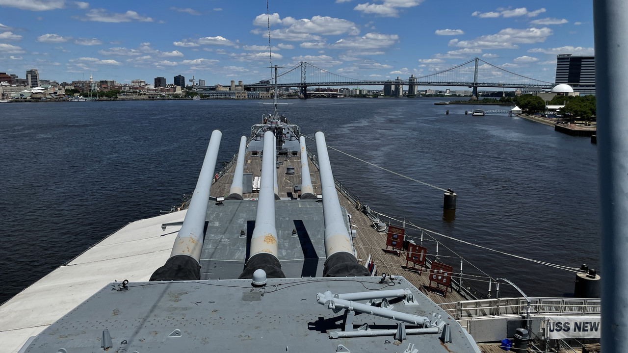
Here’s the proof we were there. This was from the 5th level up in front of the Auxiliary plot bridge. That’s the Ben Franklin Bridge and Society Hill area of Philadelphia. The weather was PERFECT! It was in the low 70s with no humidity. it made crawling around in non-climate-controlled areas very acceptable.
We were given carte blanche and access to anywhere we needed to be. I did get into the sighter’s compartment on turret #3 which is NOT open to the public. The hatch was secured with a padlock which was opened for us. This turret was not restored and you were quickly made to realize just how much work restoration entailed. I answered almost all my questions about the sighting compartments and the missing data about the gun compartments themselves. I will elaborate as I go on.
I was so concerned to remember my tape and clipboard that I forgot my iPhone in the car. The car park was quite a walk from the pier. I was at the hatch to the sighter’s compartment when, reaching for my phone, realized that I didn’t have it. DOH! Bruce was kind enough to go back and get it. Meanwhile, I was able to study what I was seeing in greater detail. As it turns out, the tape and clipboard were completely unnecessary. All of the measures I needed to make were right on my phone. I have measuring apps in addition to the scanning one.
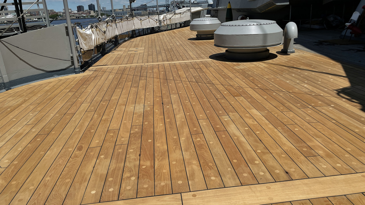
The ship is getting all new teak decking on the main deck. It’s an $8mm project. Here’s the mid-ship decking. It’s beautiful. The foredeck teak is a wreck and is slated to be installed next.
We were able to get to the powder and projectile flats easily in the restored #2 turret. This is the one that has the normal stair cases installed to handle the public. If it weren’t for them, it wouldn’t have been possible for me (I think) since access from the powder flat upwards to the projectile decks is via a set of metal rungs welded to the central column leading to a small hatch in the projectile deck center compartment’s floor. In the case of #2 turret, which is one deck deeper, the ceiling height in the powder flat is two decks. There is a storage mezzanine that surrounds the powder flat where additional shells were stored. That would amount to about 20 feet of vertical rung ladder to ascend to the lowest projectile flat and that wasn’t going to happen. We did walk through to the un-restored powder flat in #1 turret just for fun. We also got a tour into one of the magazines.
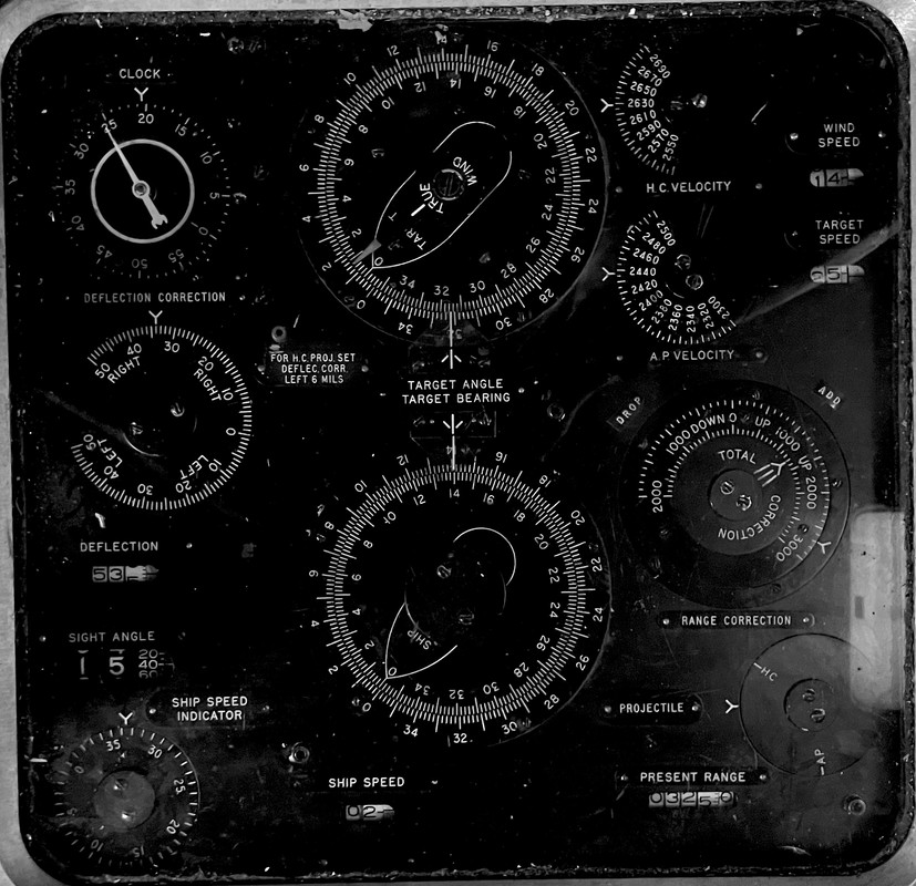
I found that there is only ONE access pathway from the turret hatch into the ofc’s booth. For some reason, I assumed (incorrectly) that since there were two hatches underneath the turret’s rear that there were two paths. No one knew what that 2nd hatch on the right side was for and it’s never opened. That means I have to reprint the entire ofc’s booth assembly. I also got a nice vertical picture of the instrument face of the ballistic computer and will be able to make a decal out of it.
I cropped it and did some photo enhancing of it.
We toured all the flag officers’ compartments, the flag bridge, nav bridge and finally the open roof at level 5. We didn’t climb into the air defense tower, although we could if we wanted to. We were supposed to be there for one hour. Instead we were there for 2.5 hours.
At the end, we finally met up with Ryan and discussed where the finished model will be displayed. We decided that it should be on the main deck so it could be seen by all visitors, especially those with disabiliities who may not be able to negotiate to other levels.
My first use of the scanning app was in the projectile flat. I was able to take a reasonably accurate scan of the entire projectile hoist (360°). In addition to James, there was a volunteer mechanic working on some stuff. Both gentlemen were completely gobsmacked that I was able to made that image. They’d never had a tour client that a) had such capability, and b) knew so much about the subject. James was very happy because of our access he was able to tour places he is normally not allowed to enter.
I found that the hoist has three legs, not four. I am able to make measurements directly on the 3D scan in the phone, so I now know that the leg width is 8" and 7" deep. I found that the middle rotating deck is 30" across. I had it at 29" on my prints so we’re really close on that one.
Here’s a screen print of some of the projectile scan.
The app also lets you export the scan as a movie. I’ve made a compilation of the projectile hoist and the powder trunk, loading area and operator’s booth and turned it into a movie. It’s now on YouTube albeit a lower resolution. The real version is very sharp. You see a lot of partially formed shapes in the images. They don’t matter. All I cared about was the hoist in the center of the display. Same goes for the powder trunk. There’s a lot of garbage in the image, but I’m not looking at that.

I’ve already started re-drawing this critical piece to make a more accurate print.
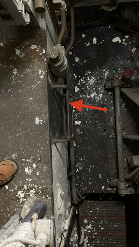
I was completely off regarding access to the side gun compartments and the sighter’s stations flanking the side. While my actual sight equipment was scaled pretty close, I had the positioning in the compartment in which they sit not so correct. I also had the access to the gun chamber from that side aisle completely misunderstood. There is NO side door or hatch opening to the compartment. It’s actually a large squared-off opening in the entire bulkhead. And I knew there had to be steps of some sort to get from deck level down to gun loading platform level, so I drew steps. But they didn’t actually fit. That’s because, instead of steps, there are three welded ladder rungs projecting out from the lower side wall of the gun girder.
This image is of the right gun compartment standing on the gun girder in the side aisle big opening looking straight down to the ladder rungs (arrow). You can clearly see that this is an un-restored place and generally never open to the public. The paint peels due to the changes in temparature and humidity in the un-climate-controlled space.
The middle gun also needs steps leading down from the ofc’s booth door, but it’s not a solid stair. Instead is a lightly constructed metal inclinded ladder. As a result of these discooveries, I will have to reprint all three of the rear gun chambers.
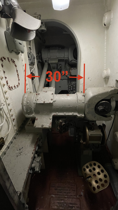
This is a highly distorted pano shot of the entire center gun compartment taken from standing on the gun captain’s loading platform. You can see on the left the metal ladder coming from the door to the ofc’s booth. I was finally able to measure the width of the powder door that’s open in this picture. It’s 52" across and a littel over 28" wide.

The gun captain’s controls and communication devices are on the edges of the side compartment access portal. The center gun was even more interesting. There is a long alcove where a person can stand on the side opposite the powder door. Within this alcove are all the same devices plus a weird little hatch nestled into the foreward corner. These layout details were unmarked on the floor plans I had. It’s no wonder I missed them.
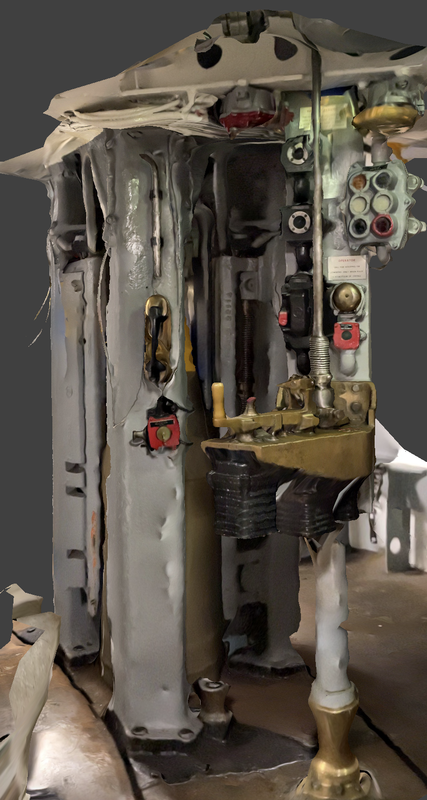
The sighting compartment access door was much smaller than I had. Very little! And the telescopes went clear from one side to the other so you can’t walk around them. To access the forward two operator positions you walk UNDER them. The sighting compartment floors are on the same low level as the gun compartment’s and again, there are ladder rungs welded below the door to climb down inside. There are two more tranverse bulkheads in this compartment that have arches under them so the crew can pass underneath, and the sight regulator’s position far forward, is reached by stooping under the forward telescope. You CANNOT have claustrophobia and survive in turret operations. Nor can you be fat! These ships were manned by skinny 18 year-olds.
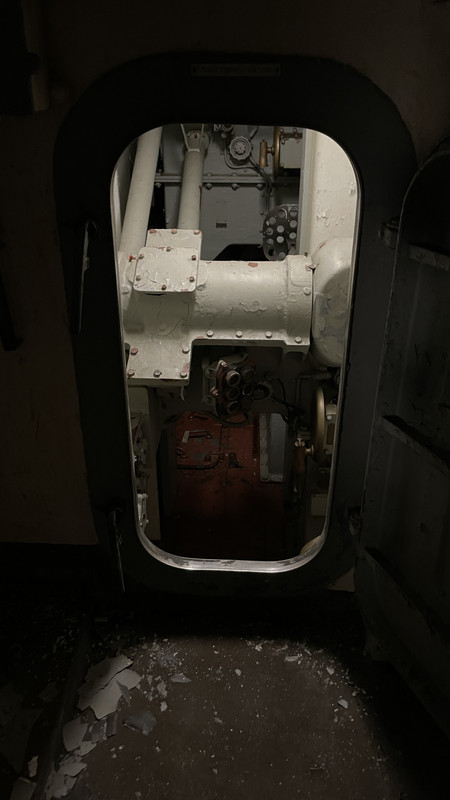
I didn’t climb inside. It wasn’t necessary nor did I want to. But this view shows the way under the telescopes. I did reach in and get a tape measure on the telescope. This is an un-restored space. Note the brass seat. Must have been a tough place to work in the South Pacific when the big guns were firing. They’re supposed to sound as loud as a shotgun blast from inside.
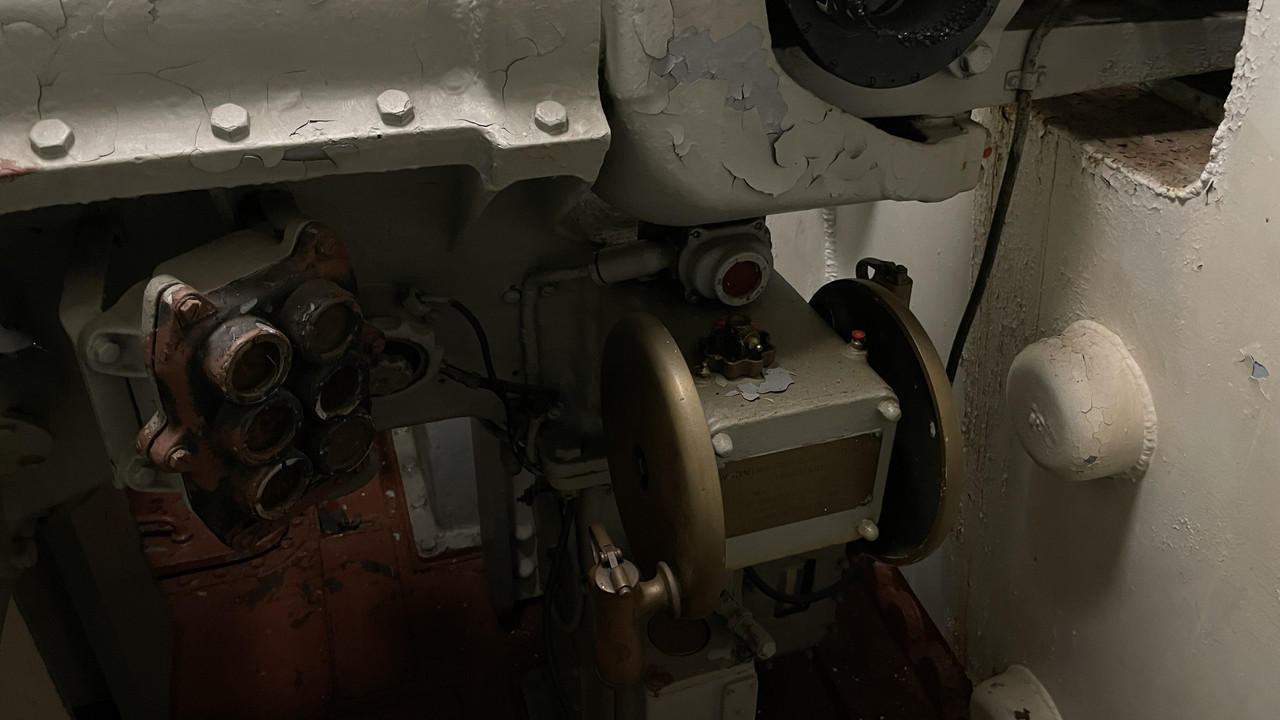
This is the pointer’s handwheel. Notice it has a gun trigger on the handle. All the sighting stations, both in the gun house and those on the electric deck have firing triggers. The 6-light innuciator shows the firing status of the guns. These handwheels are geared to the sight systems below in the electric deck and probably to the firing computer in the ofc’s booth.
These findings filled in some gaps in my understanding and will make a better model.
I made a full view scan of the entire powder-deck-level of the powder hoist chutes, powder loading trays and the lower powder hoist operators station. I found that the center and right powder trunks (and their operating booths) share a common metal sheet between them. This is an important finding which renders my current prints of the operating booths wrong and explains some of the reasons why i couldn’t get the spacing correct. The other reason is simply the thickness minimum that I have to hold to make viable parts.
The door bulkhead is a single sheet also meaning both booths must be printed as a single print.
The loading trays, which I though were free-standing pieces of equipment are actually built right into the side of the powder trunk and made of brass. Again, this changes my powder trunk print. I was going to reprint the entire trunk anyway so I’m not losing anything here. I may have to print the gun girders over again to accomodate some of the changes and that’s a bummer since it uses a ton of resin.
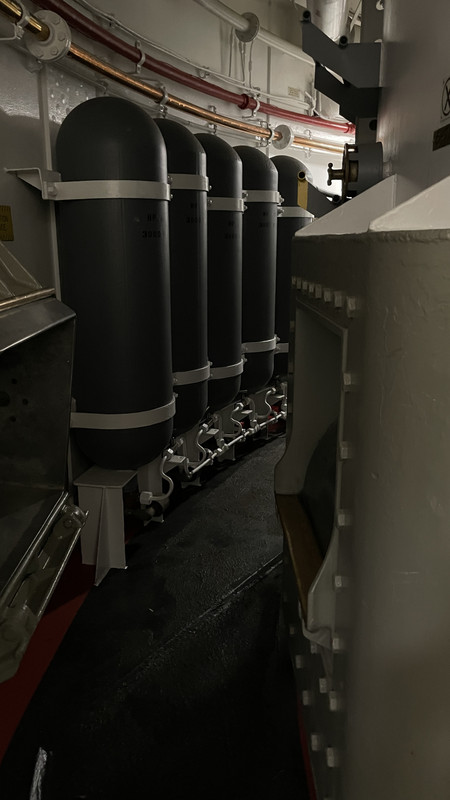
I got a detailed shot of the annular space between the magazines and the inner powder deck walls including the input side of the powder scuttles and the air bottles lining the walls. The air is for the ejection jets in the guns themselves. I also got a scan of the dunk tanks used to deactivate any powder bags that rupture. With these images, I think I can finally get all the aspects of the build right. I believe they install a chute across the space from out outlet of the magazine scuttle to the inlet of the powder room scuttle so they don’t have to lift the 110 pound bags any more than they have to.
I also learned that the crew could only work in the powder flats on 15 minute intervals. Apparently, the smokeless powder in the bags gave off ether that would render the crew senseless if they remained there for longer periods.
Turrets are tough places to work. Although one could imagine working in the fire rooms of the 8 boilers, being station in the shaft tunnels, or having to load the quad 40mms on the upper decks wasn’t much fun either.
All in all, the tour did exactly what I wanted it to do. I had developed a whole list of questions and had them on my iPhone. I answered all of them. I also realized at about the same time I started using the scanner, that I could put all the answers directly next to the questions and didn’t need the stupid clipboard either. It made going up and down inclined ladders much more difficult having to hold the railing AND the clipboard at the same time. It was my traditional brain getting in the way of my digital one.
Now I’ve got to get back to the drawing board, literally and figuratively.