Takom Iowa Class Mark 7, 16"50Cal Turret with Full Interior Start-to-Finish

Maybe I will or not. They’re not that easy to visualize.

With the full court press to get this thing down by December 25, I had another short, but productive, Saturday work session.

Here’s a comparison of the Badger Model Tech Early WW2 Haze Grey and the Life Color Late War Haze Gray. This Life Color is the correct version in my estimation and is the one I used on my Missouri.

So I shot the whole model and here’s what it looks like.

It’s better. The Life Color airbrushes beautifully. After it was dry to the touch, I pulled the turret carefully off the base plate, easing as little slack in the LED leads that I fished yesterday and removed the masking. I was rewarded with no leakage.

It was time to fasten down the shell permanently. And Boy! Am I glad that I chose to screw it on instead of gluing. Gluing would have been almost impossible. There’s so much stuff inside and little things here and there pushing in the opposite direction, that unless I clamped and epoxied the whole deal, it would not have stayed together. As it was, I did have to apply significant pressure in the rear to get the pre-drilled and hardened (with thin CA) screw holes to line up. The fronts also needed some coaxing to settle in, but I prevailed. I also knocked off one of the rangefinder armored ears, the port side front ladder and the shell derrick. All were fixed.

There’s a lot of stuff going on it there.

Before I could button up the rangefinder armor I had to put in the RF optics. And before I did that I had to do the optics themselves. I used Molotow Chrome, folloed by a lens of Bondic, and finally Tamiya Clear Green.

Then it was time to fit them in. And of course they were about 1/4" too short. Again, a screw up that is a product of designing them without the actual model dimensions. At first I was going to extend them using Plastruct butyrate pipe, but then I remembered that I had extra optics. Glad I didn’t throw them out. I needed the ends since one has a male stub with a half-moon slice and the other the female version of the same shape.

If you can’t see the optical head in the open RF shield there’s no point in having it there are all.

I measured the shortfall with the caliper and transferred this measurement to the spare. I then needed to make a square cut of the spare to create the extension. I could have chucked it my Taig Lathe, but it’s all stored away and too much of a hassle to resurrect it just of this one thing. Instead, I gently chucked it in my drill press with the cut line just sticking out. I used a razor saw to inscribe the cut. I didn’t go all the way through since it was unnecessary and could go flying off somewhere. The cut was deep enough all the way around that i could hand saw the rest. I then lightly sanded the newly cut face for a good joint.

The oddball shape of the extended part is not visible at all. I put the corrected optics into the shield and was rewarded with a good view of the lens.

I closed off the ends of the RF shields and took another picture.

The only thing left to do on the entire turret shell is highlight the cutaway edges with the bright red and install the bloomers.

The kit has some nice gun plugs which are great since the barrel’s bore only goes in about 1/4" and has no rifling. The plugs are red and on Monday I highlight the center nub with some yellow.

Last thing I did was demask the gun barrels. No leakage. The polished slides on the real guns are never this color since they’re lubricated and have a much browner cast to them. I may dull them down with some Tamiya Clear Yellow mixed with a little Clear Smoke.

On Monday I will also be painting the bloomers and permanenly installing the guns. I’ve been handling the wiring a lot and sincerely hope that all the circuits are still intact. I used Bondic as a strain relief so tension was not directly on the copper foil. I did notice one of my my Bondic “cable clamps” came loose under the turret shell roof and is no longer fixable. I hope this was an isolated incident. In most places I can reach the circuitry.

I’m predicting the turret stack will be assembled on Monday leaving the rest of the week to install a off-on switch in the wood base and build the enclosure. And maybe make some crew. If the weather is poor we may postpone the trip. If that happens and I can’t deliver the model until Spring, it will give me time to purchase those perfect 1/72 scale USN crew for the insides. That would be the silver lining.

5 Likes

Things are moving fast and furious. I was working on a couple of fronts today all progressing forward.

Areas of attention were: the central column, bloomers, power switch for base.

I did the bloomers first with a mix of Tamiya Rubber Black and NATO Black. I used 3M blue tape to mask the little flange at the rear of the slide area and the tape pulled paint of the barrel. I resprayed and fixed it. I wondered why the airbrush was gumming up so badly. I inadvertently used IPA to thin the Life Color paint. Like Vallejo, these acrylics not only don’t thin with alcohol, they form rubbery blobs that clog airbrushes. I realized my error, cleaned up the mess and then thinned it with AK universal acrylic thinner. Bloomers are not glued here. I will glue them to the turret first, then install the guns.

A critical step was figuring out how long the central column needed to be. The column I was using up to this point was just a guesstimate that didn’t take into account the actual combined depth of the wooden base AND the 3D printed mounting flange. I measured that combined distance, assembled the stack with another, overly long, column and marked this depth.

Here’s a closer look at that mark.

I took this piece and cut it off at the mark on the chop saw.

I then had to cut the various access points in the column for the wiring harnesses to go under the base. I just went at it with the carbide router. They didn’t to be pretty since they’re out of sight (for the most part). I then clamped on a forceps and sprayed it flat white. I almost blew it by starting to run wires before painting. I caught myself after just doing one wire set. I had to keep my wits about me when figuring where the access ports were going to go. They had to align with the general direction that the wiring was approaching the column.

While this was drying I got to work installing the missing power switch in the wooden base. While I felt bad about hacking into the beautiful piece of woodwork crafted by my friend Bryant Mitchell, it was necessary. I have a few left over double pole/double throw toggle switches from building my model railroad. I only need one pole, and one throw for that matter, but I can use both throws by making the output come from both sides. So middle is off and switching in either direction is on.

I consider myself a pretty good solderer, but after taking this image, the outer two leads just fell off. The switches are German and I got them when first building the railroad when on assignment at Henkel in Düsseldorf, Germany. That was 1999, which makes this switch 23 years old and the terminals had oxidized. I went at them with a file and resoldered the wires correctly.

Here’s the wiring completed as of now. The circuit board is just floating there since I have to terminate a whole lot of LED leads on its underside.

And here’s the exterior.

By the time I got done this sub-project, the column was dry and the wiring could begin in earnest. I first fished the twin lead from the bottom of the electric deck (lights the first projectile flat) which goes directly from the top to the bottom. I used a piece of heavy gauge solid-core wire to fish the bundle through the access hole and out the bottom.

Some of my wires were short. I was estimating the length during the LED wiring phase, but shortchanged myself. I had to extend some about 6" just to have enough slack to do all the terminating without straining anything.

Here’s the entire mass now fed through the frst access hole. There are two more sets that need to go in. I made a large notch in the e-decks outer flange so the wiring wouldn’t affect the deck nesting. I overcoated it with Bondic to secure them before fishing. I may have to cut one more access hole for the two-wire leads from the 2nd Projectile deck.

With the harness in, it was time for another milestone; the gluing in of the column’s top into the boss under the electric deck. I used epoxy for this critical joint. It needed to be plumb in both axes and I taped it after putting a square around it to ensure it was. The boss is larger and the column was able to shift a lot.

I need to paint the foot rungs on the ladder pieces a printed several weeks back and then install them on deck at a time as I install each projectile deck. There theoretically is a ladder on the powder flat’s exposed column, but it’s completely hidden by the foreground’s powder trunk unit and therefore, I can’t get to it to install the ladder, nor will it ever be viewable. Therefore, it ain’t gonna be there.

From one angle…

And 90 degrees around. The wiring coming up the back of the electric deck is at the rear and out of view. I also touched up all the flat white that got disturbed when epoxying the pan and e-decks.

And of course something broke. Those $@T)Y)% float net baskets are just too fragile to be around this level of heavy construction. I’m going to wait until it’s just about all done and reinstall it.

Tomrrow will see the stack come together. I really think I need to build the enclosure BEFORE the stack is fastened to the base. I’m going to have to trial fit everything and don’t want the chance to bump something. So I will be building the case sooner rather than later. Actually installing the stack into the base will only take a couple of minutes. Since I have to terminate all those LED wires with the model built and on the base, I will also like the enclosure built so I can tip the entire model on it’s side or upside down without the model supporting any of that weight. Speaking of weight, resin is heavier than a styrene model. Between the mass of the base, the acres of 1/16" plexiglass and the dense model, this thing’s going to be heavy!

Stay tuned!

6 Likes

As I noted yesterday, the end game moves fast. I built the stack only to find out that the ladder rung assemblies just weren’t going to go in. The headroom is so tiny that they would go unnoticed. The fit betwen the column holes in the decks and the column o.d. that my paint job created a bind that was so tight that it removed all the paint as I got the decks down into position. I don’t want to have to pull those decks off the column to open the holes a bit, so if the paint really matters I’ll have to do some touch up painting in situ, and I’m not looking forward to that. But I got all the decks stacked and all the wires threaded through the column. It’s now wating for the cabinetry to fully cure (tomorrow) for insertion into the base. It’s still sitting upside down.

I am not gluing the lower three decks to the column or each other. The column will be secured in the flange below the base so it can’t lift up, and having some flexibility in positioning could be beneficial, especially when fitting in the shells.

And my column WAS NOT PLUMB. I cracked the epoxy joint, made a couple custom squares with relief cuts to get around the e-decks flange, and cross-plumned it. While holding it, I let a little thin CA down into the joint between the now-hard epoxy and the part. It cured quickly.

I haven’t tested any lighting after this this abusive pulling in getting everything threaded. We’ll all find out together what lights are still working.

I then built the Plexiglass enclosure. I followed all my new-learned techniques for successfully gluing Plexiglass, and it would have been perfect. It came out almost perfect. When I first started assembling the shapes I used the corner clamps that I use for gluing model railroad buildings. I also used my machinist squares to ensure the sides were square.

Before doing any of this I removed all the plastic protective film (tip number one) since it just get in the way. I also used a razor to scrape a very small bevel on the gluing side of the edge (tip 2). I then, using a Q-tip, layed down a thin film of solvent on the glue edges to help flow the adhesive into the joint without entrained air bubbles (tip 3). I then applied the solvent by holding the applicator upright and squeezing the air out, turning it over and slowly let some air in so the drips don’t come out (tip 4) and laid the pieces on wet towels to help kill the static build up that can attract the cement. (tip 5).

I realized that I forgot to tape the edges together, which I did, but didn’t remove the corner clamps. It was one of those corner clamps that absorbed the cement in the foam gripper and soaked a bit of the Plexi and damaged it. It will be in the back and it’s a bottom corner and it don’t think I can do much to fix it. I could try polishing it out, and may if I have the time. This image was after gluing and when I turned it over. I glue it up sitting on the lid and was very happy that all the edges coincided as they should.

After pulling the tape and cleaning off any excess tape goo, I got this. It fits nice and loosely on the base which I wanted. i didn’t want any binding when opening and closing.

I put the graphics on the back of the rear panel holding by static charge to see how it would work.

The model won’t block these much so I may go with this idea. My genius #1 grandson suggested to do something different with the text, and as I usually do, I will take his lead. He’s graduating U of IL engineering and already has a nice job. It’s takes a while for acrylic joints to fully cure, so by tomorrow I can handle it. I’m going to insert the model into the base tomorrow and do the wiring. I tried the deck piece and guess what? It doesn’t work. I designed the entire model without this part in place. I would have to remove about 1/4" of the outer shells and the odds of that happening are zero to none. The model works just fine without the main deck and it would cast shadows on what is below it and that’s not so good. I just bought a ton of Northeastern Stripwood to make a real wood deck and I don’t have to worry about that now.

I started working on putting some trim around the vents and will finish tomorrow. The boys were in from college and we had a nice Hanukkah dinner at my daughter’s house tonight.

If there are no more catastropes I think I will basically have a finished model by tomorrow at quitting time. Yesterday I dropped one of the projectile decks on the concrete floor and it made a terrible “crunching” sound. There are very few times where I praise the brittleness of CA adhesives, but this was one of them. Everything that was CA’d just popped off without any resin breaking. I glued everything back together again and did some touchup painting and it was good to go. I don’t want anymore of those things happening any longer.

6 Likes

Great progress Myles, but talk about suffering for the Art – the nearest metaphor I can think of it’s like watching a record-breaking 4-man bobsleigh hurtling round the last few bends semi-sideways but just pointing enough in the right direction to straighten up perfectly as it approaches the line. The latest reinforced Impressed-o-meter’s beginning to disintegrate on its mount.

1 Like

I’d bring a full arsenal of adhesives and perhaps some spare parts when you deliver it in case anything falls off en route! We want it to arrive as perfect as it leaves.

1 Like

That’s a good suggestion which I will follow. I will also birng enough tools to take things apart if that should be required.

Someone on another forum asked what cement I’m using for the acrylic. Here it is.

The Plexi cement is a special formulation for acrylic. It’s not cheap and evaporates very fast, but it is essential.

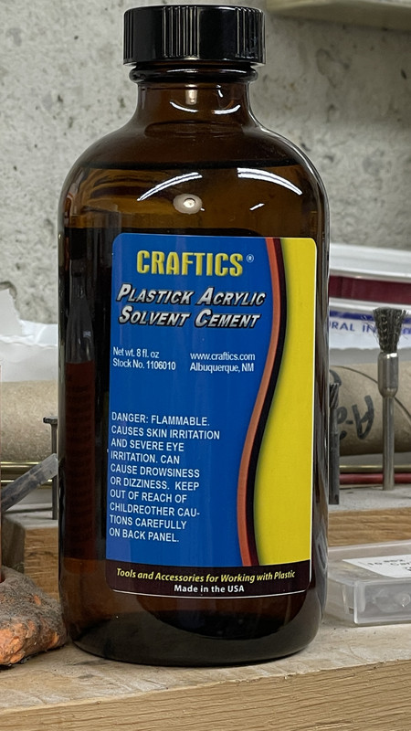
The best thing I did with the plexiglass was a) getting the measurements right, and b) having the plastics house cut the piece on a CNC mill leaving edges ready for gluing with no sanding. If you cut your own, either scribing and snapping (which I find very touch and go) or sawing using a special plastics blade, leaves and edge that needs sanding to both smooth and square the edge. While it can be done, it’s a lot of work and ripe for mistakes.

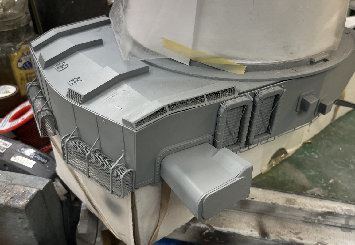
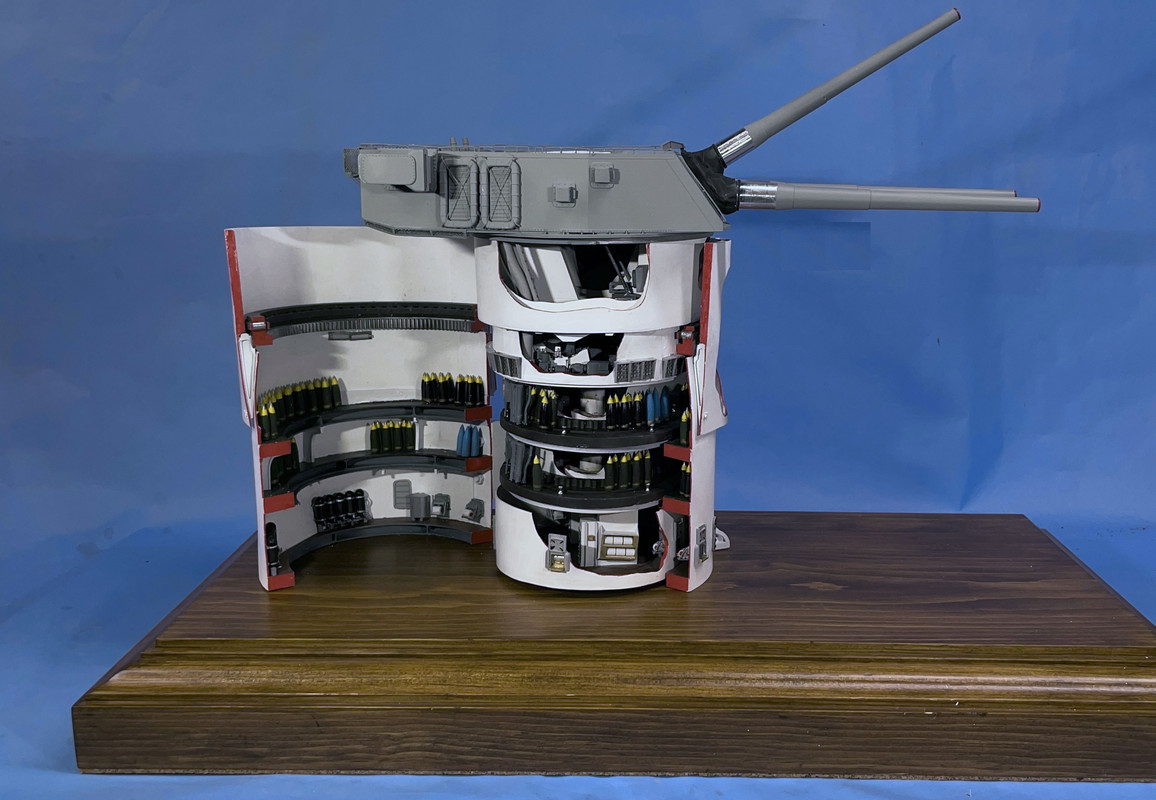
Onto today’s activities. I finished up the vent changes and added all the remaining parts, but most importantly mounted the model on the base.

I did the trim work on the vents and I’m glad I stopped when I did last night. I was rushing and getting frustrated and that leads to trouble. By doing it first thing today, it went quickly.

And the other side… Notice the errant floater net basket has been put back where it belongs. I had to fake the right side bracket since part of it got lost when it failed.

Now that I could turn it all right side up, it was time to mate the model and the base… and it WAS A BEAR! That pesky center column again caused trouble by being painted.

I put the bulkhead shells in place so I could gauge the depth of the insertion.

When I inserted the model in the socket, the center column went in too deeply… about a 1/4" or so. It wasn’t easy getting it in for the aforementioned paint problem. I had to do a lot of twisting and pushing, but not to hard, since there’s almost nowhere to grab on the model without potentially breaking something. The depth was a big problem! It forced the upper works (gun house, pan and e-decks) to drop below the top race of the roller bearing where the pan deck should be seated. I had to raise the column upwards, and in attempting to get this stubborn pole moving, I broke the mounting flange out of the bottom of the e-deck. To repair this I had to pull the top three high enough to turn them over, and had to pull the wiring harness up without having to refish the whole mass later. I was able to successfully do that and then had to go to plan B to raise the column.

Once I got the depth right I drilled pilot holes and screwed the bulkheads to the base so they would stay put.

I had the base stretched over two, equal-height worksurfaces so I could get to the undersides. I resorted to a pin punch and soft hammer to drive the column upwards in its socket WITHOUT damaging any wires. By raising it I was able to get the bottom edge of the pan deck to sit over the upper race. It needed some coaxing and a clamp to hold it for CA gluing. I glued around the backside as well.

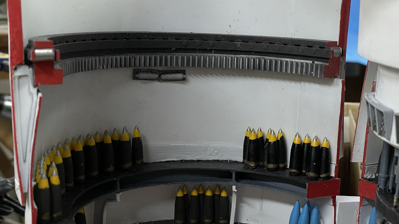
Once this was glued I was finally able to install the turret clamps now that I had the exact location of their seating under the ring gear. They are doing for the model the exact same function as the real ones do. They preventing the upper works from rising off the seat and provides additional security to holding the model in place. That ragged paint is the result of scraping the paint to the base UV Resin for a better CA joint. It looks pretty real actually.

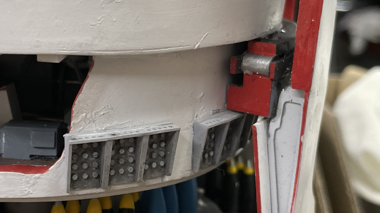
With the clamps in place I was finally able to install the last two parts: the buffers and positive stops. The buffer sits under the now-hidden ring gear, and the stops are on the barbette inner wall about 180 degrees around.

I don’t like tht they’re a bit crooked. i may have to fix that…

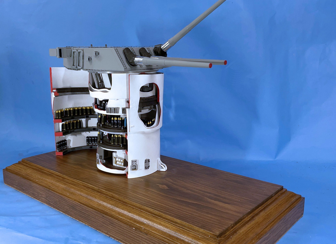
The last thing I did was add the guns. I glued the bloomers in first with Testor’s tube cement. The guns are not glued. If you have to take off the gun house top you would have to remove the guns. But the fit was too tight. My machining tolerance was very close and the paint buildup in the bore was just enough to make them a press fit. I didn’t want to press too hard for fear of breaking something unfixable inside, so I stopped, wrapped some med grit sandpaper around that pin punch and lightly sanded the bores. It worked and the guns are a firm sliding fit in. They seated perfectly and none of the elevating screws were damaged. Whoopee!

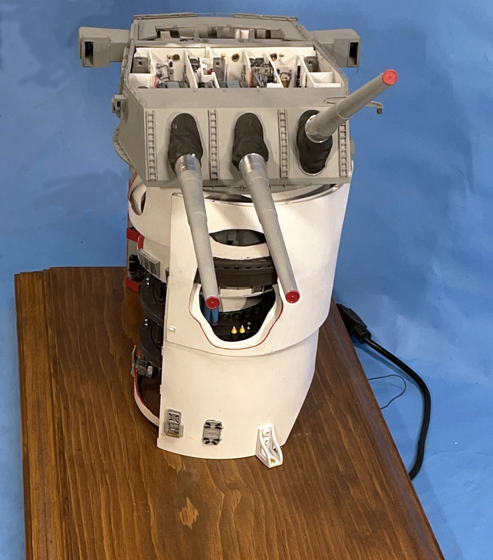
So… dear readers, the model is complete except for the lights and that takes place tomorrow. I’m still working on the lighting and that will be done tomorrow. I don’t think I’ll break anything else, but you never know.

My #1 genius grandson, revised my data sheet, making it more user friendly for museum visitors; more of a narrative rather than a technical list of items. It now describes what takes place on each deck rather than a list of item found there. He also suggested, which I have accepted, to add a QR code that directs visitors to one of my build thread on the various forums on which I post all of this. I’m going to make a separate tag with info. This way, so one so inclined can learn about the entire agonizing process.

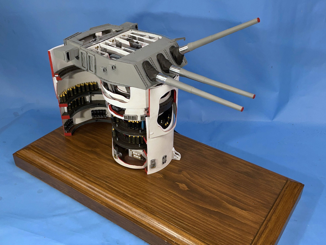
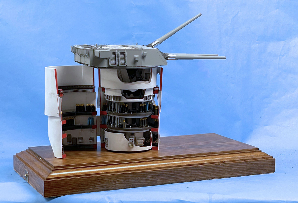
Now for some fun pictures.

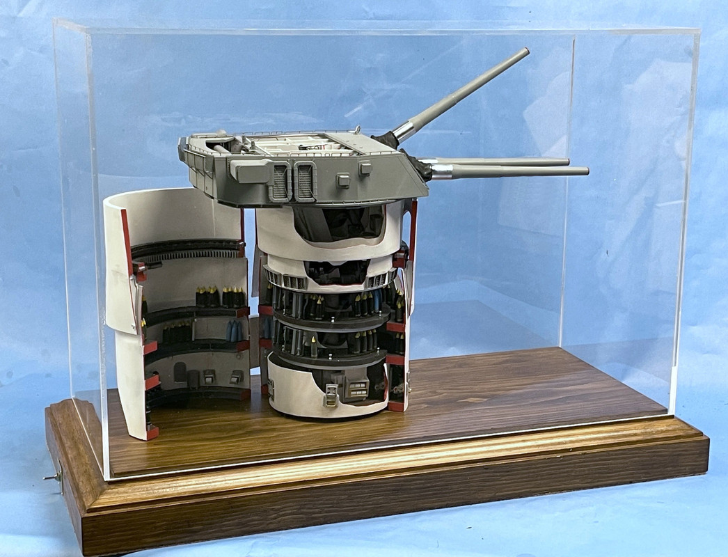
And with the case lid in place. One of my readers suggested devising a way to secure the enclosure and I’m noodling some ways to do this.

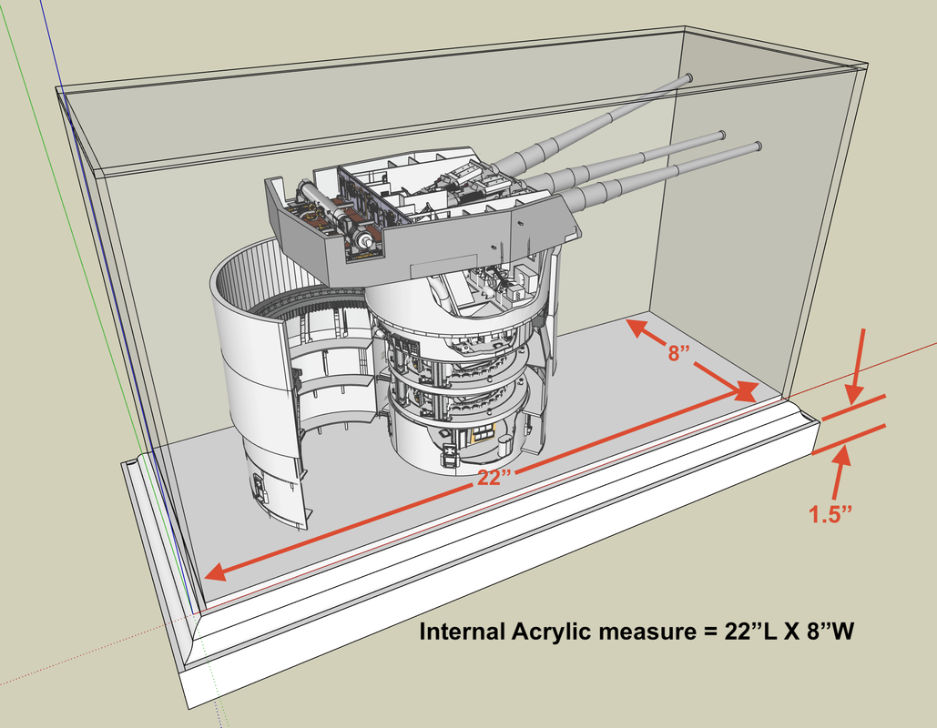
Here’s my design drawing of the same.

Tommorrow, if and when I get the lighting working, I will take some more images… and then I’ll take some more when the graphics are mounted. I will wait until all this is done for my formal end-of-project dissertation with all the lessons learned. I really need to understand all the stuff that I did wrong, especially in the desgin area. I will need all this if I’m tasked with making another one of these for anyone, including the other battleship museum ships. The turret desgin on the South Dakota class ships is almost identical other than the longer barrels on the Iowas.**

10 Likes

Today I built the case fasteners that secure the case. It secured it so well that I could tip over the model and do all the soldering, without putting any lateral pressure on the delicate model.

I bought a strip of 1/2" brass, shaped it to conform around the base’s ogee curve drilled it for the hardware and mounted it on holes drilled in the plexiglass. I have a few drilled sharpened for acrylic drilling. This is essential. A standard 135 degree drill point will bind on exiting the hole and 50/50 will fracture the valuable plexiglass.

With the case secured I had to prepare my primary work surface to hold the model lying down. I put a damp towell down to kill any static charge that would attract the clouds of dust that are contained on that workbench. This used to be where I did active building, but for the past couple of years, I use my IKEA roll-around bench mostly, and the big bench became a catch-all…but not today. That dirty tray in the front is my attempt to replicate a jeweler’s work bench belly tray to catch stuff that’s heading south. It works!

I gingerly laid the model over on its side and was rewarded with nothing on the model moving or falling off. This neatly exposed the belly for wiring hookup.

This is the mass of wiring coming down from the nine LED circuits. I had no idea if they were all intact after all the manhandling. I did periodically test them during all the other build steps when I was still able to made corrections if necessary.

I needed to tin all the leads before circuit board insertion and did so en masse. BTW: that Panavise with the wire loom dates back to 1975 when I was training about 1,000 people on precision electronic soldering. It was one of my gifrs from the program. And I’ve put it to great use ever since.

I inserted one red lead next to the CL2N3 LED driver and the other black lead onto the ground bus and soldered them. I had no idea what circuit this was but I was eager to test it. And EUREKA! it’s ALIVE!

With that encouragement I terminated the rest of the bundle and powered it again. And once again, I was very pleased that every circuit lit as it was supposed to.

It was truly a Hanukkah miracle, which after all, is considered the “Festival of Lights”.

All that was left was to re-attach the circuit board on its standoffs and dress the wiring bundle.

The last thing I did was affix the “Builder’s Plate” making the build official.

I put the model back on the photo stand and took some more images. I will take another set when the graphics are mounted on the case, and that, as they say, is that.

The case screws are loose since I will have to remove it tomorrow to install the graphics. The curator asked me today “how much time did it take?” I have not kept an accurate time log since I wasn’t billing anyone for this, but I estimate somewhere between 400 and 500 hours. Drawing time alone was probably 100 hours. If I was going to do it for fee, even at $20 and hour, we’re talking $10k. It’s why it’s hard to make a living making models. If any other museum ship wants one, I’m going to have to charge them something for it. In the next post… the last one for this project, I’m going to try and list all the things that went right and those that didn’t and the lessons learned. If I’m ever doing another I want to make it a lot easier.

12 Likes

Brilliant. Plus a few dozen other superlatives, many congratulations on completing an awesome project on time & on budget (?) – compliments of the Season to you. :clinking_glasses: Yep, best build of 2022 :trophy: :1st_place_medal:

2 Likes

Well done indeed Myles - you have much to be proud off . I have thoroughly enjoyed following this and I am certain many others have as well.
Thanks for taking the time to share this with us .
Splendid.
Cheers- Richard

Outstanding, congratulations on a fantastic build!

Thanks for sharing.

Have a great festive break!

Now that it is finished all the compliments can be brought to bear… And I doubt they will suffice to do your awesome job credit!!! As said earlier I haven’t had a clue what you were talking about half the time, but the pictures told the tale for you. The largest problem for me is that I don’t know the naval terms you are using so following you was a challenge… Happy holidays, and take a rest after finishing this epic build!!!

Congratulations on a truly epic build!:champagne::clinking_glasses:

This has been a great illustration of the modern techniques and tools available to today’s model makers :cowboy_hat_face:

Thankyou for sharing here at MSW, it has been a joy to watch. :slightly_smiling_face:

You’ve overcome all the challenges this build has thrown at you and produced a display that the museum can place front and centre!

If I may add one final thought, Myles?

Often times our mind cannot truly comprehend how big an object is until a figure of a human in the same scale is placed next to it: since your build is 1/72 it should be relatively straightforward to source some 1/72 resin figures to position thoughtfully within proximity to show off the engineering marvel’s true size :hugs:

1 Like

Epic in every sense of the word!

Congratulations :confetti_ball: :clap: :bouquet: :partying_face: :confetti_ball:

Very well done!

Fantastic build. From conceptulisation through to execution and construction, I agree with Tim, the build of 2022.

Thank you for all the kind words, encouragement and the input.

This project couldn’t have been accomplished without the help of others. I post this thread on four forums with different audiences. It is truly a global community and I was able to learn from everyone. I’ve said it before too many times, that while posting like this takes a chunk of time each night, I get back as much as I give. And it really does take a village. Special thanks go to Ryan Syzmanski, the Big J’s curator, who not only got me some critical measurements that I needed just to get started, but also the special tour I took where I got access to the non-public areas and did those amazing 3D scans with my iPhone 12 Pro. The other person is Jim Slade. Jim is doing the near impossible. He’s making 3D CAD drawings of every frame of the Iowa ships based on the actual engineering drawings that are on microfilm at the National Archives. He gave me those accurate drawings of the pan and electric decks and the outer bulkheads. Without them I was completely lost.

Here are the final, final images. I redid the graphics to my grandson’s approval and produced them to look like the placards that adorn the guns and gun compartments. I did the faux frames in CorelDraw.

Now for the “After Action Report”

The Good!

  1. Getting it finished where it actually exceeds my expectations. That’s really not that hard since I expected nothing in the beginning.
  2. Creating a very good rendition of the complicated and elusive Mark 7 16"-50 cal gun including the tiniest details of the massive yoke and breach.
  3. Designing and pre-installing all the surface mount LED lighting and the use of the circuit board to contain the nine CL2N3 LED drivers making hookup fast and error free.
  4. All the lights working after all the yanking and pulling I did to assemble the beast. The true Hanukkah Miracle of Lights!
  5. Machining the back ends of the after-market aluminum gun barrels to 7/16" so I could produce the resin gun slides with sufficient wall thickness with the mating part of the gun slides to support the guns
  6. Finally figuring a way to print the entire gun slide assembly in two parts (yoke and slide) fianlly resulting in a warp-free product.
  7. SketchUp’s ability to produce an accurate flattened-out shape which enabled me to get the circular bulkheads made out of styrene with minimal guessing.
  8. My iPhone 12 Pro’s LIDAR which enabled me to 3D scan the projectile hoists and lower powder hoist areas answering some major questions
  9. My special private tour of the ship where I finally could figure out the nooks and crannies in the gun compartments and surrounding area.
  10. Nailing the detail painting.
  11. The intricacy and beauty of the long-base range finder and how close it is to the prototype.
  12. Producing really small details in 1/72 like the powder scuttles, the inside periscopes, the auxiliary computer and all the pumps and machinery on the e-deck and elsewhere.
  13. How well the roller bearing/ring gear came out… finally.
  14. The stunning piece of furniture upon which the model sits crafted by one of my oldest friends and bass player from my college R&B band, Bryant Mitchell.
  15. Even though it was an awful experience, the way the open bulkheads worked out as a way to display the innards of this complex machine.
  16. Mastering the creation of a large Plexiglass enclosure with a minimum of screwups… which is a first for me. Had extra help with all the good advice.
  17. How the graphics finally turned out with my grandson’s input. The kid’s terrific!
  18. How the metal guns really highlight the turret.
  19. Getting the elevating screws reasonably right… still not perfect.
  20. And finally, having the tools, skills, know-how and physical faculties at 77 to pull this off.

The Bad!

  1. Having to produce the detail that would be on the back side of the officer’s booth bulkhead on a separate piece that is the rear gun compartment. This was necessary as a function of the 3D printing process to avoid supports on details that would have been wrecked by them. It complicated the build.
  2. Not drawing the plastic parts in the SketchUp modeling. This came back to bite me right at the end with things like the decking no fitting on the model (among other things)
  3. Starting the drawing process with little or no dimensions only having to redraw-reprint more times than I’d like to mention.
  4. Attempting to 3D print the thin circular bulkheads on the lower decks. 3D printing doesn’t like thin sections.
  5. The inaccuracy of tracing part foot prints on non-dimensioned illustrations. Some of my equipment is probably overscale due to how tightly things ended up fitting.
  6. Having to make the annular decks into 1/4" thick assesmblies to resist the constant stress of the styrene circular bulkheads trying to straighten themselves out. Besides stressing glue joints that kept popping, the thick decks created assembly challenges at the end.
  7. Specing the central column holes too close to the column’s diameter. They didn’t have to be press fits.
  8. Making the cradle assemblies too close to prototype proportions leading to constant breakage and three reprints.
  9. Not having a good idea of how some of the parts would assemble in the real world when drawing them, necessitating lots of custom fitting.
  10. The constant repainting caused by the late changes.

The Ugly!

  1. That collosal error of assembling the armor barbette at the wrong height and having to almost destroy it to fix it.
  2. The printing of the ring gear wrongly only to find this out when I was fixing #1.
  3. The final misalignment of the projectile flats with their respective annual decks. Maybe people won’t mind, but I do. This is due in part to the thick annular rings problem.
  4. Getting the spacing wrong between the guns on the gun girder. This caused lots of problems. And that was the 3rd girder I printed.
  5. Not having a clue about how long the elevating screws really needed to be and still not happy with the installation.
  6. Having to redo the side sighting compartment designs and the telescopes due to not understanding the geometry.
  7. Painting the central column only to have it all scrape off as I manhandled it into position and then touch it up two times reaching into the model.
  8. Reprinting and breaking the back bulkhead three times.
  9. Getting the long-base rangefinder optical ends too short, again becasue I didn’t draw the actual plastic parts when doing the design. I took my lengths from line drawings.
  10. Dropping important things on the floor and having to repair them too many times.
  11. Screw up the projectile hoist fits right to the end.
  12. Relying on CA to hold stuff when it’s totally unreliable, especially gluing styrene to resin.
  13. Having the audacity to think I could create this thing and almost not making it.
10 Likes

I’ve been on this epic voyage from the first carbide brill-bit breakage, through the maze of decks and service rooms, through surgical incisions into delicate corners, through upside-down Jenga-like assemblies, to the model leaving dry dock and arriving at port. What can I say? …

Brilliant!

Cheers!:beer:
—mike

I wish that the same could be said for British vessels! (Instead BAE don’t want to share their toys) :roll_eyes:

Thanks guys! Has anyone actually asked the Admiralty what plans are available?

One of the joys I have is re-reading some of my own build threads (and I’ve done a lot of them). Kind of like childbirth (my wife would disagree since nothing compares to childbirth), you forget the pain and anguish and simply enjoy the results. Re-reading refreshes my memory of just what it takes to make some of these creations. I been writing a continuous build thread of my entire railroad project since 2012, and have folks who’ve been following since the beginning. Re-reading it blows my mind as to just how much work it has been.

I also refresh my own know-how on techniques I’ve used and may have forgotten. It helps not to re-invent my own wheels.

1 Like

Plenty of plans available Myles but no technical details, eg tables of offsets for frames and so forth to allow a really accurate rendition to be built…

Similar problem here. Excellent line drawings of the ship in plan and elevation, but not dimensions. I basically traced over scaled drawing, but it was always a crap shoot if the initial scaling was correct.

BTW: We’re halfway to Philadelphia. The model is sitting pretty on the folded down rear seat of our Buick LaCross. The Buick’s ride is very smooth and I checked the model before going into the hotel for the night and no pieces had fallen off. So far so good. I’m leaving it in the car overnight thinking that there was less chance for damage just sitting there (although cold) then bumping it along on a luggage cart to our room. The fewer times I pick it up and move the better.

3 Likes