Takom Iowa Class Mark 7, 16"50Cal Turret with Full Interior Start-to-Finish

Thanks Johnny! I started doing build threads on all my projects in 2011 when building a commisision build of a 1:16 scale RC B-17E with four O-S Four-stroke engines. I was reading other’s build threads on the RC Scalebuilders forum and was encouraged to write about what I was doing. It was so rewarding to share with others all over the world that I’ve continued. It adds pressure on me to keep finding projects worth writing about.

I got the third gun reprinted and finalized. it wasn’t without its challenges. Again I had to cut the counter-recoil cylinders off one of my rejects, surgically remove the distorted ones and graft the replacement in. I also had to replace some segments of the airpipe that got whacked in the clean up process. It is now correct with the foot rest on the left side to receive powder bags coming from the right partition.

In this instant it was easier to remove part of the slide along with the two cylinders and glue it in (with Bondic) as a unit. There was some chipping that I had to fill along with the joinery.

Here are the pipe repairs.

I added the hand holds and the gun is now ready for priming and final paint with the other two.

I got all all the mounting blocks epoxied into their respective locations; the front two into the forward corners of the gun house uppper section and the rear glued to the base shelf.

The fit is so nice that the top holds to the bottom on its own.

I printed the entire middle projectile flat that rotates with the gun house.

It was a massive print for my small machine, but did reasonably well. That is, except for the gun hoist frames which actually were in contact with the base in the drawing and therefore printed rather poorly. I decided to salvage the base since it used some much resin, and would print the hoists separately. There were some remnants of the hoists which I sanded off.

This gave me an opportunity to spend more time detailing the hoist frames and I did thusly. I printed them separately and they game out perfectly. I printed six since there are two projectile flats that need detailing.

I’ve subsequently edited all the rest of the drawings for the inner projectile flat cylinder, the machinery therein (separate print) and the array of 16" projectiles printed in four groups. I will start printing these on Monday. The outer stationary ring is too big to print and I’m either going to make it out of styrene sheet of have it laser cut out of ply or MDF. I can do the cutting at University of Louisville’s First Build Makery, but need to reseerve the time. The outer projectile array will also be print in four groups.

9 Likes

it’s so cool here :clap: :clap: :clap: :clap:

Thanks!

Moving along…

Started the print for the interior cylinder of one of the two projectile decks. This is a complex five-hour print that will determine the process going forward. It will be done before 8 p.m. tonight. While that was printing I cleaned up the projectile hoist prints and installed them on the previously printed rotating middle projectile ring.

I’m not certain about the placement of the hoist control stand. In the one detailed image I have of one of these appliances, it was facing perpendicular to the ring’s circumference.

Now let me give you some details of how I did this part. There were no marking on the finished ring to show the precise location of each hoist. The entry point of each hoist must be facing forward towards the outer ring’s walls (I think… I could be completely wrong in this assumption. Like I said, I have no good reference information of the full arrangement of all the hoists and may not be able to visit this deck in June.

I made a paper pattern of the ring’s face and scaled it correctly. I then marked the center of each hoist chase to give the hoist frame locations.

I drilled some shallow depressions to locate each hoist and drilled the same kind of holes in the center of the hoist channel. I applied Bondic the bases of each hoist and fastened them down centering the two holes. Here’s the alignment looking straight down the hoist frame.

I had to make sure that the hoist didn’t extend too far inward since it would make fitting the internal cylinder very difficut. As it is, there is overlap on the outside and I will have figure out what to do with the outer ring’s fitting.

I also fit the screws that are holding the gun house together. I’m using some nice brass wood screws. After doing all the drilling and fitting the four screws, I took it apart and applied some thin CA to each now-threaded hole to harden the threads so the screws can be taken out and applied multiple times without stripping the threads.

![]

After the projectile flat center cylinder print I will print the machinery that lies within plust the ring of projectiles themselves, and that will equal one deck. There is another of the same design, although I am led to believe that some aspect of it might be of a smaller diameter since the barbette stack narrows at the bottom corresponding the the reduced ship’s width as it nears the keel.

7 Likes

Thanks for taking all the time and effort to document and share the process and work with the rest of us. I’ve been doing quite a bit of 3D printing for my own modeling projects for about 4 years, now, and I can really appreciate the details and info about those aspects that you’ve been putting into your build blog.

I’m looking forward to seeing more!

Thanks, again!

Thank you very much! I’m glad you’re into the 3D game too. I’m now trying to learn Fusion 360. I got a file to print from a colleague and it was in Fusion 360. To me it’s more comprehensive than SketchUp, but also much more to learn and more constraining. It keeps me young to keep mastering new things.

I finished cleanup of the projectile flat core. I also made the first cutaway of this assembly. Some aspects did not print as well as I would have liked, partially due to my efforts to print as much as a single part as possible. Even splitting out the machinery (which helped) wasn’t sufficient to make a perfect print. But, I’m not one to let the perfect be the enemy of the good and made it work. I am making changes for Projectile Deck #2. The two mating decks had some roundness issues and I’m afraid this is an artifact of the printing process. Printing creates stresses in the part and this can be expressed by warpage. I can’t chuck the parts in my tiny Taig lathe so I can do a truing cut to round them out. I had to remove some stock from the inner piece on the disc sander and this was FAR from perfect. I also had lots of supports which created many blemishes that I had to deal with.

Regardless, I’m going to use this assembly. Very little of it will be seeable based on where it is in the stack, and the 16" projectiles that wil surround it except for the cutaway part (which I’m making in the same places as the hoist structures.

I will have to put some of the LED lighting in these spaces since they will be in the dark.

While working on this project I’m assisting my HS graduating senior create his capstone project. In this case it’s a small Tesla Coil being driven by a high voltage power supply constructed from a TV flyback transformer. Today we wound the 1,000 turns of 32 awg magnet wire onto a piece of 2" PVC pipe. It took almost two hours with me turning the spindle and apply some slight pressure sideways on the advancing turns as he guided the wire onto the spindle and kept tension on the wire spool. We first tried to power it with big DeWalt, but found out very quickly that it was impossible to control. By turning manually I was able to stop immediately if we got a crossed conductor. You can have no overlaps or gaps of the voltage will jump the gaps and it will not function.

He and I built the winding rig out of parts left over from another school project with his older brother a few years ago.

He told me something today that made me very happy. He said that his choice of engineering at Washington University of St. Louis was the direct result of all the time we spent working in the shop. His older brother is also going into his senior year at U of IL in engineering and says the same thing. Pretty darn cool! It’s all because we decided to move to Louisville when they were little kids. It was a great decision. Priceless!

7 Likes

Here’s Jack with the finished and (non)working Tesla Coil. The used flyback transformer was defective and produced no voltage, but burnt out the 22ohm 2W resistor. There was no way to test this device. One of the TV repair shops near us closed down two years ago, and another, which we did find, no longer had any test equipment to test such a device. Flyback transformers got their name from providing the high voltage to the electron beam inside CRTs and drove the beam back to the starting position for the next raster, ergo “flyback to the start”. They’re an obsolete technology, and while they are still readily available on eBay, their wiring is a mystery with 10 to 12 pins at their base all leading to different configurations of voltage taps driving a lot of the CRT requirements. But the project looked great! Jack learned how to do precision soldering, cut and glue acrylic, read schematics, build circuits, wind coils, etc. He didn’t care if it worked. It was fun and probably out last project together in the shop.

Here we were doing the two-man job of winding 1,000 turns of 32 gauge magnet wire. you can’t have any gaps or cross-overs so it’s quite a finicky operation. Took about 1.5 hours to wind. You put down a coat of clear uretahne first, let it set until tacky and that holds the wires from unraveling when you let off the tension.

I was turning the drum while pressing the last loop tight while Jack appled the wire with one hand and provided resistence on the wire spool so it wouldn’t unravel and kept the strand running tightly against the previous one. I found a video where a guy built an Arduino computer controlled winder using two stepper motors. You just dialed in the wire gauge and number of turns and voila, a perfect coil. Great if we had an unlimited budget and lots and lots of time. We built this in four days.

When I left public school shop teaching in 1975 to start a career of industrial and business training, I really didn’t know the effect I had on my students. I knew that my shop(s) were kind of a lessez faire environment, where the kids could relax a bit and we did some great things, but I really didn’t know if I was making an impact. Two years after I left some former students visited me at the company in which I worked and explained what a personal loss it was for them when I left. If there was a way of conveying that before I left, I may have made a different decision. As it was my decision to leave was a good one.

I realized that I forgot to open up the powder hoist access holes on projectile ring that contained the hoists. These didn’t have to be nicely done since they’re out of sight, but they need to be able to pass the powder trunks through to the powder handling flat. I traced the opennings from the center rotating piece and cut the openings with the Dremel with a carbide 1/16" router.

I realized that I can print every deck, the roller ring, and the ring gear ring in their entirety on this new larger printer. I decided that making an operating roller bearing ring was an excercise in futility since no one should ever be in a postion to rotate it. I could then, thereofre, make it as a non-working assembly saving a lot of grief in figuring how to build an operating one. By making this and the ring gear each as single parts solves the problem of them being out of round.

One of the biggest pieces to make is the Pan Deck floor. I was just able to fit its diameter on the machine. I was assembling the traversing machine in my head and was having trouble figuring out how that was going to go. Then I realized that there was sufficient capacity to have the machinery attached to the part for printing. I also able to include the gun pits in the print solving another fabrication challenge.

It’s a huge print as seen in this shot of it hanging on the machine when it was finished after 11 hours of print time. Just for comparison, my old printer (which couldn’t fit this part) would have taken 44 hours to print this part.

The part cleaned up nicely and after some minor sanding and post-hardening, here’s the finished floor. I will have to wrap the slightly tapered skin to finish it up. Inside go all the partitions, the projectile and powder trunks, a ladder, and lighting. Topside view: Notice there are three floor hatches to the Eletric Deck that lies belore. One is in the center compartment floor, but the two side entries are in the gun pits themselves.

Bottom view: showing the massive pinions that drive the entire turret around the traverse ring gear.

The 16" projectiles needed painting. After a quick Google search I found that the high-explosive rounds were O.D. with yellow tips and silver fuse tips, the armor-piercing were black with yellow tips and silver fuses, and the training rounds were all light blue. I airbrushed the first colors.

I then filled a small container with yellow to a level corresponding to the depth of the tip paint and dipped the projectiles into the yellow to paint the tips.

After doing the same to paint the silver I tried them on in the deck. I chose to dip instead of masking because it just seemed a more efficient way to go.

I’m getting itchy to start painting and building all of this, but there’s still more to do. With the success of printing the big parts, the build phase is coming sooner rather than later.

11 Likes

This is just insane. What a project!! Kudos to you sir and I can’t wait to see more.

Ditto. This is some spectacular work you are doing. I just love it…Cheers Mark

Yes! This is a form of insanity. But it’s a positive insanity.

Last week I experimented in printing the entire electric deck with all the partitions as an integral unit. I didn’t include the machinery. It printed about 95% good. The 5% bad was so bad that I sraped the part. But it taught me what needed to be done to make it successful. The very lowest supports on this massive part were too short to properly form well and provide the correct mechanical strength. For the next attempt I’m raising the part 5 mm more off the build plate and adding more supports in some strategic areas.

I chose not to print it again… yet… since I just finished drawing ALL the machinery and chose to print some of the machines integral with the center to partitions. I’ll explain later on. The machinery load on this deck is freaking awesome. I can imagine that being a sailor having to work at the four stations on that deck must have been driven nuts. There were 7 electro-hydraulic systems whining away. One of them, the training drive was powered by a 300 horsepower induction motor. It had a main hydraulic variable displacement pump and two auxilary pumps. Some of the other pumps also had scavenge pumps in addition to the main pumps. In addition to the noise, the overwhelming smell of hydraulic oil would have been overpowering. It wasn’t a job for wimps. And through all that bedlam, they had to pay very strict attention to instructions and matching dials that elevated and traversed the big guns.

Here’s the entire machinery suite on the electric deck.

The key is:

  1. (3) Projectile Hoist motors and a-End hydraulic pumps (B-ends are at the projectile flats at each hois)

  2. (3) Elevation System motors and a-end hydraulic pumps (B-ends are up one deck on the pan deck)

  3. (1) Travese System motor and a-end pump (twin b-ends are up one deck on the pan deck)

You will notice on the above the pressure manifolds from the travese pump in the middle compartment. Once again I was challenged with the dilemma to get the printed motor system into those openings in the partitions. Also, the center projectile hoist lies across one of those partition openings.

To solve the problem, I extracted the two middle partitions and will print them with all the machinery attached. I will then just be able to drop them during assembly. All the rest of the pump systems will be printed separately and which will facilitate painting.

So the main print will look like this.

In addtion to the pump machinery I also finished the crew stations. These are the jobs I was lamenting as being plug awful.

That covers most of the hydraulics. What was left was the machines to drive the powder hoists. I had previously draw the hoist drum and b-end, but neglected to draw the a-end motor and pump. These lie together as a single installation in the spaces between the main guns.

Here’s how they’re positioned.

And here’s what I’ll be printing. It’s not 100% accurate, but it gives the flavor.

I’m also going to reprint the projectile flats. After further study, I’ve got the hoists positioned improperly and the central rotating part needs taller partitions. I just have to keep ordering resin…

We’re rescheduling our Philly visit to before (or after) July 4th and I want to reschedule the Big J tour also. I’d like to have more to show Ryan by that time. What’s left to do is probably about a solid week of printing. Painting, lighting and assembling will take time too.

6 Likes

I rescheduled the Big J tour for the last week in this month. The way things are going I won’t be beyond the point of no return, so if I’m making any horrific errors, I will be ale to fix them. Meanwhile, So much of what I’m modeling is off-limits to the public, whatever I detail is far more than they’ll ever see for themselves and if I can’t decipher just what’s going on in some of the line drawings I have with the hours and hours I’ve spent reviewing them, not too many other people will be able to discern any errors either. At least I hope so.

Much of my work of late has been print, fix, print again, fail, and print again. With prints lasting 7 to 11 hours, I print them overnight when I can and then see what I got in the morning.

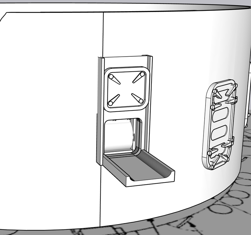
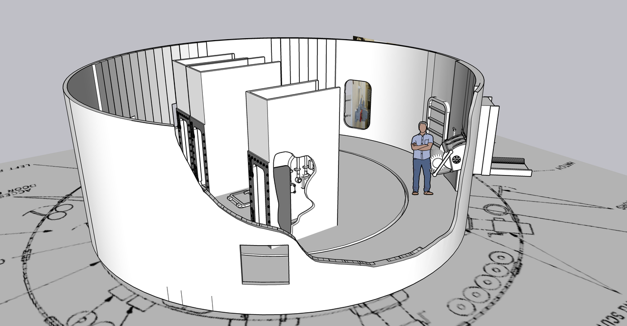
I finally got the powder trunks sized reasonably close. They were too big and when I added the various decks, if I moved them forward, they would stick out through the wall and if I moved them back, they would stick out there. They were interfering with equipment that had to be placed in the various decks. It took hours of trial and error to keep changing their size (and angle) to get them to work. They don’t just go straight down from the gun house to the powder flat. They proceed down in an angular path that changes as it goes down.

Changing the size changed the opening in the various decks. SketchUp can be a complete pain in the butt. It has the nasty habit of closing opening in surfaces when you add a line that shouldn’t actually do that. And then you can’t seem to get the surface to open again. This gets exasperating and can eat up hours of fussing on what should be a simple task. I used the “Interact Faces” with the trunks and decks to have the surfaces in which I want the opening to be. The result is a bunch of rectangles that are shapes that should be actionable. So then one trunk’s rectangle works perfectly, but the other is still attached to the existing surface and no matter what I do, I can’t get it to behave separately. Often I mess with it so long that I screw up other aspects of the part that have to be redrawn.

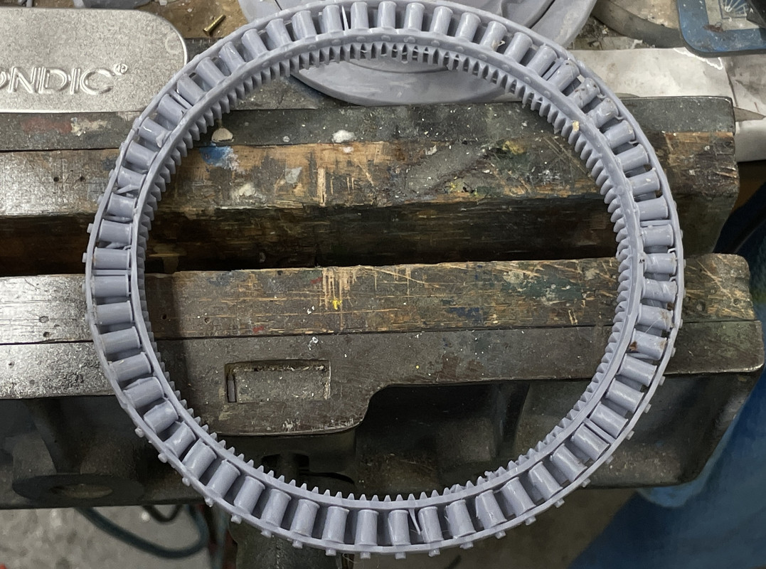
I had a couple of weird failures. The roller track assembly had some support failures that caused distortions, but it didn’t matter because I created the assembly with the wrong roller track. It should have been the lower, plain track. Instead, I combined the rollers with the track with the ring get, which BTW printed very nicely as a single piece, eliminating the out-of-round creation I made with the four-part gear.

Printing the rollers as a single part saved me a lot of very difficult work if I were to go with my original idea; assemble the roller assembly from separate rollers and pins, which I actually never figured out how I was going to.

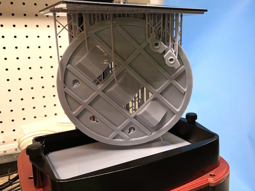
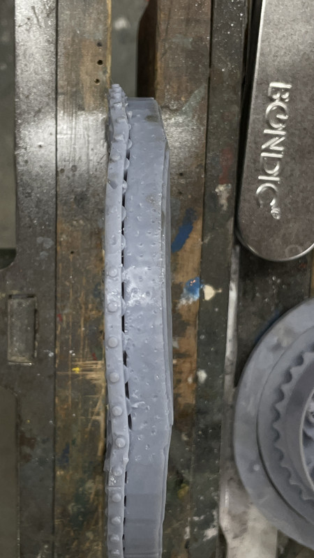
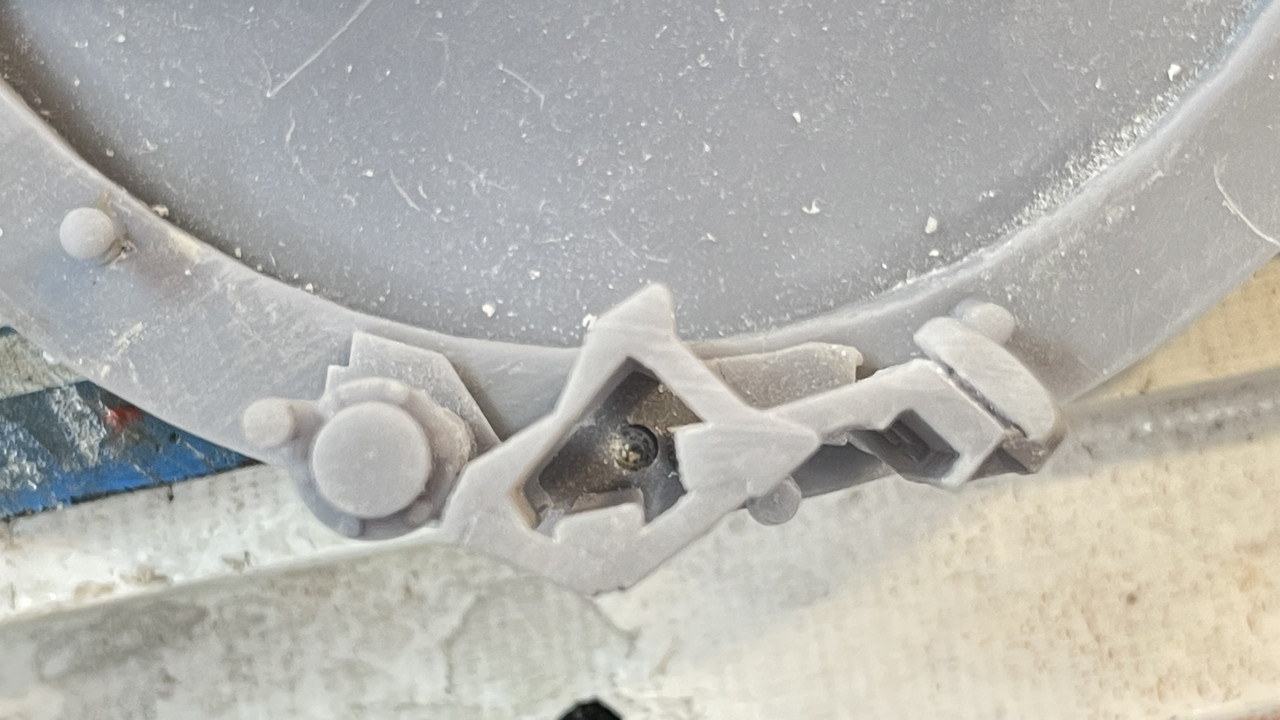
This side image shows the distortion from the localized support failure.

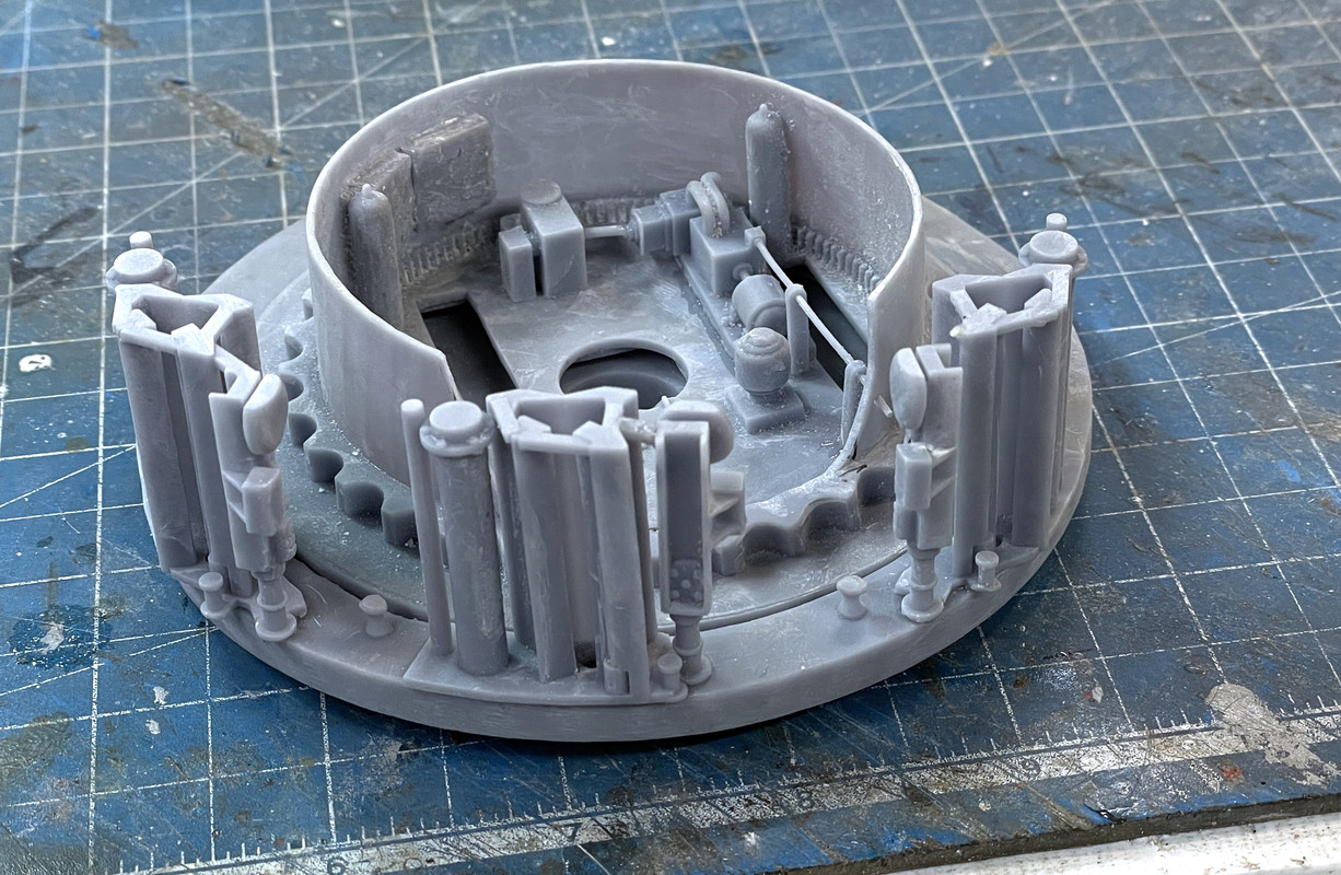
I’ve re-drawn this assembly with the correct race and set it up a bit differently to prevent the support weakness.

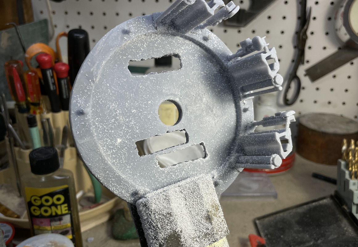
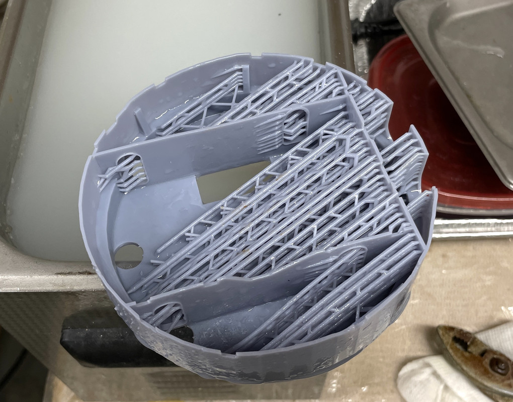
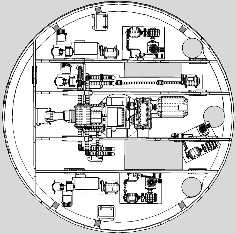
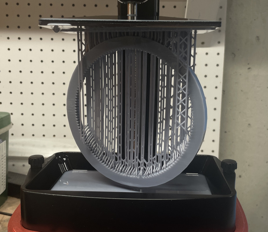
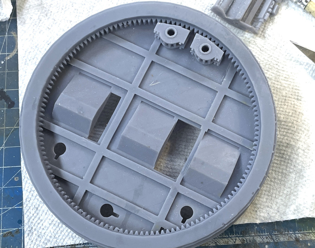
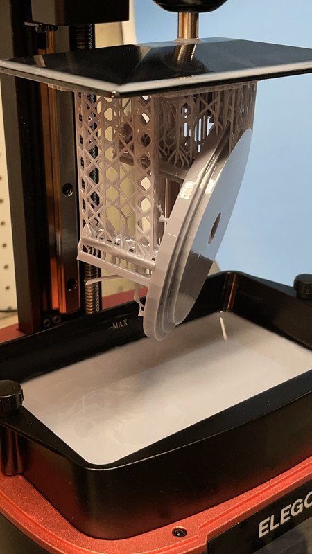
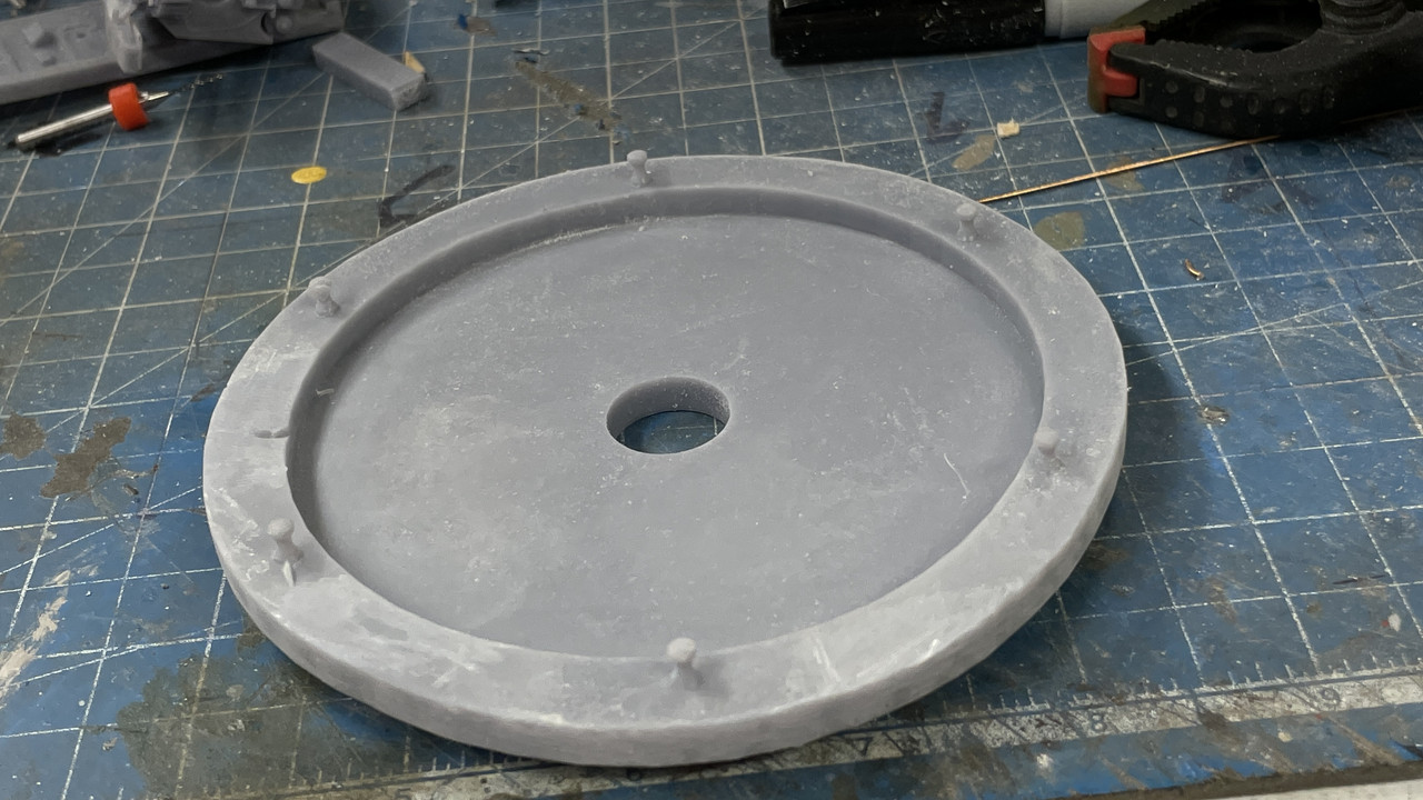
The diamter of the parts for this project are literally at the limits of my Mars 3 printer. This is the ring gear when it finished. If I tilted it or rotated it in either direction some portion of the part was out of the print range. It’s lucky I’m doing 1:72. Any larger scale would not work. There are bigger LCD printers on the market now, so if there’s a 1:48 in the future, it would require a completely revamped shop situation.

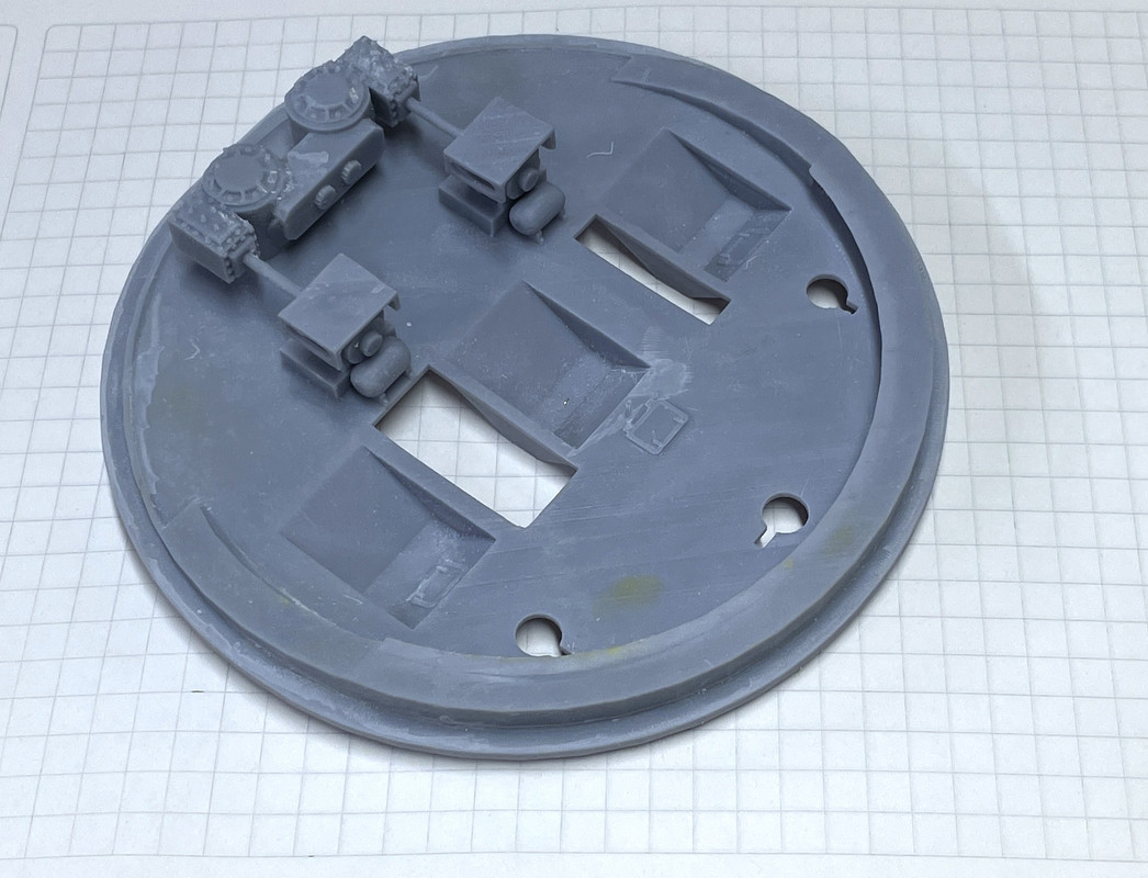
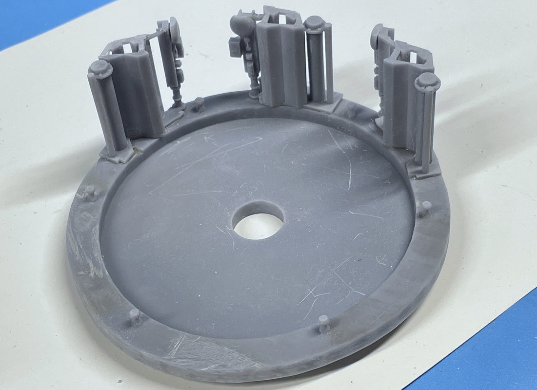
Here’s the gear flopped on top of the pan deck base with it’s pinion gears on the bottom.

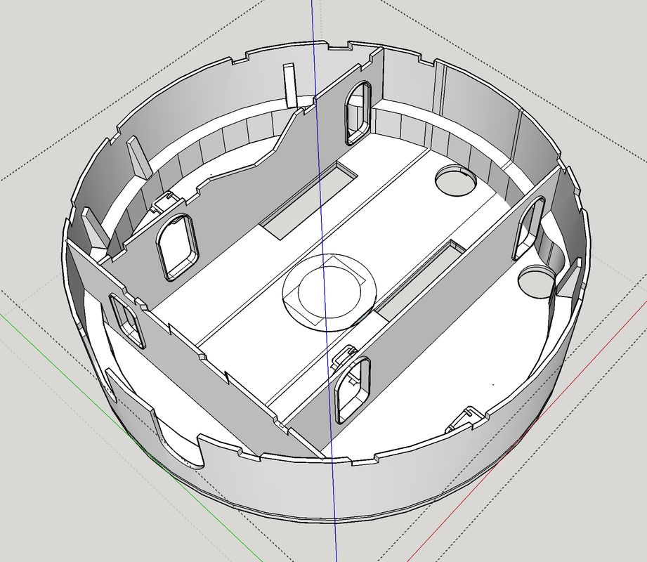
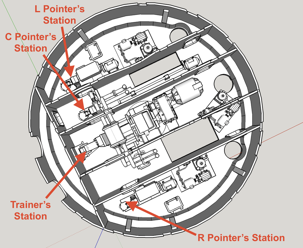
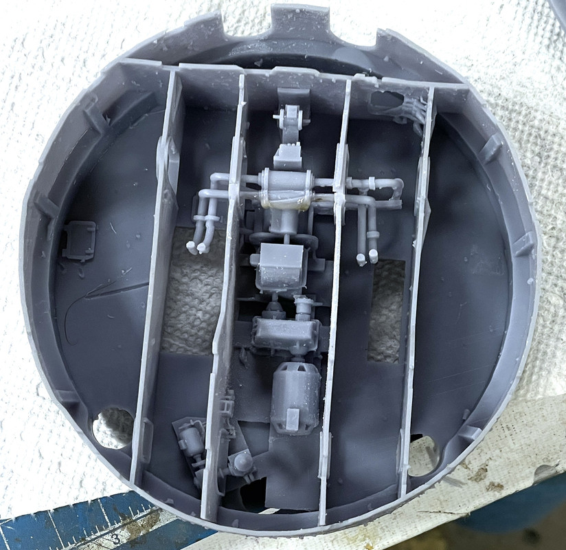
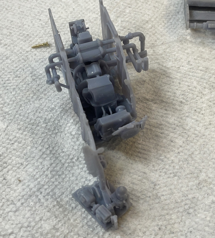
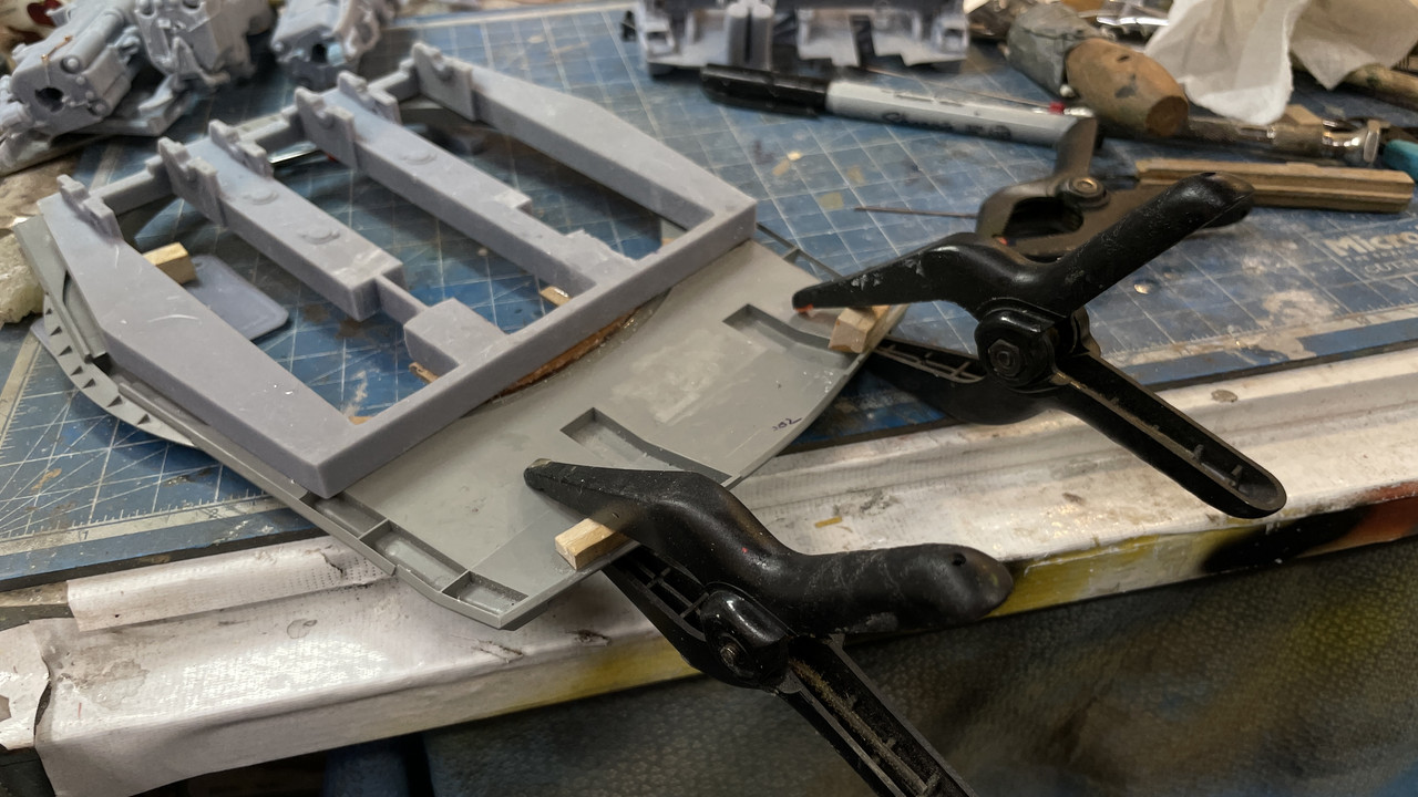
A complicated print was the machinery on the electric deck AND the center two partitions, the training machinery and the angled projectile hoist pump assembly for the middle gun. The machinery itself almost printed… the partition walls failed and distorted terribly. The little separate machines (other pump systems and two of the Pointers stations) printed quite nicely and are usable.

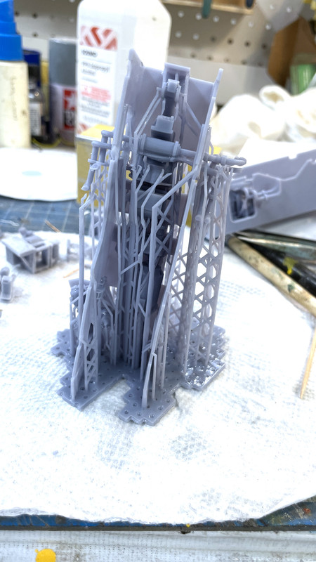
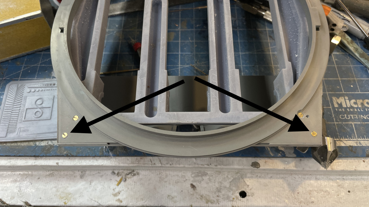
Here’s a down-the-line view of the partition assembly. You might notice that the big 300hp motor that supposed to be in the foreground, didn’t print either. Two factors were at play. I didn’t use enough heavy supports and relied on the light ones to do more work holding it all up too much. And the partition walls themselves were too frail at the tiny portion over the too passageways on the foreground end. The walls themselves couldn’t withstand the pulling forces in play in this printing process. I redesigned the walls at those weak points and used more heavy supports especially on the bottom end of the big motor. In the foreground is that smaller pump unit. While it was somewhat usable, I scrapped it along with the rest.

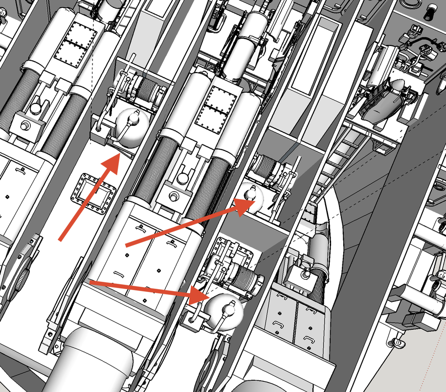
The side view shows the massive distortion and the break at the passageway.

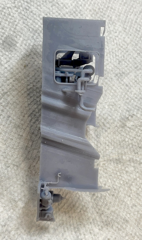
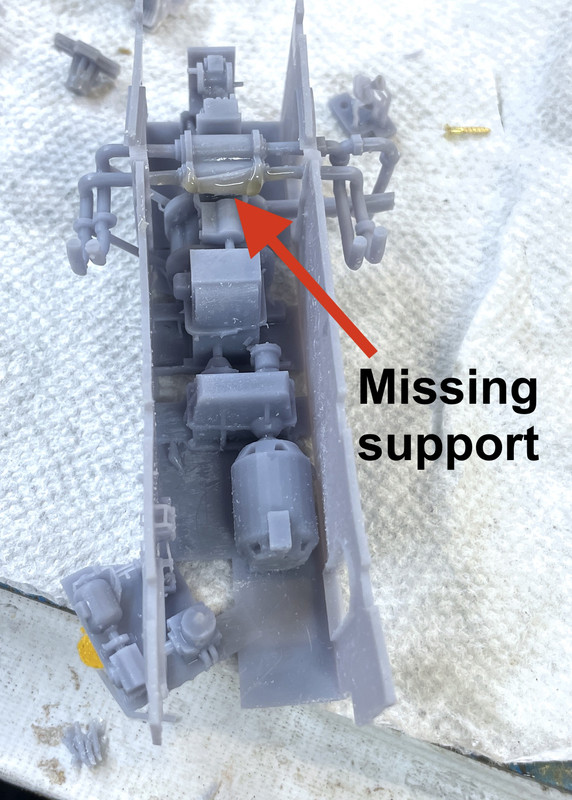
It’s on the printer now and will be done sometime in the middle of the night. I’ll know tomorrow if my solution was the correct one. You can see some of the fine piping didn’t make it through the support removal process. I also lost some seats so I’m printing a whole bunch of them with the job that’s now on the machine so I’ll be able to replace them. They’re very delicate.

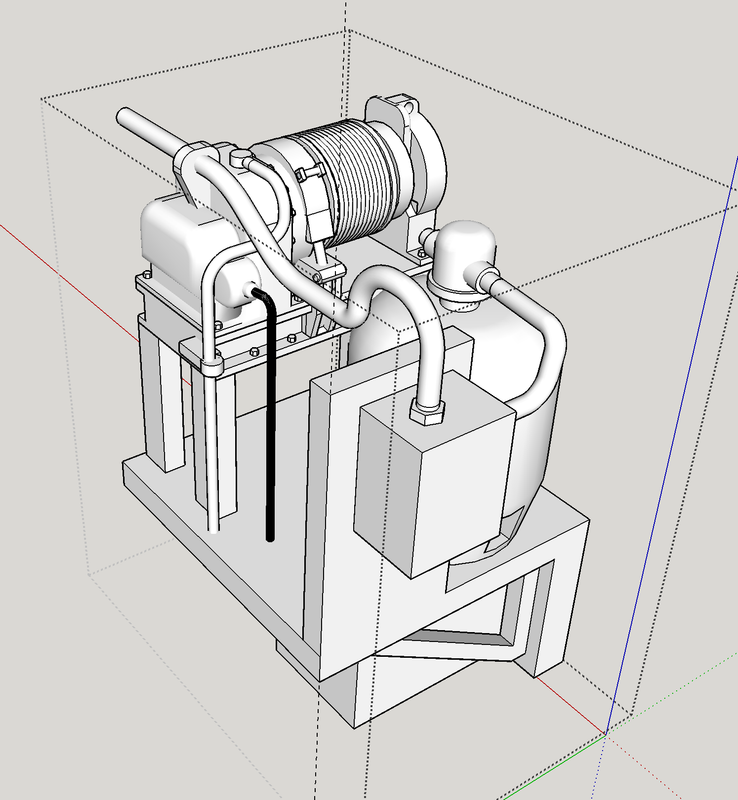
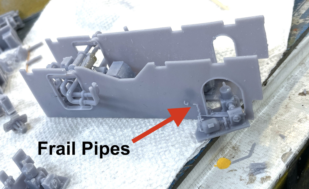
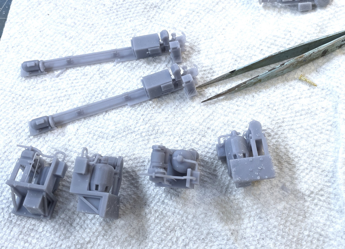
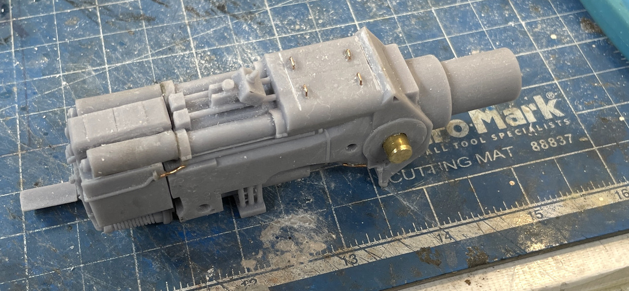
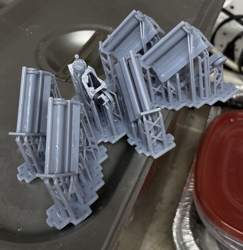
I printed another batch of machiness. This included the center pointer’s station with it’s long drive shaft separating the motor from the hydraulics. This is necessitated becuase the port side powder trunk passes through that area. I also printed the re-designed hoist machines complete with their motors, pumps and pipping. I’m finding, that while beautiful, using scale 1 to 2 inch piping is almost too small to work in 1:72 printing.

I had two failures in this print, again due to supports that were too frail. I need two of one hand and one of the other for the hoist machines. I made six, but the two I scrapped were both of the opposite hand. So I have four of the same orientation. I’ll pick the best two.

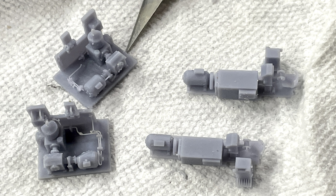
Here are the hoist machines and the center pointers system. You wanted something to show scale. That’s my finest point tweezers in the image. All four of those hoist systems are the same orientation.

Wish me luck. I have to print and new electric deck, new pan deck base, two projectile flat inners and one outer, the powder trunks (multi-part due to their length) and the hoist operator’s stations.

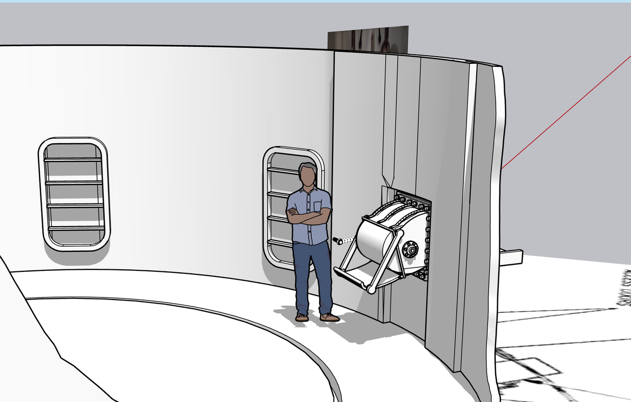
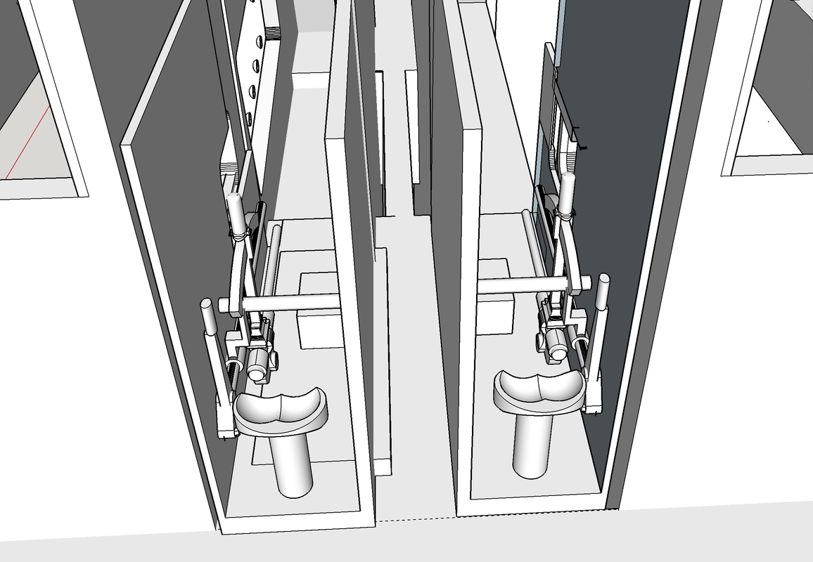
Here’s the hoist station. It is not completely accurate. The operating handle isn’t right, and hopefully, I’ll be able to view inside that compartment when I take the tour.

8 Likes

Exactly! :smiling_face:

I use this same criteria whenever I approach a model build. Surely if the details aren’t available in the specialist library all us modellers seem to possess, then what chance does Joe Average have of knowing if what we’ve built is correct or what it should look like :+1::cowboy_hat_face:

It has to look “right”. All the rest is just for the rivet counters. If you’re entering a model show then you’ll have an audience that may or may not “really” know what it’s supposed to look like, but in a mueseum ship with thousands of “normal” folks going through only a very few will recognize any discrepancy.

Case in point is the model work for the movie industry. As I noted earlier, “Under Siege” showed the “inside” of a 16" turret that looked great on the screen, but was a complete fake that could not exist in the real world. It was built for better camera angles and lighting showing the whole deal, whereas in the real ship the gun compartments are very tight and would film terribly.

Woke up this morning still noodling how to display the innerds. I even thought of printing some of the decks/partitions in transparent resin, but optically I don’t think it will work. I’m going to print a test just for fun to see what’s what.

My concern is the floor of the pan deck and the electric deck. The electric deck has so much going on inside that no one ever sees. It would be a real shame if I can’t find a way to expose it, espectially since the machines are coming out so nicely.

The partitiion print is finished and hanging on the machine and first looks show it to be completely successful. Part of the joy of this hobby is having a problem, analyzing it and fixing it. I’ll report on it later today.

I spent the first 52 years of my modeling basically building kits with instructions doing an occassional scratch-built enhancement. I started scratch-building in my 60s and am very happy I did. It opened up a whole new experience. More frustrating… yes… but far more rewarding.

2 Likes

I find scratch building enjoyable also, nothing beats a cheap upgrade or repair to a kit.

Mark :beer:

Thanks for the nice words!

The center section print(s) were 95% successful and I’m using it. I made two so I can choose the best. Here’s the support scheme. As comprehensive as it appears, I missed one surface that failed to form: one of the lobes of the hydraulic manifold. I am in the process of sort-of restoring it with Bondic. It’s buried in the assembly and will not be visible regardless of how I cut away the walls. You see the missing lower part of the cylinder. The slicer shows susceptible failure areas by highlighting them in red, but this one was hidden from any angle that I tried to view it.

Here’s the finished print cleaned, and post-hardened showing the Bondic rough filler. Some careful Dremel sculpting will make it presentable.

This section nestled up into the pan deck floor perfectly especially around all the stiffening ribs in the pan deck floor. By using one shape to cut into another in SketchUp, you get perfectly aligned and matched surfaces. This view also shows the manifold piping is non-aligned with the hydraulic training motors. I will remove the resin lines and pipe with solder wire or bent sprue of the correct diameter.

Viewed from the top you can see where the pipes should actually go.

This next view shows the fragility of the tiny piping that I drew. It’s a bit more than 1 scale in, but that’s only 0.014" in 1:72. I think 2" piping would work. Just becasue I can draw it doesn’t mean that it should be printed that way. BTW: I added stiffening ribs in the passageways on the left of this image. That added the stregth needed to keep the walls together in that very weak spot.

Meanwhile, I got a near perfect print of the entire electric deck. The revised support scheme did the trick and there were no collapsed or distorted areas. Here’s the forest of supports needed to print it. I had already removed the massive group of them holding the bottom to the printing raft. I couldn’t get it into the Ultrasonice Cleaner with the raft still attached.

Here it is de-suppoorted (word?) with the center section test fit before post-curing. After curing I remove all the nubs with the sanding tools. Semi-cured resin doesn’t sand well since it’s too soft and pliable. You can see the trainer’s station at the top of the center section. Those are the hand wheels that “supposedly” can manually crank around a 2,500 ton turret if the hydraulics failed. As I noted before, it must have been like Hell on earth sitting in that space surrounded by whining electrical and hydraulic machinery. I imagine being in the engine room of a diesel sub would be a similar experience.

With a successful electric deck print all the equipment for it printed, I’m ready to start painting and assembling it. I do see some interference with the center section of the projectile hoist trunk holes. I will open that up before moving along. It’s blocked by more false flooring on the center that I added to support the big motor. I will remove some of that.

I made a vertical screen print showing the equipment placement. I also made 1:1 scale prints of the six partitiion walls that extend from the gun house roof to the pan deck floor. Some of these will be cut from 0.040" styrene and others will be thin clear acrylic to be see thru.

The electric deck was a huge milestone! It was one of the aspects of this job that had me most concerned since I had no photos of anything taken directly in this space.

7 Likes

Amazing and HIGHLY motivational stuff!

I’m also very appreciative of how much of the 3D printing details you’ve been sharing. It’s always instructive to see examples of other support and printing setups.

You’re very welcome.

I haven’t been slacking. What I have been doing it re-drawing parts that needed fixing and working on the powder flat. The field trip is a week away and I was very pleased to find out by viewing the USS New Jersey videos produced by Ryan Szimanski, the Curator, that you don’t have to climb vertical ladders through very tiny floor hatches to see the lower turret levels. They installed real code-adhering stairways and cut openings in the side of the turret so you don’t have to get into it via the same route.

I was able to extract a lot of information from various videos to create the powder passing scuttles. Some had people in the pic so I was able to approximate scale. More troubling was the small chamber that the lower powder hoist operator works. I can’t print them with scale wall thicknesses and they’re now a big wide. I’m going to hold off printing them, although I did set them up for printing, until I visit the real powder flat and take some actual measurements. I’m bringing a measuring tape and a list of observations I want to make.

I’m printing the rotating powder cylinder like I’m doing with the projectile flats, with the cutaway portion as part of the print itself instead of cutting and grinding away on the finished part. It will be a much smoother cut. I’m also planning on printing the hoist operators booth cutaway so you can see the controls within.

Here’s the powder scuttle interior. There are two sets of these. One passing powder bags from the magazine to the annular space, and directly across from the outlet is another scuttle that passes the bags to the inner cylinder. All of these parts are non-rotating. The inner circle in this cylinder spins with the turret. The figure is standing on the stationary part.

Here’s the input side of the scuttle. There’s a movable tray that lets the crew slide the bag from the first set to the second without having to lift the 110 pound bags. They do, however, have to manhandle the bags from the second scuttle to the loading trays (still need to draw) that sit in front of the powder hoist openings for each hoist.

And here’s a view of the turret progress so far. I’ve also drawn the water-tight doors (3) that lead into the inner cylinder and another set that open from the magazines into the annular spaces. On the right side of each booth will be the powder hoist trunks that penetrate all five decks to the gun house. The cylindrical wall is fairly thick here, but not barbette thick. This part of the turret is buried in the armored citadel. It must be strong enough to support the 2,500 ton rotating part of the turret and it terminates up two decks in a tapered cone that supports the lower roller race. Still left to draw are the aforementioned loading trays plus permanent and portable quenching tanks. These were used to douse any leaking powder bags so they wouldn’t cause a problem.

On Friday we’re leaving for our rescheduled trip back East to visit family and friends and the Big J tour. After we return in early July I won’t have any excuses for not finishing this project since I should have all my essential questions answers. One thing I’m going to spend a lot of time studying is the projectile hoists. I can’t really decipher exactly what I’m looking. Most pictures of it are from the sides and I can’t see it’s proper width, or whether it has three or four main legs.

7 Likes

Wow… I know that all of this naval architecture was evolutionary, so these designs were not just pulled out of thin air. They’re the pinnacle of centuries of warship design. Still, the complexity of these structures is astounding.

As always, thanks for taking the time and effort to share your work with us. It’s educational on several fronts!

1 Like

Considering that the total rotating mass of one of those turrets was around 1700 tonnes.
A Farragut destroyer was almost the same weight so those turrets could be seen as three
destroyers …
Note that it’s only the rotating mass, there was a lot of other weights that were not part of the
rotating mass …

1 Like

I’ve been given the number of 2,500 tons, so that’s even more than an entire destroyer. Add to that the hundreds of rounds at an average of 1 ton each… yup. it’s pretty awesome. I’ve been told that one rotation of the manual handwheel at the trainer’s station on the electric deck would equal 2° of turret movement. I find even that number large considering the gear reduction needed to turn the machines that turn the pinions. With that it would be 45 turns of the handwheel to rotate 90 degrees. I’ve also heard that you really couldn’t move it manually like that. I will find out next week.

1 Like

Probably some servo mechanism involved.
I have heard 2500 tons as well but I couldn’t find it so I went with the numbers I was reasonably certain about.
A Yamato turret was at least 2500 tons …