Regarding the tire questions it may be that the rigidity of the sidewalls is such that it collapses a bit around the contact patch and allows for greater contact area when the bike is not leaning. Just a possibility …
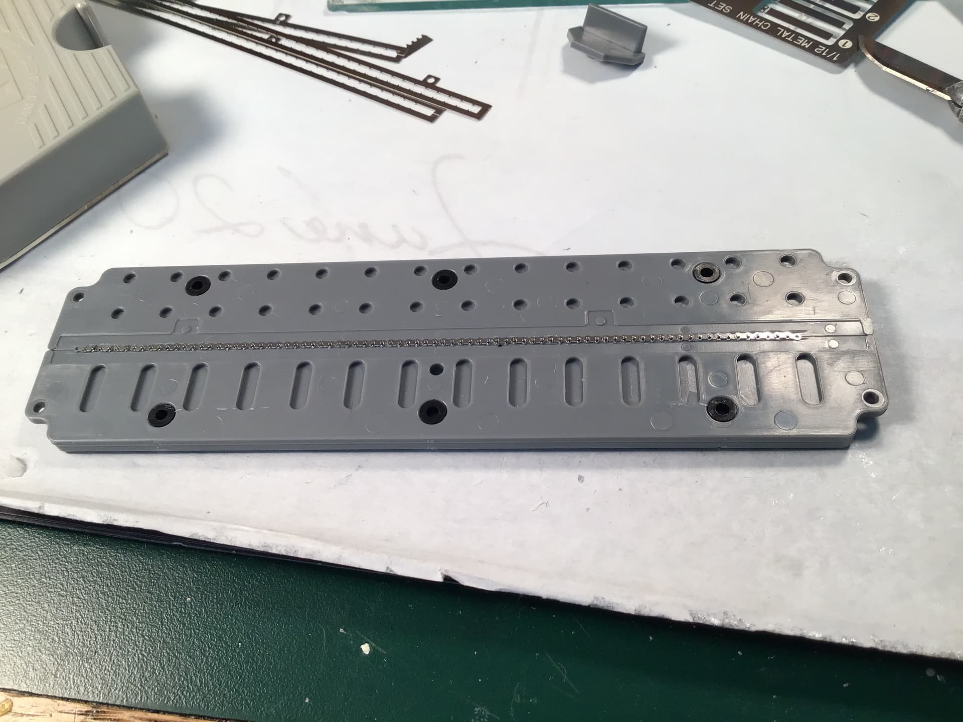
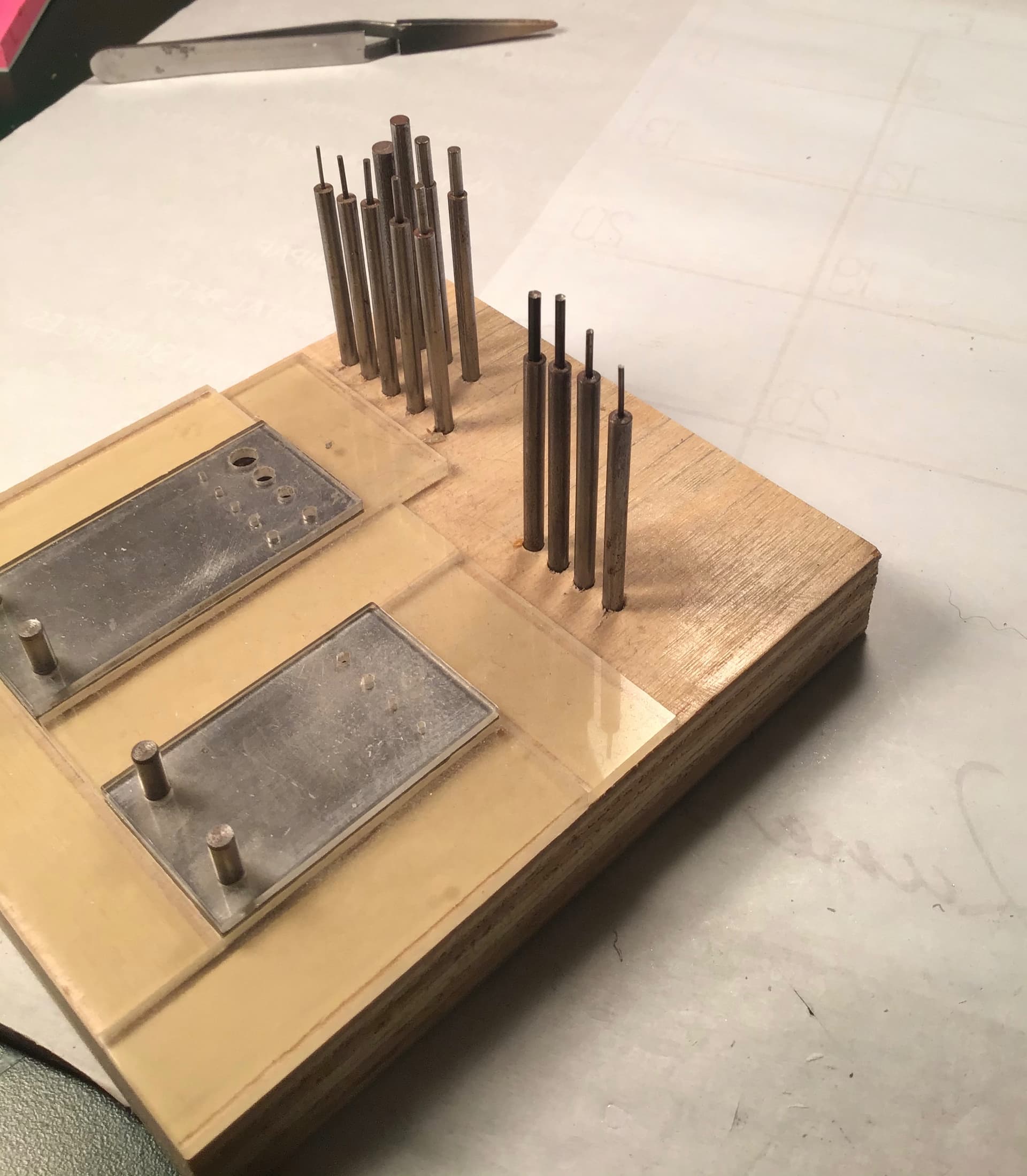
In the way of a more direct and accurate answer to Michael’s (cosimodo ) question earlier regarding photo etch for this kit here is a photo of what comes with the base kit…
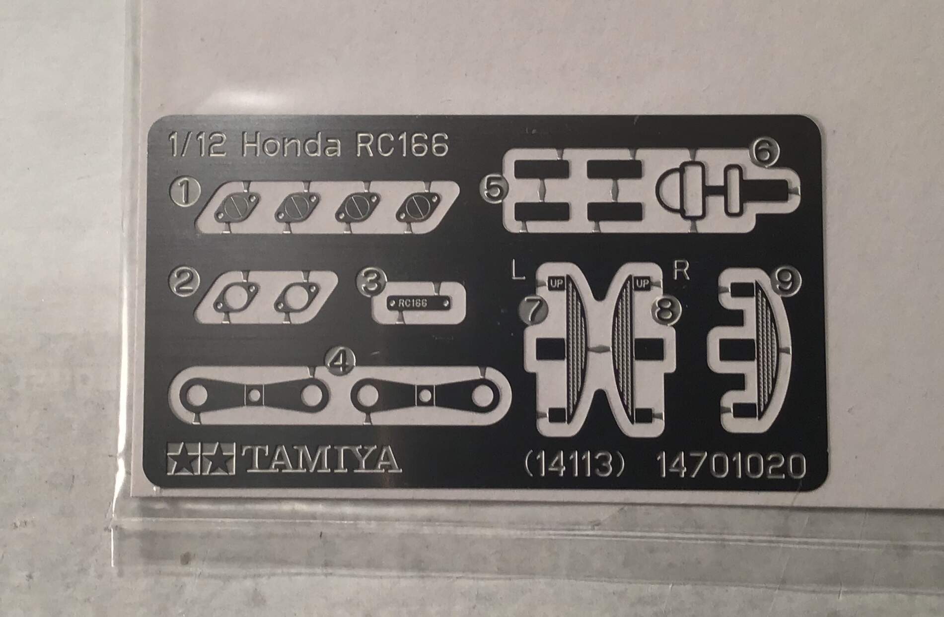
- and
- reinforcement plates at fairing attachment sites.
- Data plate for frame gusset
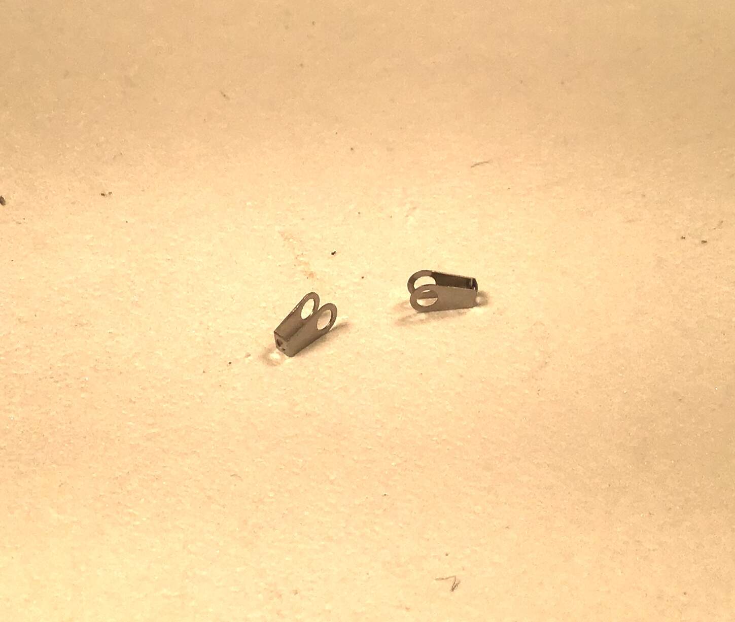
- final drive chain adjusters
- plates for magnetic attachment of various panels
on fairing - fuel tank hold down strap
- , 8) and 9) screens for drum brake air scoops.
3 Likes
Richard,
Interesting theory on the tire profile.
joel
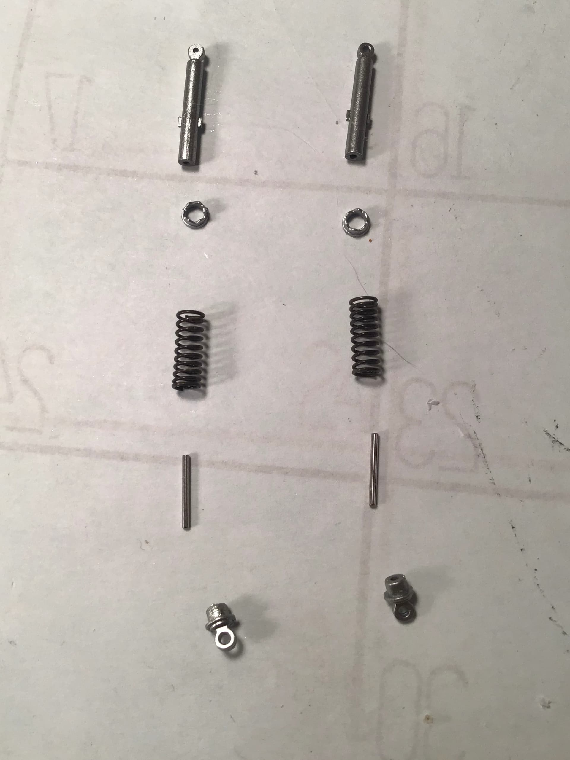
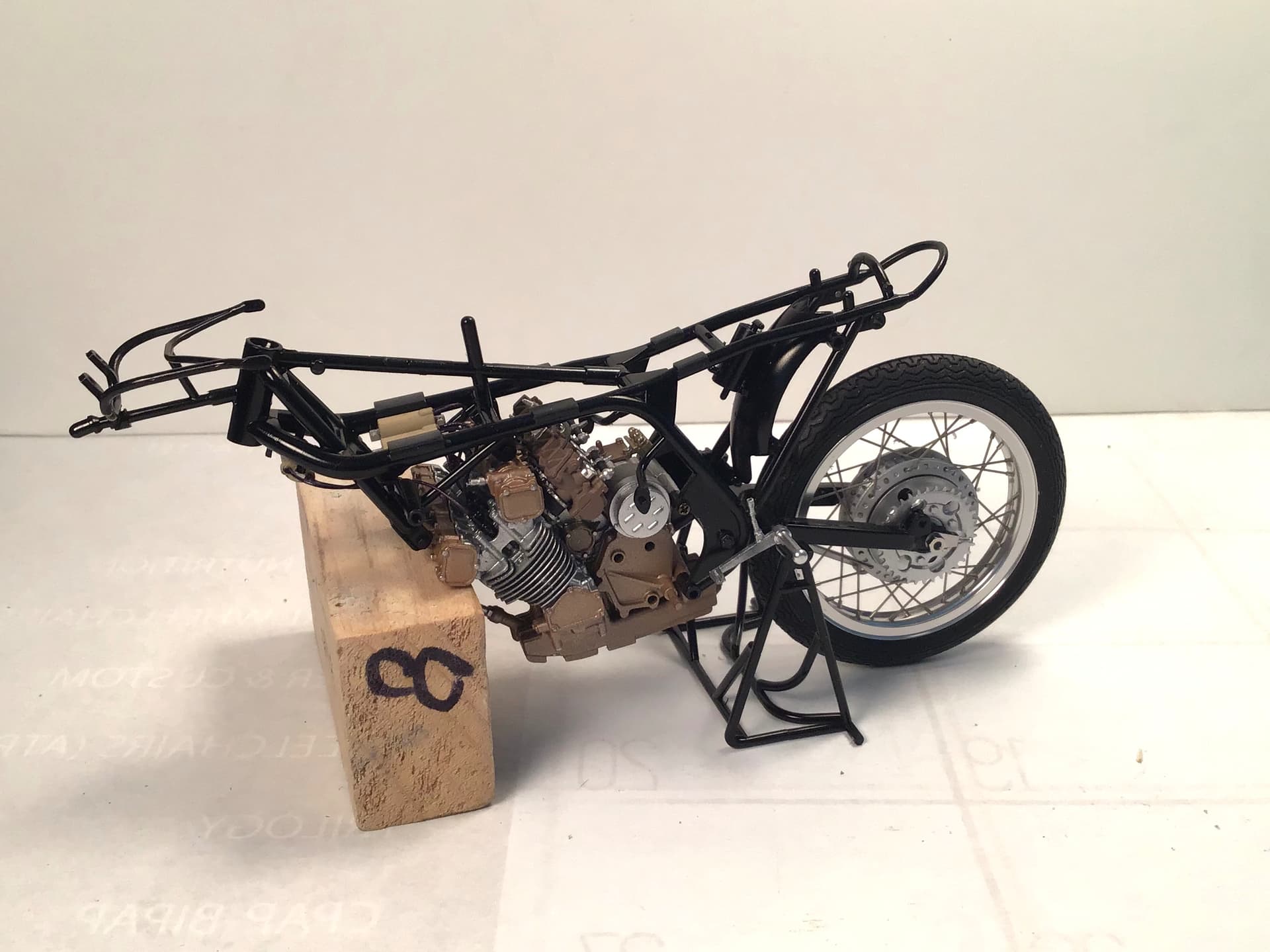
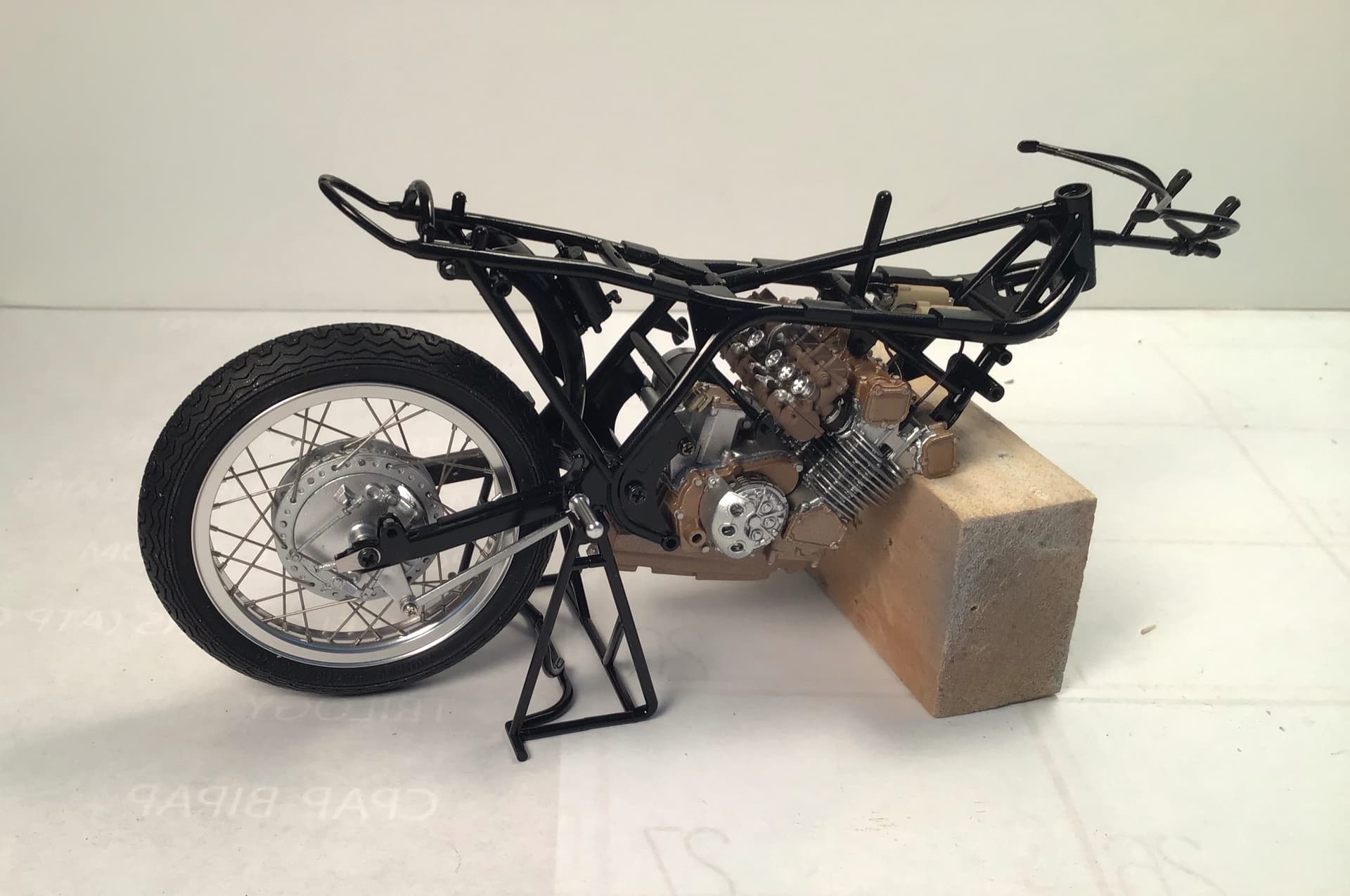
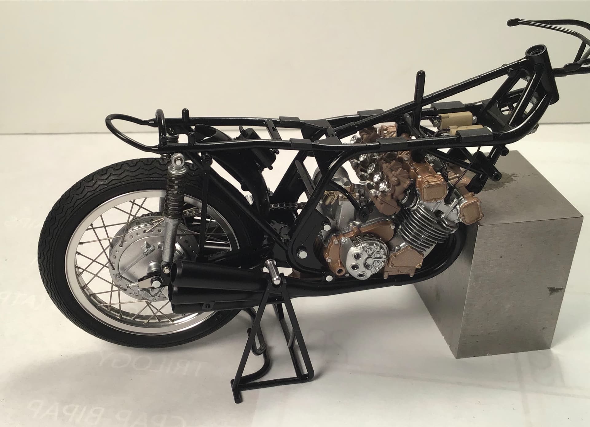
Progress on the back end …
Rear shock components…
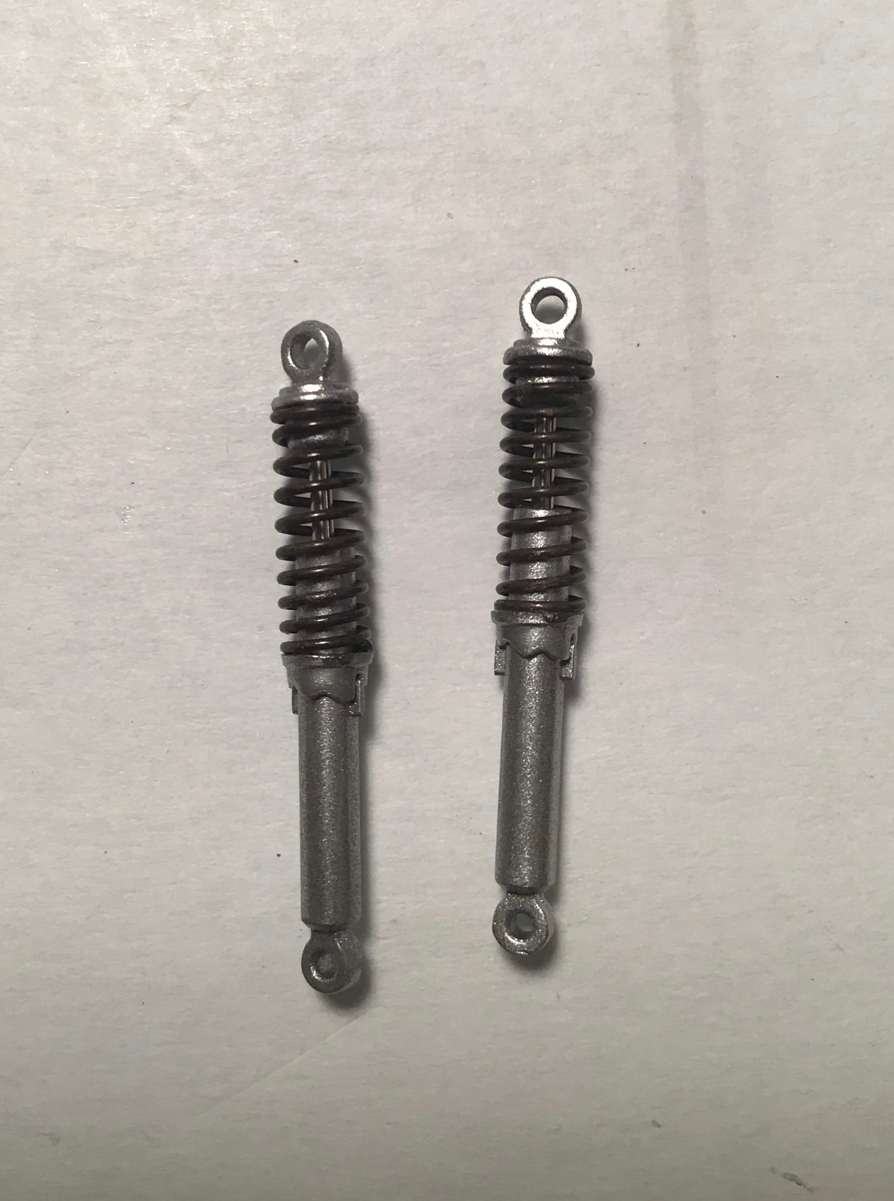
…and the shocks assembled…
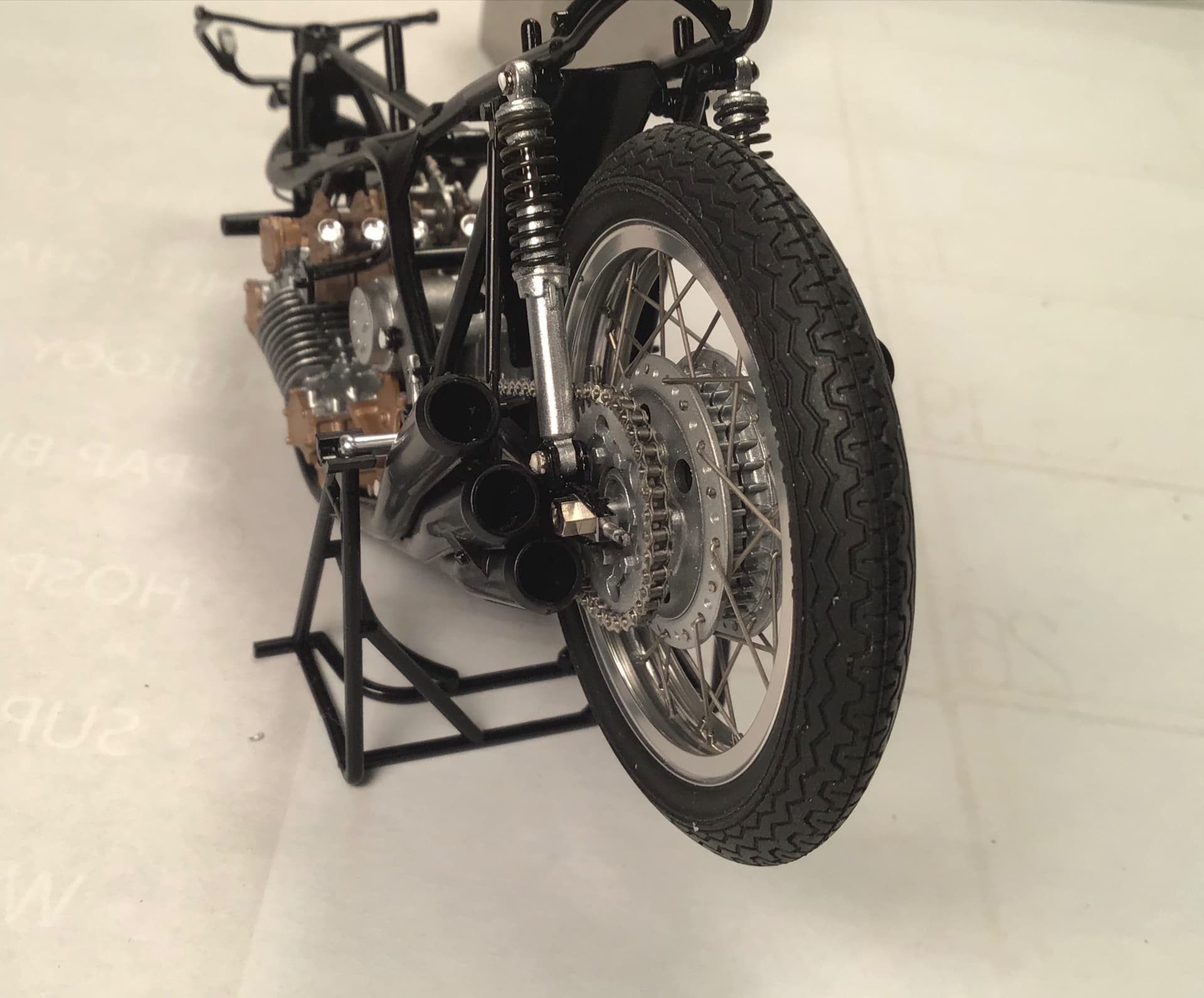
Rear brake plate & air scoop…
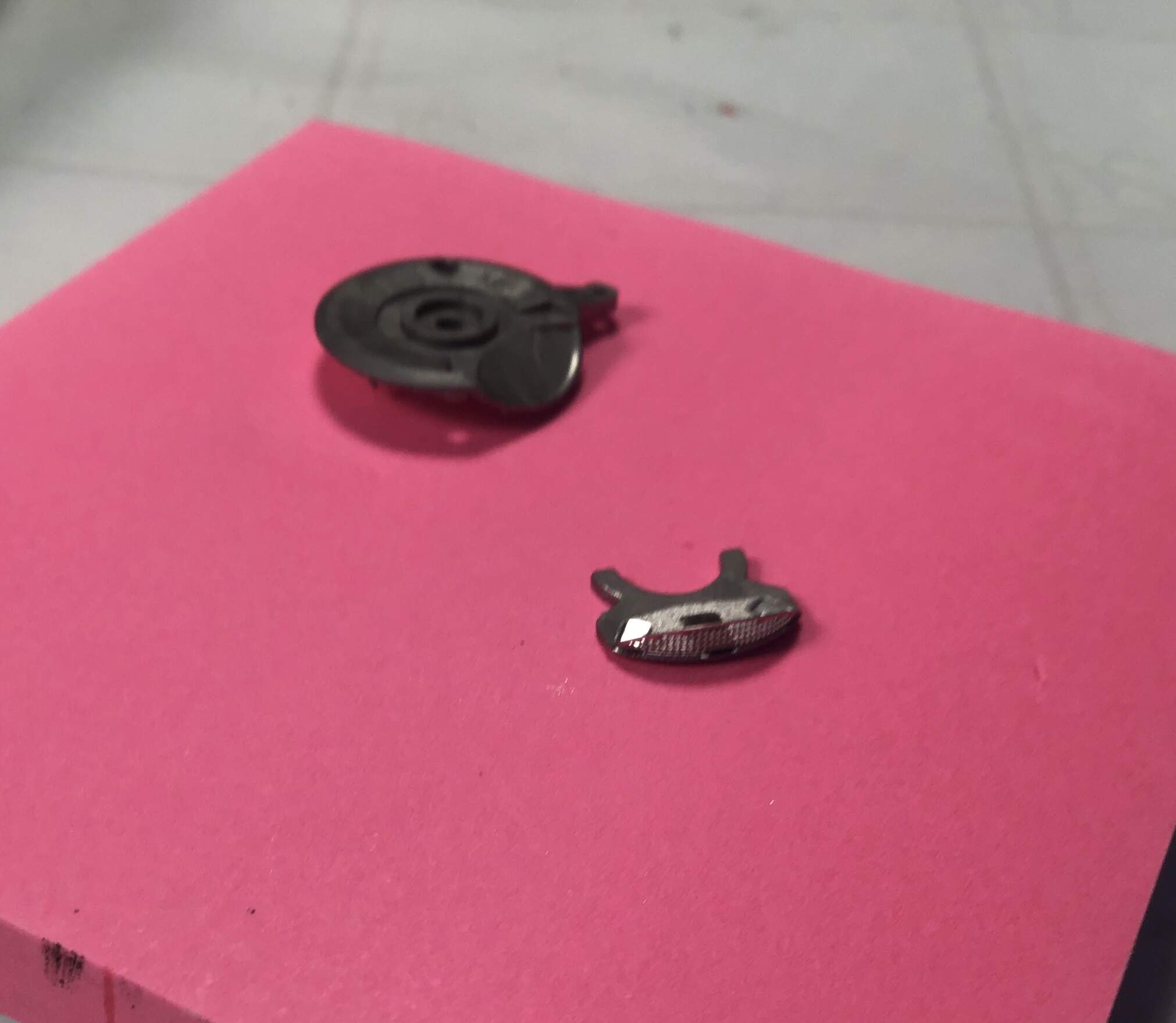
Completed brake plate and final drive sprocket - Tamiya even included the Cush drive between the sprocket and the hub …
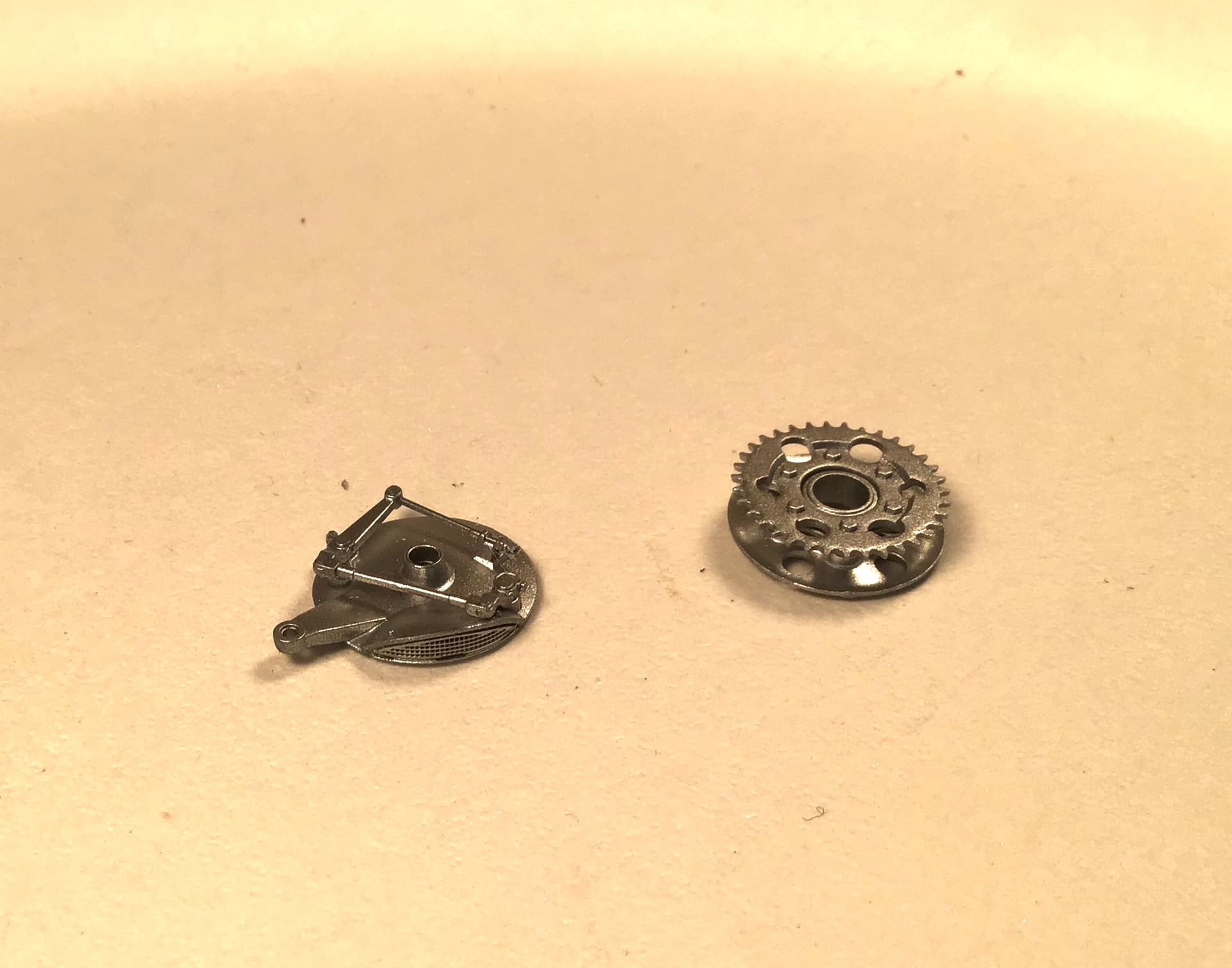
Final drive chain adjusters folded up from PE…
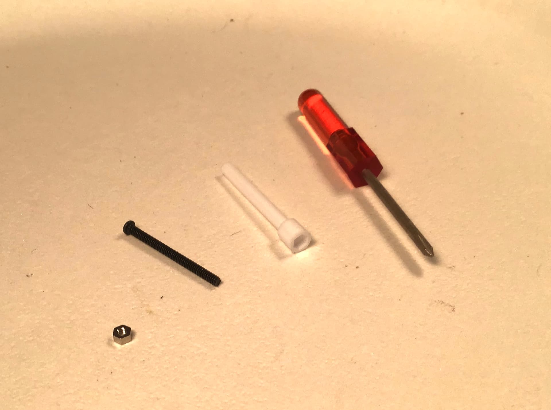
Tamiya includes a tiny Phillips head ( or it may be JIS) screwdriver and socket for the screws and nuts in the kit … in this case they make up the rear axle …
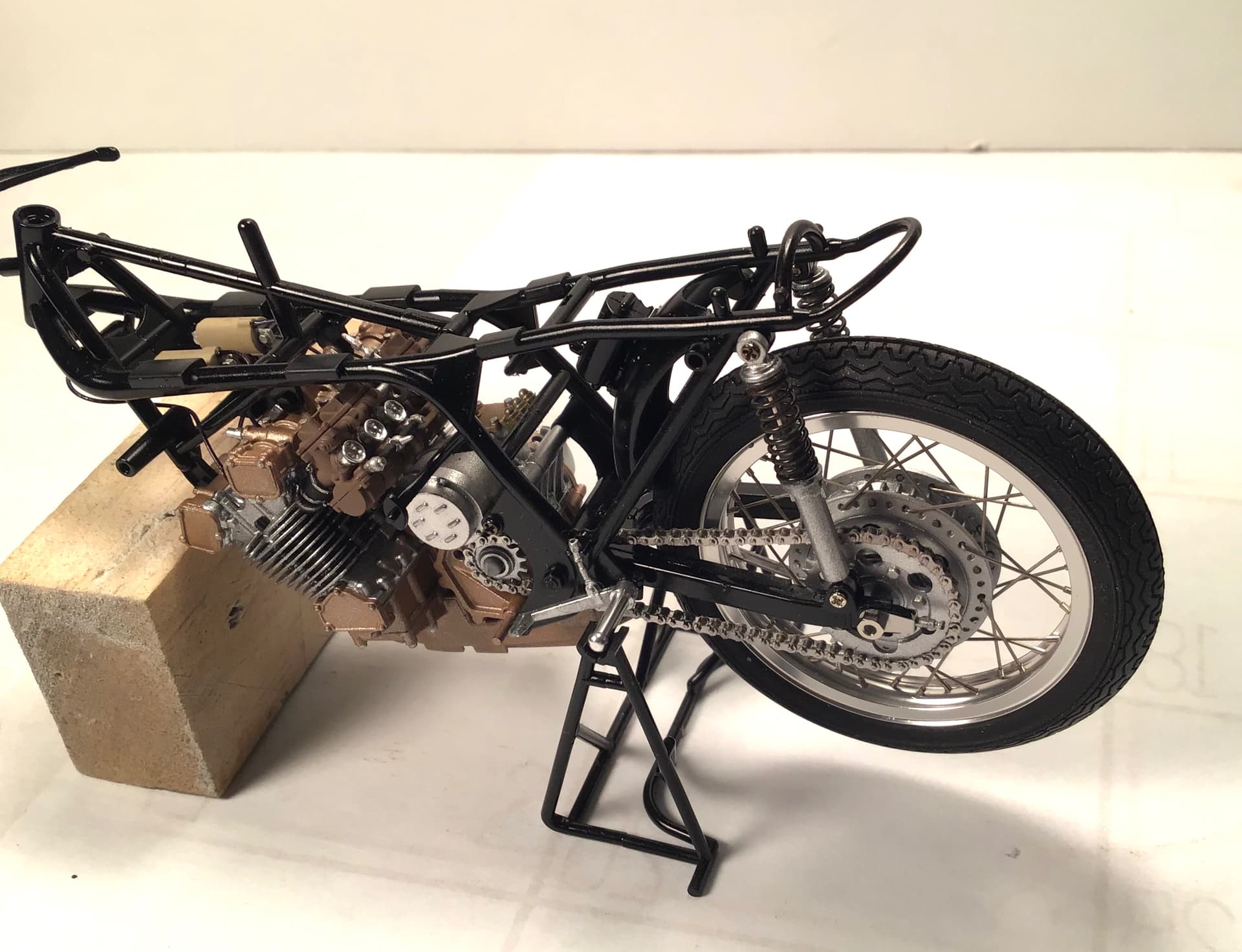
Lastly the rear wheel and swing arm installed.
Although they are ready I am going to leave the shocks off for now until I have the PE chain built up in case I need to remove rear wheel assembly to install chain.
Thanks for looking and as always all comments/questions welcomed.
Cheers - RT
5 Likes
Richard,
Outstanding progress and equally outstanding craftmanship on every facet of the build to date. The rear wheel swing arm with the rear wheel temp installed just makes your build look even more the equal to the real deal.
Boy do those shocks, brake plates, and Crush drive (?) look good. Between your skills and Tamiya’s engineering, I’m just amazed at the level of realism the RC 166 is achieving.
joel
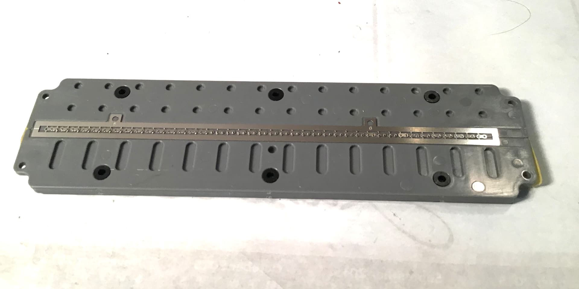
I’ve begun work on the photo etch chain .
Here’s what you get…
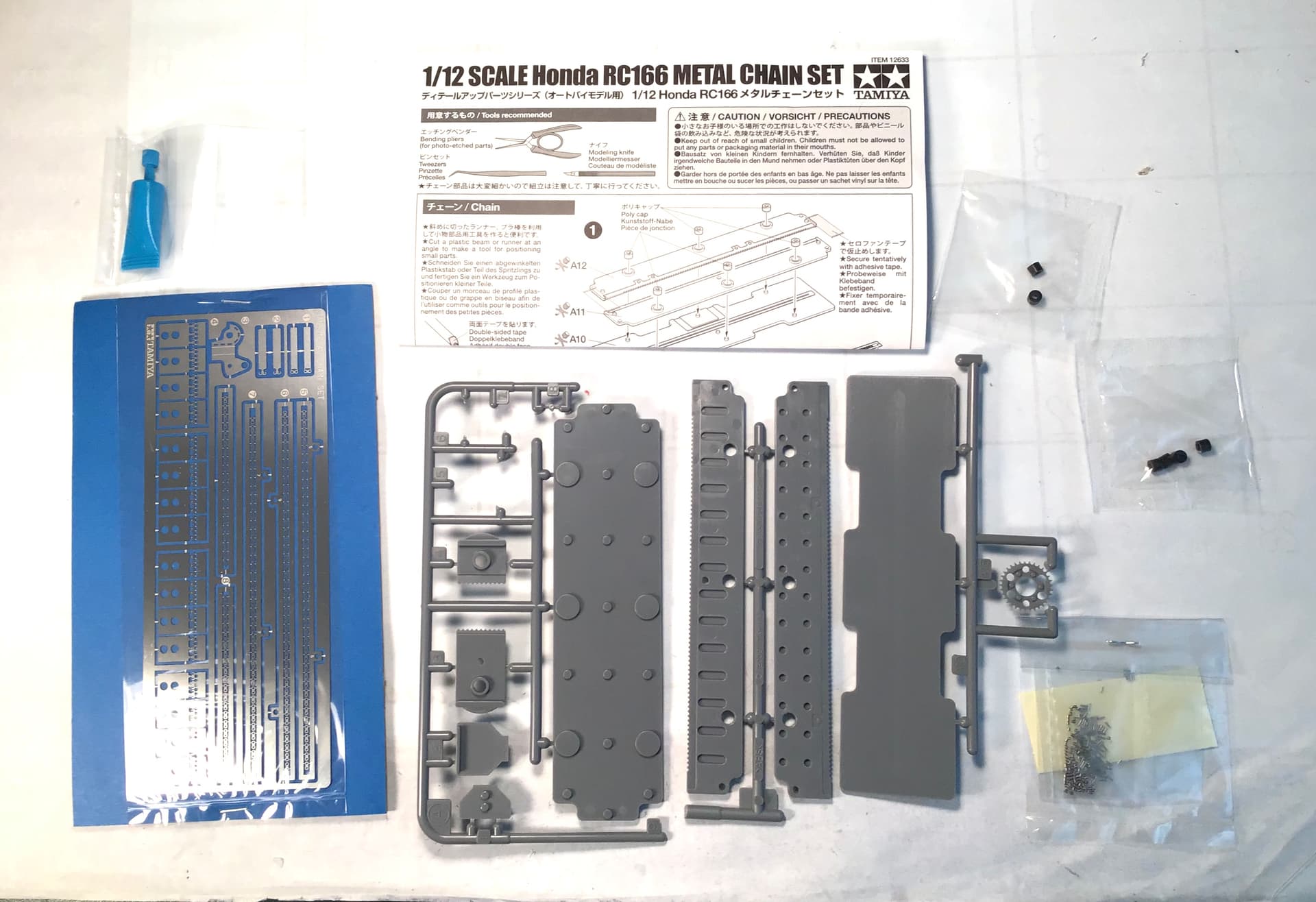
The PE links and chain guard for gearbox sprocket ,
a small tube of grease if you want to actually spin the drive train, instructions , plastic jig components,
Poly caps for jig , two rear wheel sprockets to replace the base kit sprocket that has a molded chain ( don’t know why two ) and a bag of miniature rollers and pins and some double sided tape.

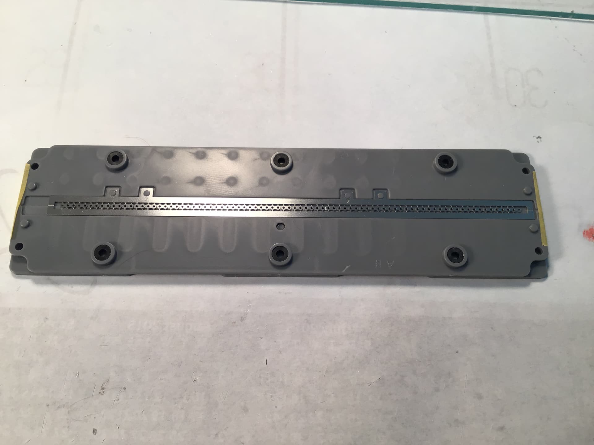
The instructions …
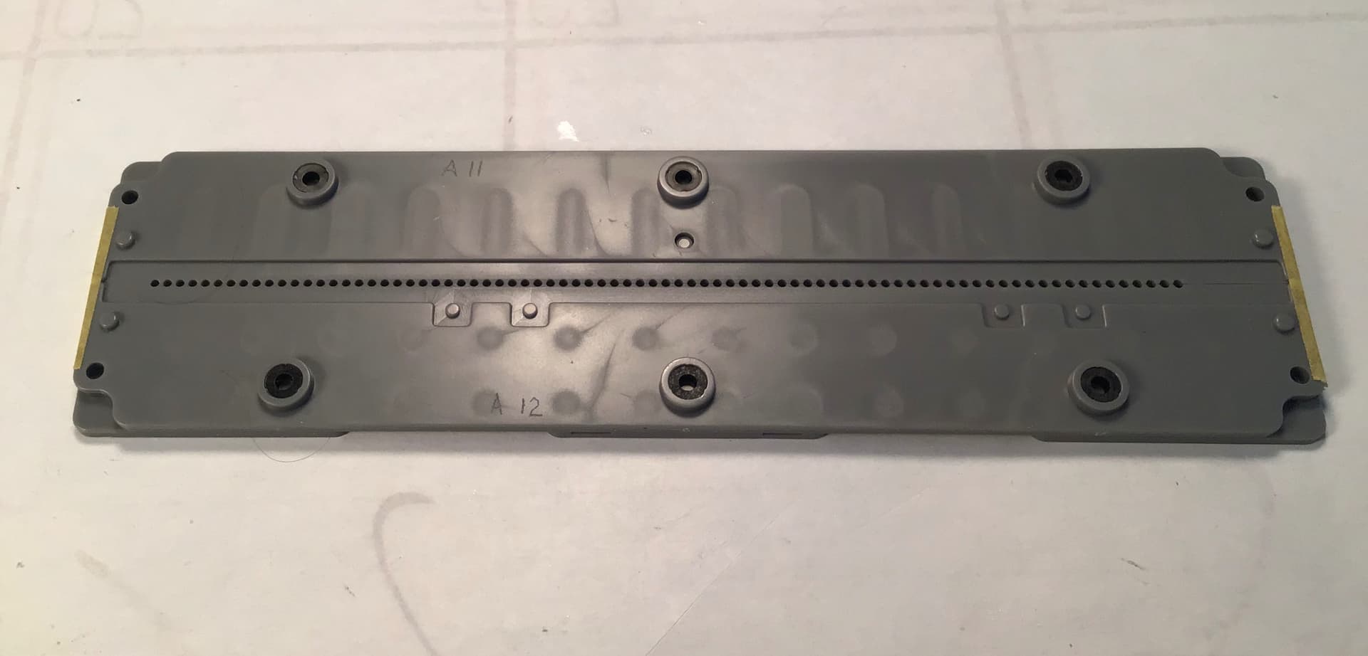
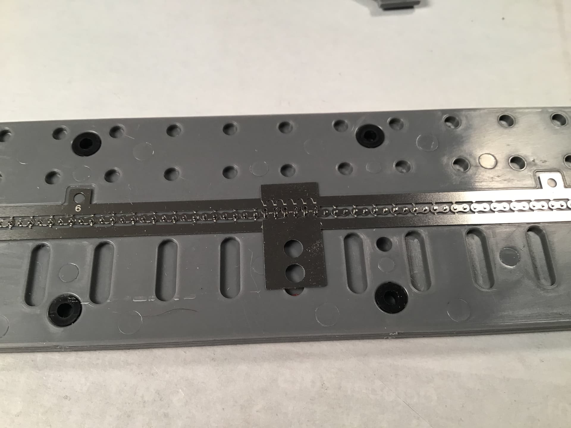
The jig set for first step - insertion of 80 rollers .
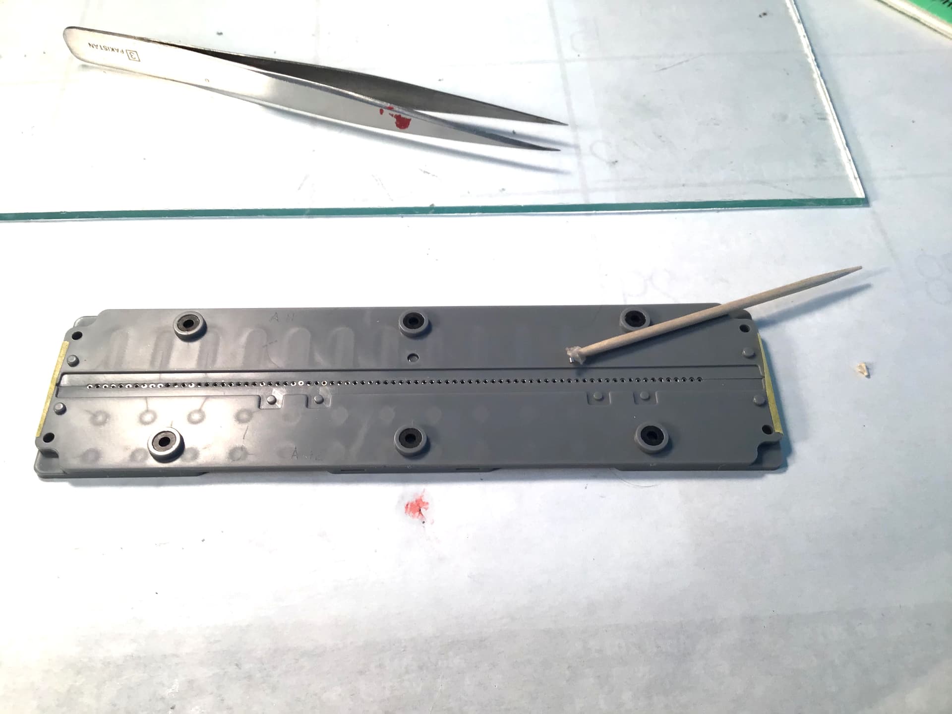
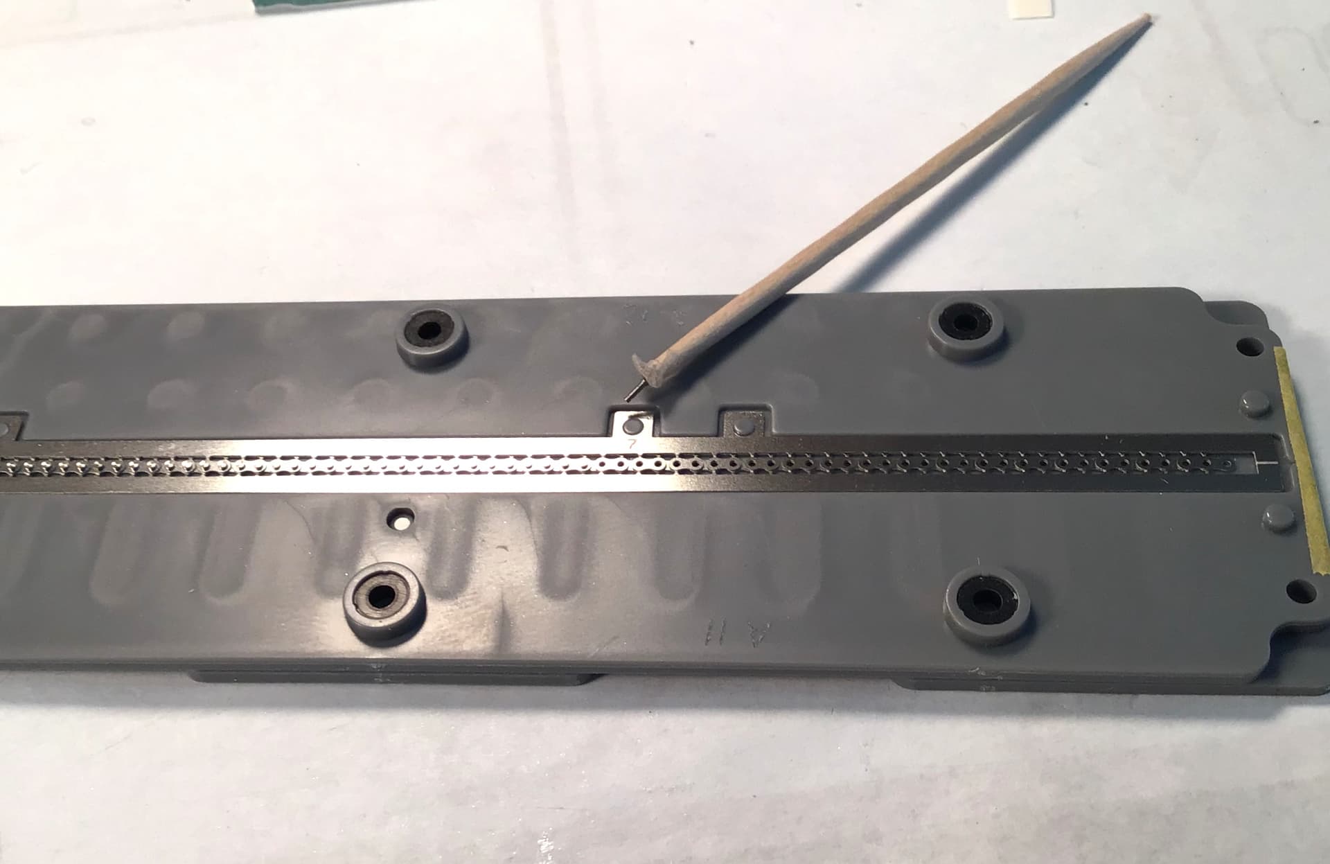
Rollers being inserted . At Tamiya’s suggestion you cut a toothpick or piece of sprue at a slight angle and place some double sided tape around the end to handle tiny parts . As the metal parts are magnetized some what my tweezers ( supposed to be non magnetic but they are not) the wooden toothpick is the way to go.
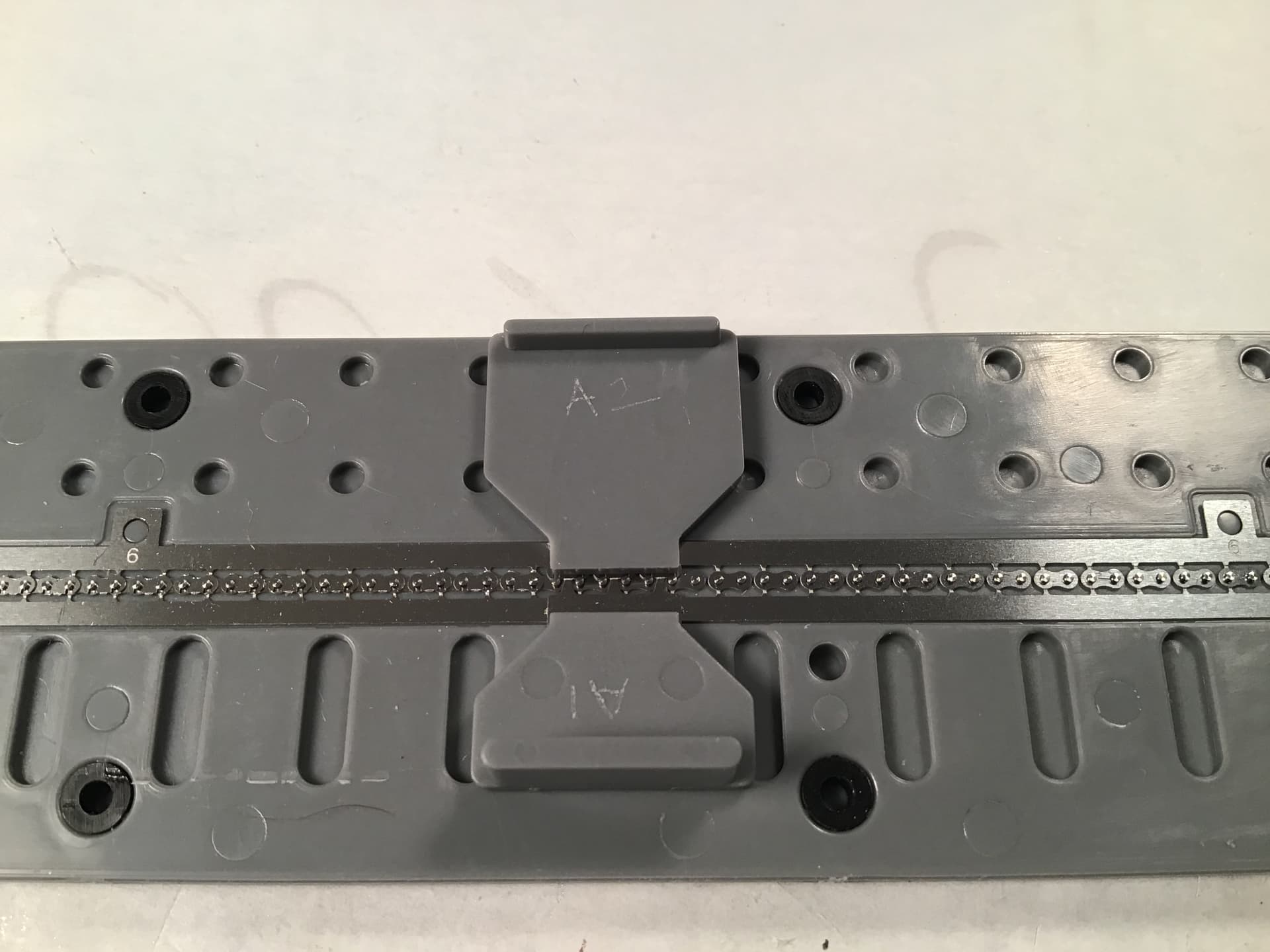
First layer of PE links in jig …
and the second layer .
Pins being inserted- 78 of them.
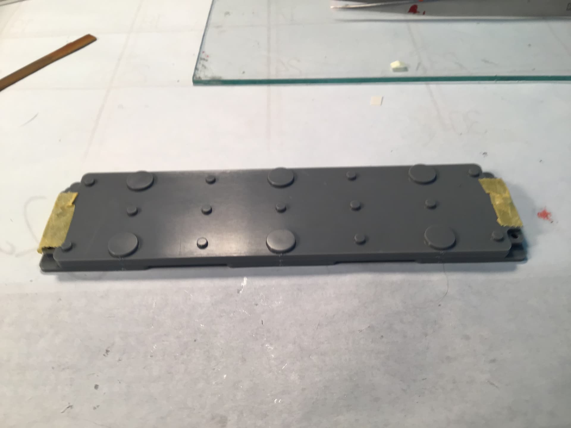
and the lid in place to hold all together.
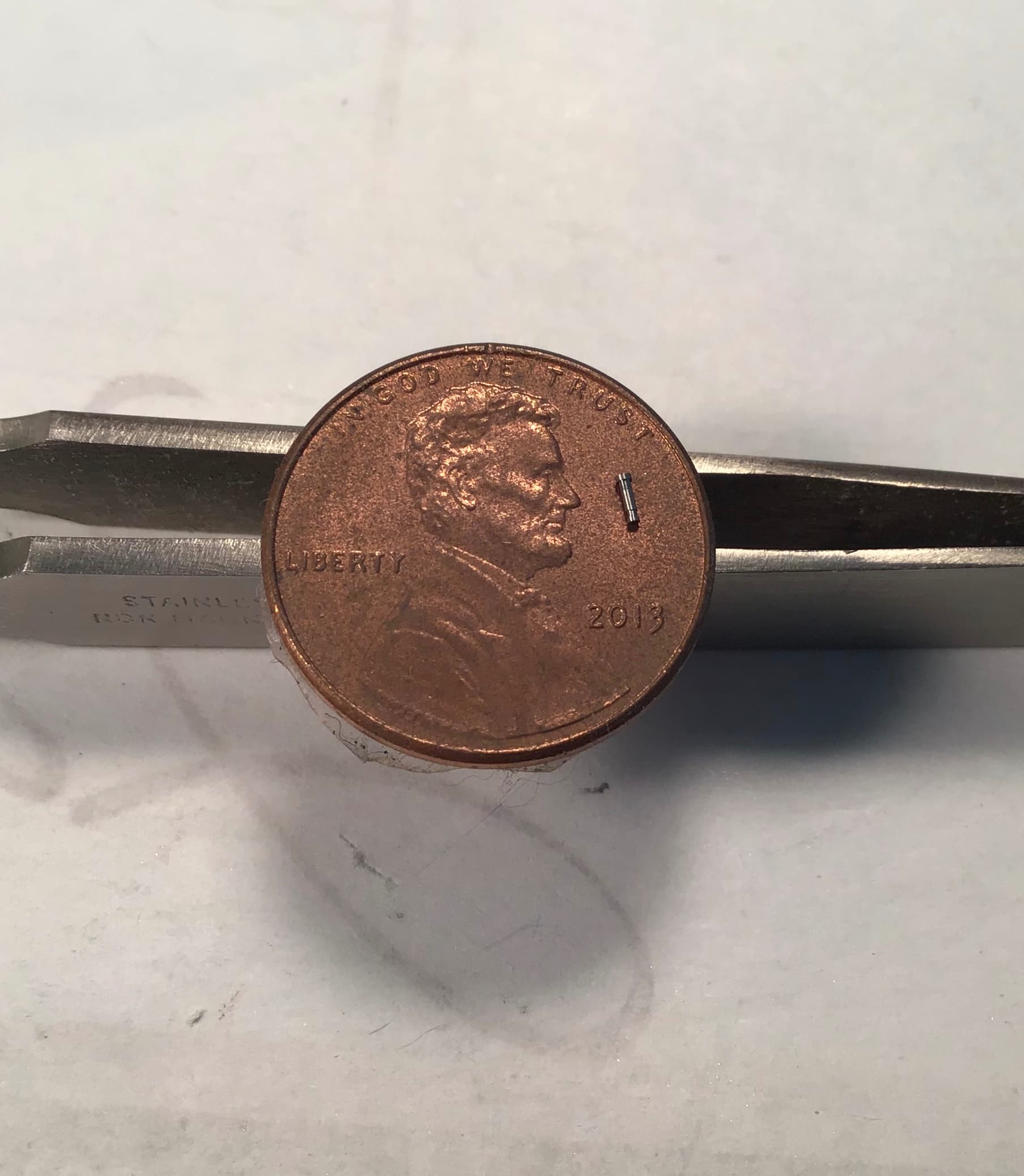
And a shot of one pin on a penny for sense of
scale . These are actual miniature turnings with a head on one end and a groove to accept the links on the flip side .
The jig will now be turned over and opened up to accept the PE links for the other side . What you see here is about two hours work .
To be continued…
4 Likes
Richard,
Tamiya surely pulled out all the stops to create a scaled chain, but one surely needs excellent eyesight, something that I certainly don’t have to accomplish this assembly.
I’m looking forward to seeing how you lock each link of the chain so that it stays together after removal from that jig. I’m also assuming that you have to cut each link out of that fret on both sides, and then file the burrs off.
joel
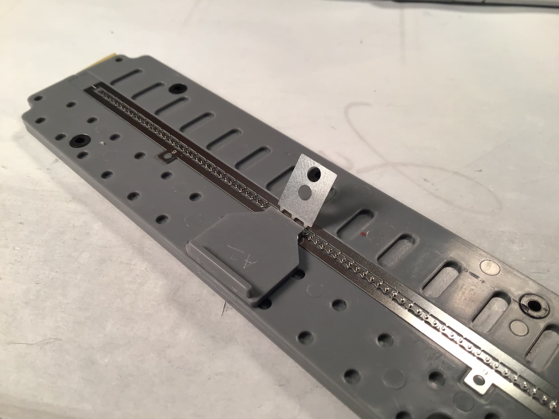
The next step in the process is to turn the jig over and remove the top piece thus exposing the ends of the pins with the grooves .The matrix around the links is carefully cut away by making many passes with the hobby knife along the scored edges of the links.
Tamiya supplies the connecting links in groups of three with a substantial tab with two holes that correspond to pins on the plastic piece. One plastic piece holds the closed side of the link down and the othe plastic piece is used to pull on the large tab to snap the open sides around the pins.

After snapping in place the tabs are scored and broken off then the process is repeated down the line.

When all is done the remaining matrix around the links is cut away as on the first side.
And then the jig is disassembled and the the chain removed.
The ends are then placed in a different part of the jig and joined together in the same manner as the chain was built.
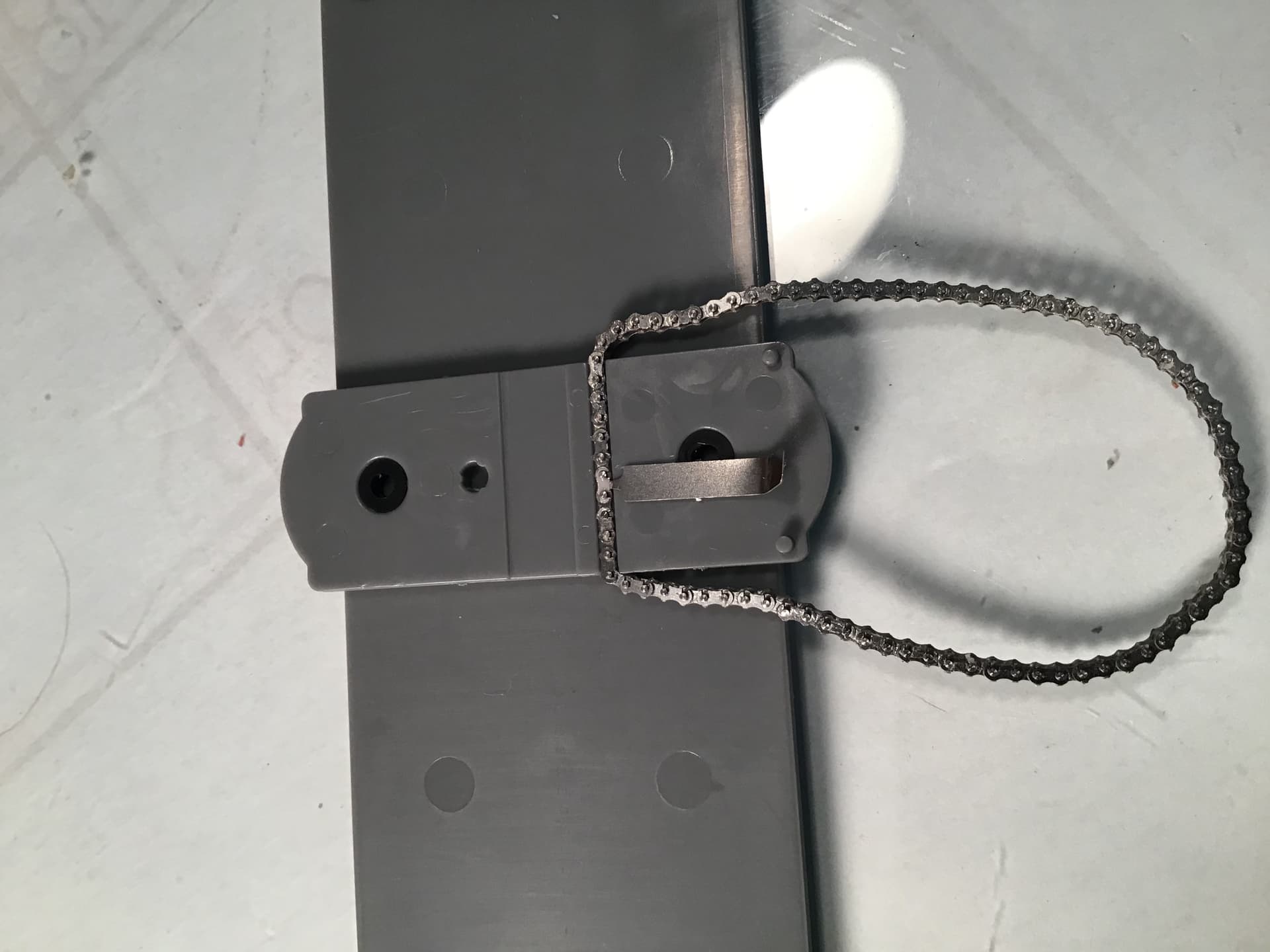
When initially removed a few of the links at one end began to come apart . I carefully repaired them - no easy task without them being in the jig- and then I placed the chain on the glass plate and against a straightedge and brushed on a highly thinned coat of acrylic matte medium to help hold all together.
Thanks for looking !
RT
2 Likes
We are not worthy!!!
2 Likes
That chain is just wicked. 
1 Like
I know how difficult that chain assembly is and when the occasional link wants to slip off how fiddly that can be so that’s a great outcome. Looks good on the bike too.
cheers
Michael
1 Like
Richard,
OMG!! that chain is simply amazing. You made the whole process look way to easy from start to installed. And lets not forget how quickly you got it done. I’d be working on it for weeks on end till I loose enough pins and links to need to buy another kit.
joel
2 Likes
@Tank_1812
@Joel_W
@loncray
@joelsmith
@AussieReg
@cosimodo
Thanks gents but the credit really belongs to Tamiya
- they made it very doable. Tiny pieces to be sure .
I would love to see the lathe in operation that made the pins .
Cheers - RT
1 Like
Richard,
You’re selling yourself short. I’m betting that more then just me would have screwed up that chain no matter how many jigs and aid Tamiya supplied.
joel
2 Likes
By necessity Tamiya uses a number of tiny screws for assembly. They do a great job and make secure connections but they are a little unsightly.
I punched out some thin styrene hex shapes with a punch and die set and glued them over the offending screw heads with CA . They will be painted up later .
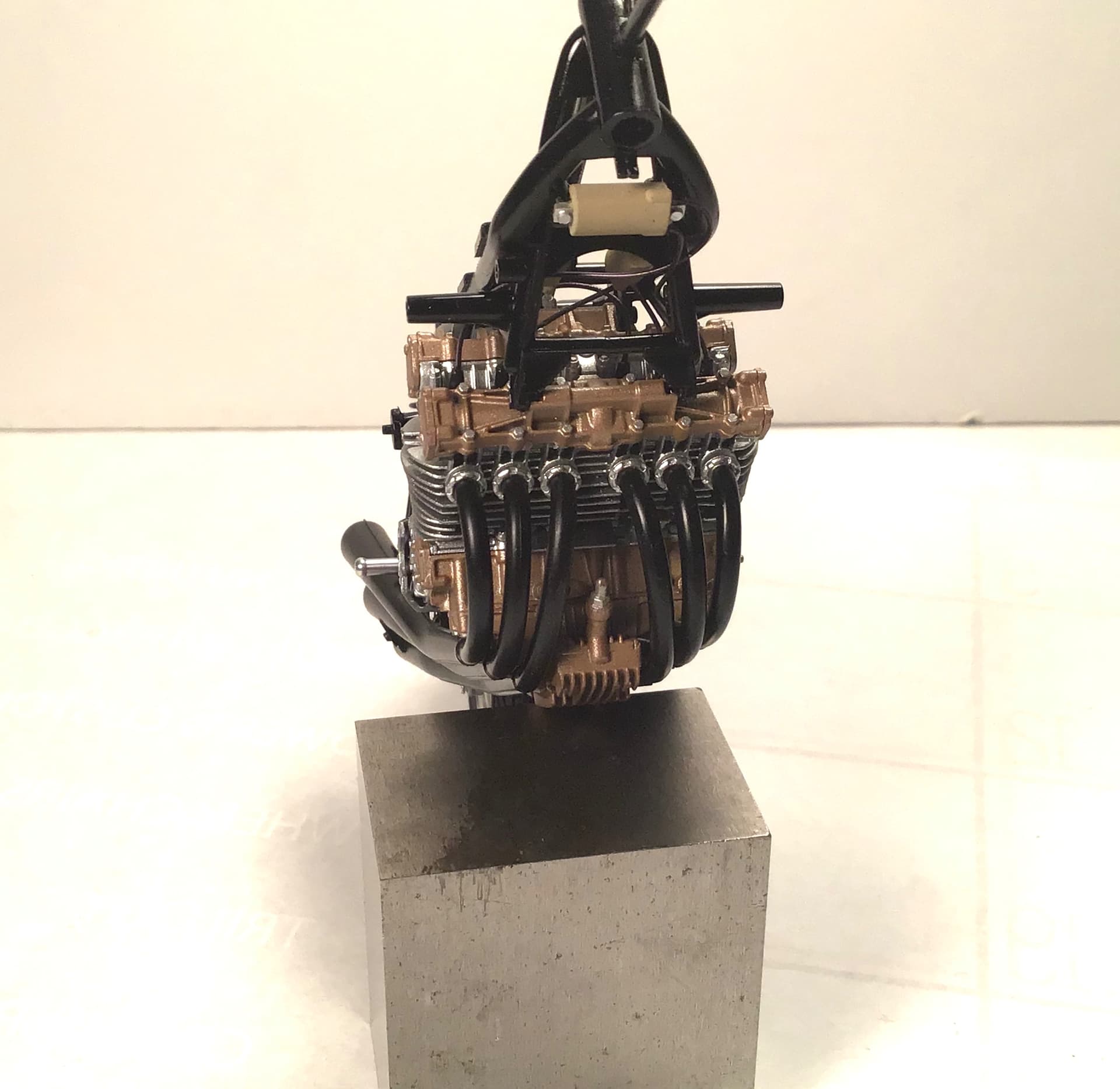
Finished up the exhaust system as well - another tip of the hat to Tamiya on this as all the components fit perfectly - even six tiny exhaust roses at the cylinder head .
4 Likes
That chain is a work of art. And you made it look like something that even a mediocre builder like myself could (possibly) build the thing. Fortunately (for my wallet), this is outside my preferred genre of ultra-modern crotch rockets, but it’s still more tempting than any other chain assembly I’ve seen.
1 Like
Richard,
Once again you’ve taken an outstanding Tamiya engineered’ 1/12 Bike kit and found away to kick it up another few notches.
If it was me, I wouldn’t have given the hex head screws a 2nd thought as their function of holding two pieces together worked perfectly, yet you came up with a better idea of a hex plastic plug.
Out of curiosity, the hole for the hex screw, is it round so that a regular plastic plug that I could have made work as well? I’m asking as early this Jan/22 I’ll be starting my very 1st every 1/12 Tamiya F1 build, and I’m sure that they’ve got those hex head screws as well.
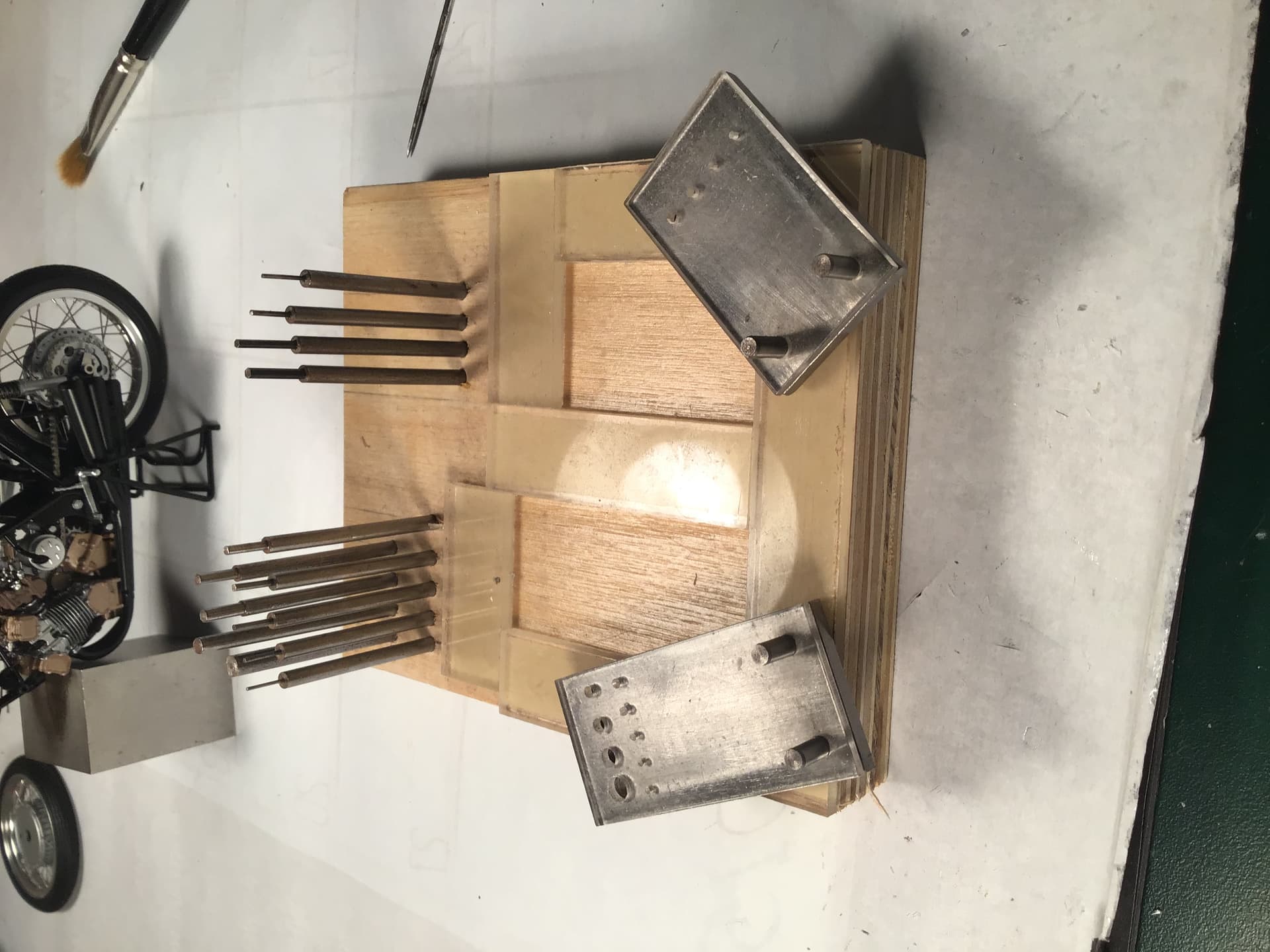
BTW, that’s some base for your punch set. It’s giving me a few ideas i just might try. Did you split the clear acrylic base into 2 sections as that would be pretty close to my set?
joel
Thanks again Joel for your continued interest and kind words.
The screws Tamiya supplies are not hex head - they are regular round head with Phillips type cross slots . While I don’t want to seem pedantic , these may not be actual Phillips but a very similar pattern known as JIS . The difference lies in the grind of the screwdriver that turns them .
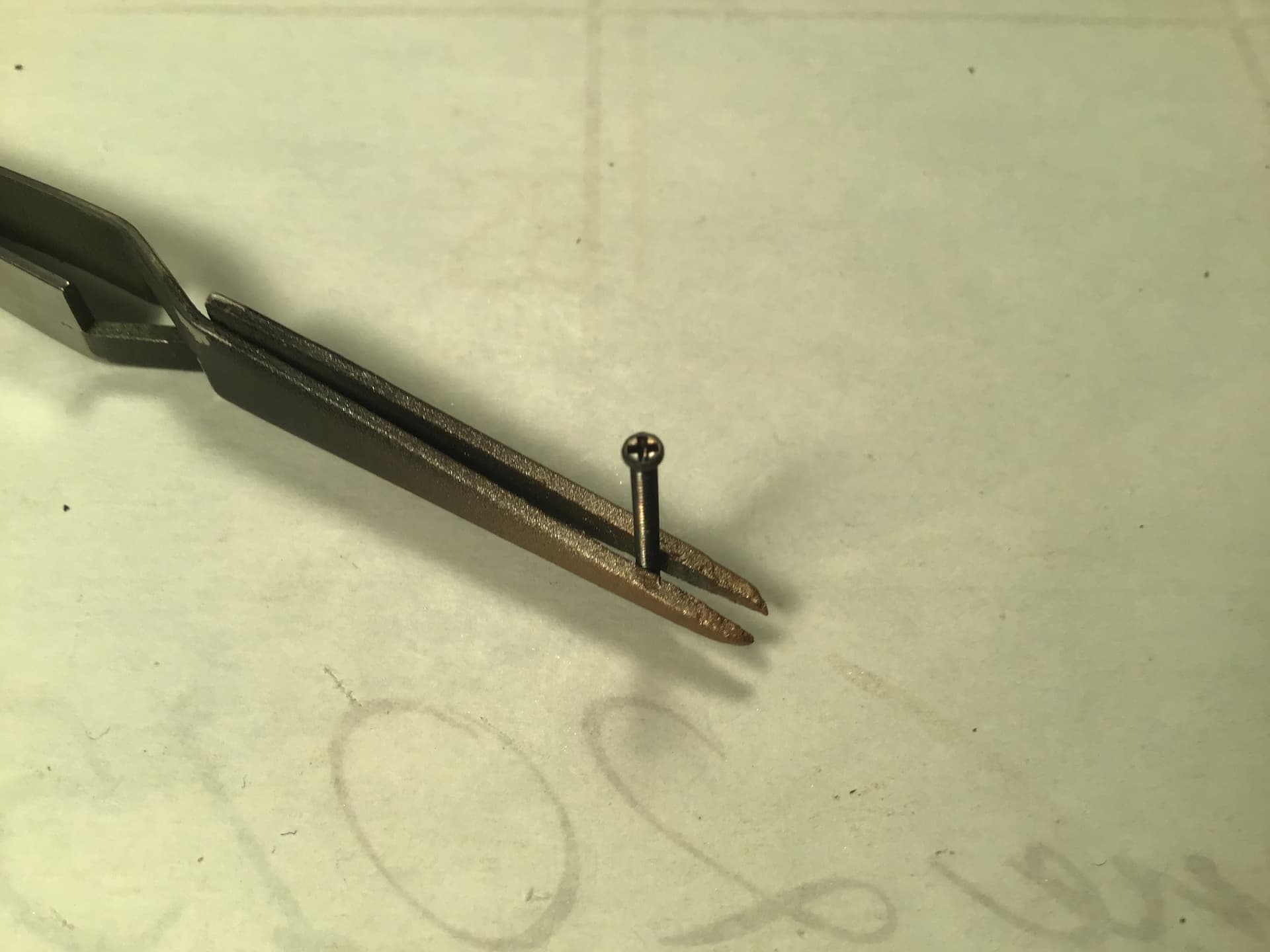
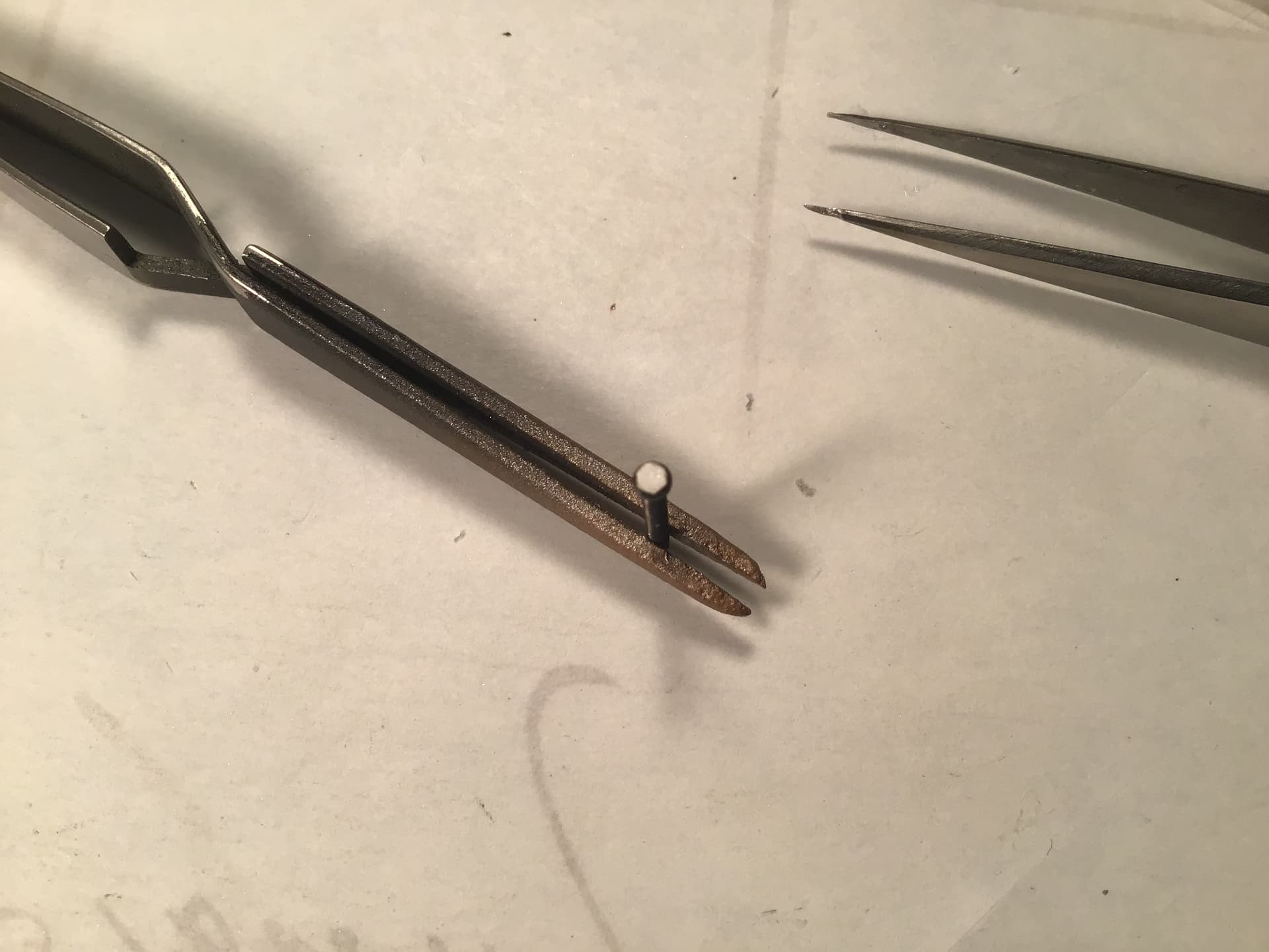
When installed they go into a round recess but the head of the screw stands proud of the recess and detracts from the model because the real motorcycle doesn’t have giant screw heads in plain view . What I made isn’t really a plug but simply a cap covering the head of the screw , held in place by CA adhesive . Here is one on the point of a needle…

And in place on a screw…
My punch and die set is a hand me down from my brother in law Jim - gifted to me when he replaced his with a new and better set . It consists of both round and hexagonal punches.
Hope this helps explain.
Cheers- RT
3 Likes
Richard,
Thanks for the explanation, and on those screw covers. Not sure why Tamiya would put in the effect they did on these bike kits, then leave those hex screw heads sticking up above the skin surface.
joel