Hi all,
Progress has been made although I must confess that these days I am splitting project time about 75% planning and 25% actually working on the model. There are just so many issues to work out with the hull detailing  and no reference material does these elements justice. Anyway, I’m actually having a blast with all this research and I think the results are paying off.
There are currently four tasks I am tackling on the model, each of which is worth an update post, but only one is ready so…
Let’s talk about portholes!
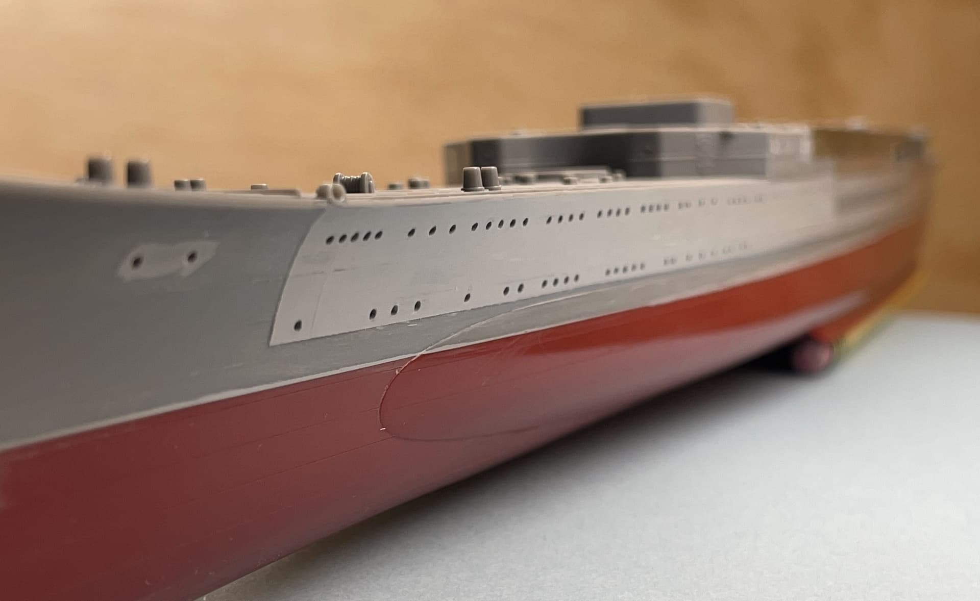
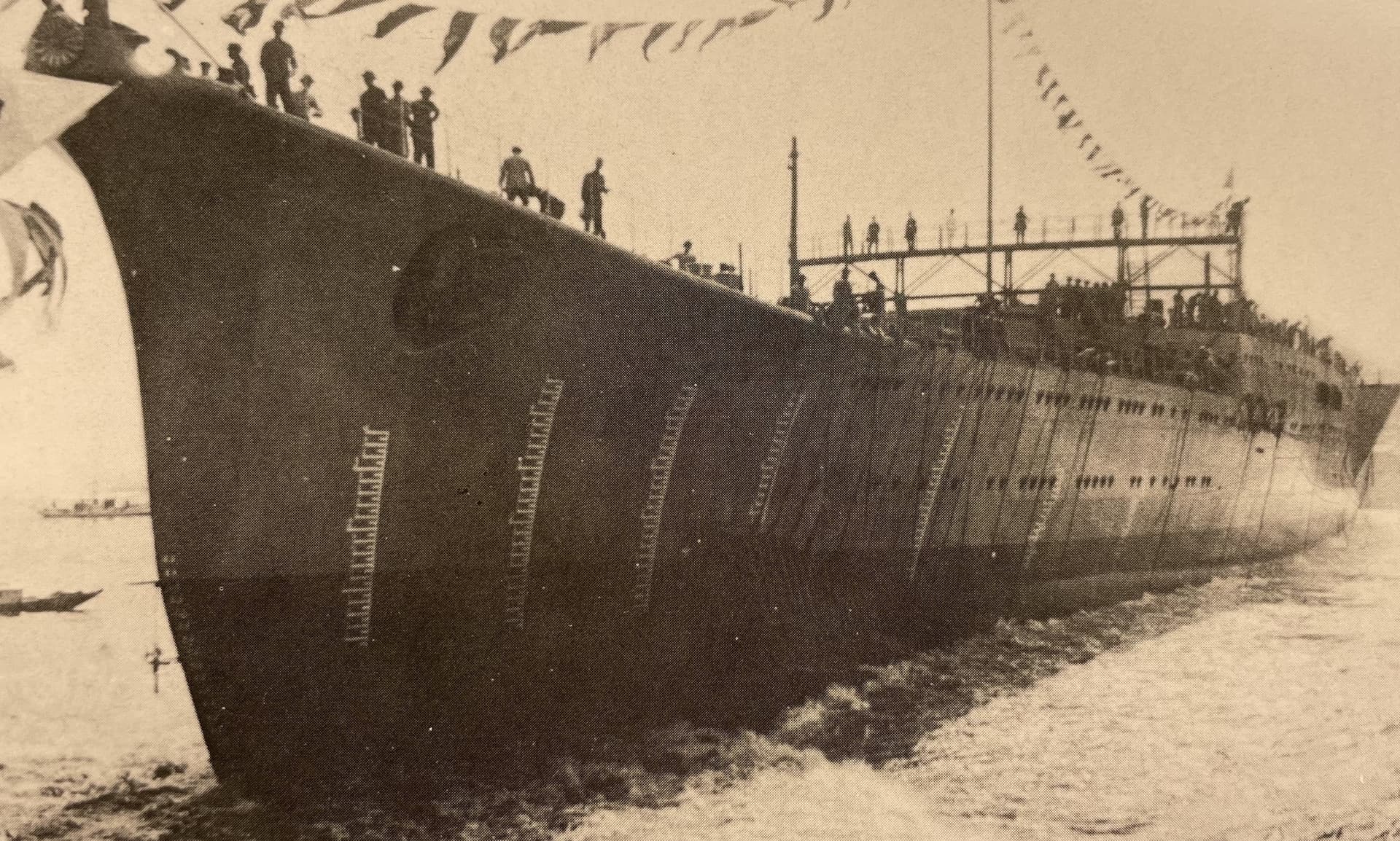
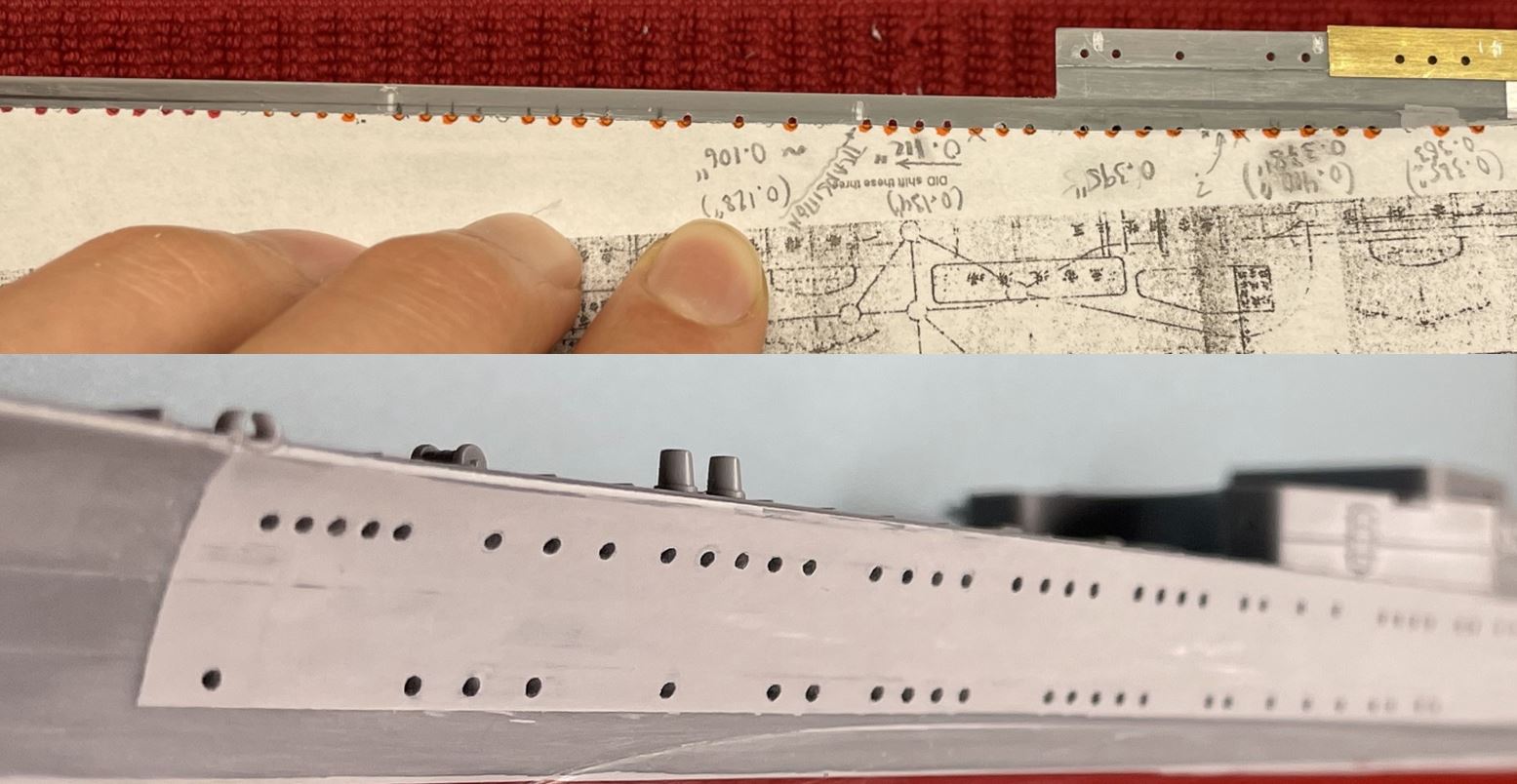
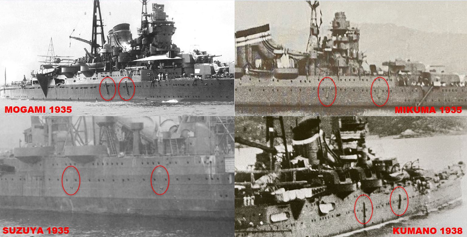
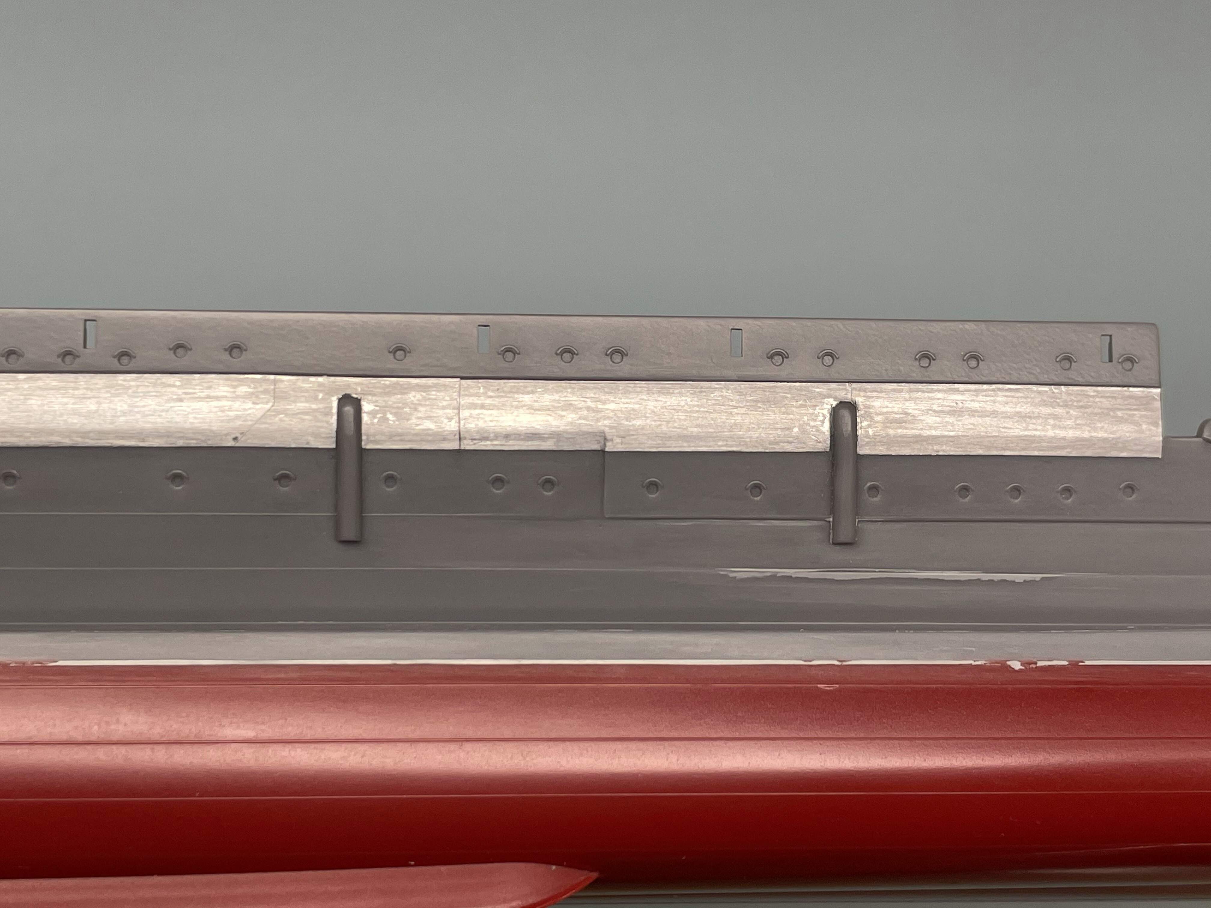
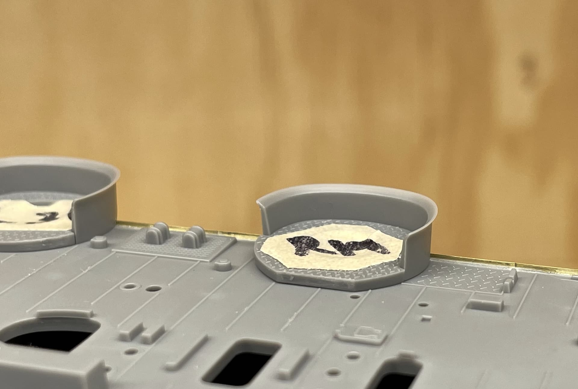
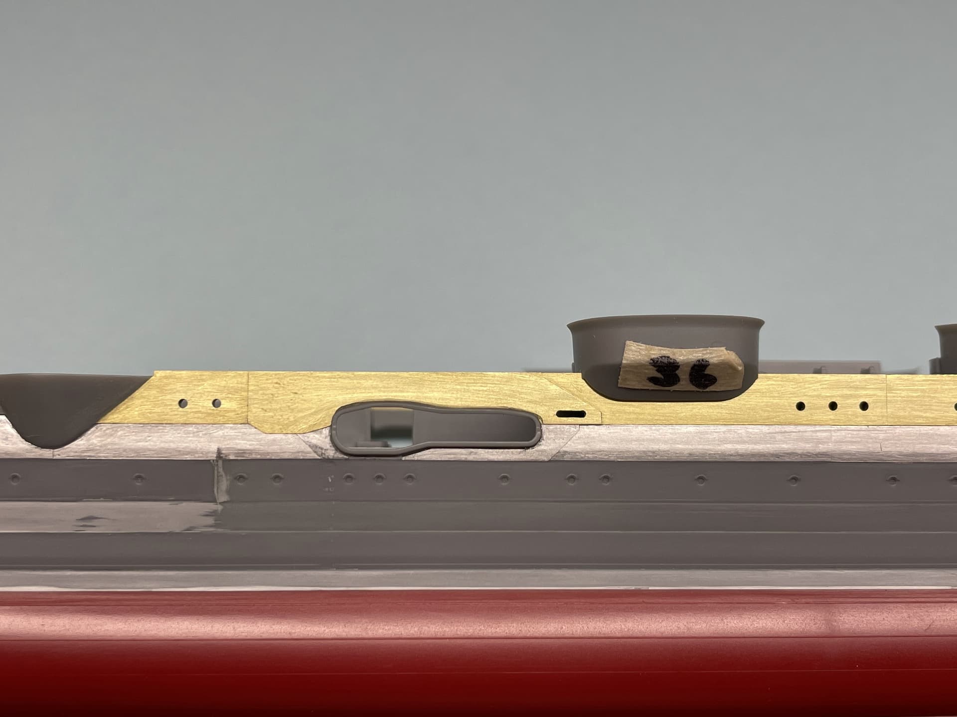
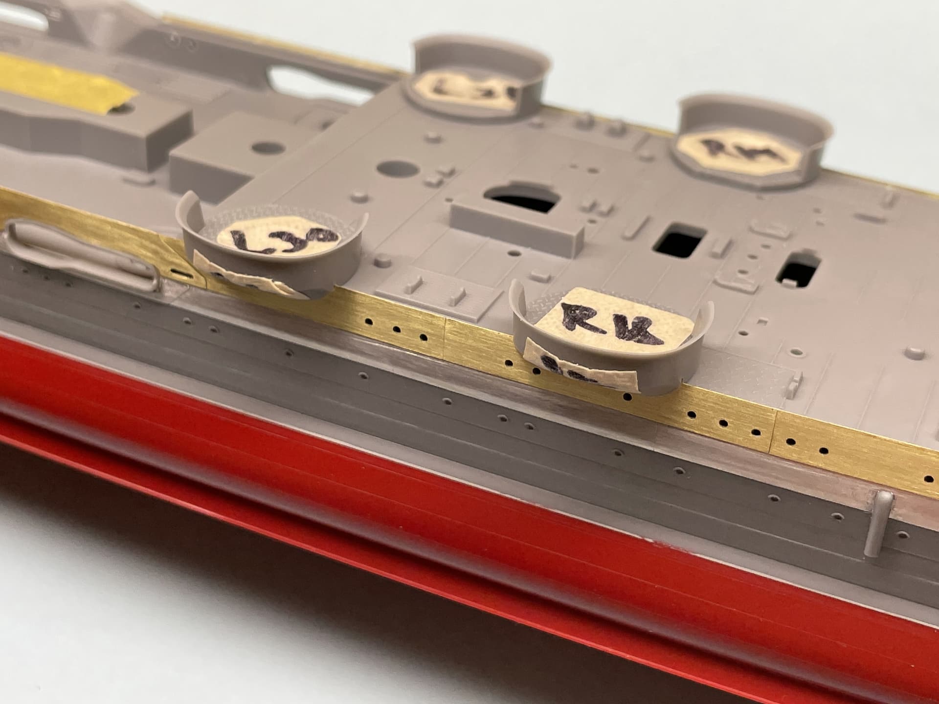
75 more portholes have been drilled on the port side bow, middle and lower decks. Brass plating will come later as the stern portholes will be up next (to give myself a bit more time to finalize my thinking on the shell plating). It doesn’t really shown up in this image due to the potato cam, but the middle deck portholes follow a horizontal line until they are level with turret No. 3, where they dip down slightly. The compound curvature of the bow made lining up these ports a real pain, as in this case: horizontal line does not equal straight line. This photo of Mikuma during launch is the best reference available for the port side bow portholes, and was essential for this step.
With that small update out of the way, I thought it could be informative to expound upon my thinking behind the general layout and placement of these portholes. As you may have noticed, I have shifted every porthole to some degree from its original position (as molded by Tamiya). This was relatively easy to accomplish in material terms, but required months of effort on my part in terms of research and planning. While I am impressed with the engineering and fit of the kit (it literally snaps together seamlessly) I am less than thrilled with the placement and scaling of many of the smaller details. It did not take much analysis of the kit to determine that virtually every porthole was undersized and incorrectly positioned.
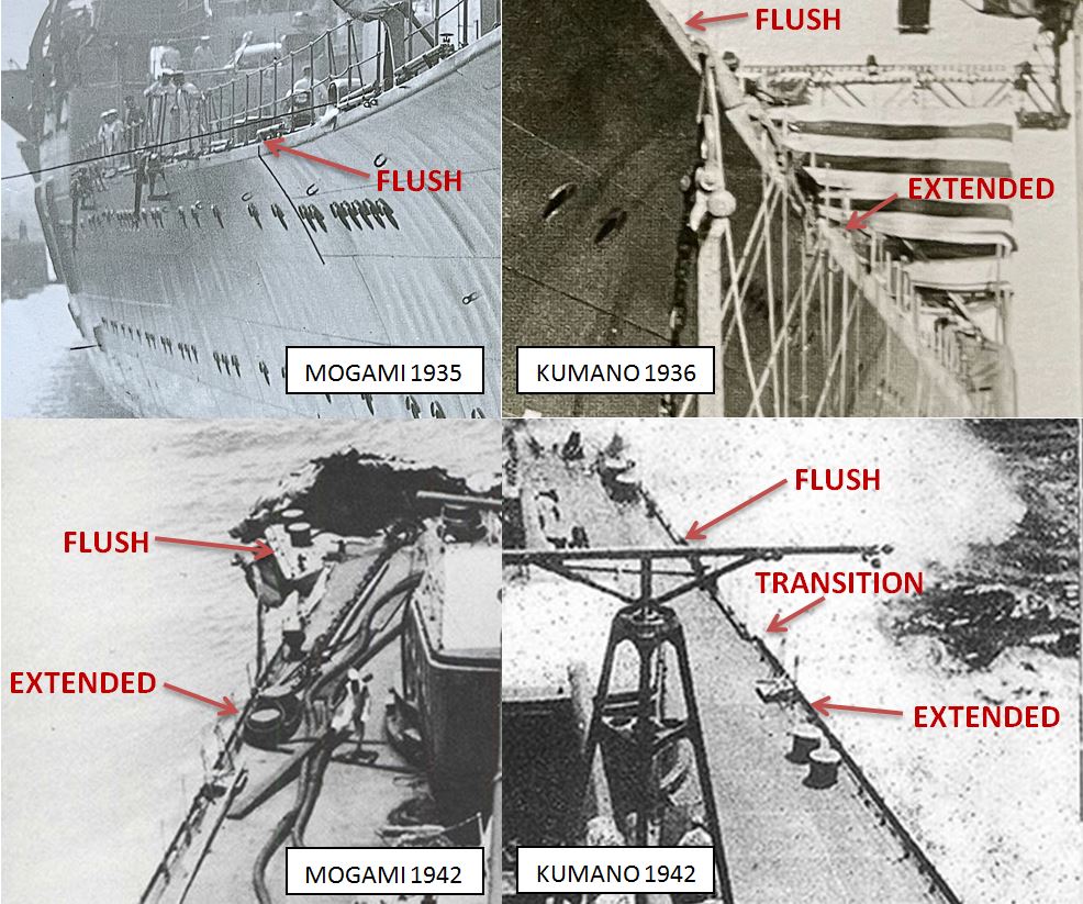
Now, on many warships the portholes are laid out in nice straight lines on one or two decks, with even and consistent spacing; not so with these IJN heavy cruisers. The portholes are arranged in undulating lines with variable spacing across many decks. Also, there are so many of them, and each ship of the Mogami-class has its own unique layout. Further muddying the waters is the fact that a handful of these portholes were removed or shifted during the Second Efficiency Improvement Works. Fortunately, the changes are reasonably well-documented in photographs and it is possible to create porthole layouts for each ship, with decent accuracy. I have yet to find a reference book that comes remotely close to accurately portraying these porthole layouts, which is why it has become such a point of focus for me. I hope that this thread may help others in the future who wish to enhance the accuracy of their Mogami-class builds.
(Be warned, I’m an incorrigible porthole counter, but you knew that already  )
)
So, if you are interested, here is the convoluted process I followed:
1. Gather all useful images of the class that show porthole positions (primary source material).
I eventually collected 10 of Mogami, 8 of Mikuma, 11 of Suzuya, and 3 of Kumano. All my reference books have been invaluable.
2. Compare these images to the existing secondary source material.
These secondary sources were the Tamiya model, any profile view drawings that included portholes, and Model Art Super Illustration isometric drawings with portholes shown.
3. Realize that the primary material contradicts the majority of the secondary source material.
I quickly cast aside any ideas that were brewing about using the secondary material as a reference for porthole positions.
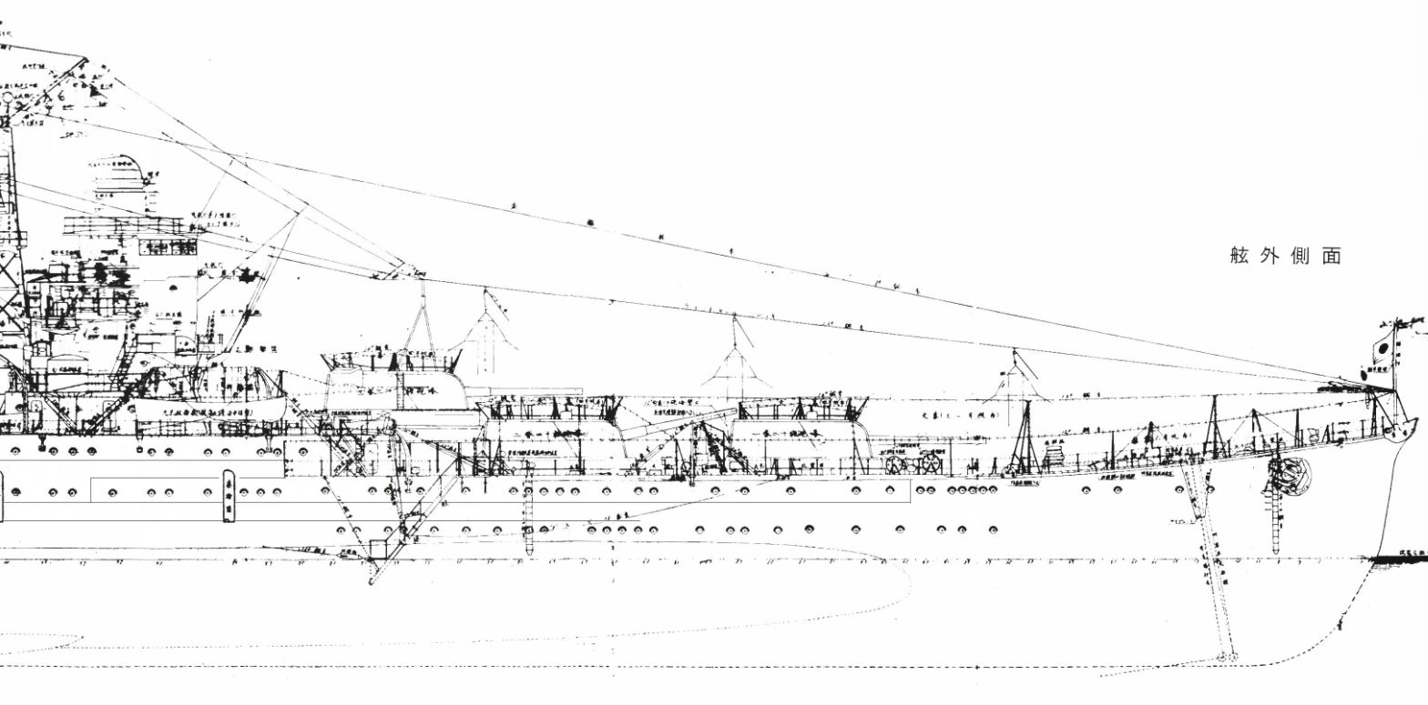
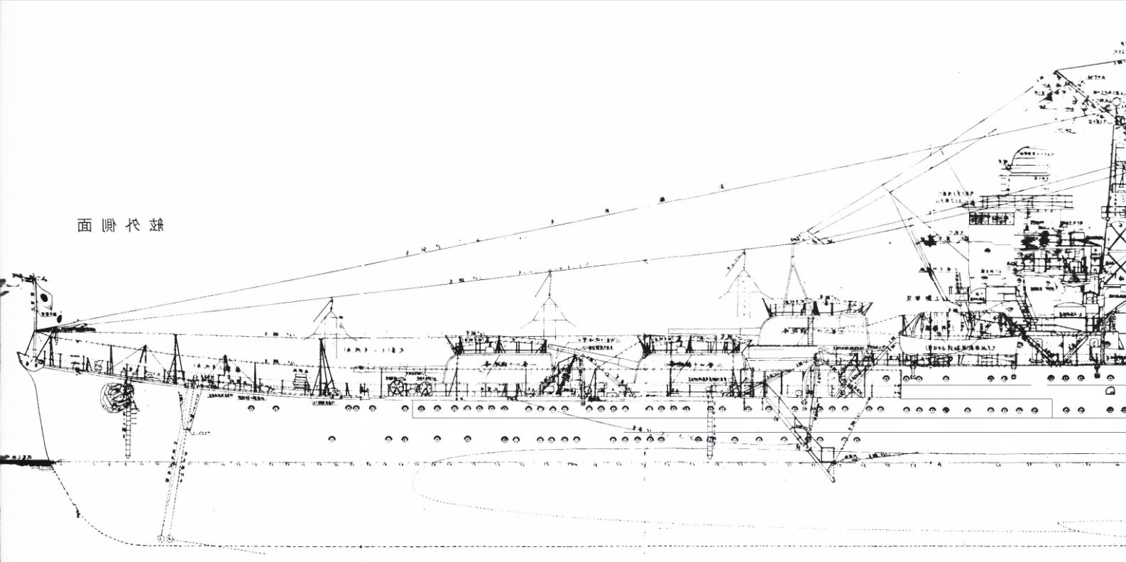
4. Take an existing profile view to use as a base for a corrected porthole layout profile view.
For this I used a high-resolution scan of 1938 Suzuya plans which I found for free online, but it was originally sourced from the ($900!) Plans of ships of the Imperial Japanese Navy, History of shipbuilding in Showa era separated volume, 1975).
5. Use all available images to determine the correct porthole positions and draw them onto the plan.
I used MS Paint for this to be quick and dirty, although there are obviously slicker program options out there. Using the Suzuya layout as a starting point I added, removed, and shifted portholes as necessary to conform to the reference photos. I created these layout plans for the port and starboard side of Mikuma for both the 1935 and 1938 refit conditions. Of course, once the first one was created there were just small tweaks that needed to be made to create the other plans. It is important to realize that although the ships all had different porthole layouts, about 75% of the portholes were in common locations, and that they are all fit into a sort of “grid” formed by the frames and decks of the ship. The last important thing to notice is that Mogami and Mikuma have very similar porthole layouts, while Suzuya and Kumano are likewise nearly identical. There is however a huge difference between Mogami/Mikuma and Suzuya/Kumano.
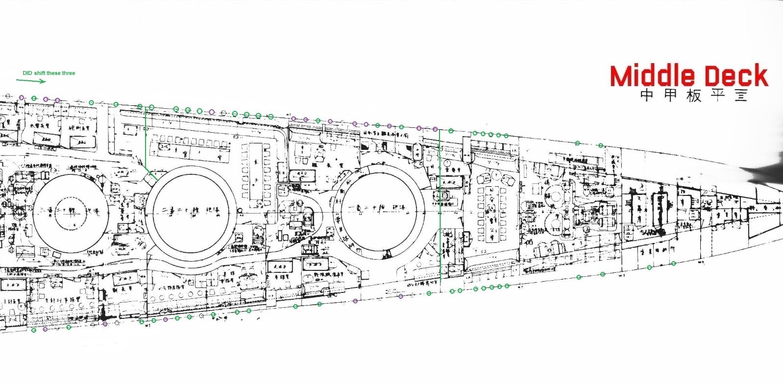
6. Turn this information into a dimensionally accurate template to be used for setting the position of portholes to be drilled, and double checking these positions after drilling.
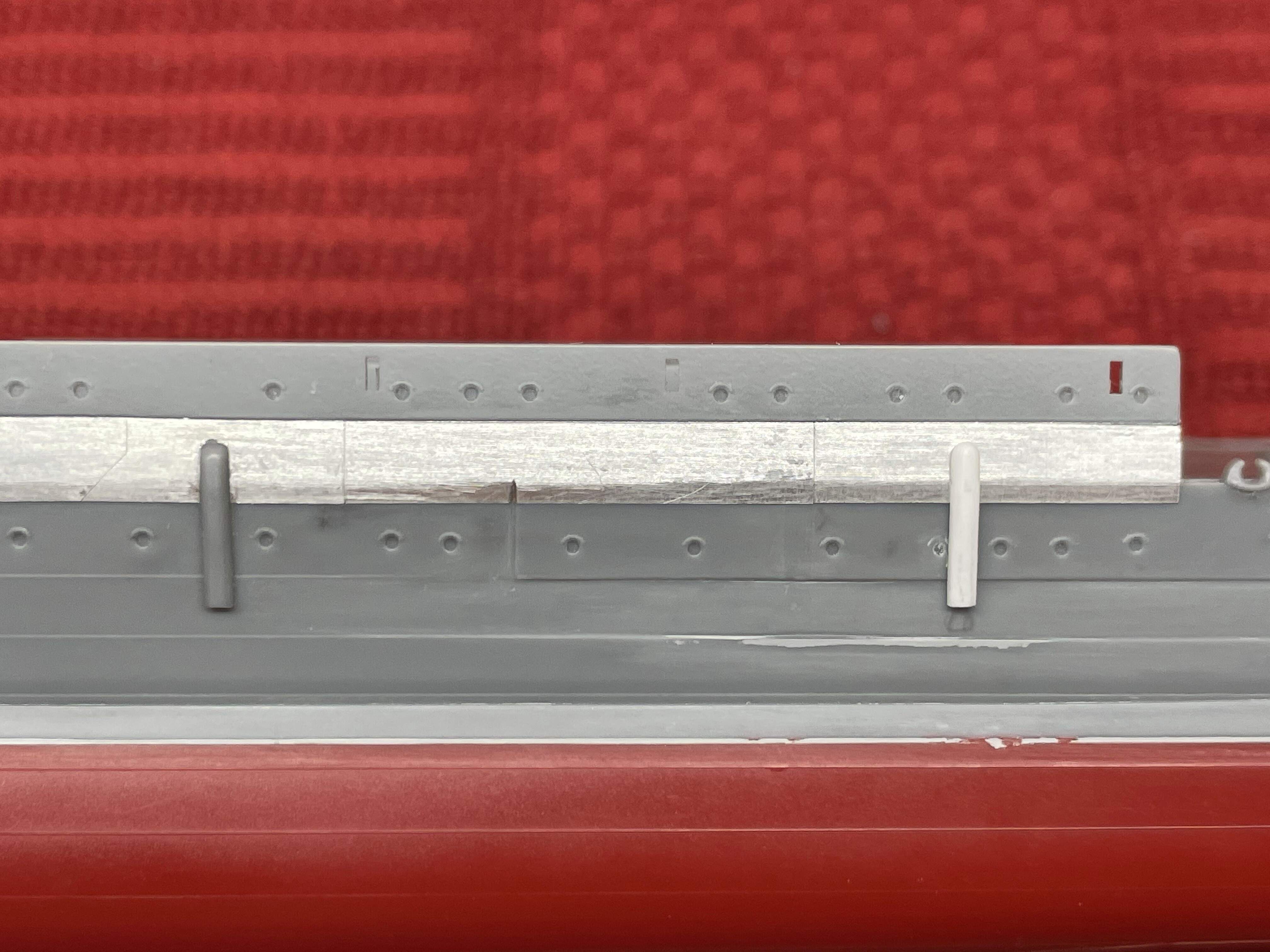
I actually completed steps 1 through 5 back in June. More recently, I discovered a scan of the complete deck plans of Suzuya (also from Plans of ships of the Imperial Japanese Navy, History of shipbuilding in Showa era separated volume, 1975) which shows every porthole location on every deck! I used the porthole layout profile views created in step 5 as a general guide to create modified porthole plan views of each deck with porthole positions specific to Mikuma 1938-1941. See below: green represents common to Suzuya and Mikuma, purple is Mikuma, and black is Suzuya. The modified image was then scaled and printed at 1/350.
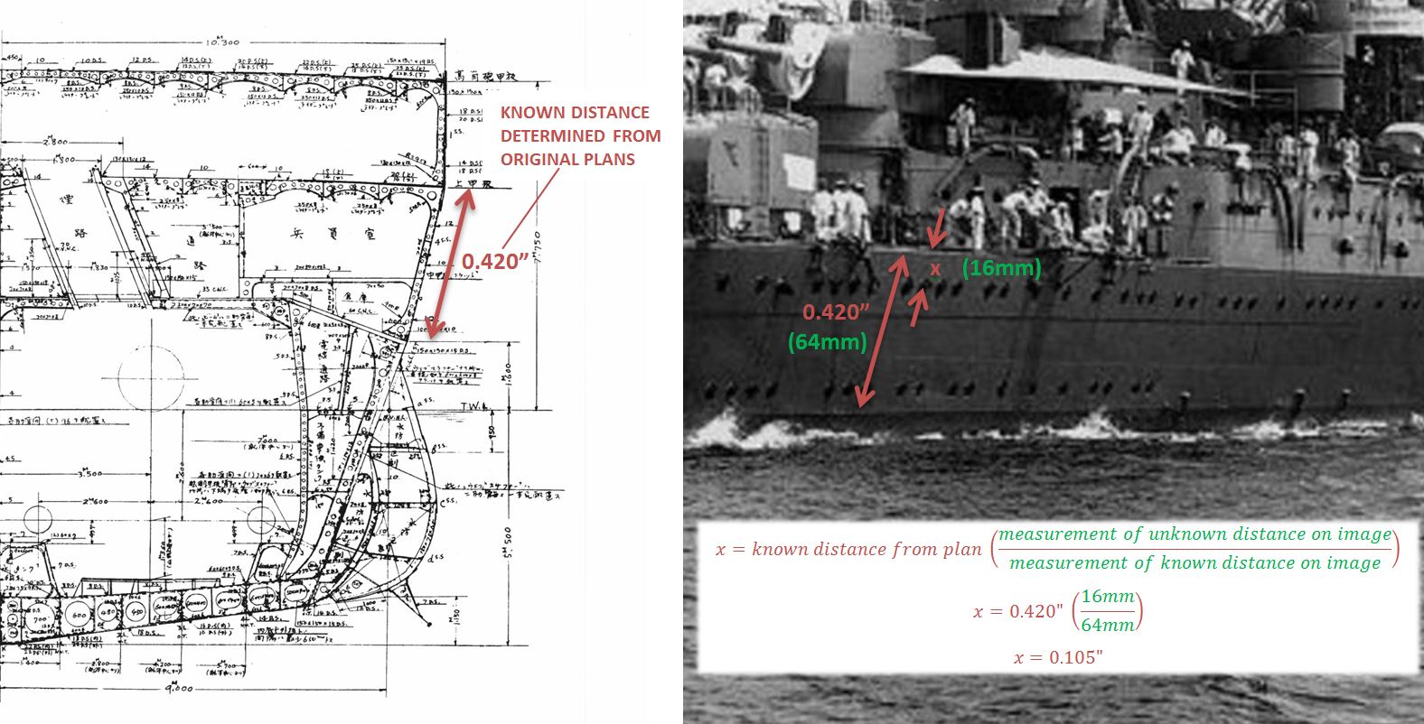
7. Determine the vertical position and size of portholes.
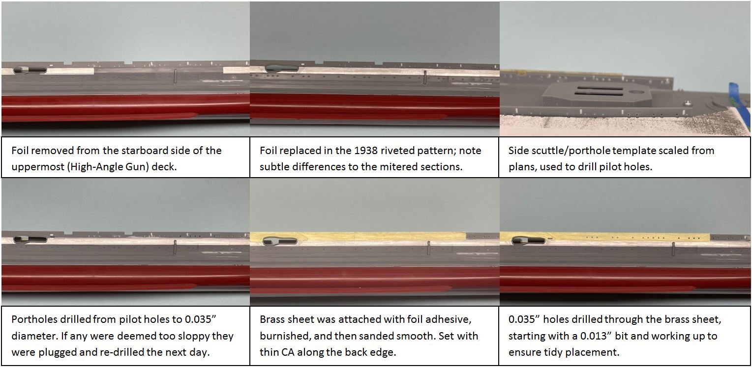
For this I relied mostly on proportional analysis of photographs. I started with a known hull dimension from plans, usually the distance from the top edge of the armor belt to the top edge of the shear strake, measured along the hull. This dimension is 0.420” and is consistent along the hull and clearly visible in most photos. Then, I measured this distance on a photograph in millimeters (because metric rules), the distance I wished to determine in millimeters, and used some simple maths to find the unknown distance. The same process was used to double check porthole sizes which I pulled from scans of the original plans of Mikuma and Suzuya.
8. Use the template to drill pilot holes, then adjust hole positions as needed.
Measure twice and cut once as they say, although this was more like measure ten times, drill three times! I often had to plug holes and re-drill them as it was very tricky to get these dense strings of portholes to line up neatly. This mess was cleaned up with an application of thinned Mr. Surfacer and some sanding.
Hopefully this guide was illuminating and helpful to anyone wishing to do something as bonkers as repositioning hundreds of portholes on their model ship. Moving forward I plan to add portholes to the stern, then the complete the shear strake brass plating. Hopefully everyone following this build will forgive my snail’s pace and stay tuned for future updates.
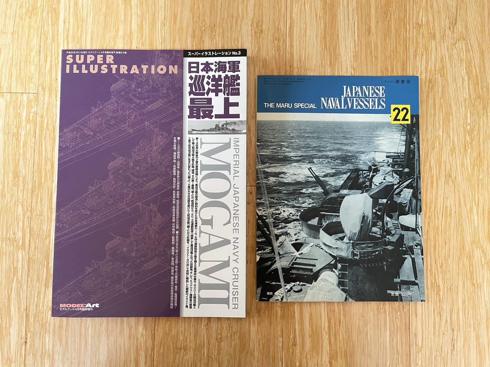
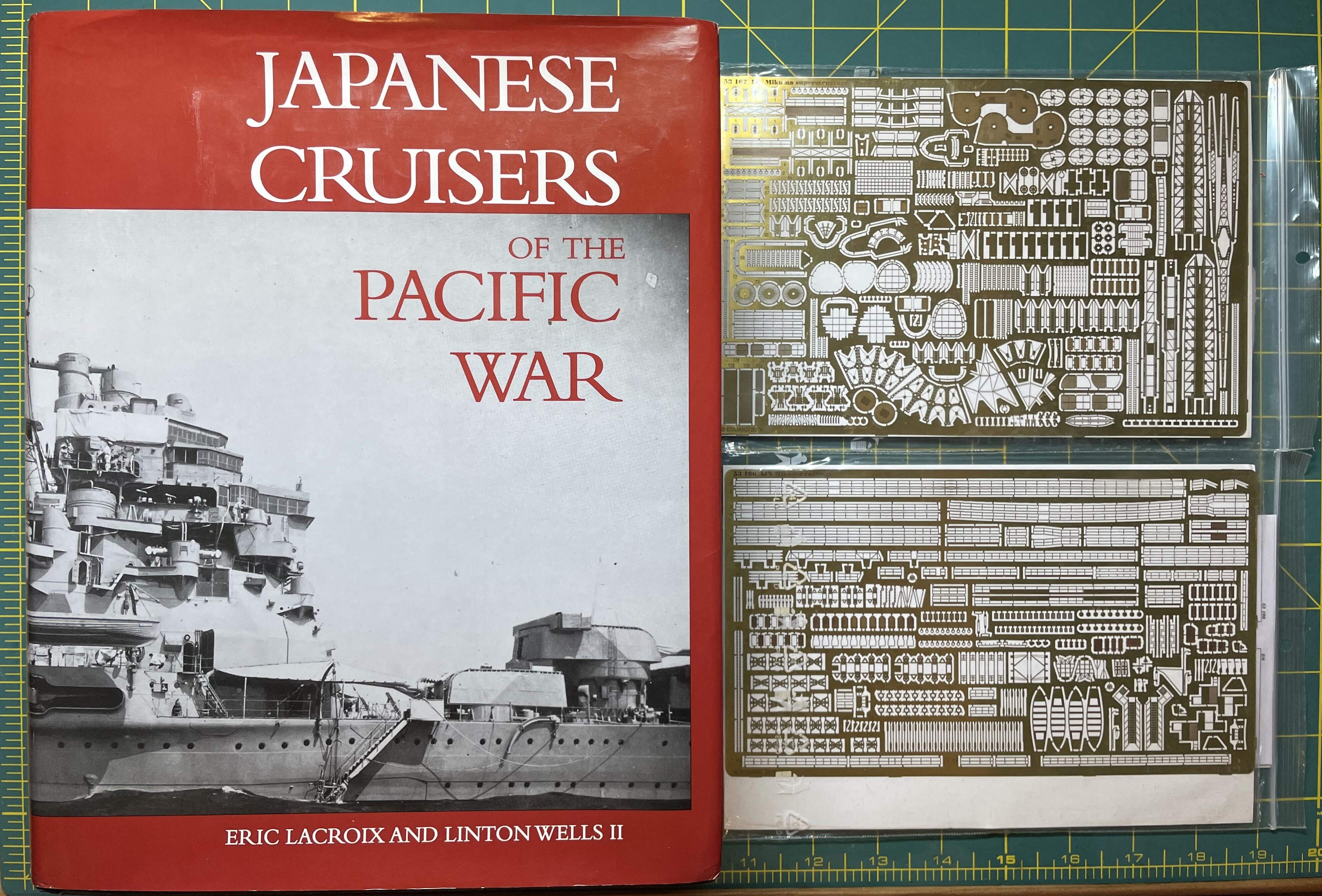
In other news, some reference materials I have coveted for many months were recently acquired:
Because you can never have enough boat books.

Marty

 it’s been a while.


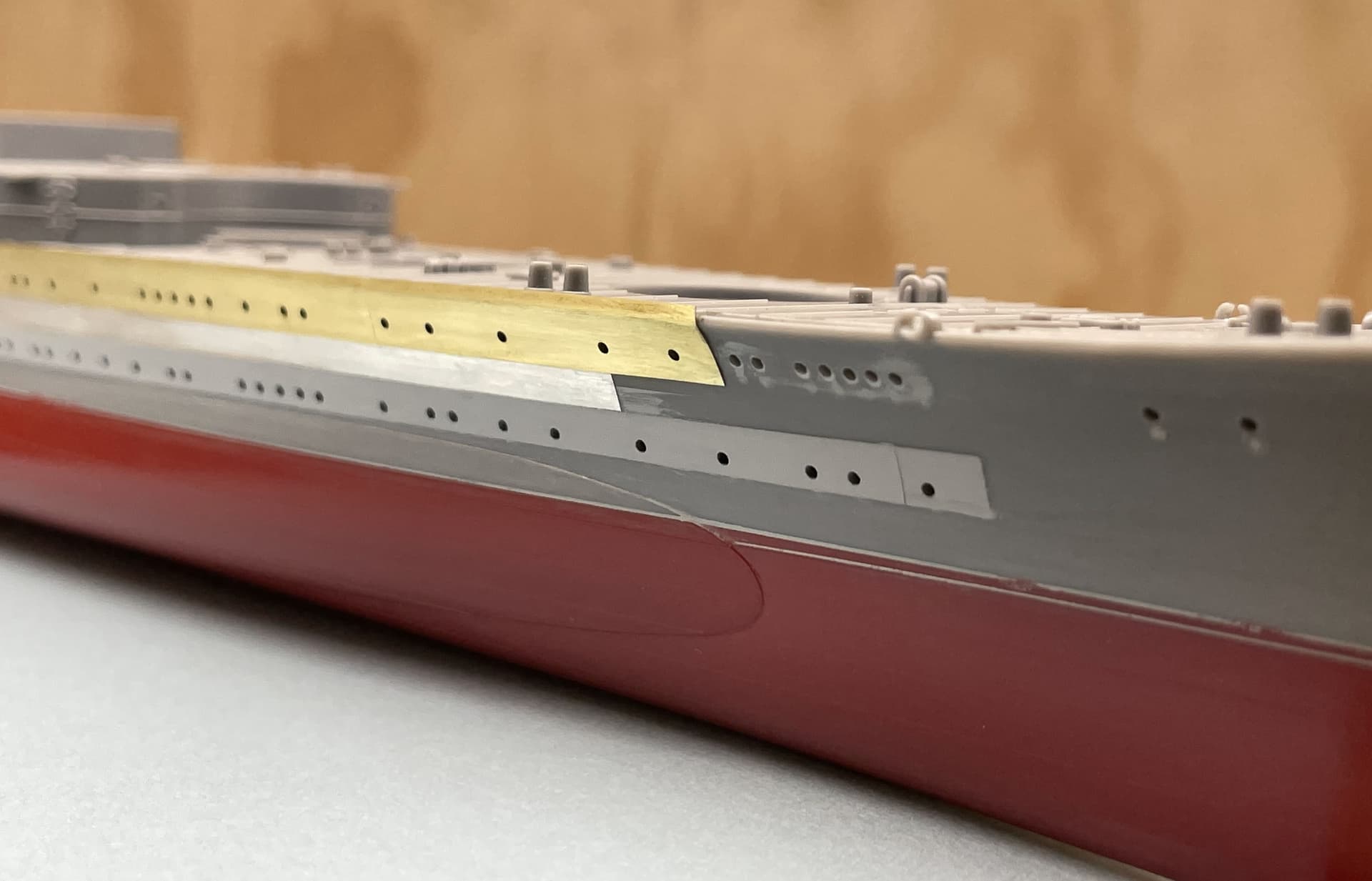
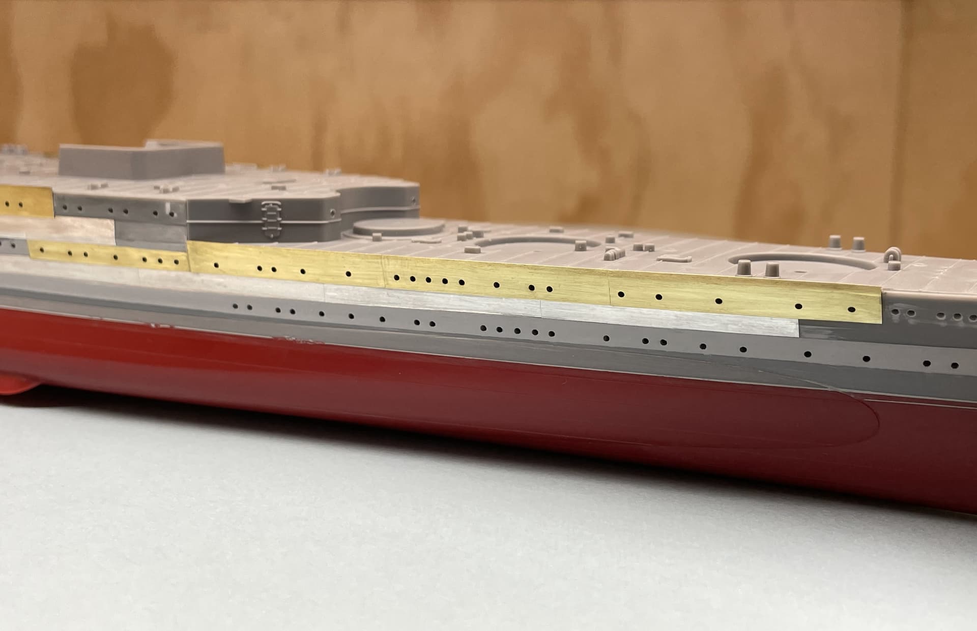
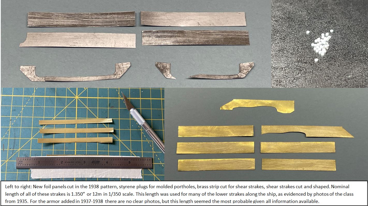
 but I accomplished a bit of planning during the (seemingly) interstitial time. Templates were created to aid in the marking of porthole locations prior to drilling. Also took some time to work out the dimensions of the shear strakes at the bow and stern of the ship. Now that I am back at the bench, porthole drilling has commenced on the lower decks and I have begun making some really nice improvements to the bow plating, more on that to come.
 Cheers,
 Hi all,