Wow! Very thorough research, Marty 
2 Likes
Hi all,
@RDT1953 @Russelle Thank you Richard, Tom, Tim, and Russell for the kind words and encouragement!
@Shanghaied I promise I was sane before I started this project, now I am not so sure, but the research has been a rewarding element so far!
@TimReynaga I like to think I would have set Tamiya straight if I had been involved. But after looking though my recently acquired Model Art Mogami Super Illustration, the errors in this kit make much more sense. It seems that both the Model Art book and the Tamiya 1/350 kit were derived from the Miyukikai Mogami plans. This is unfortunate as, although there are many good things to be said about the Miyukikai plans, they also include a number of errors, one of which is the porthole layout (a confused hybrid of the as-built and final layouts for Mogami and Mikuma). I suppose Tamiya thought the plans were authoritative.
I have been moving along with porthole drilling on the stern of Mikuma (all portholes amidships are finished) which has been going swimmingly. However, I overstated my confidence in the bow porthole positions.
After further review of two images of Mikuma from 1939 it appears that a few subtle changes were made to porthole positions on the bow that I missed on first inspection. The changes were mostly on the port side middle deck level; basically a bunch of them were removed when the plating was reconstructed in 1936. Almost identical changes are documented for Suzuya at the same time, so I have a rough idea which portholes need to be removed on Mikuma, but the quality of the port side photo is so poor it is hard to be sure.
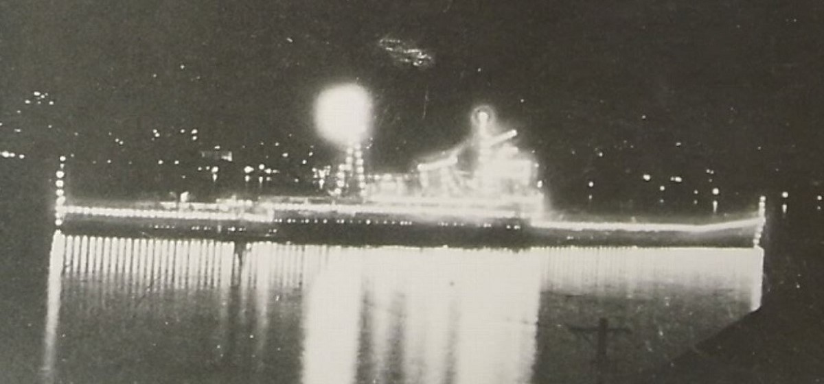
I have one additional image of 1939 Mikuma that I found online months ago, but it is basically a thumbnail. If anyone knows of this image, or where I could find a higher quality version, it would be very helpful. I can’t seem to locate it anywhere online and it is not in any of my reference books. Even in this very low resolution version, some of the portholes I am interested in are almost visible. So close and yet so far…
Anyway, in the meantime I will keep plugging away on the stern of the ship 
Marty
4 Likes
Hi 
Whoooff, I see I have been neglecting to keep this build log up to date  I have in fact been working diligently on the project; the past six weeks yielded several important breakthroughs, although progress on the model itself was less productive than I had hoped.
First, in reference to my last post, I found a caption to the image posted above:
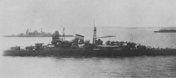
Cruiser Mikuma in Qingdao on March 28, 1939 with sister ship Kumano and aircraft carrier Ryūjō
I did not find a better quality image, but I think I have figured out what changes were made to the bow portholes from other photos.
And now, some updates:
Six Weeks Ago – Prepping the Stern for Porthole Drilling
Some corrections to features on both sides of the hull: the fairleads/chocks next to turret 3 are incorrect; Mogami and Mikuma did not have chocks in this position, so I removed these. Additionally, the sponsons level with turret No. 5 are specific to the 1943 Mogami aircraft cruiser refit, so these were also removed.
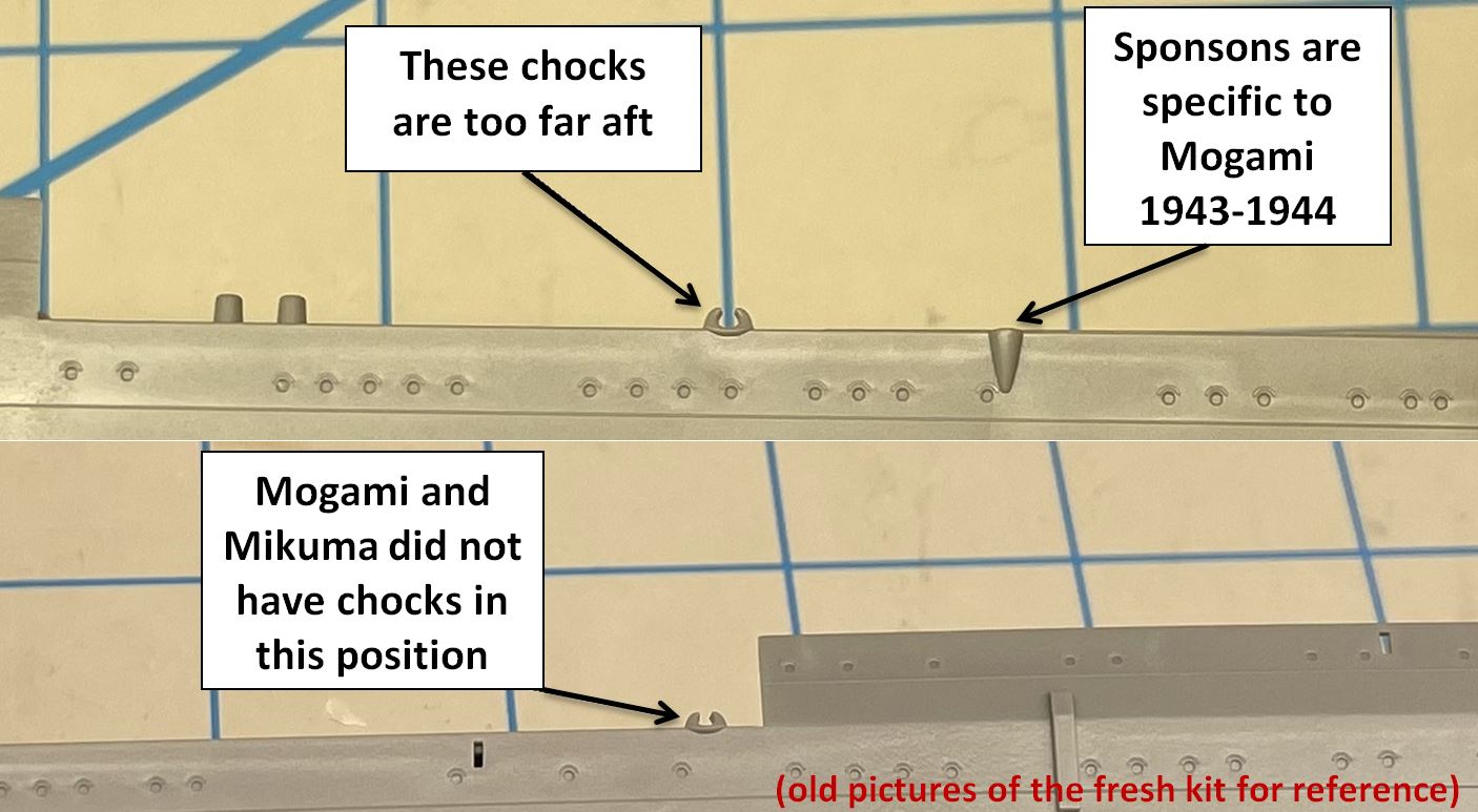
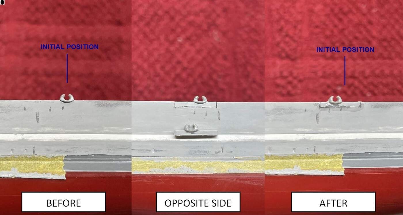
Similarly, the chocks adjacent to turret number 4 were placed incorrectly by Tamiya. These needed to be shifted forward slightly. I forget the exact measurement, but it was obtained from the scan of original 1940 Mikuma plans. I made careful cuts so that I could do a little trick and not have to add any scrap styrene. I think you should be able to figure out the trick from these pictures.
I removed all remaining hull details from the amidships and stern sections to prepare for porthole drilling.
Five Weeks Ago – Modifications to the Stern and Drilling Portholes
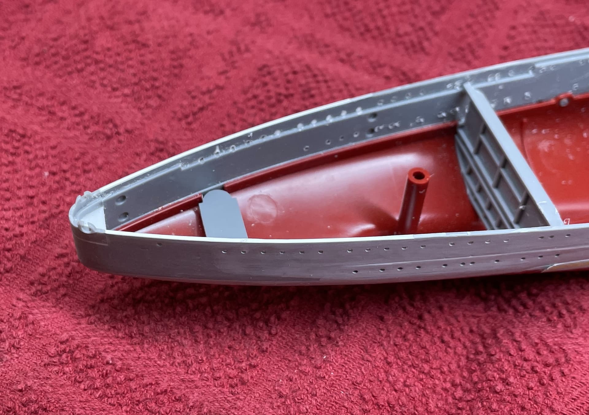
Overall the dimensions of the ship are quite accurate; however, I did discover one error made by Tamiya. The top edge of the tip of the stern should be 4.9m (0.551”) above the designed waterline, or 10.4m (1.170”) from the elevation of the keel. However, on the kit this distance was about 0.015” too short. I quickly corrected this by sawing off the tip of the stern and adding a shim of styrene. I then added styrene sheet to the tapered edges of the hull at the stern and sanded these flat, as shown below:
The amidships and stern portholes were drilled using the methods previously described. Figuring out porthole positions was easy, but I did run into a different issue. It turns out that the template I had been using to mark the position of portholes was oversized by about 0.2%. This might sound like a negligible error, I certainly thought so; however, it really added up since the datum I was using was the front of the ship. By the time I had reached the stern portholes the total error had compounded to 2mm, or about the distance between two portholes. Luckily I caught on to this before drilling the stern portholes, in time to create improved templates to correct the mistake.
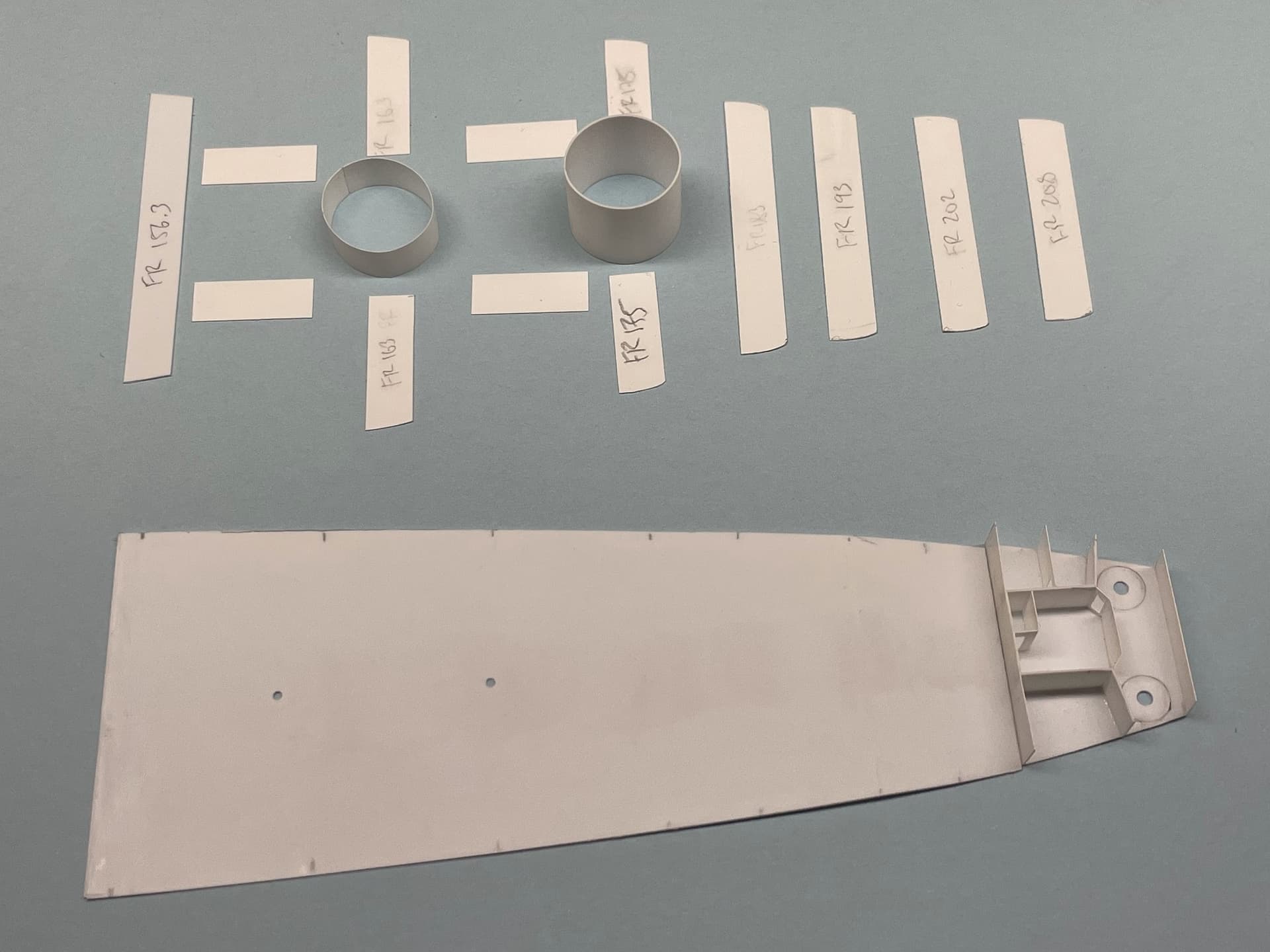
Four Weeks Ago – Frame Template Creation
These improved templates were a whole other rabbit hole, but the result was a neat set of tools. These frame templates make it possible to mark the location of any frame on the ship! Since portholes fall between the frames, this template was also useful for checking their placement.
The first obstacle in creating frame templates was determining the frame spacing for each section of the ship (bow, forward magazines, boiler rooms, engine rooms, aft magazines, stern). I used the 1940 Mikuma plans as my primary source for this task, as well as the overall length (200.6m), engine room length (33.9m), and boiler room length (44.24m) published by L&W, to accurately define a global coordinate system for the ship. The frames were drafted in CAD and plotted in 1/350 scale. This paper template was glued to thick cardboard sheets, contoured to match the curve of the hull, and then fastened to wooden bars for increased rigidity.
Two Weeks Ago – Correcting a Warped Keel
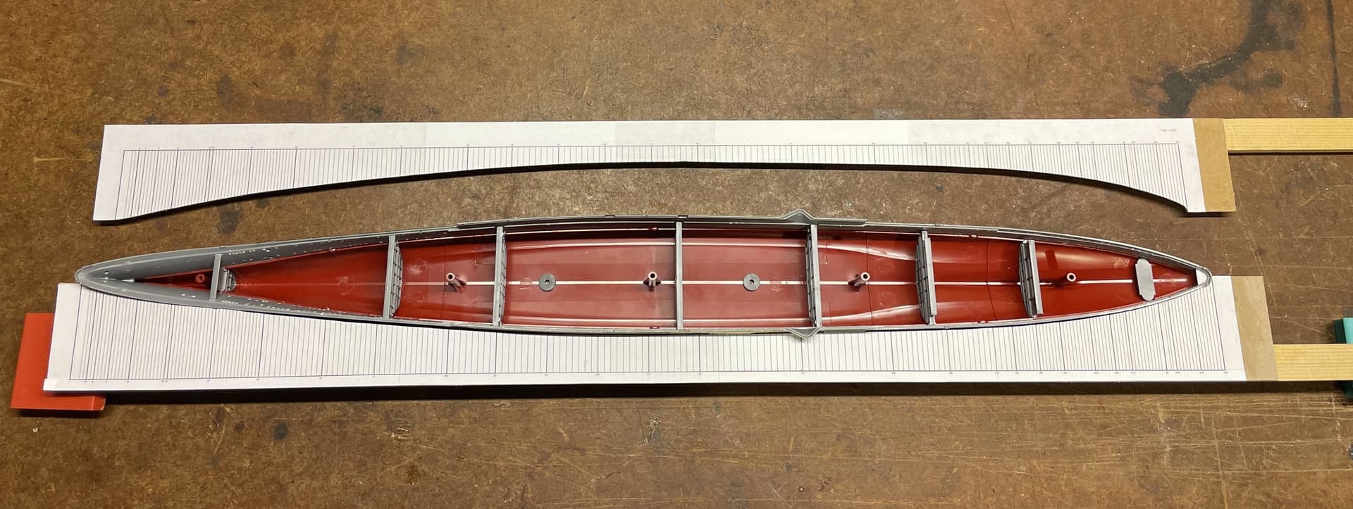
I have been aware of a significant warp in the hull for months, but was not immediately sure how to begin correcting it. When the model is set on a flat surface, the keel at the bow and stern of the ship both rise about 0.080” (2mm) above the surface. The red lower hull piece must have been warped from the factory and it just took a while for me to notice. This was really bothering me, especially since the warping spread through subsequent parts, resulting in warped upper surfaces as well.
I have been pondering this problem since August, and recently decided it was time to attempt a fix. I considered several potential solutions, from using heat to relax the plastic to installing a sort of truss rod. Finally, I settled on building an internal brace to force the keel flat from the inside. I am a bit limited on what I can build since I don’t have a mill, so working around this, my design was based on materials sourced from the local hardware store and the hand tools, drill press, and lathe I have in the shop.
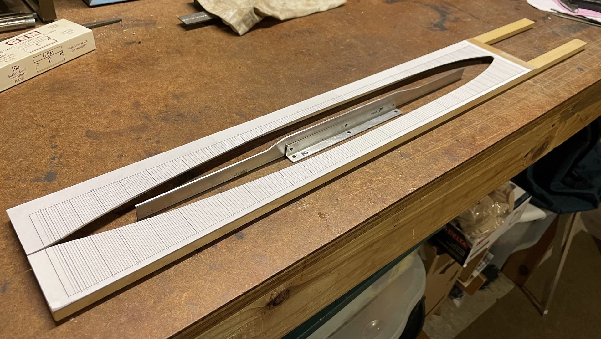
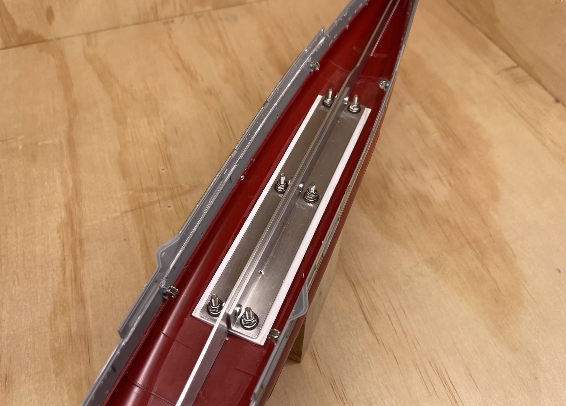
The idea was to fasten a tall, thin beam of aluminum securely along the internal surface of the ship’s keel, which would force the bow and stern flat. The selected beam was 0.058” thick and tall enough to be fairly rigid under bending stresses. This thickness of aluminum was chosen since it would fit into the narrow slot that runs along the center line of the hull interior; additionally, it was thin enough to shape by hand. Using approximate design loads, I double-checked the maximum theoretical bending deflection, shear stress, and normal stress the beam would experience and found these to be within acceptable limits. L-channels were used to fasten the beam, and countersunk screws clamped these channels into the ship hull. As the screws are fully tightened, the keel is straightened and held firm.
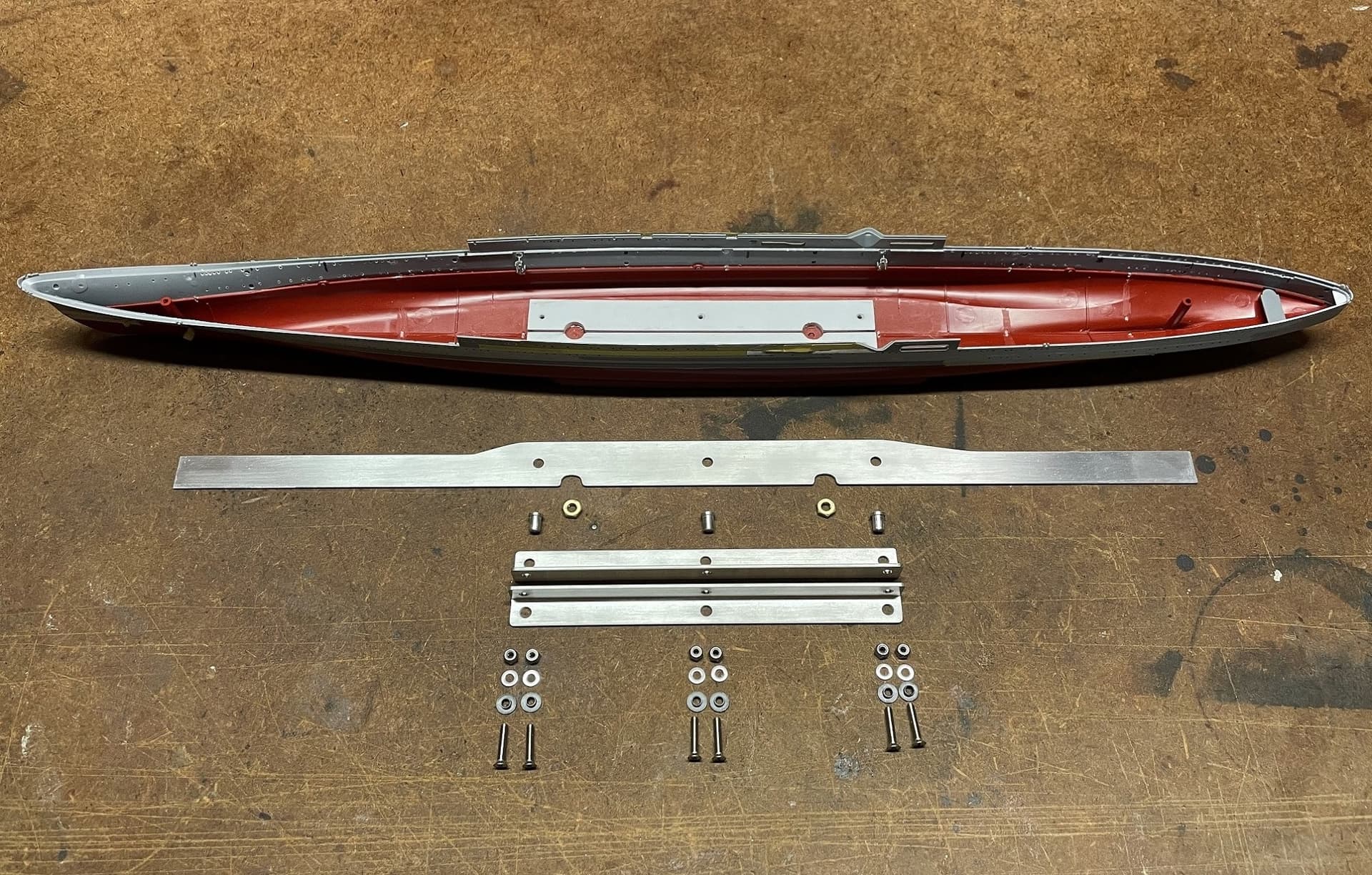
A result of this added hardware was the need to remove and reconstruct the existing internal bracing. The bulkheads and columns were removed to be replaced later. Plastic pads were cut and installed as a foundation for the aluminum channels. These pads were planed at 7.5 degrees to match the hull bottom amidships.
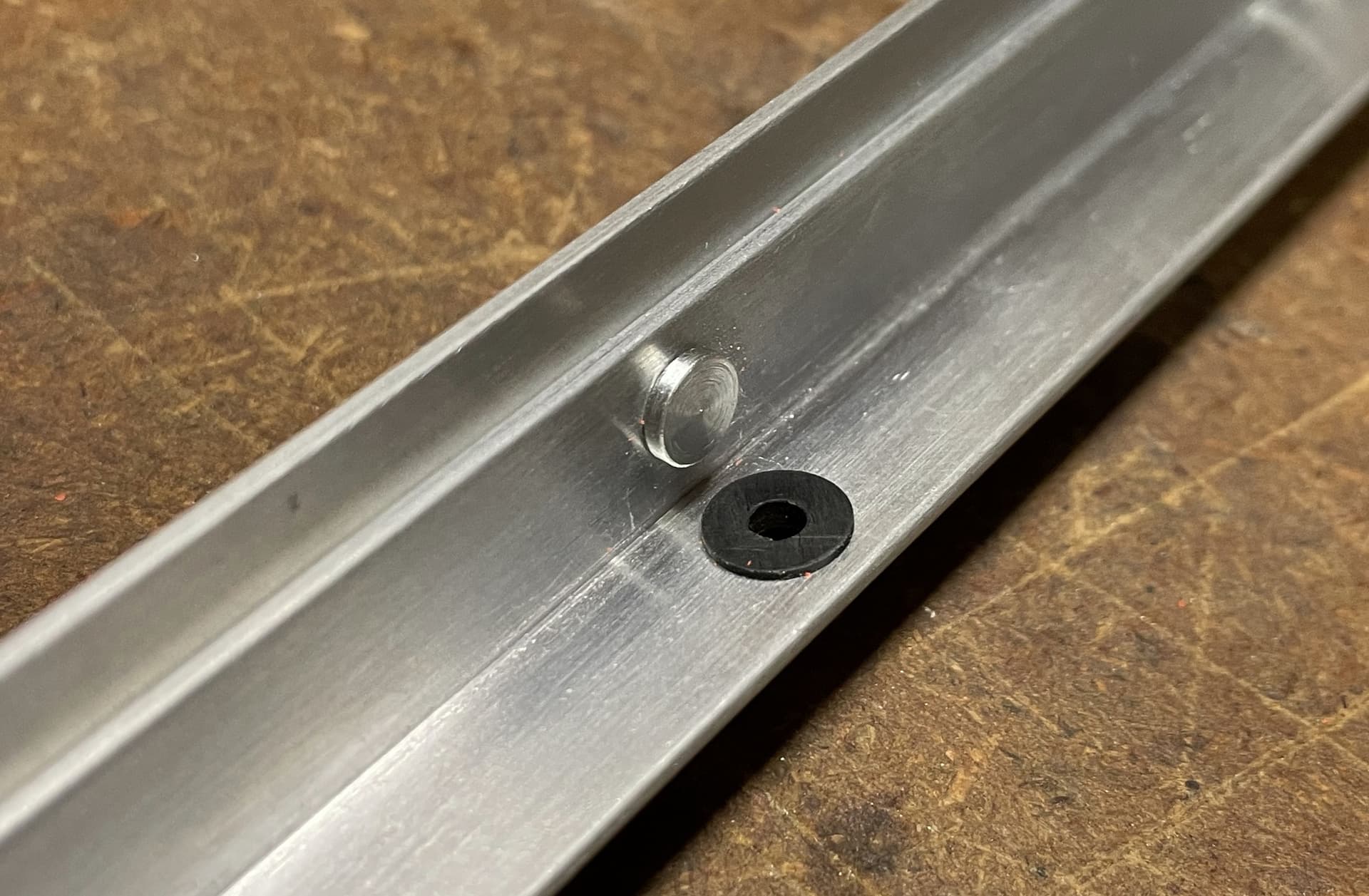
Since I live in a wet climate and I want to be able to wash the model throughout construction, extra care was given to eliminate risk of corrosion. I turned bushings from acetyl to isolate the stainless steel hardware from the aluminum, and made aluminum pins to fasten the channels to the beam. Ahh yes, over-engineering at its finest…
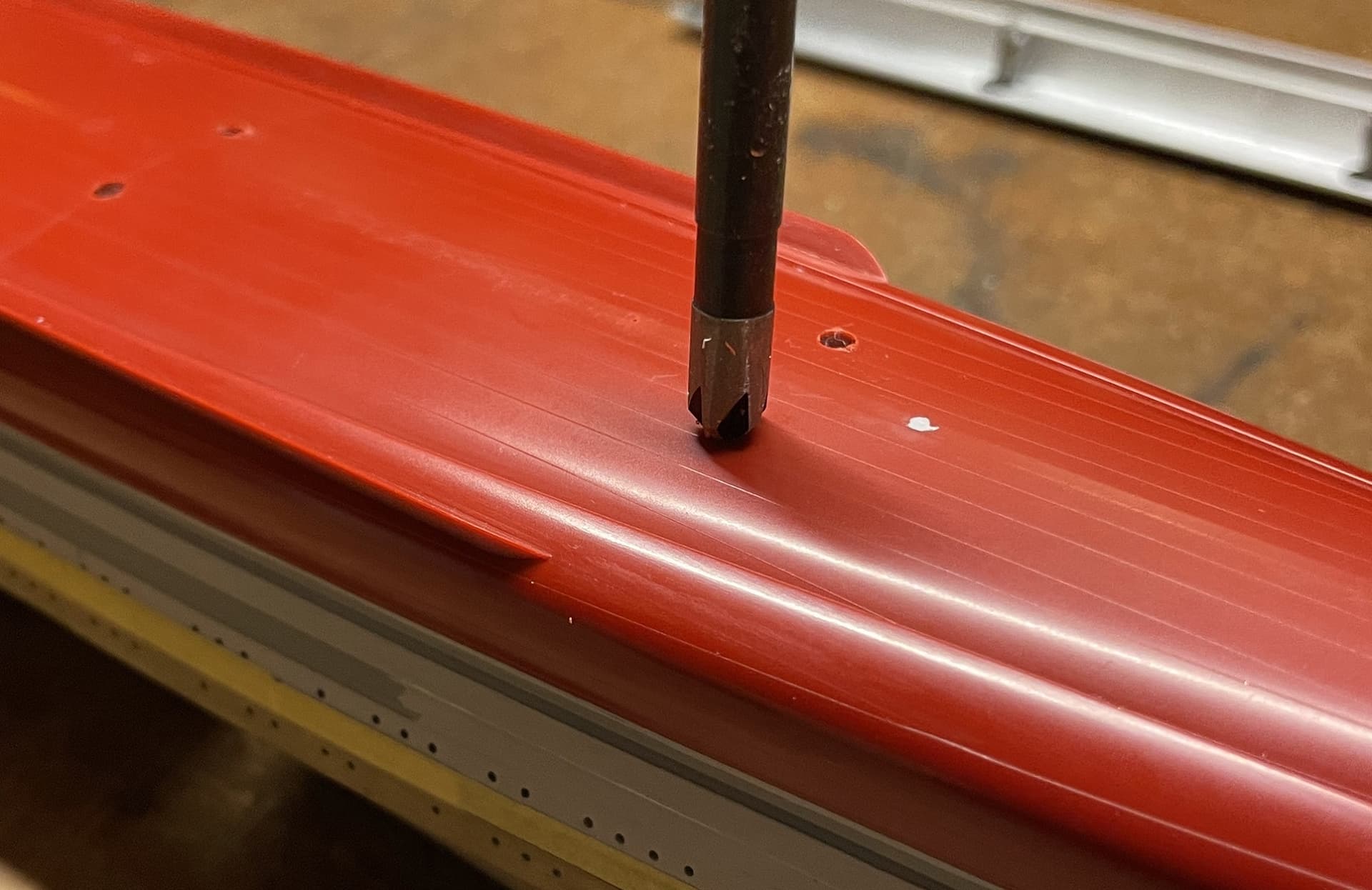
Countersunk clearance holes were drilled through the hull bottom for six screws to secure the internal brace to the hull. Yes, I know there weren’t holes here on the ship  they will be plugged, sanded, and plated over once the screws are fastened in place.
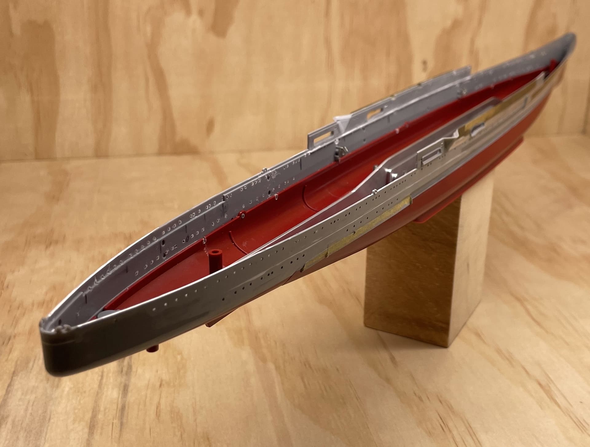
Here is the final result. It’s tricky to capture a before and after of the keel warping in a picture, so I didn’t. You’ll have to just take my word for it that this worked beautifully. The hull is rock solid, and the keel is straight.
Anyway, sorry for the long delay with the update, hope you enjoy.

Marty
10 Likes
Tremendous effort on your part Marty - alloy keel beam in particular. Well done .
Cheers - Richard
2 Likes
WOOOOOOOW!!! 


2 Likes
Marty,
Well done on correcting the hull warp, I wish I had the means to come up with repair method you chose. Thanks for the update.
Mark 
2 Likes
Thanks all,
Yeah I got a little carried away with this one, but I’m back to more traditional realms of modeling.
Up next the bow portholes will need a few tweaks to update them to 1942 positions. Then I will begin to tackle the hull plating and panel lines. I’m going to continue to experiment with a mix of these methods to replicate the individual hull plates/panel lines:
-
Brass sheet: for lap-jointed strakes
-
Raised weld seams via masking tape and spray primer: for welded areas of the bow and stern
-
Engraved panel lines: for the remaining strakes
Until next time,
Marty
5 Likes
Brilliant problem solving! Glad to see the update. Thanks Brother.
1 Like
Great work and very good progress & problem solving!
Sorry for my long absence, I’m in and following!
Cheers
Jan
1 Like
its beautiful so far, Is that block of wood the base!? very modern haha
Thanks hobbyish!
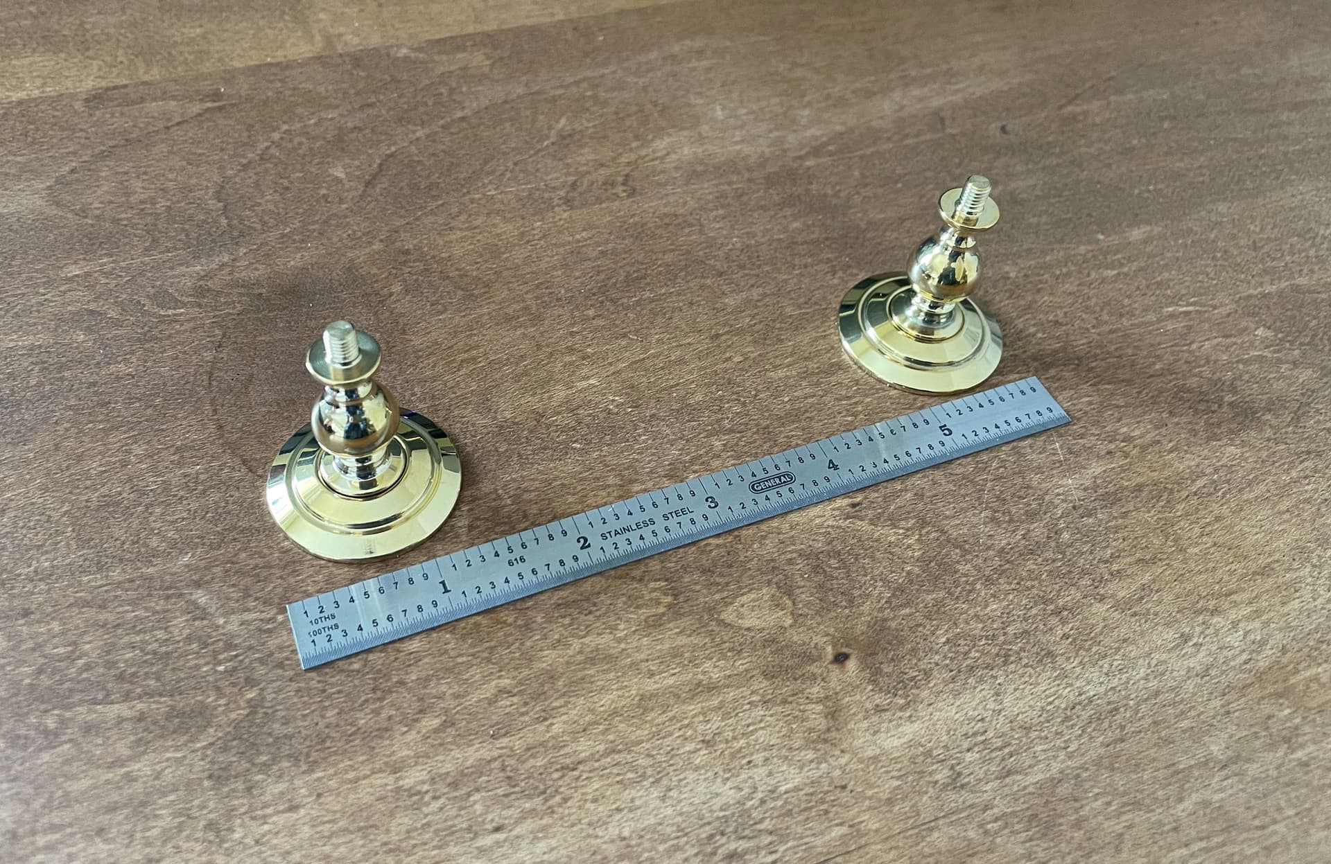
Base will be these Pontos 35mm brass pedestals. I didn’t mention it in the last post, but I already epoxied some 5mm brass nuts under the aluminum structure for mounting the ship. I will probably find a large plank of dark hardwood to serve as the base.
Still working as much as possible on the build, but it’s two steps forward one step back, as usual. I embarked on an exciting diversion from the plan stated above, and most of the progress is not photogenic at this point. I expect that an update will be ready in the next week or two.
Marty
7 Likes
I just found this thread. Mikuma is a favorite of mine so I will definitely follow along!
Bill
1 Like
Hey all,
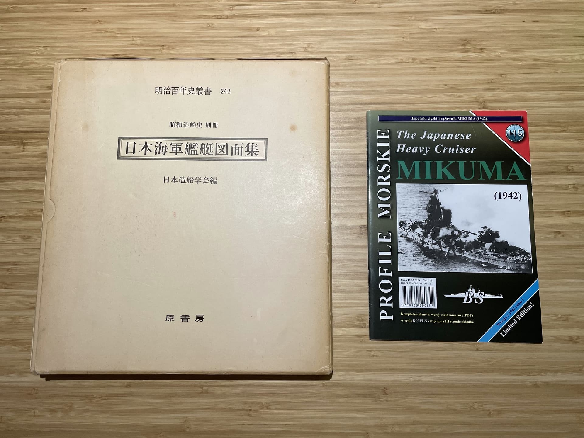
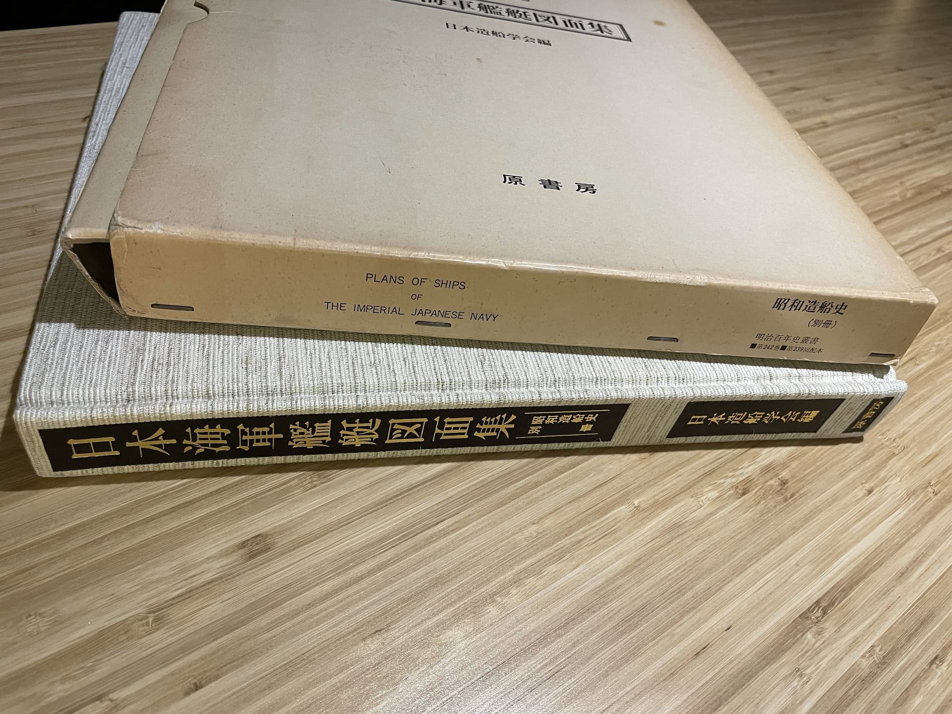
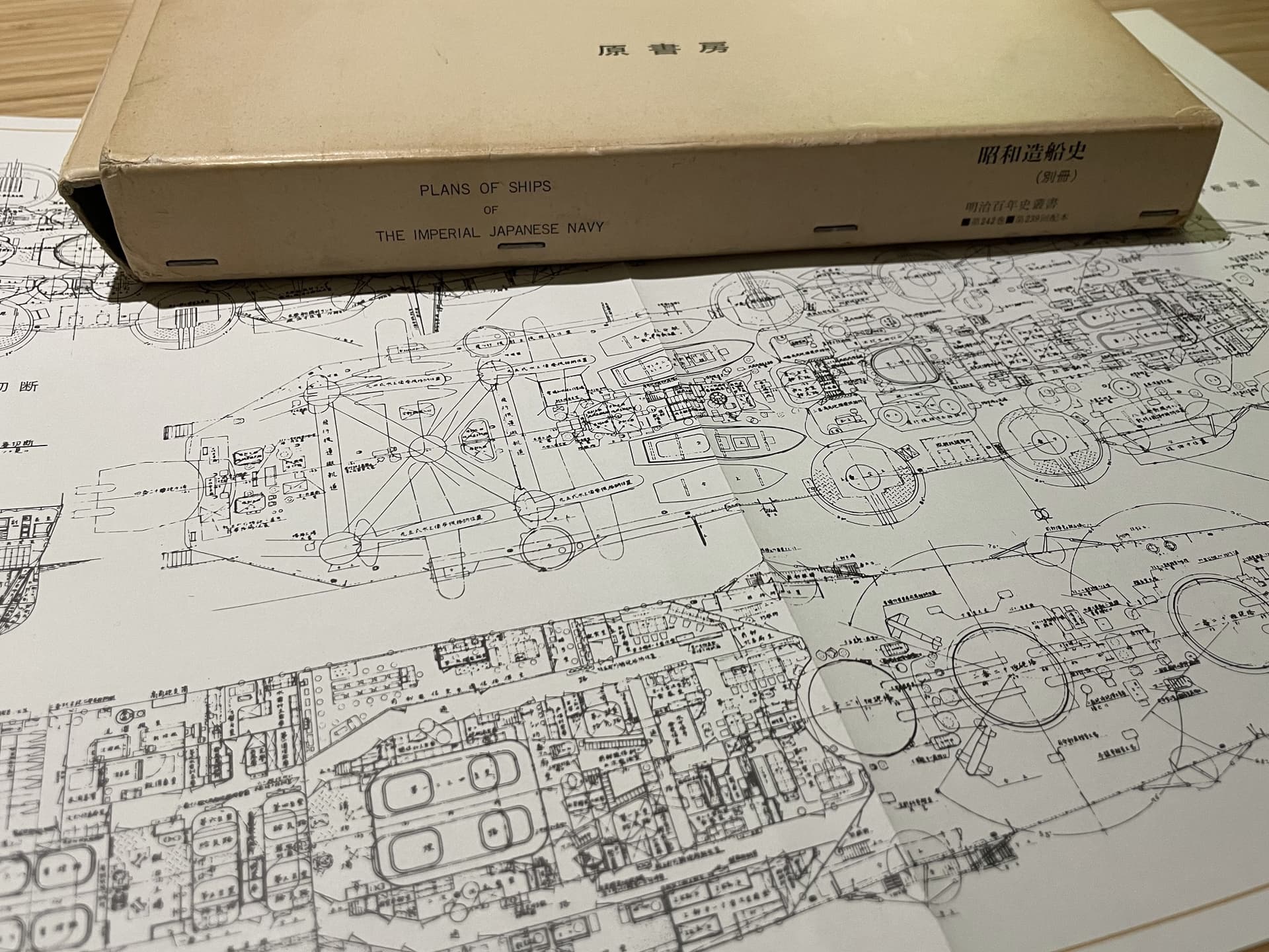
I took delivery of some additional materials. I’m happy to say that I finally managed to come by Plans of Ships of the Imperial Japanese Navy: History of Shipbuilding in Showa Era for a reasonable sum. Also the somewhat less illustrious Profile Morski 115: Mikuma.
As for Mikuma: it’s been a year since I embarked on this project, so I feel a proper update is probably overdue…
Despite my radio silence on the forum of late, I have been working steadily on Mikuma. Motivation to keep the blog up to date has been a little low due to personal time constraints and world events. Additionally, I had numerous delays over the past few months, waiting for reference materials and new tools to arrive. However, I think I am now ready to spill the beans on what I have been working on; I have started a tangential project that is really quite unnecessary and will probably increase the project completion time by at least a year. But, before you read further, just know that what I am attempting is more about the journey than the destination.
Where to begin…
Back in November I finished drilling the last portholes on Mikuma, and I couldn’t help but imagine how cool it would be to accentuate this detail by lighting the portholes on the finished model. As a warship, the lights would be blacked out most of the time during the war, but I reasoned that the ship could be represented in a home port shortly before the start of the war. Anyway, regardless of historical accuracy, it is a feature that will look cool and can be turned off at any time. So I bought some pico 3V LEDs from Evan Designs and started experimenting.
The obvious way to light the interior would be to place several LEDs inside an unpainted styrene tunnel running the length of the ship across all deck levels. These lights are surprisingly bright, and it would only take a couple to do the job. However, the truth is that I had been itching for an excuse to build out the basic interior compartmentation of the vessel ever since I came across deck plans for the ship. This desire must have been subconsciously influencing me, because I quickly became VERY carried away with this plan. I decided it would be more realistic to light interior cabins separately, running two or more circuits in order to achieve combinations of lighting conditions, such as: all lights on, all lights off, and lights in alternating compartments on and off. This would require many more LEDs, a much more complicated circuit, and light blocked (painted) bulkheads between compartments. So, for better or worse that is the plan I am working with.
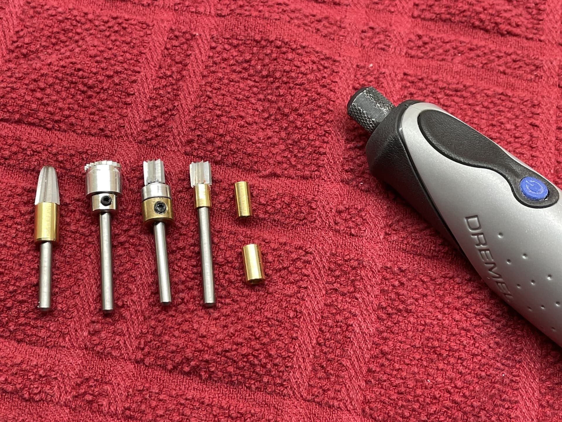
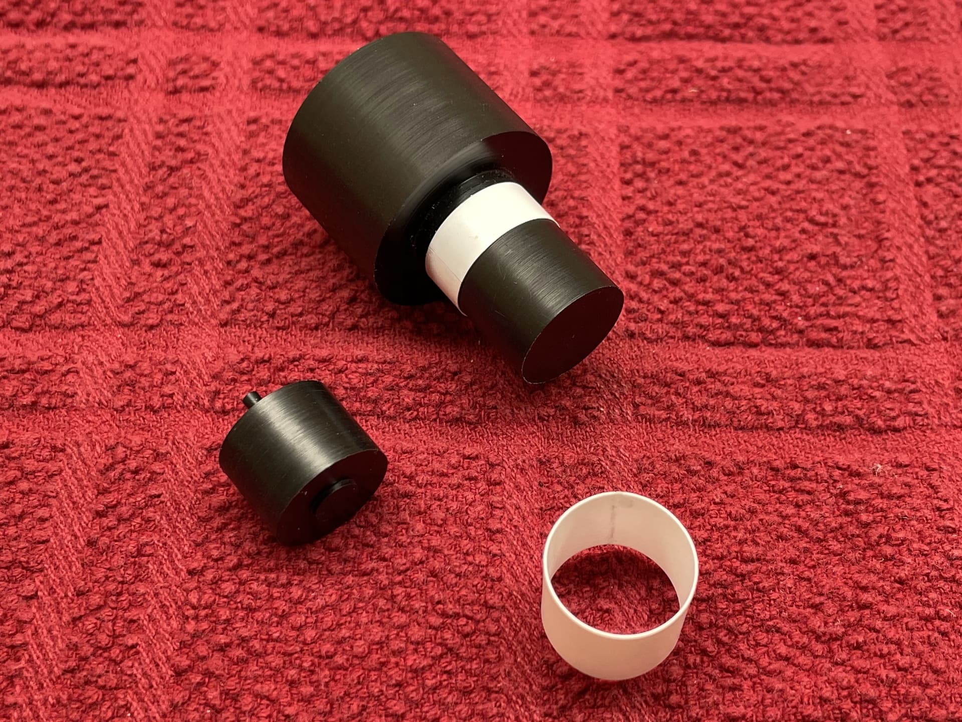
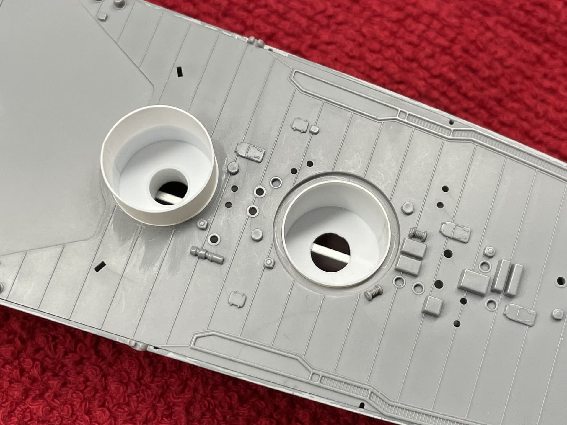
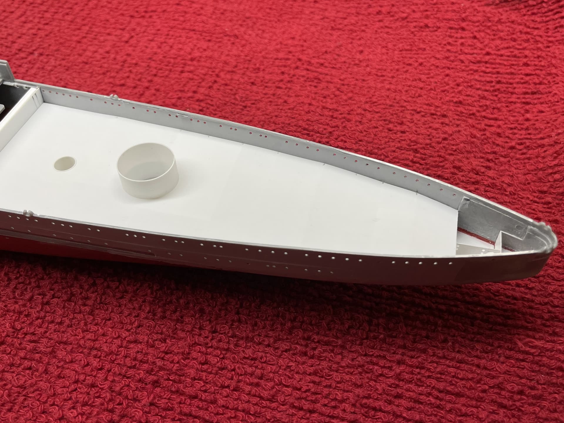
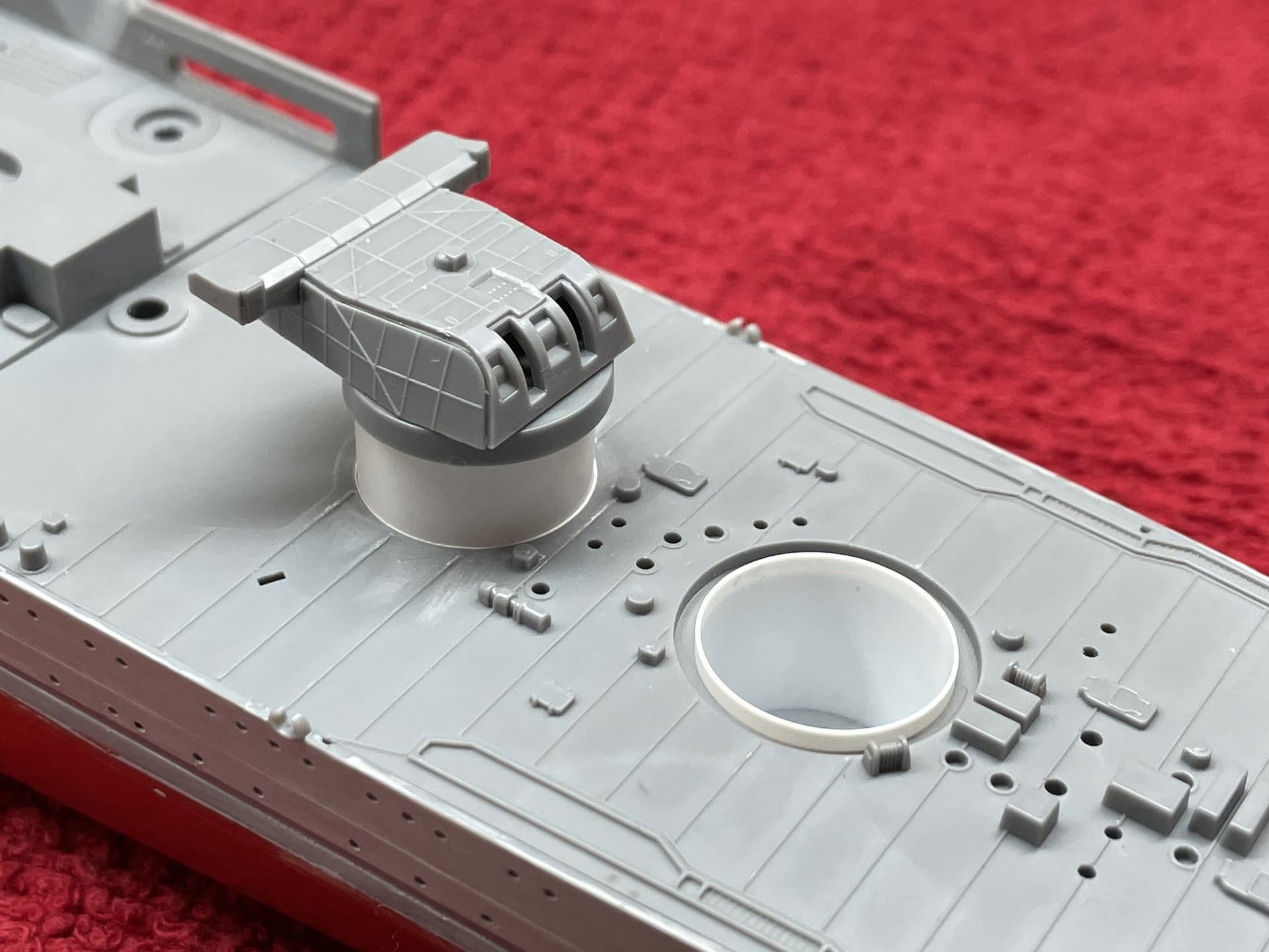
The first problem I encountered with lighting the ship was an effect caused by the thickness of the hull walls. The stock kit walls are about 0.060” thick on average, which leads the portholes to look less like holes and more like tunnels, especially when backlit. Eventually, I found a new tool to thin the walls evenly without damaging the kit. The Dremel Stylo is variable speed down to 5000rpm, and is small enough to hold like a pencil. With the goal of using the tool like a hand-held router, I turned a few bushings out of brass to help control the length and depth of cut. These bushings were oiled (free to rotate) and secured onto the cutter shafts with set screw collets.
In this picture you can see the routing set up that was used to make a precise undercut along the inner lip of the kit part. This cut maintained the original thickness of the top edge of the hull, so that the deck would still fit snugly in place.
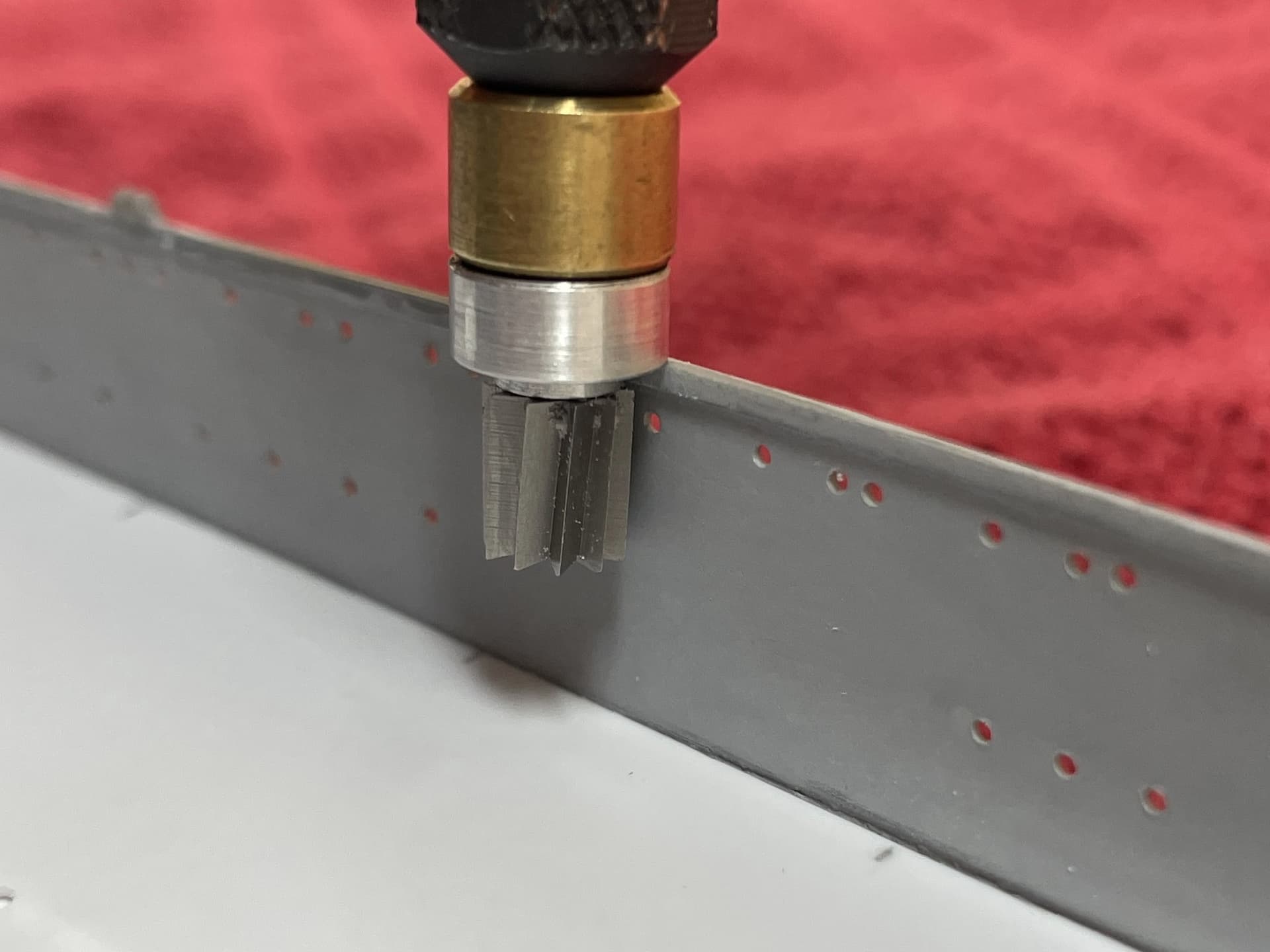
With this variety of cutting tools I was able to thin the walls of the kit from 0.060” down to 0.020”. This is about the distance (in scale) that the frames extend into the compartments of the lower and middle deck levels, but more importantly is about as thin as the walls can be without becoming too fragile.
Here is a comparison of the portholes when backlit. On the left: the original wall thickness, and on the right: the thinned walls. Excuse the yellow color of the lights; I will probably use warm white LEDs instead of yellow in the final circuit.
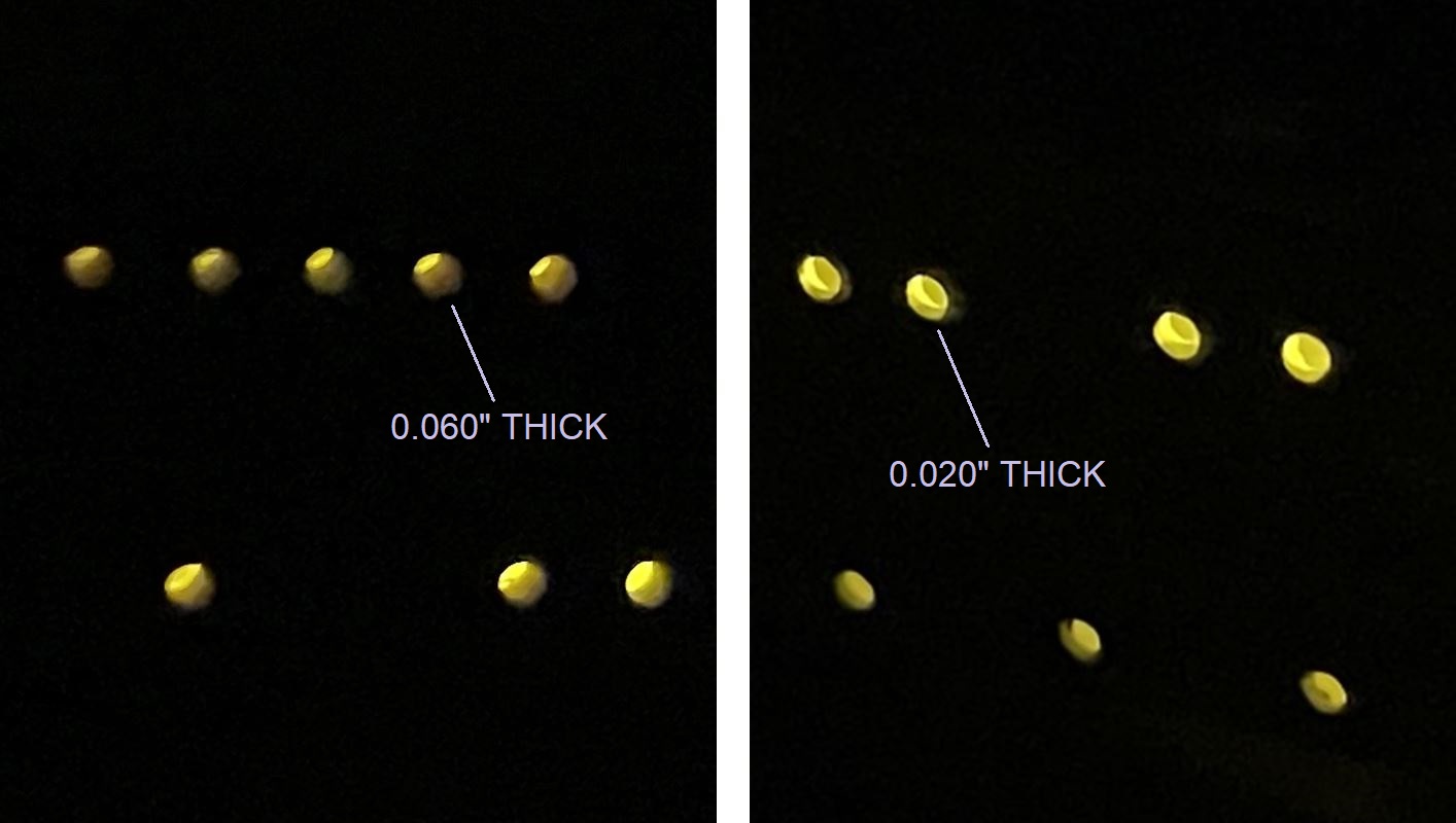
Kind of a subtle improvement, but that’s pretty much my MO. I’m happy with the result.
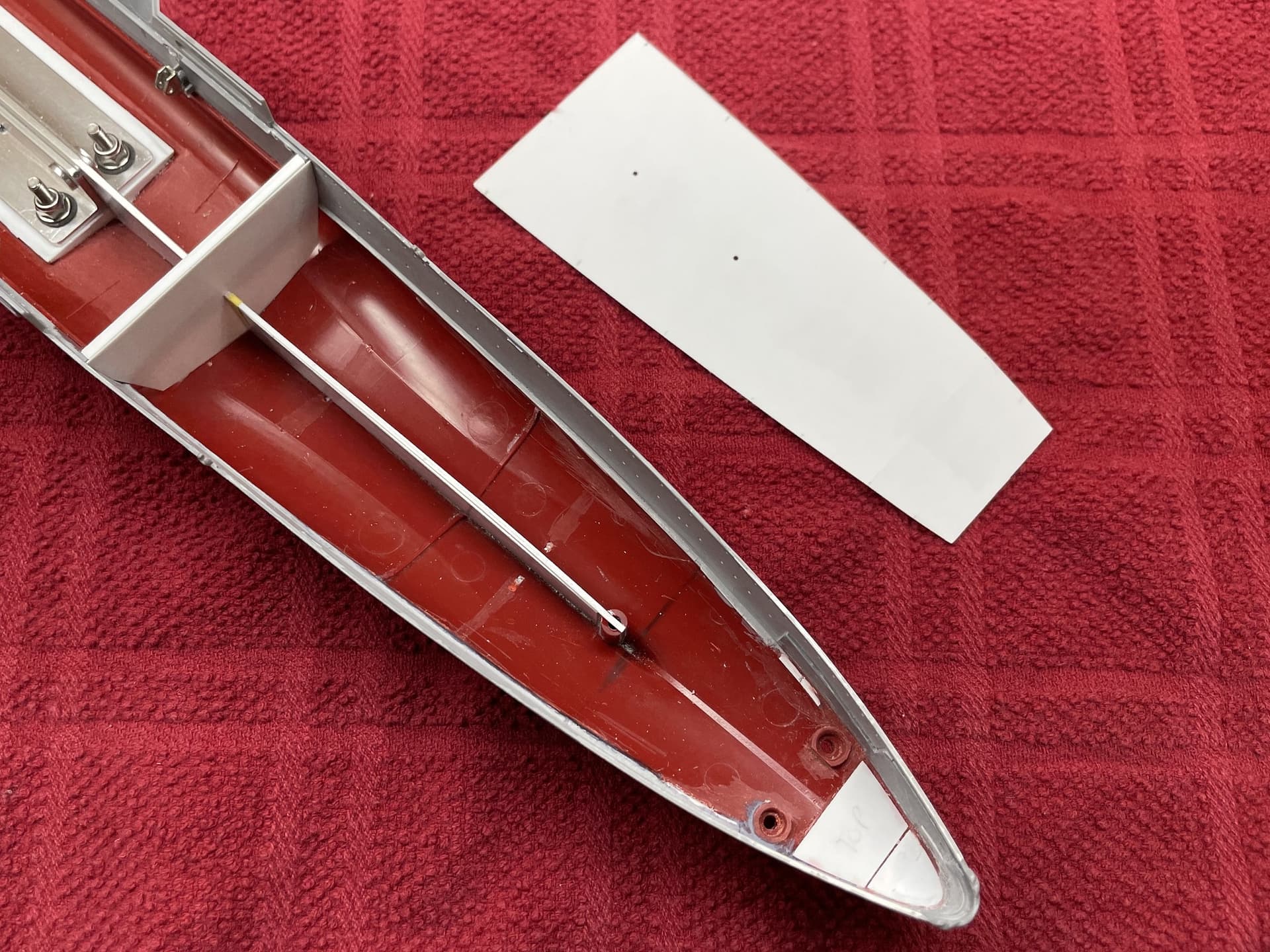
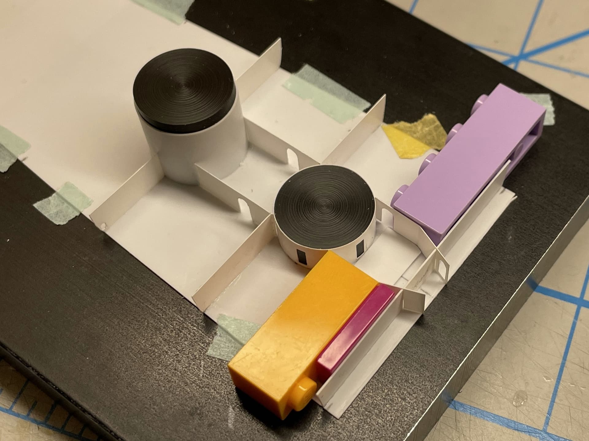
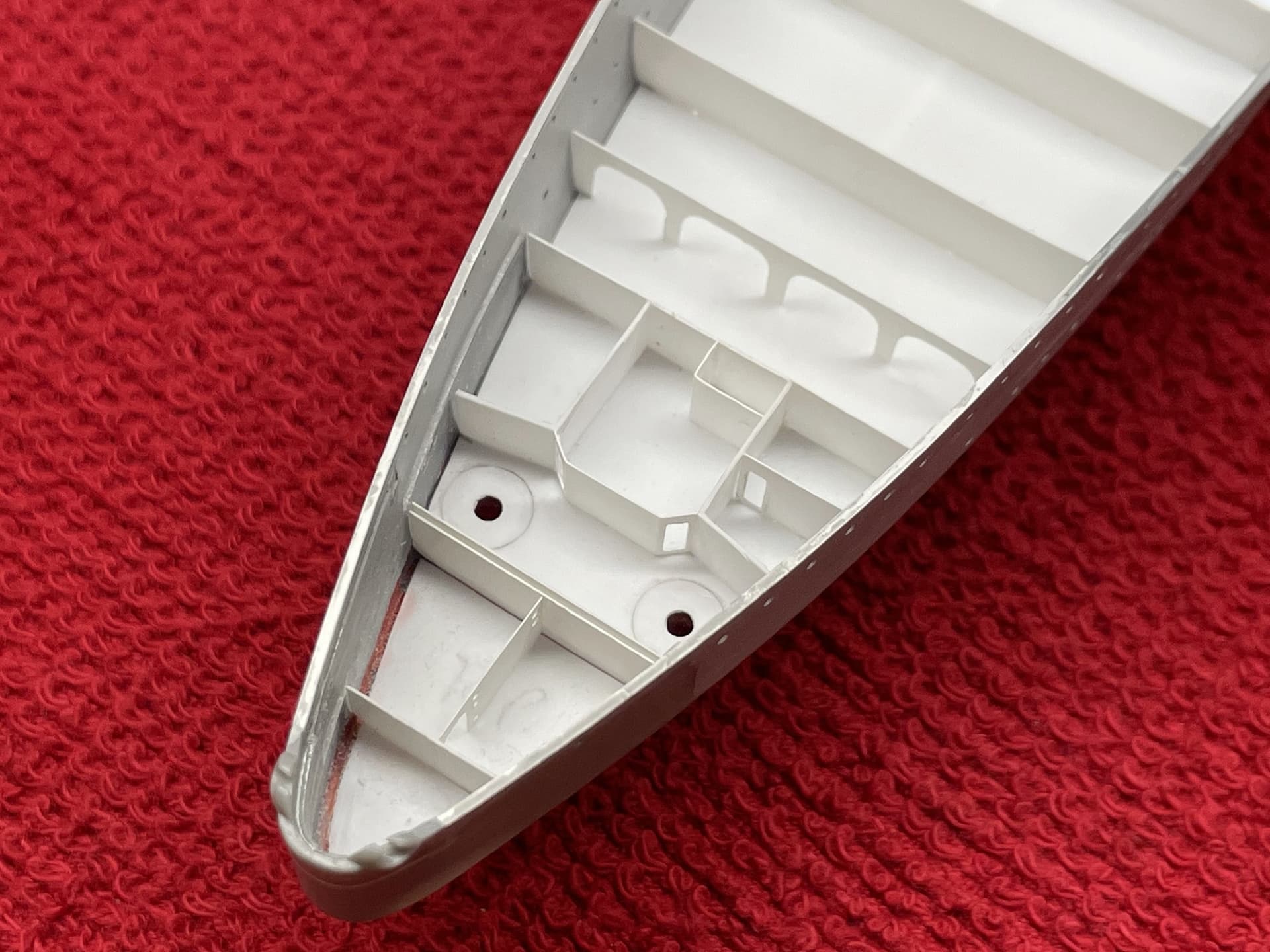
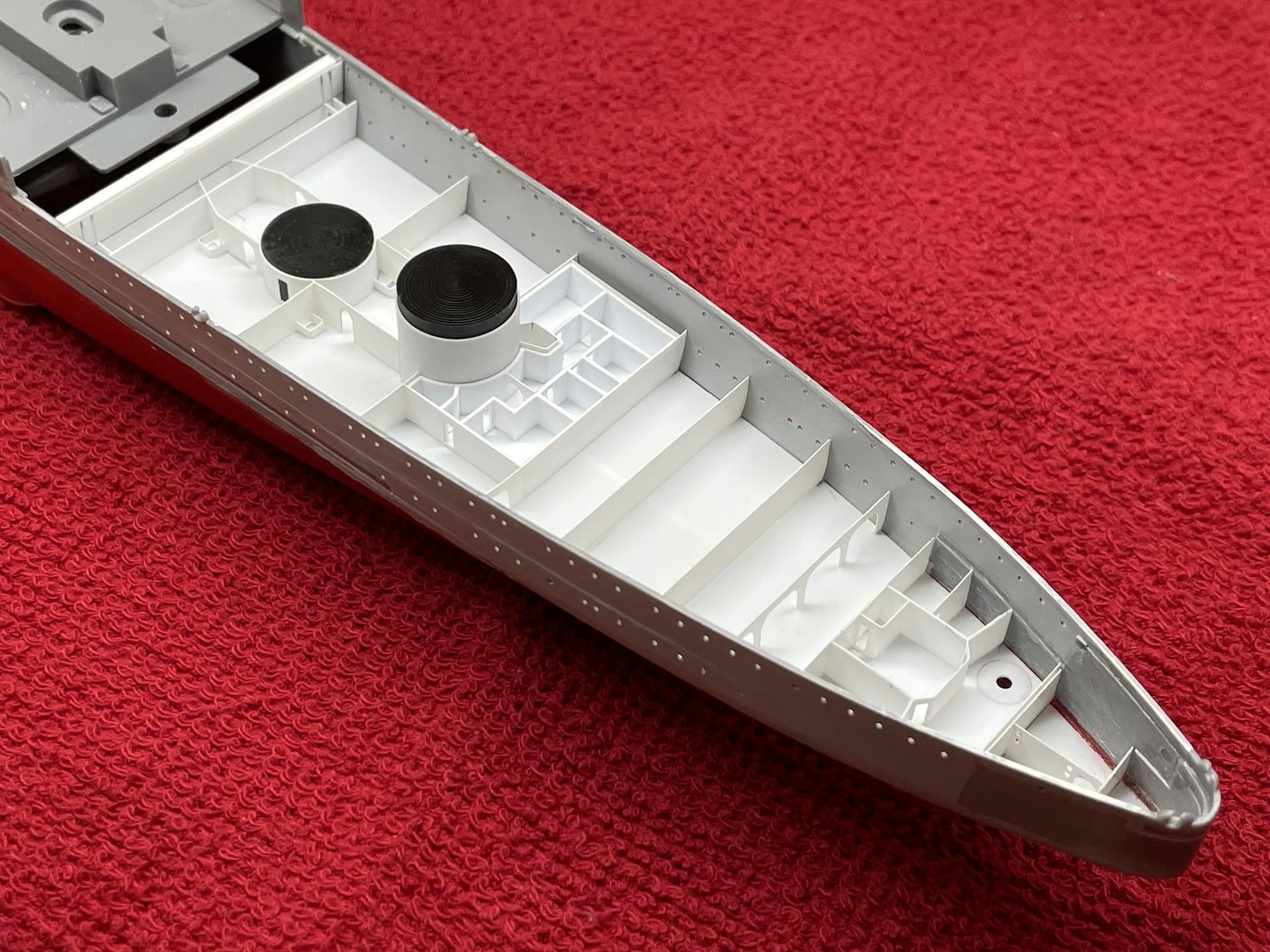
After the hull of the ship was prepared, it was time to begin scratch building the lower deck compartments. I started with the stern area around the steering and rudder room, then constructed the barbettes and crew quarters bulkheads. Most compartments were made from 0.005” styrene, with armored sections made from 0.010” styrene sheet. It would have been much easier to build everything from 0.010” styrene, but the scale effect I’m after would have been lost.
I turned acetyl rod into a tool to help construct the barbettes and accompanying cylinders of various dimensions. Other tools were made to help locate holes that needed to be drilled through the lower, middle, and upper deck pieces.
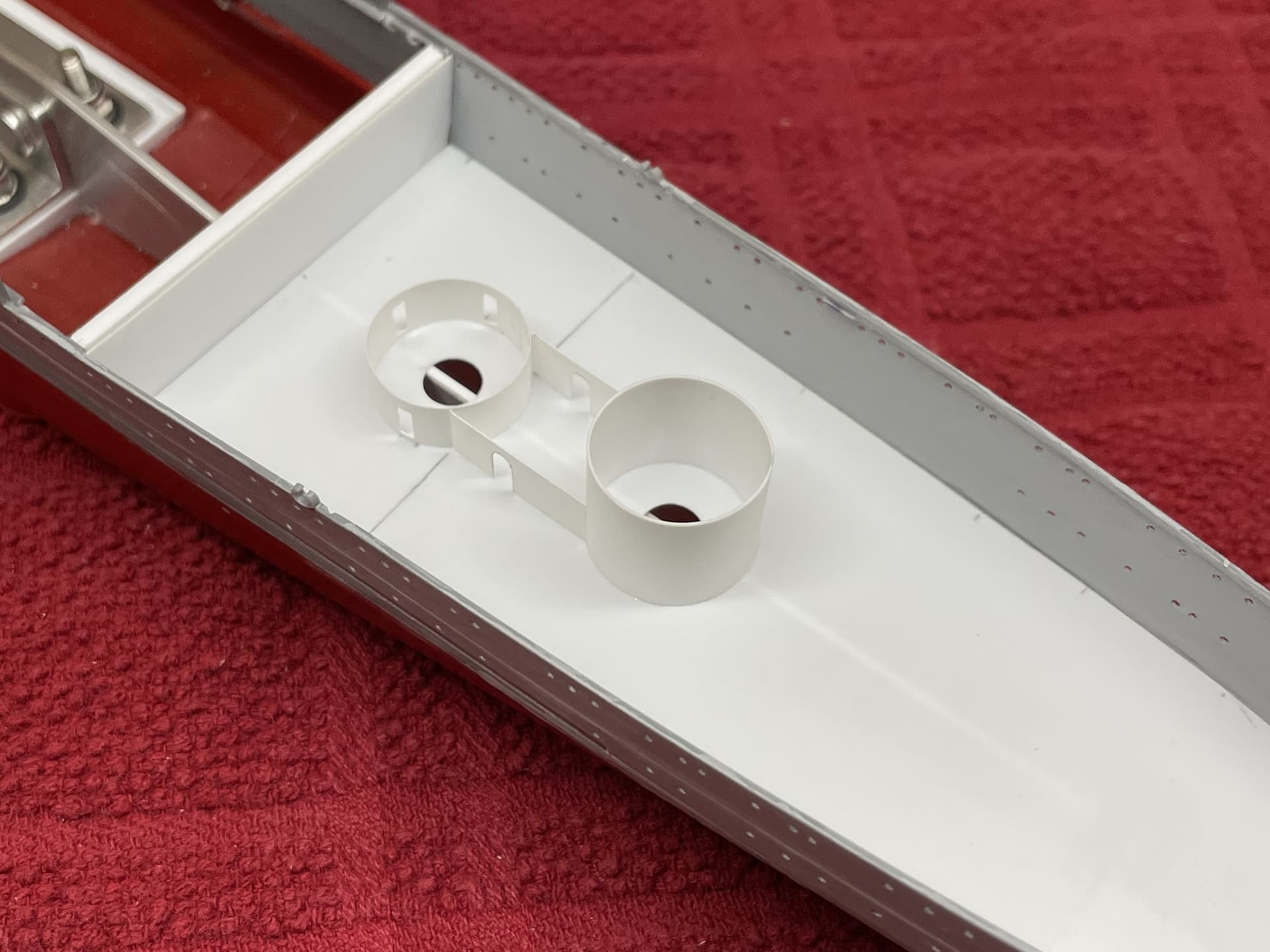
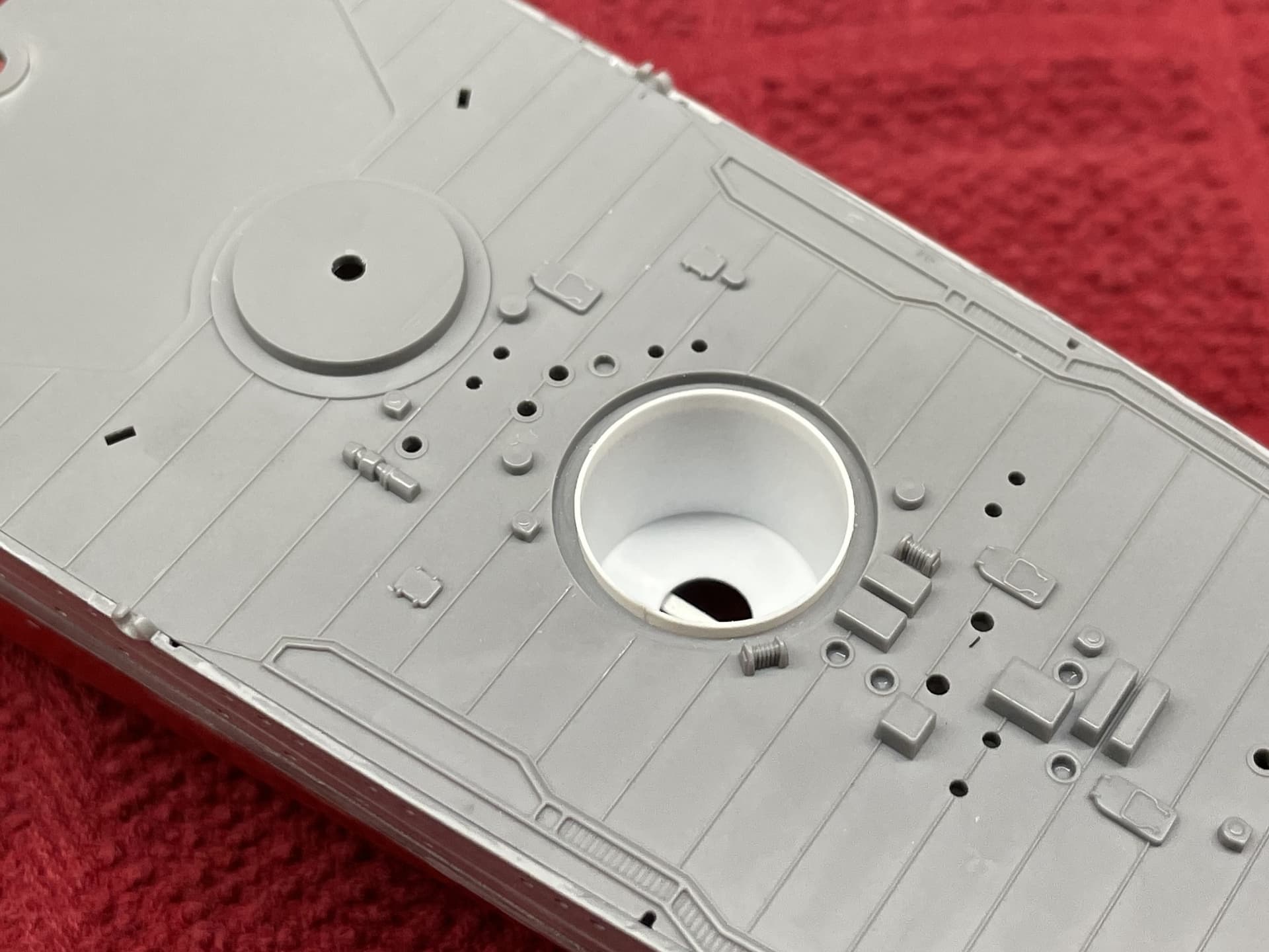
Some in progress pictures show the methods of construction. Dimensions of compartment walls were determined from a 1/350 print out of the Suzuya Lower Deck plan. All parts were fit checked in place before being cemented with a touch of Extra Thin. I used the good old LEGO tooling method to keep angles square.
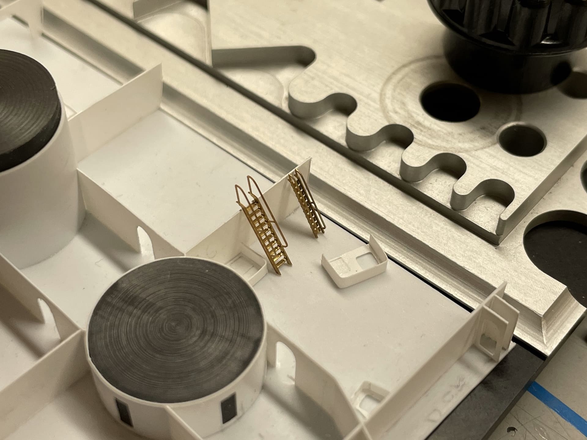
A full interior would be a truly insane amount of work to complete, and would be lost forever once the model is closed up, so I am limiting myself to simple compartment walls, doorways, and ladders. This work will be lost eventually too, but at least I can take pictures to document the effort. It’s hard to explain, but much of my fascination with the complexity of the ship at this scale has to do with figuring out how crew would have moved about. So this level of detail allows me to satisfy that interest.
Here is a look at the refrigeration compartment. Note the thickened insulation in the walls. The layout of this area was based on the deck plan for Suzuya, with a few alterations, as the two section views I have for Mikuma show slight differences.
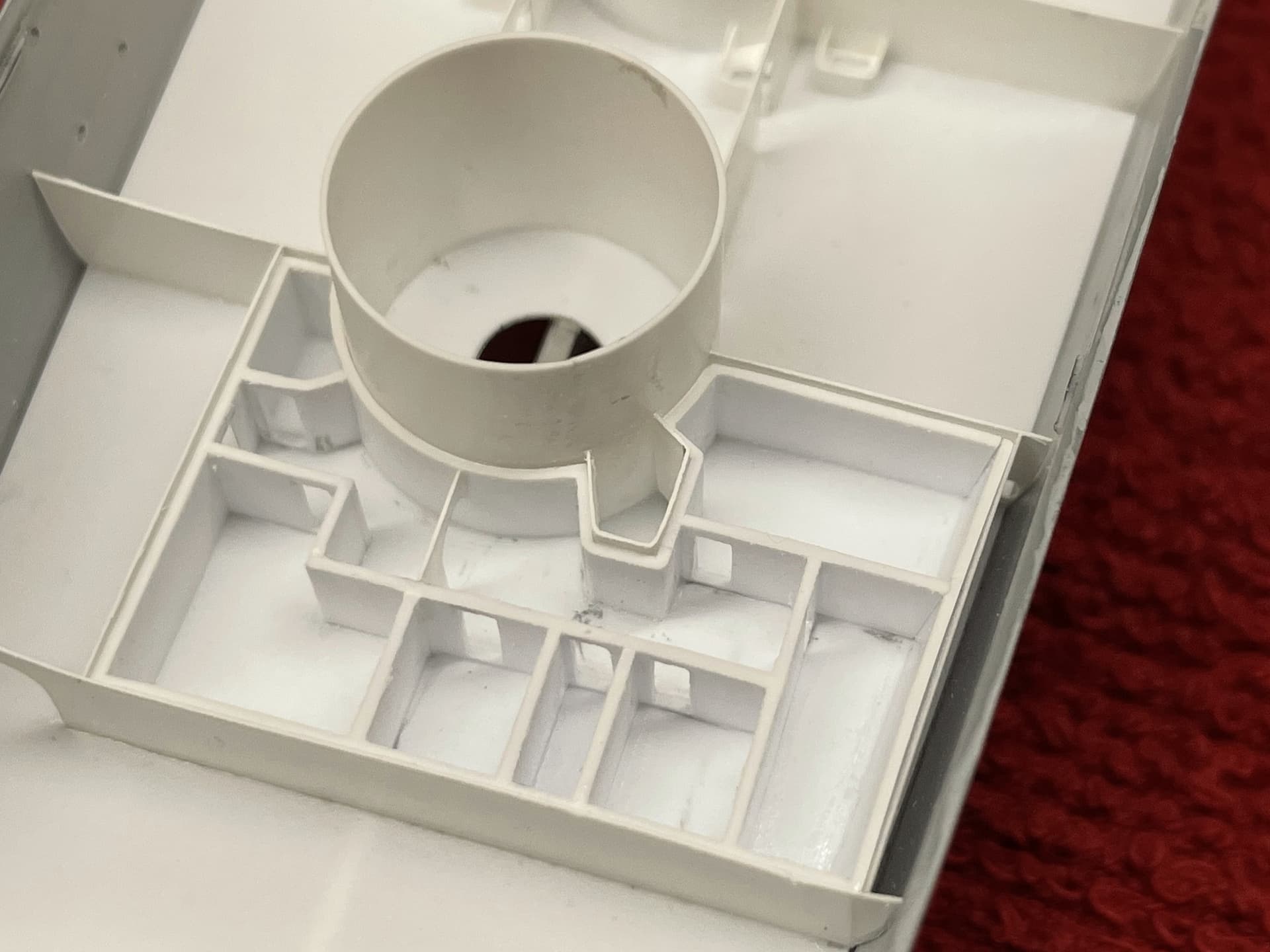
The stern region of lower deck level consists of the armored steering and rudder compartments, surrounded by storage rooms.
This is the current state of affairs. The aft lower deck level is complete, minus painting and wiring. The middle deck subassembly will be constructed similarly, and both subassemblies will be painted and wired separately and glued into the hull only once the hull and all decks and interior spaces are complete (probably years from now). I have not yet decided to what extent I would like to add photo etch doors and ladders. Also, although I have ideas of how to paint and install LEDs to the deck subassemblies, I have yet to actually test them out, so more on that coming up.
Next I will begin adding the bulkheads to the middle deck level, the deck of which has already been constructed. As much as I would love to build out the magazines, boiler rooms, and engine rooms, I will not be doing so, as the aluminum support structure I added to flatten the keel conveniently renders accurate scratch building in these areas impossible.
There is much more to say and show, but this post is already quite long so I will leave it there for now. Hope you all can excuse the long delay in getting this update out. Until next time! ![]()
Marty
9 Likes
Hi Marty,
Bit late to the party on this one, but I have to say, Great work.
Cheers, Si
1 Like
Glad to see this update Marty - always interested in your first class efforts .
Richard
1 Like
Holy Moly! That’s going above and beyond, Marty ![]()
1 Like
Sweet!
Mark ![]()
1 Like
Thanks all!
I’ve been having a blast with the scratch building. It has been a fascinating learning experience deciphering the plans and reverse engineering the compartments of the ship. Besides my bourgeoning interest in the mechanics of warships, my other source of motivation in bringing the interior spaces to life was to cast light on these less often shown details. Glad you are all enjoying!
Marty
3 Likes