Yeah just look at me, already a shrivelled husk and this one’s positively dessicating me. Gimme a break, what “fake tool rack”? I see no fake tool rack. But seriously how lucky are we Nick’s chosen this forum to make us consider changing to macrame blow our minds? ![]()
6 Likes
On one hand, glad you guys are liking the progress! on the other, now the pressure is on to both not screw it up, and to actually finish! ![]()
![]()
And to finish, at least this building, is what I want to do! While I recognized at the outset this would be a challenge, I wasn’t as tuned in as I should have been to exactly how much work this would be.
All of the super clever “yes, it will be board on board, weathered to an equal level, and square, and plumb, and look right, and get some nice detailing, and on and on” - yeah, a very good idea…
Well, it might be a good idea, but it takes a lot of steps, materials, and sequencing to get to go together. The good news is I’m still making headway, and went a ahead and forced myself to make more headway and not fuss around ponder about it - unlike this verbose posting ![]() no, out came the tools, on went the stereo, and away we went.
no, out came the tools, on went the stereo, and away we went.
First up, getting the rest of the addition built:
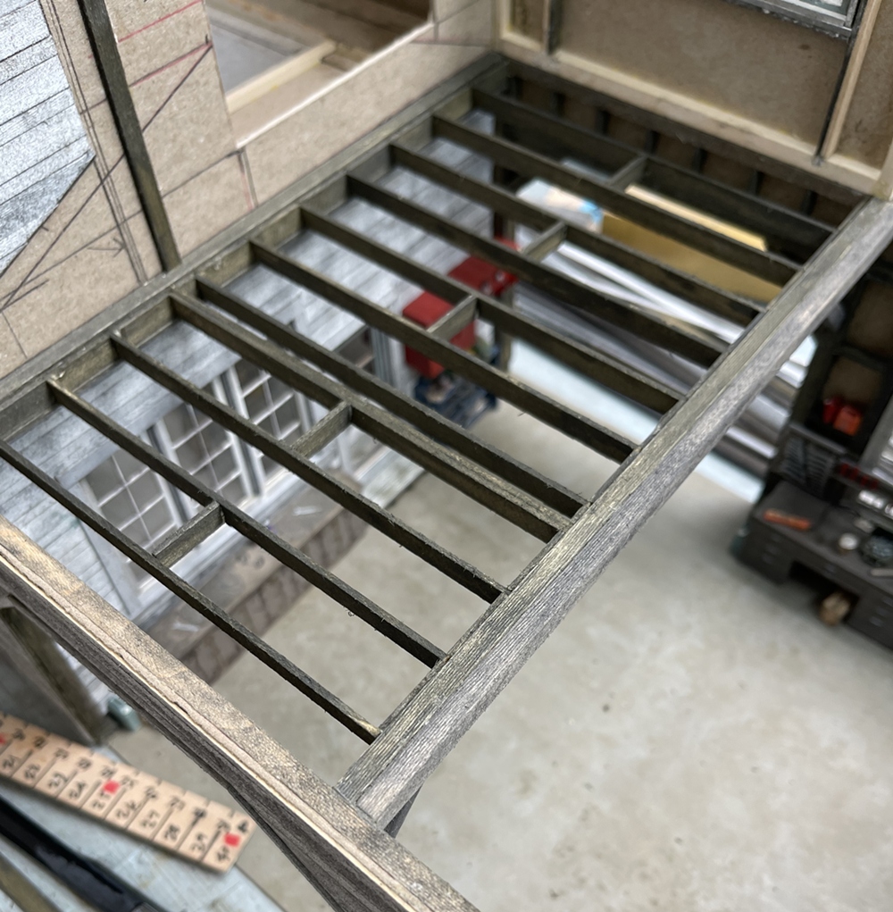

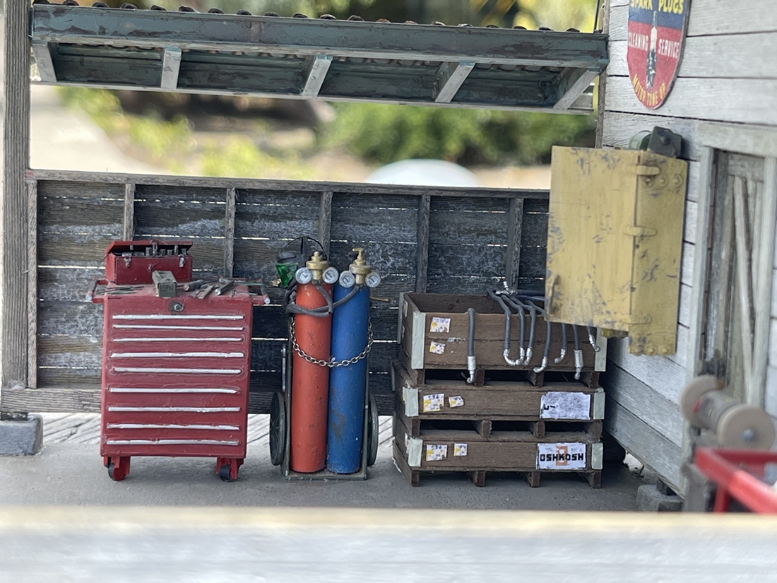
As “the addition” is built over the shop, the floor joist will be visible, so no cheating with just a chipboard sheet for flooring. And, back to sequence, while the shop area will be visible from many directions, the more closed in it gets, the harder it will be to fit my hand in to install whatever I want to be visible in the there. So, before the floor joists went in, cabinets and odds and ends were installed. And while at it, in went the rest of the shop tools etc:
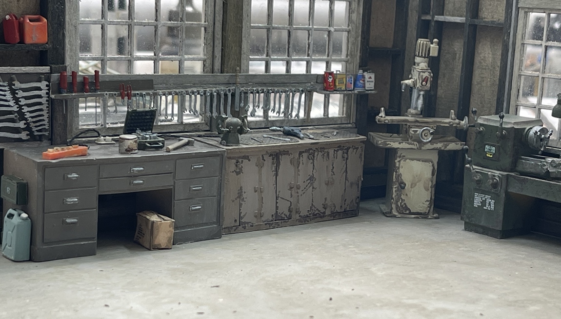


The benches and tools you see are a mix of old repurposed parts from a now derelict project modified to fit, and new/scratch parts - the goal being to make them look like they belong together, and fit in the shop. Here’s a tip, the tall narrow doors in the two brownish benches are supposed to be used on super detailed, HO scale locomotive long hoods - they are cheap and have nice detail, so are perfect here ![]() Most of the parts scattered about are remnants from old kits and left over PE just painted in neutral colors and weathered that look about right.
Most of the parts scattered about are remnants from old kits and left over PE just painted in neutral colors and weathered that look about right.
With this done, back to the addition:


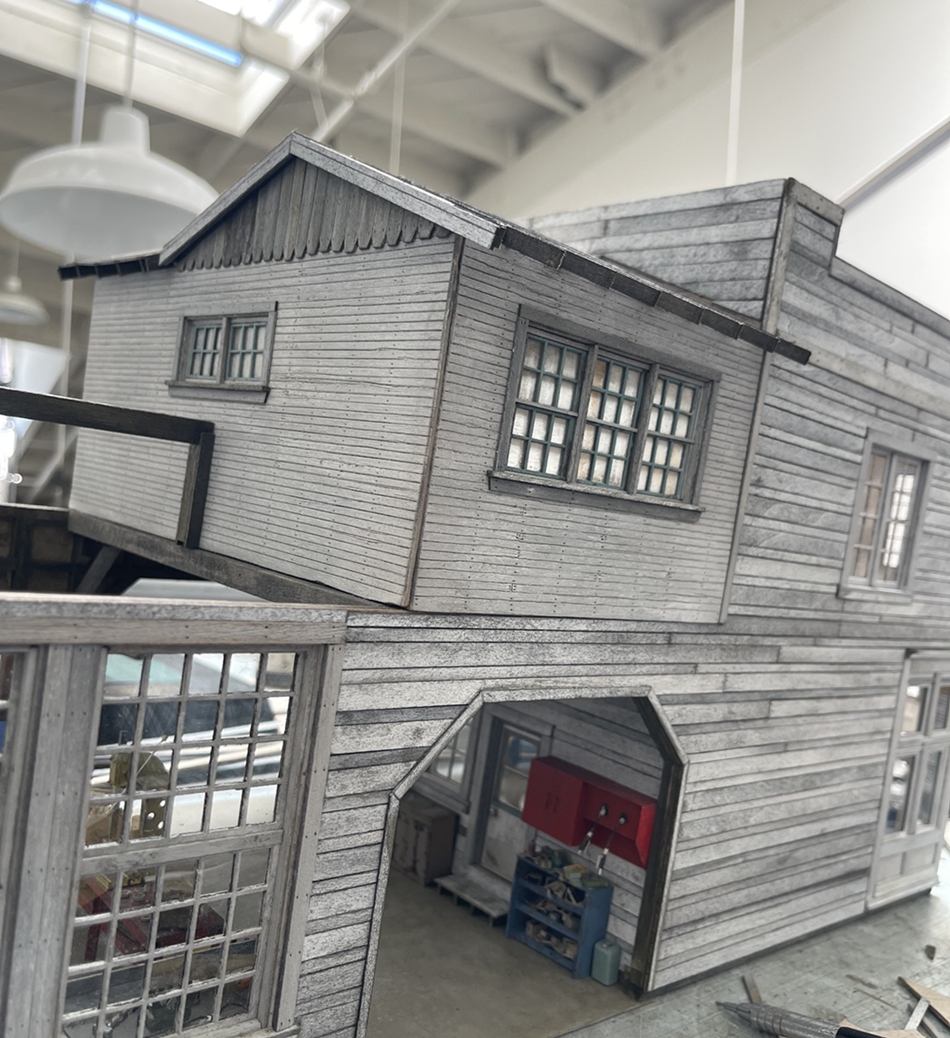


Oh what a treat! I made up these walls some time ago, so for the last couple of weeks I’ve been trying not to lose or destroy them.
With the rest of the building assembled and floor joists and flooring added, they could be attached to the rest of the building. The biggest challenge here came from them being built when the rest of the building was taped together - essentially a big and awkward dryfit that was being added to.
While this worked fine at the time, once the main structure was glued together and squared up, it became apparent that while close, some of the walls were a bit too long, and others a bit too short - great. So, out came the tape, squares, triangles and the knife and glue - and well, things were made to work! ![]()
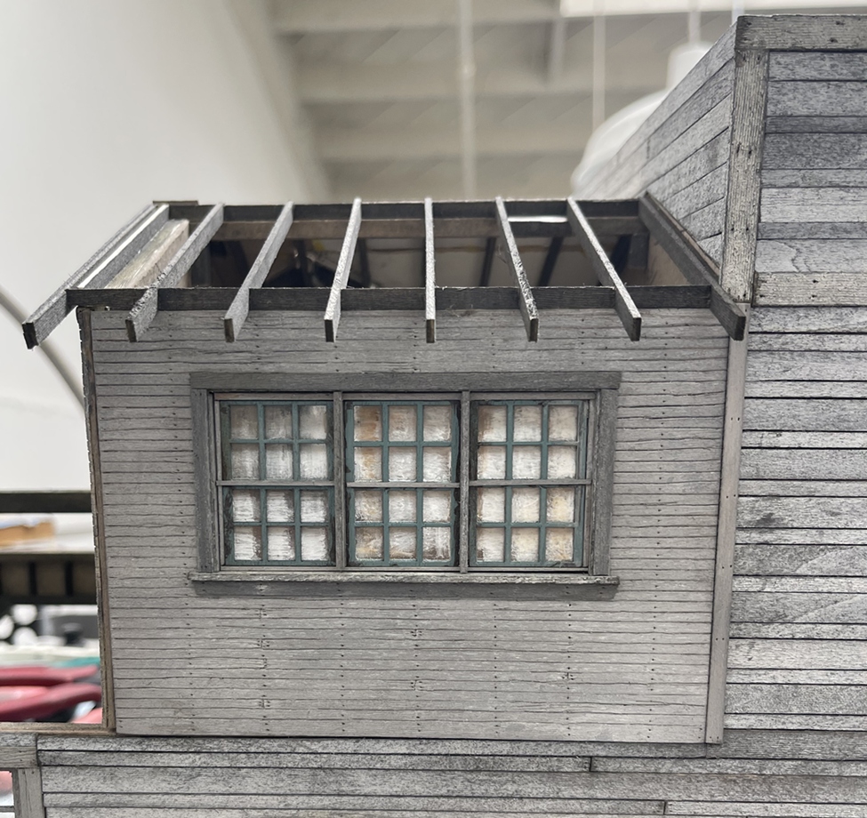
With the walls installed, came the roof framing. Another bit of slow going, as some of the rafters were the same lengths, many were not in order make up valleys where the dormer and main roof met. This took a lot of trial and error, but it worked out. So, outside we went for some photo updates:

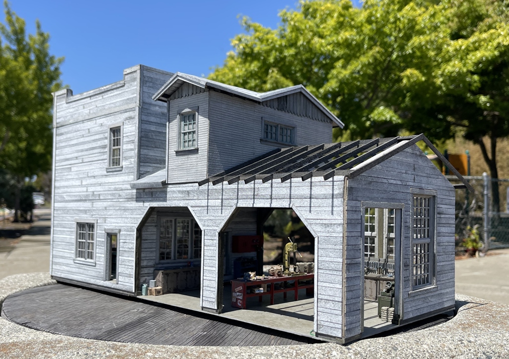


And, what I didn’t mention, this included adding and weathering roofing material, adding some trim, and framing for the rest of the roof over the shop.
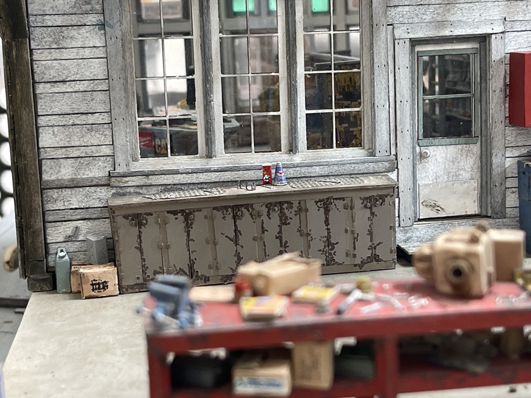
Oh, and as a simple solution, the concrete floor in the shop was remarkably easy to make - a sheet of chipboard (essentially dense, 1/16" thick carboard) sprayed with Tamiya fine grey primer, with several washes of my own concoction of several Vallejo model air colors blended and painted on. I will do this again on other projects. For this application, it was a LOT easier than making up a hydrocal or treated corkboard surface.
And…as I really want to finish this, added and weathered roofing material over the shop and, more trim - first, some backing boards (which naturally hadn’t yet been weathered… ![]() ) so, yes, they were weathered, and while drying, I painted up some roofing material:
) so, yes, they were weathered, and while drying, I painted up some roofing material:

The weathered backing boards above, and as of yet, un weathered, but painted roofing material:

And with some adequate decrepitude:

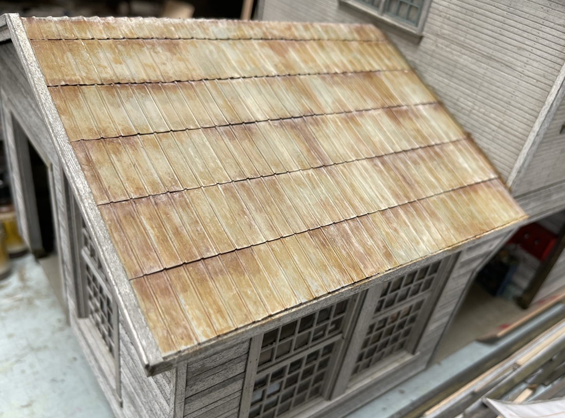

The roofing material is straight out of the model rr junk box. I’m not even sure what scale it is, but, I think it looks right, and with some rustiness, even better!
The building is colored with various ISO alcohol and India ink blends, and the odds and ends painted with Tamiya fine grey primer and direct and diluted Vallejo model air colors - nothing out of the ordinary, which I like as there is no need to start buying more supplies!
OK, there is more to do on this building, but we are getting close to calling it done!
Thanks for having a look -
Cheers
Nick
19 Likes
A heart doesn’t feel strong enough and I can’t just have a ![]() . Keep knocking the ball out of the park.
. Keep knocking the ball out of the park.
2 Likes
This building is just jaw dropping … the problem is, you start off at such a high bench mark Nick … and then each update just blows away the previous one … this building is so amazing that I forgot its part of a bigger plan and not the main focus …
6 Likes
Indeed, I completely forgot this was just a “bit of decoration” for the trucks…
Those pictures of it on the ground look so realistic, could easily be fooled and mistake it for a real building…
1 Like
Thanks for the good words guys - As this moves along…man - still a long way to go.
For whatever reason, I concluded that before finishing the buildings, I’d get into some grading and earthwork, maybe just for some variety - so, a multi step to make up a well used drive aisle:

As there are indeed several steps, I’ve grouped them - the images above are essentially prep work for the following:

And now the tricky parts - applying a variety of acrylic gels. This is a bit of an experiment too. I’ve been using cork mat as a base for a while, and each of these materials, but this is the first time I’ve tried them all on one sheet - we’ll see.
The gesso is essentially a waterproofing agent that serves as a primer of sorts for the following acrylic materials. The pumice gel is similar in consistency to the gesso, but it is blended with various sizes of crushed pumice. I’m using fine everywhere, and coarse in roughed out areas. And finally a top coat of crackle paste. This stuff is pretty interesting as you can sand is down when it dries - - allowing you to knock back ridges and fix areas that need some attention.
This is not a fast process, as each layer needs to set for about a day to dry out - and below, a progress pic:
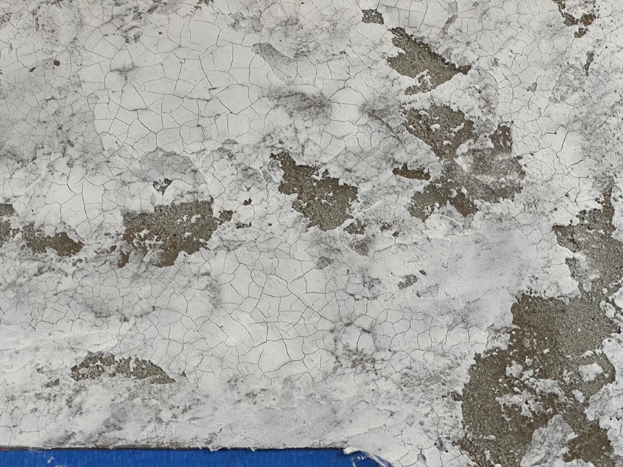
As you can see, my “asphalt” is now good and cracked, with gravel showing where it’s been eaten away over time and use.
I added more crackle paste and am waiting for it to set up. Next will be staining -essentially laying down several washes of Vallejo Model Air.
OK, on we go -
Cheers
Nick
14 Likes
It looks very convincing. I remember using my starter wife’s clay mask to try a similar effect. While it looked pretty good…

2 Likes
I’m adding a truck to this project, a square body, Chevy stepside 4x4. I’ve shown a few pics in the What did you make in your workshop today thread.
But if you want to try this, here is a bit more of an explanation of how you might try it. The base kit is the AK M1008 trop carrier, which is a pretty nice kit as is, and if that’s what you want to do, it seems to build up pretty well.
Starting with some comparisons of the fleetside and stepside bodies:
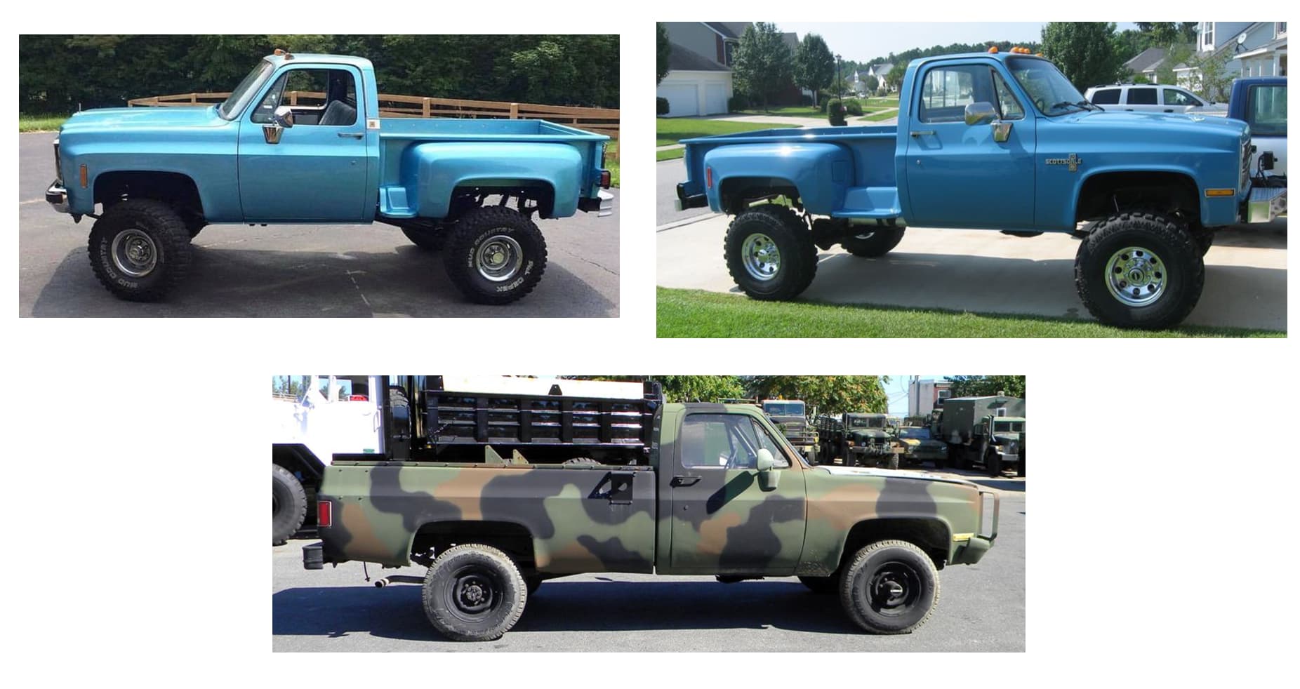
For this project, I’m trying to achieve the short bed stepside, shown in the upper left.
I also prepared a study to get a better grip on what’s going on:

Similar, but obviously different. Starting with the chassis - it needs to be shortened. If you were doing this in real life, you would cut 14" out, just forward of the forward rear leaf spring hanger, which I did, but in retrospect, I’d only cut out 12" - you’ll see why below. You also need to cut 6" off the rear end of the chassis.
For the body, you can keep the rear quarter panels provided in the kit, and cut out the correct sections to use again. This cut out is a bit tricky to locate. The blue boxes show the approximate size of the area to be kept, with the rear matching part of the front fender.
Some things to consider are illustrated below:

As you can see above (the stepside superimposed over the fleetside), both types share a horizontal body line which aligns with the same on the cab. And, the stepside fender tapers inward, so when you cut the part, include enough room to allow for including the taper.
Take your time with this layout and cut, as we are working at a small scale, and errors seem to amplify when eyeballing a build -

Above, you can see the bed deck shortened and narrowed as needed - this took a couple of tries to get right - under cutting, you know - better than over cutting - or, well just don’t cut it too short! ![]()
The donor fenders are cut wide enough for you to scribe some lines on the inside, so that you can bend them inward to match the taper on the real thing.
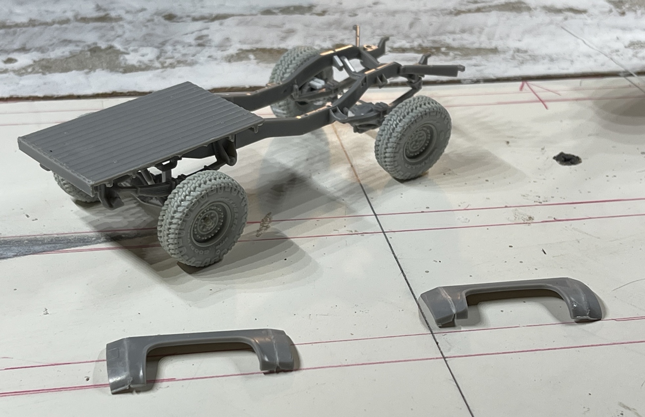
As I am using big tires and like lifted trucsk, well this got a lift kit too. 5" blocks on the rear leaf springs, which is easy enough, but remember to file them on the front facing direction, so that you can clock the rear driveline to the transfer case - if you don’t do this, the rear diff will not be oriented toward the transfer case and the driveline will not sit flush to either.
The front lift is a bit trickier - you could just add blocks there too - but, in real life that is a hard no go - steering the truck will cause sheering, and the blocks tend to shift. In real life, you’d but new leaf springs with the desired arch. For this, you could make new leaf packs, but I was not in the mood to fuss with that - a pretty tedious process, so instead opted for the lazy approach - to rearch the leaf packs from the kit of course! ![]() translated: bend them so they don’t sag, and instead have a positive arch, that looks about the same on each side. Once you’ve done this you wild find the hangers no longer align with the locations in the kit. To resolve this, cut the hangers off of the leaf packs, install them in the kit provided locations, and then drop the rearched springs in place.
translated: bend them so they don’t sag, and instead have a positive arch, that looks about the same on each side. Once you’ve done this you wild find the hangers no longer align with the locations in the kit. To resolve this, cut the hangers off of the leaf packs, install them in the kit provided locations, and then drop the rearched springs in place.
And…another point - the kit offer posable, but fixed steering - that is you can build it with the wheels pointed forward, left ort right, but can’t keep it adjustable, because there is a fixed point, steering stabilizer on the drag link. Well, I want to keep the steering adjustable. To do this, you can make some little retainers, to go inside of the upper and lower ball joints, as shown below:

Oh what a treat - and easy to do… ![]() This is not hard to do, but you need to be really careful when gluing. What you can’t see here is that the kit steering knuckle slides in to place, and as it is not intended to move when built, well, the part stays open. This is not good it you want to turn your wheels left or right.
This is not hard to do, but you need to be really careful when gluing. What you can’t see here is that the kit steering knuckle slides in to place, and as it is not intended to move when built, well, the part stays open. This is not good it you want to turn your wheels left or right.
What you see is a small piece of material, maybe .030" x .060" mounted to keep the kit provided ball joint in place - but, if you just glue these (x4) in place, there is a good chance you’ll inadvertently glue the wheel in place. To get around this, I added two sheets of .015" x .040" strips to each retainer before installing, making the whole part into a little bracket that could be slipped over the steering - but avoiding getting glue where it shouldn’t be.
The drag link is the kit part, with the steering stablizer removed, wire added to the end/heim joints, and widened just a bit - I mean about 1/16"! you can see the tiny piece of alu tubing - this eliminated the bit of toe in it was suffering.
While I blasted through this explanation, take your time while doing it - and don’t freak out if things break, fix them as you go and remember what you might have messed up so that the problem doesn’t ripple through whatever you’re trying to make - guess why I offer this tidbit???
OK, back to the steps:


Making the bed is on one hand not that hard, and on the other, as noted above, not something to race through. For example the bed height should be pretty close to the door window sill height - why do I know that?? because once I got mine built I realized it looked a bit off - hmmm, that’s weird - oh - shoot - it’s about 2mm too tall - crap. So, time to cut up the firmly glued and assembled parts - what a treat! ![]() The rest is more slow going with various pieces of styrene.
The rest is more slow going with various pieces of styrene.
Making the fenders took several steps - first, cutting, shaping and firmly gluing the kit piece, that is starting with the basic shape, then back cutting it to allow the front and rear facing panels to be tapered. When you’re done with this, you’ll see the part is now generally “U” shaped, meaning it won’t lay flush. To resolve this, gently sand the heck out of it on a sanding block until it will lay flush. Once it’s flush, you’ll see there are obvious gaps between the outer most edges and the surface you are laying it flush on. I filled these with .040" styrene, and yes, when done, resanded it flush.
Next step is to make an inner shelf - trace the entire fender onto a sheet of .040" styrene, and cut it out. This shelf will serve two purposes: the bed attachment surface on the inside, and the attachment surface for attaching the fender, or in English, the place that you will glue a piece of .030" x .250" strip of styrene.
So imagine a fender sandwich, with the kit part on the outside, your new .040" shelf on the inside, and the .030" x .250" styrene glued on its narrow edge between both “outside” pieces - Sorry too confusing - here’s a picture:

Yes - on the outside the kit part tapered, filled and sanded - then, a piece of .030" x .250" strip - then, mounted to the bed, the .040" inner shelf. Again - obviously it’s possible, but take your time and steer clear of coffee for a while ![]() Oh - you can also see the piece of fill material in the kit part - if not, you’ll have a very big gap.
Oh - you can also see the piece of fill material in the kit part - if not, you’ll have a very big gap.
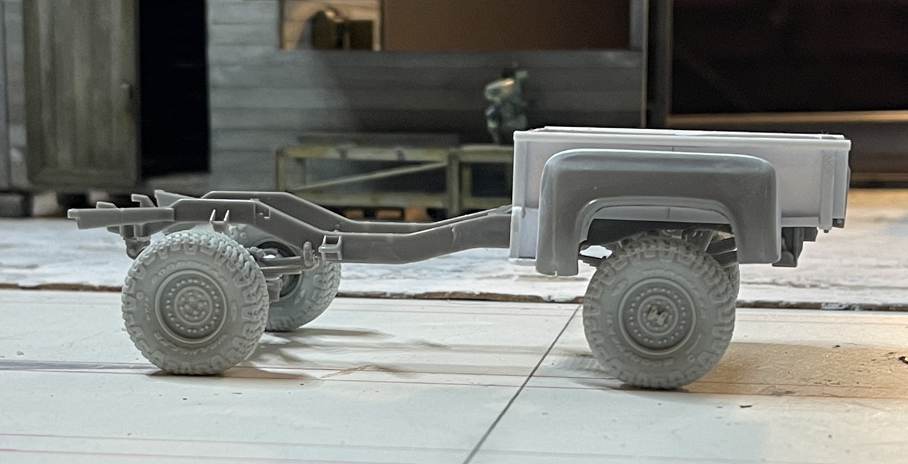
Here’s where it sits right now:

In this picture you can see why I suggest cutting 12" instead of 14" out of the frame, as the “step” (between the cab and bed) is a bit narrow - not bad, but enough to see if you know what to look for. I think this happened because I cut the frame rails with my trusty Atlas razor saw - that I cut everything with - metal, wood, and…kits! as such - the blade is thick and a bit chunky, and I think I cut too close to the line so we have this.
The cab is at an angle because it’s balancing on the chassis and not mounted - it will be level or close to it when we’re done -
OK, thanks for having a look -
Cheers
Nick
12 Likes
Awesome looking so far. ![]()
2 Likes
Nice job on the stepside.
1 Like
This is why you are the truck king. As there were several diffderent type of engines used in these, my guess is that the engine from the Hobby Boss Land Rover kits (of which I have many as I didn’t use a lot of them) may fit convincingly, if you want to show it off. Less some of the more intricate plumbing, they look pretty standard. Let me know if you want me to send you one,
2 Likes
What a cracking job on the scratch truck … brilliant.
2 Likes
Hello gents, and thanks very much - I’ll be the first to admit I have a problem ![]() and have wanted a Chevy square body model of any kind in 1/35 for a long time - this is just too good to pass up on!
and have wanted a Chevy square body model of any kind in 1/35 for a long time - this is just too good to pass up on!
@18bravo, hi Rob, thanks for the engine offer, but not needed for this, as I’ve already faked in an oil pan, flywheel and transmission. But, I will certainly keep your offer in mind because as you likely guessed, I didn’t buy just one of the AK kits!
Before I started work on the Chevy, I was pretty immersed in the buildings, which no doubt inspired the need to get after the truck - I was going nuts - and why? Because I was sick of detailing the buildings, and now a few days later, can look back and be pretty pleased:

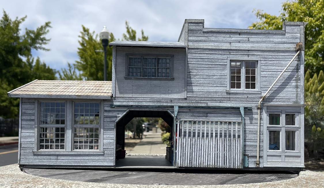
The right side got a period-looking sliding gate, and downspouts, while the left side got:

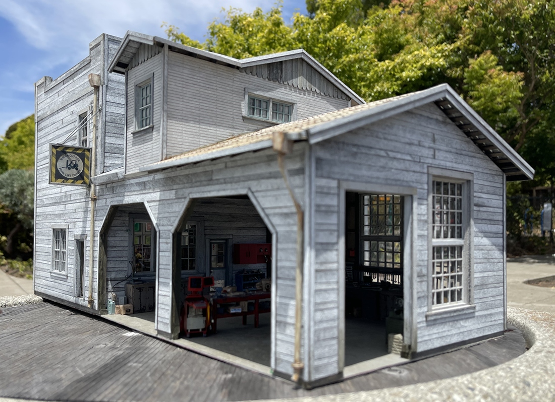
downspouts and a sign:
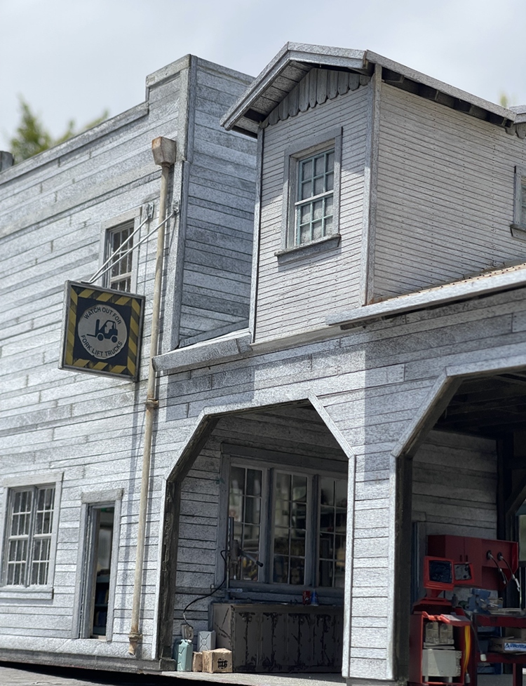
While tough to read here, the sign is a warning for forklifts crossing! The real version is in my nhood, and a couple years ago I took a picture - lol- so, here it is in use
And, spent some time on the small shed:


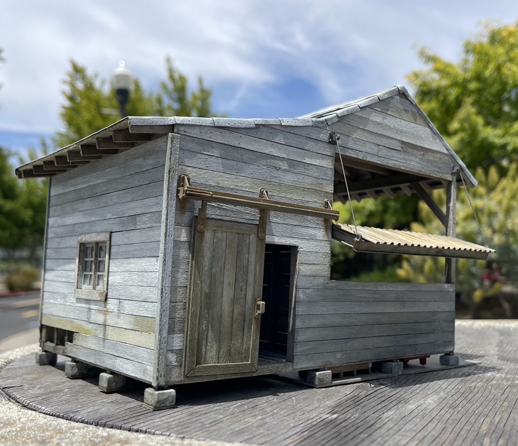

In addition to the tools and a sign, well, shoot - that eave - it’s now version 3! ![]()
For such a simple detail, well - it took a few tries to get right. While in the middle of adding the shop tools, I realized it still didn’t look right - crap. So, out came the knife and razor saw, and the eave, again. Right or not, this is how it will stay -
OK, thanks for having a look -
Cheers
Nick
12 Likes
Nice touch with that Auto-Lite sign not hanging straight
![]()
![]()
1 Like
Ha! glad you noticed! good eye! ![]()
Cheers
Nick
1 Like
Although its been mentioned by Robin, that lop sided sign is very clever …
3 Likes
Yes, some things are very clever, …
… despite being mentioned by me
![]()
![]()
2 Likes
What a Masterclass. And the devil, or rather the angel is in the detail. The shed – check out the variations in plank colours/tones, are any two the same adjacent to each other? And the rot in the footing of the wall below the Spicer sign. And the precision of the nails on the Auto-Lite wall. Perfection. If I had the barefaced temerity to suggest any improvement, perhaps the main building needs a tad more weathering/rain-stains like the shed has. But I don’t, so forget it.
(Btw what are the buildings resting on, is that a turntable for photographic or airbrushing purposes?)
3 Likes
(I know I’m late to this show but…)
![]() Great idea on that cabinet bench. Thank you.
Great idea on that cabinet bench. Thank you.
2 Likes
Brilliant is all I can say.
1 Like