Looks to me that the hydraulic rams at the corners act upon the rocking beams which are fixed at their inboards ends via links to the body .
It appears the center of the rocker acts upon the shaft that goes through the machine and is fixed to the wheels , thus raising and lowering the body of the vehicle along the shaft . This is a second class lever - remember simple machines in your science class ? The arms that carry the lumber are fixed to the body of the vehicle and rise and fall with the body as it travels about the vertical shafts .
I remember these straddle lifts in the local lumber yards as a boy .
2 Likes
Edit - I think you are correct in that the rams at the corners are for ride height and it appears that the arms that carry the lumber can be raised or lowered also via what appears to be shaft driven winches.
I think there may be a problem with the model in that arrangement of the vertical shafts at what may be considered the rear of the lift as the shafts intersect the axles of the differential.
Beautiful work Nick - always a pleasure to watch what you do.
Cheers- Richard
1 Like
Me thinks that the lift arms need to be able to move laterally to be able to grab loads of varying widths. If they are fixed all the loads must be the same width AND the loader will have to slide the lifting angles in under the load while driving over the load.
Compare with the arms on this website:
My interpretation of this image which I found here
2 Likes
Yes the load pick up arms swing out as they are lowered and then back in as they are raised. The memory is fading but I ran one of these for a couple of years 50 years ago. The arms operate independently of the carriage height.
2 Likes
Other interesting image showing uncovered chain drives to rear wheels and chains to hoist the load
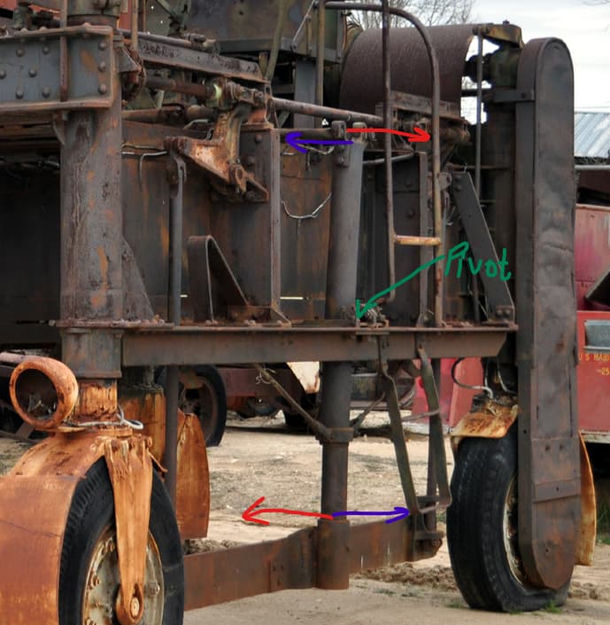
Thanks to @Buckeye Tim I think I might have figured it out.

- Roller that rides up/down on nr 3
- Lifting arms moved up/down by chains (4)
- Fixed rod
- Chains on axle turned by gear unit (5)
- Worm gear???
- Lifter (or whatever it is called)
If nr 3 is vertical the upper angle, at the roller, of the lifter will not move sideways.
When the lifter is pulled up by the angled arm, nr 2, the lower edge of the lifter will swing inwards and clamp the load. There is not a whole lot of lateral movement so the loads will not to have a fairly standardised width …
The original (large!) photo is here
Another large photo, more modern I think
2 Likes
Hello gents,
Seems this weird old rig has become the catalyst for some discussion!
@RDT1953, Hi Richard, and thanks. You know, I wondered about the point you raised, about the vertical component/leg going through what looks a lot like a differential, or at least CV or ball joint - but, zooming in on my example vehicle:
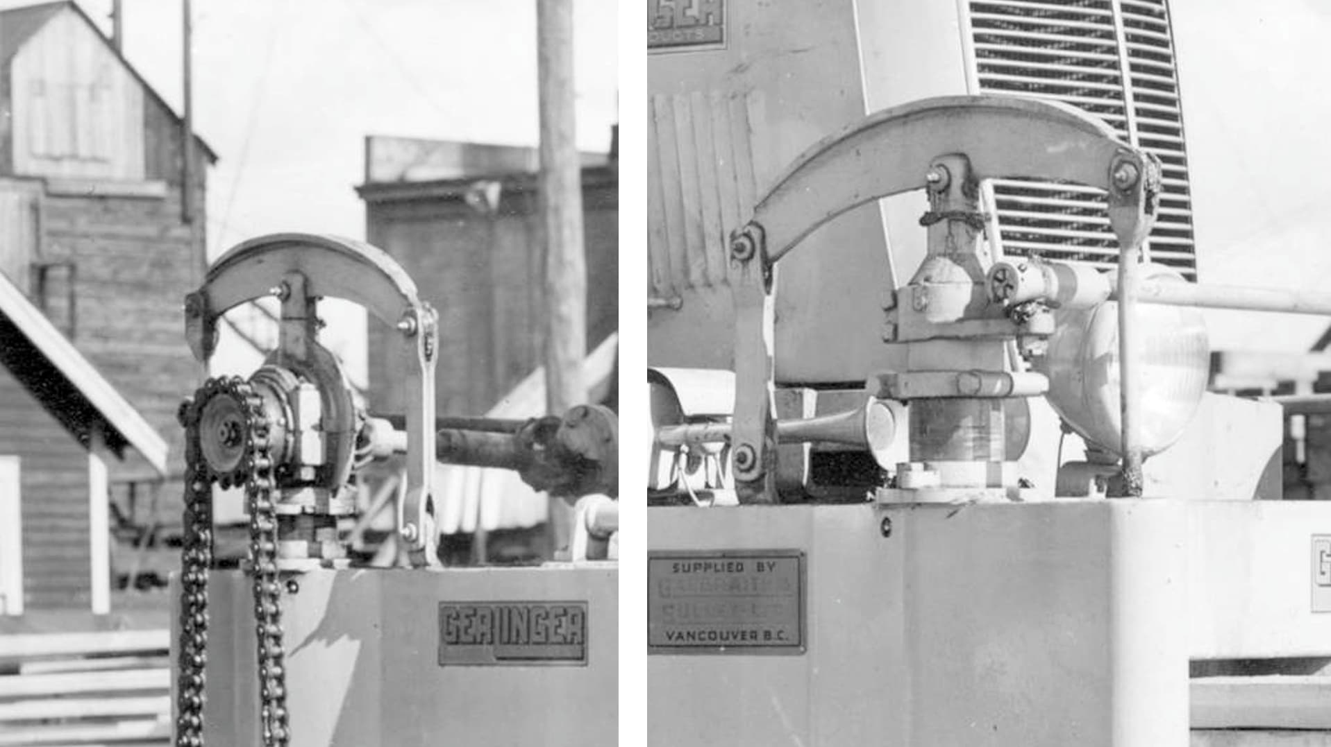
Which I should have done before…well, you can see on the left, how this works. It certainly appears that the leg goes up and down as suggested, but - what a surprise, it sure looks like there are propeller shafts coming out of the rear diff, with U-joints! suggesting the entire unit goes up and down! wow - almost wish I had worried more about that before ![]() could have given me the chance to build an independent rear end like on a Corvette or GT40!
could have given me the chance to build an independent rear end like on a Corvette or GT40! ![]()
@Uncle-Heavy Hi Robin, so much to ponder here - I’ll start with something easy; the chain drive seems to be a very common feature on these machines, which makes sense as it is a relatively simple idea to implement.
As to the workings of the cradle - I get your notes, that is, I understand what you are suggesting, but still don’t know exactly how all of the parts work together. When I started this, I looked at many images, mainly early versions (as they were available), that were clearly mechanical. The up and down feature of the cradle was relatively evident and easy enough to grasp:
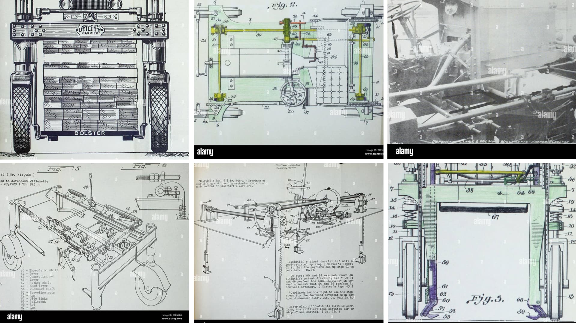
If these old images were bigger you could figure out that the cradle was raised mechanically. It is not as easy to discern though how if would clamp/squeeze? Notice the image in the upper left, which shows an elevated bolster beneath the material - allowing the cradle to slide under. But, you can also see in the lower right, clamps that look like they could project under a load - as to how thy work, or if they do that? no idea ![]()
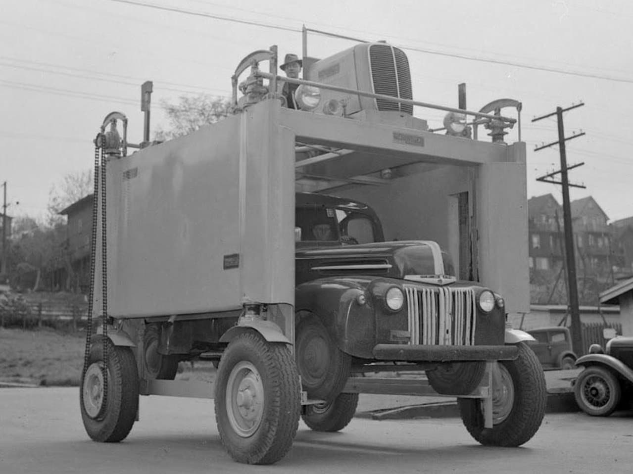
As I mentioned above, the unit below is the basic prototype I’m basing this build on - knowledge gaps and all:

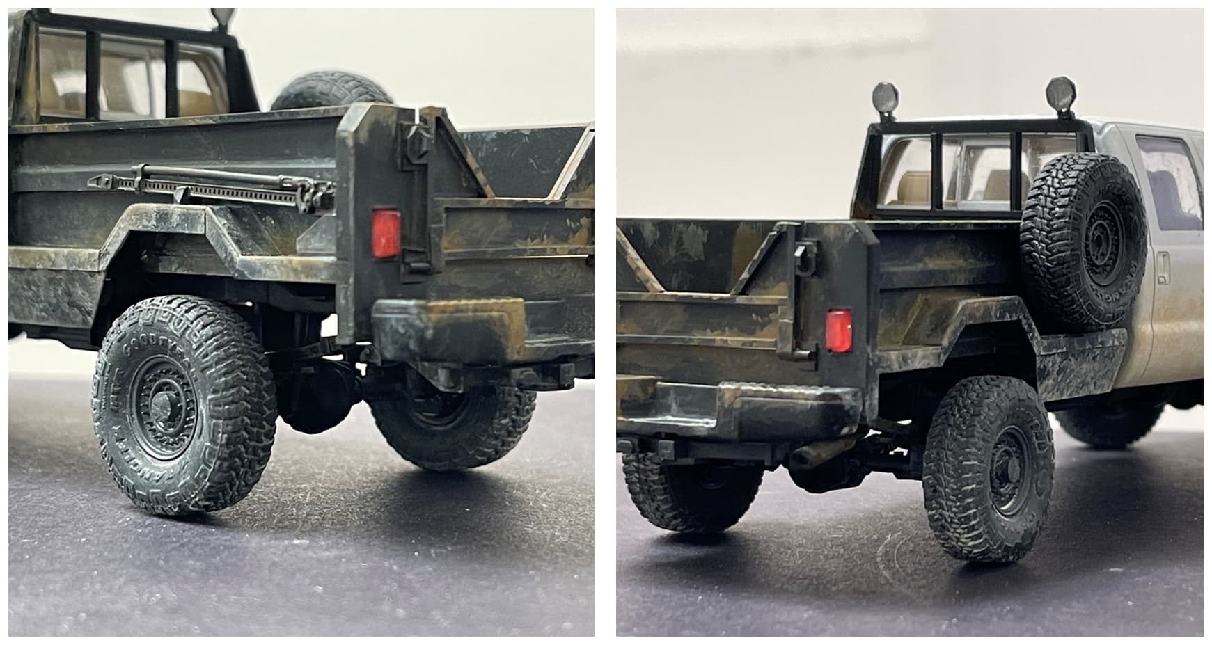
From this image, I have no idea how the cradle would squeeze?, though it seems reasonable enough that it would. However, on the version below, which seems to be of the same era,
you can see some notches in the sidewall (to the driver’s side of the pickup) which might allow arms to swing inward? how they swing in??? I don’t know! ![]() if the they swing in? I don’t know!
if the they swing in? I don’t know! ![]()
![]()
And for now, that’s just fine. I might keep searching for images. While I have several images of these saved, they are only moderately helpful in addressing the questions we are discussing. I have had luck on other projects searching machinery/equipment auction sites for walk around photos, but these seem to be too old for that!
I’m still working on the chain drive - hoping a long shot idea works!
Cheers
Nick
5 Likes
The arms do swing in and out at an angle. The loads and blocks are a standard width to fit on a flat car or semi flatbed trailer so the swing/articulation of the arms is not that great. What you are seeing on clamps is simply a long piece of angle iron running from the front to the rear lift arm.
Very old units at one time might have had individual clamps but that is just to complex a machine for the operating environment which believe me is pretty rough and ready.
2 Likes
I got the impression that there were a few different solutions.
Some seem to have used chains to attach to the load or a pallet under the load.
What I think I am suggesting is that your machine should have some kind of in-house solution to the problem theat looks like it could work.
Pivoted lift arms like in the image of the rusty one, just needs something to push/pull on the upper ends or the sliding angles of the yellow machine seen in Australia.
The load is carried by the angled iron at the bottom so the lift does not depend on the clamping force (friction), just needs to move the angled iron in/out by maybe 5 inches each side or the width of the horisontal lip of that angle iron.
2 Likes
Great research in seeing how this rig works … very cool wagon and also very intricate as well
2 Likes
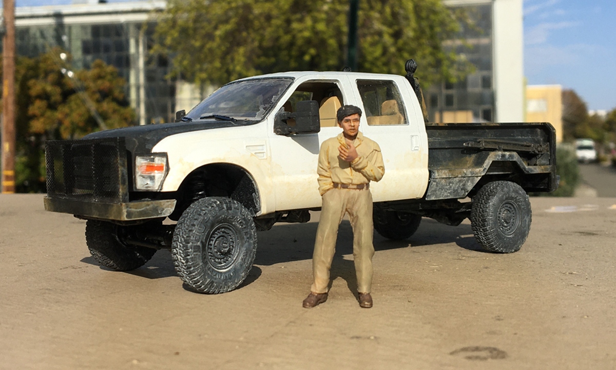
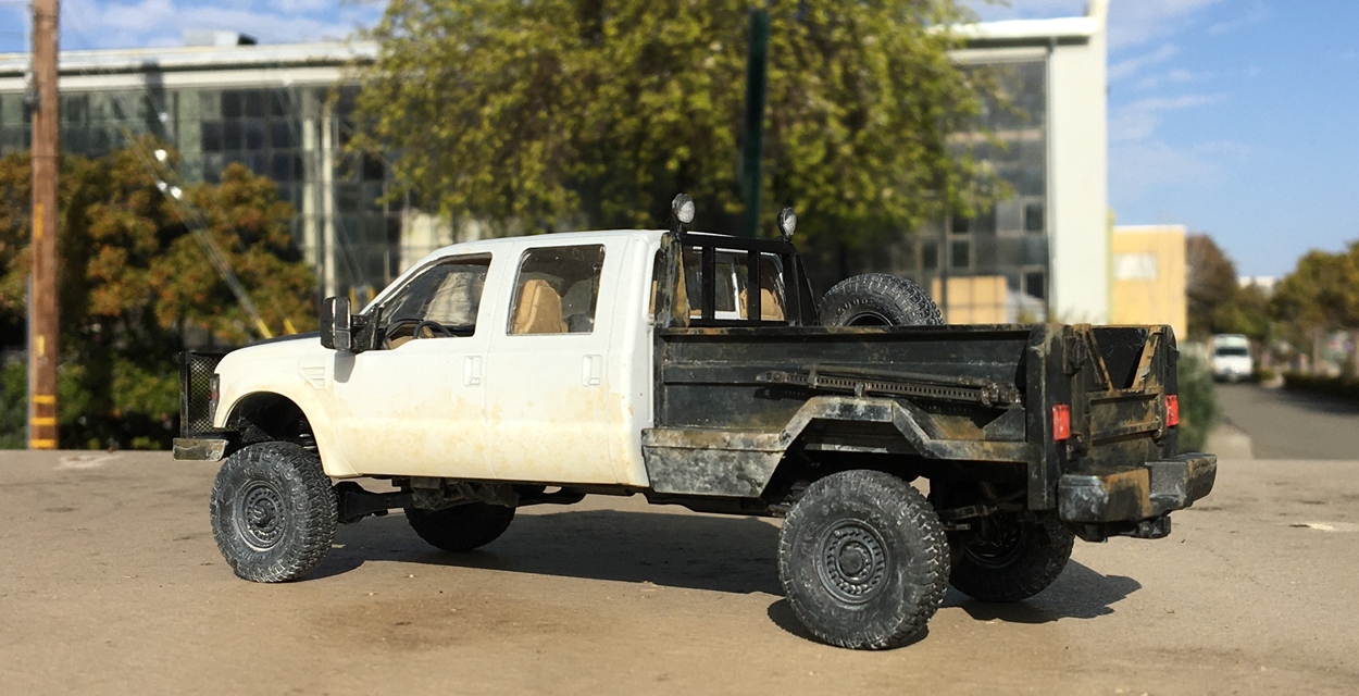
Ok guys, back with some progress. I’ve only been on and off on this over the last couple of weeks but today can show an update. Some paint arrived a while back, and I began painting the three builds that were done. Starting with the pickup:


I really like how this turned out - and the lumber truck and lift:
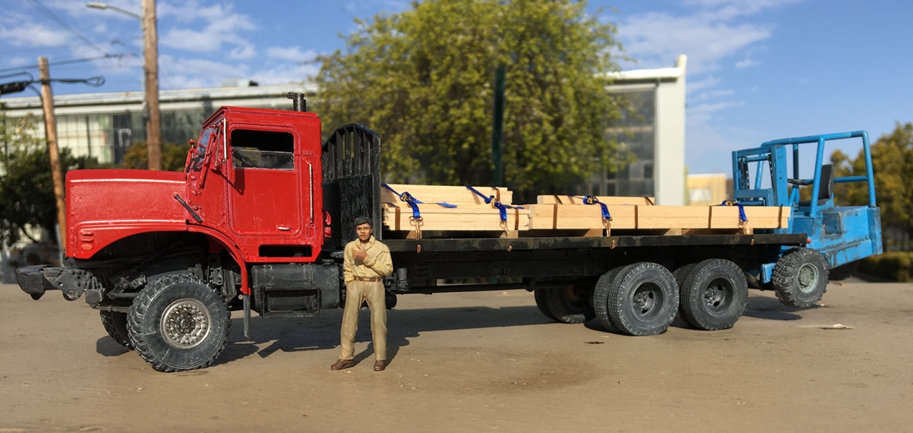


And both:

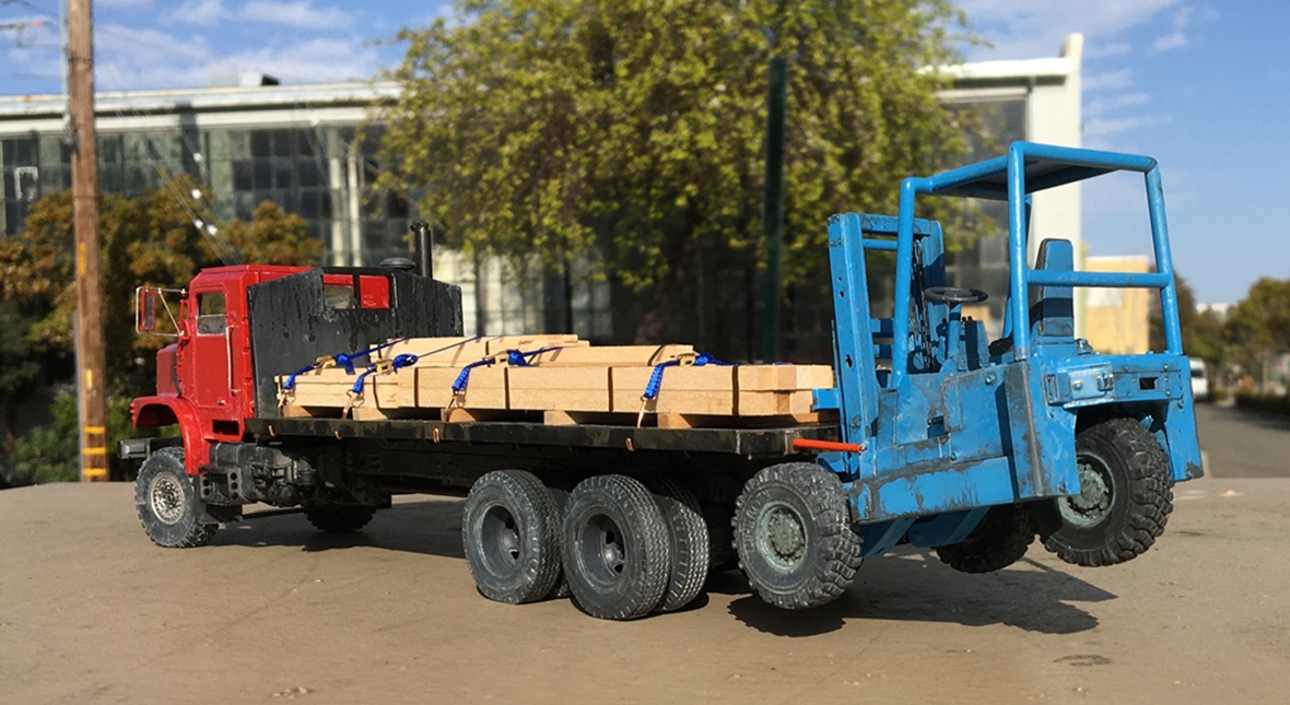
So far so good. And on to more builds starting with the straddle carrier:
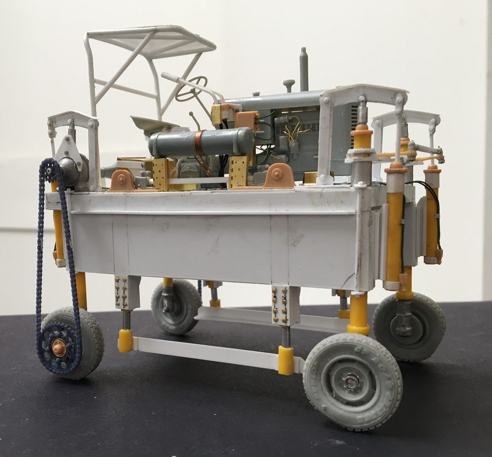
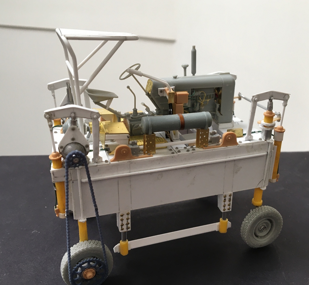
This might be ready for paint too - the chain drives are 3d printed, intended for use on a 1/12 scale motorcycle, so perfect for this! As they were not actually intended for this, I made up some adapters to attach them, and figured out to to cut out chain links and reassemble without looking awful. This was a lot slow going, but not exactly bad - just required some patience.
On the other hand, this, well, I thought about that post where it was asked if you had ever “binned a kit” ![]() uhh, no, not yet, but this has not been a cake walk:
uhh, no, not yet, but this has not been a cake walk:
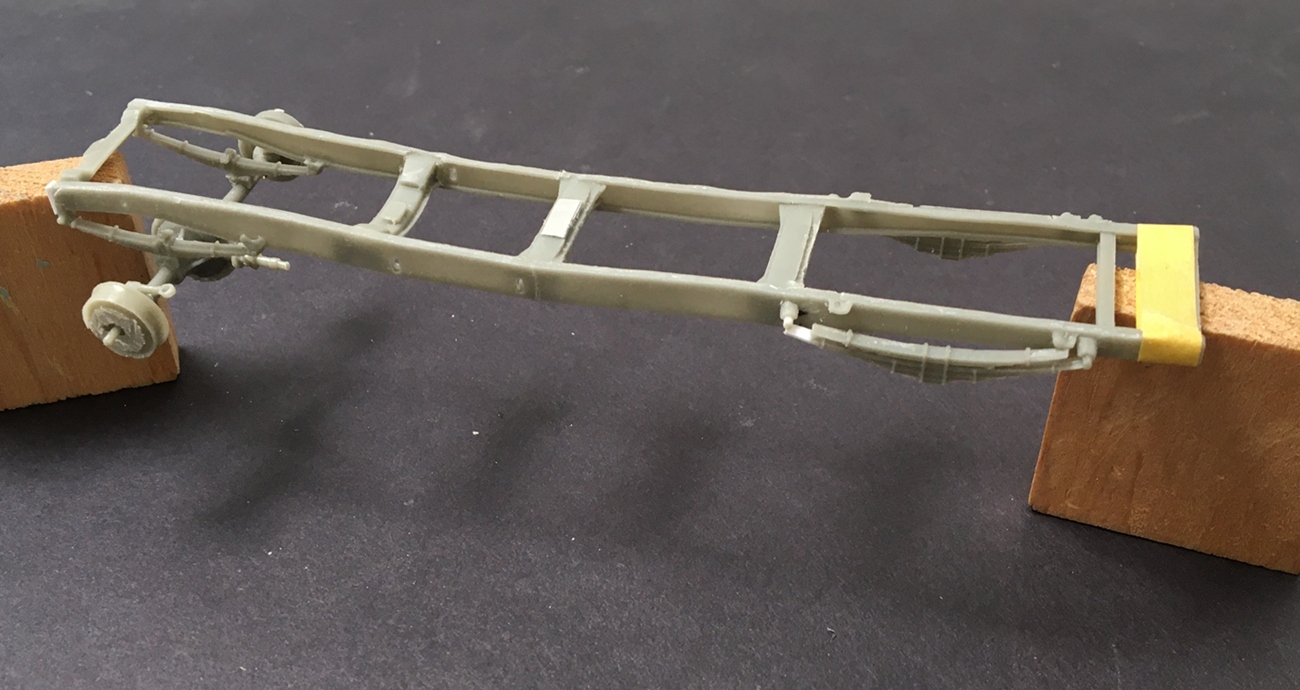
“how hard can it be to make up a frame and add an axle?” Try it yourself and find out ![]()
This is the Dnepro 1941 Ford Marmon Harrington 4x4 - yes, an obscure subject that I really like! So the kit, I’m assuming, is small production etc. On one hand, I’m really glad they made this, and as an enthusiast of all things 4x4/6x6, come on! who could ask for more?!?! ![]()
Some parts are really nice and finely molded (it’s a resin kit), others less so - the instructions are light. So my unsolicited observation so far is that if you’ve built and enjoy building finely detailed/small part kits (think MiniArt with small parts, though not as many) and the challenge of cottage industry resin parts, this kit is for you. If not, you might think twice before jumping into it.
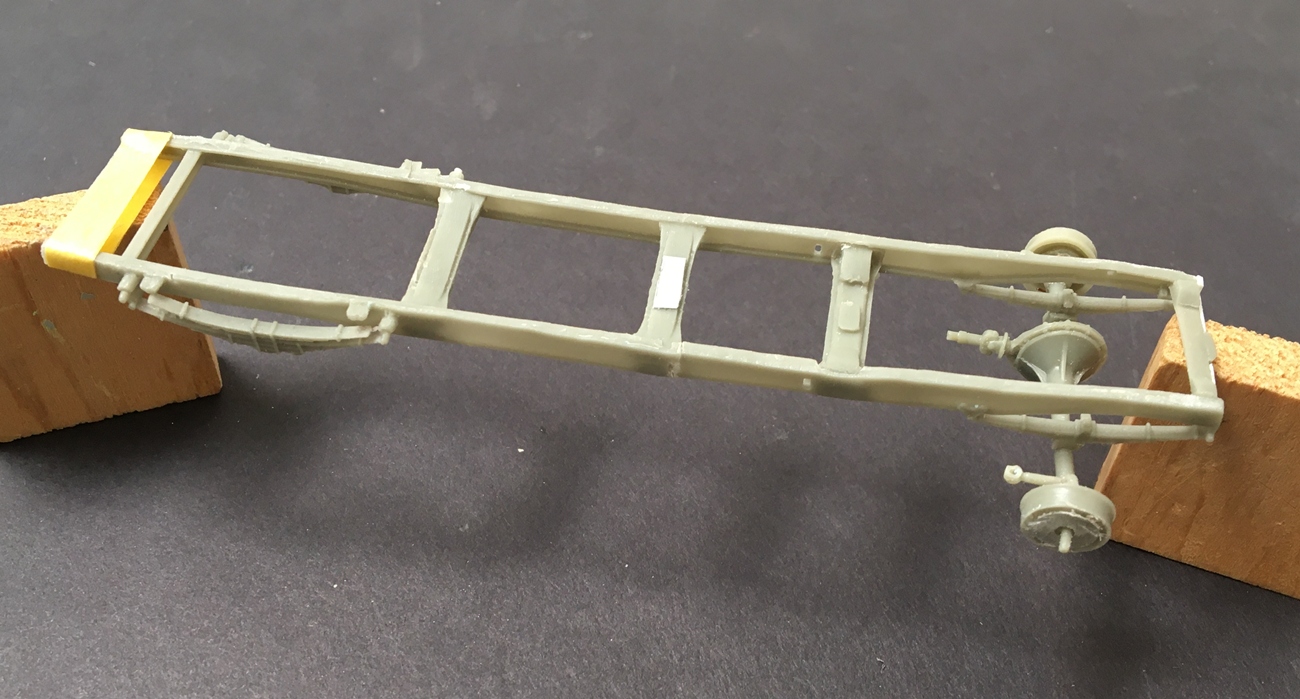
Despite a few challenges along the way, like when I snapped a frame rail in two ![]() I concluded that I needed posable steering so now I have it. I could not figure out what exactly the instructions were intending, so decided to not worry about that, and adapted the kit parts as I saw fit. In general terms, this involved filing, drilling and wire pinning parts together. Not a complete disaster, but it was a challenge. The kit includes a nice little V8 engine, even has individual spark plugs - but, also has vague instructions and a few other parts less great -
I concluded that I needed posable steering so now I have it. I could not figure out what exactly the instructions were intending, so decided to not worry about that, and adapted the kit parts as I saw fit. In general terms, this involved filing, drilling and wire pinning parts together. Not a complete disaster, but it was a challenge. The kit includes a nice little V8 engine, even has individual spark plugs - but, also has vague instructions and a few other parts less great -
On we go - thanks for having a look -
Cheers
Nick
14 Likes
Great update Nick and the colour choices you opted for cannot be faulted. They look just right, nice contrasts and exactly what I’d expect in these type of yards.
2 Likes
OK here’s the deal Nick – I’ll just mail you a Thesaurus with all the best complimentary words highlighted, that should cover all your miniatures creations…although barely sufficient for the straddle-carrier – expletive-expletive-are you-expletive-kidding?? Loving the chain-drives too, genius.
Anyhow it’ll make room instead to annoy the hell out of you with petty snipes…in the interests of constructive crit, natch ![]() (1) the guy seems to have some flash between his legs…yeah I’ve waited years to be able to type that (2) The tyres…did the pickup drive over freshly painted road markings or snow? Any chance you could just (even ultra-lightly) dust all the vehicle tyres with a khaki-ish tone? It’s just that to my eyes they jar with the ground they’re on right now.
(1) the guy seems to have some flash between his legs…yeah I’ve waited years to be able to type that (2) The tyres…did the pickup drive over freshly painted road markings or snow? Any chance you could just (even ultra-lightly) dust all the vehicle tyres with a khaki-ish tone? It’s just that to my eyes they jar with the ground they’re on right now.
3 Likes
Wow! I first thought it was a real picture from a lumber yard! Sensational as is all your work.
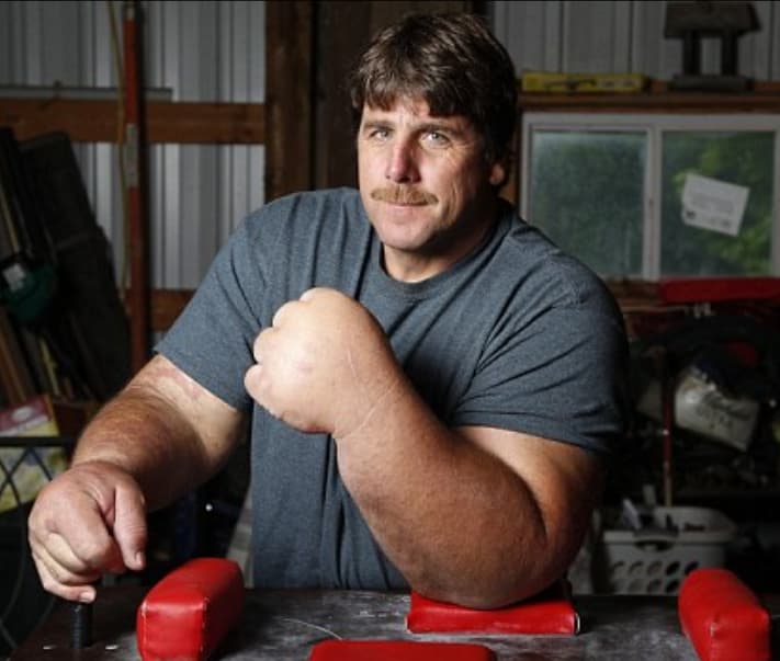
Is it just how the picture was taken or is buddies hand the size of the Hulk’s?
1 Like
Oh yeah! Lovin’ the straddle carrier!!! Man putting that thing in high gear and runnin’ around the yard was an adventure in and of its self especially if you were moving w/out a load on. Young and foolish in those days. Now just old and foolish!!
2 Likes

@Buckeye, wow! you’re the first person I’ve met who both knows what a cradle carrier is, and has driven one! From what I can tell, it’s a steerable crate, lifted high off the ground with no suspension! ideal for driving fast!

Many are challenged every day with - “big hand and poorly tailored trouser syndrome” - and yet they march on…who are we to mock???..This poor guy probably didn’t think when he woke up and got dressed that he’d be subject to…this… ![]()
![]()
Leading us to another tough situation @Dioramartin, Tim… misdiagnosing soil characteristics left on tires/tyres (another murky situation btw)…:
well - tire treads…dirt on some look light and others dark, just depends on what you drove or are driving through - and the Ford truck:
Well, the color of the wash is Life Color Light Dust, one of my favorites that I use on most projects. This truck will eventually be placed on a diorama base made up of, yes, light colored soil and crushed rock, not asphalt, or, the dark color in the image up the page. In fairness, that shot was taken low and with direct sunlight on the tire - but, as you can see above, it’s less glaring than it seemed.
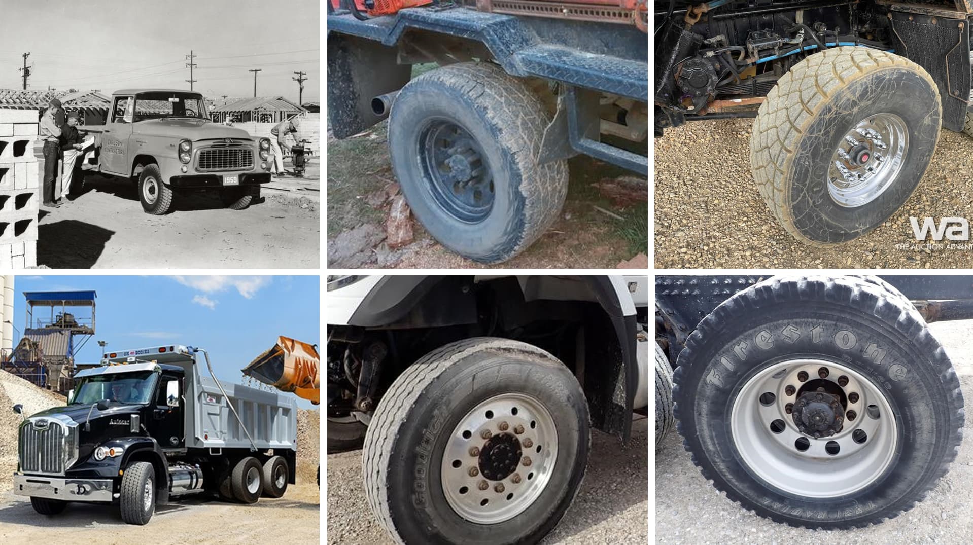
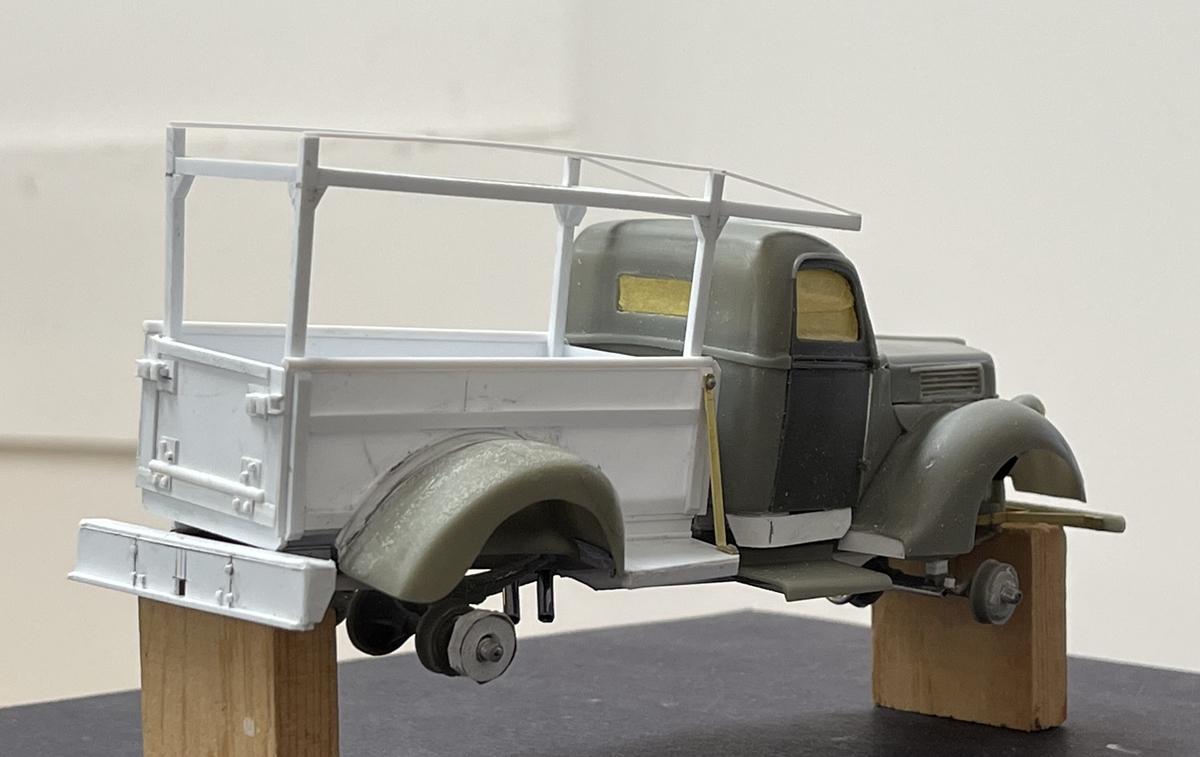
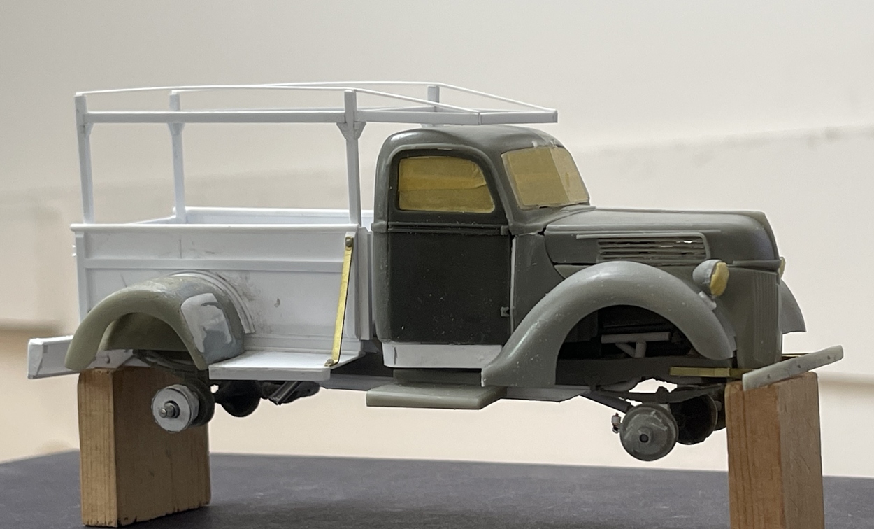
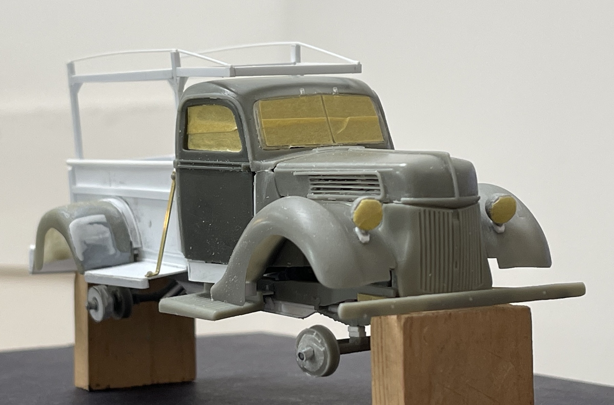
OK, on to an update on the Ford Marmon Harrington - well, this has not been a great build. My initial idea was to make a truck that looked like it was restored - shiny and beautiful, but now that I’m building it, nope…it will look like a clapped out, sagging yard truck. As you can see below, this vintage truck is pretty cool:

The 4x4 dually of old is pretty neat, and I really wanted to make something nice, like in the lower left of lower right. That’s not going to happen. Instead, it will be like the image in the lower center! a bit less flashy - and why you ask? this is why:


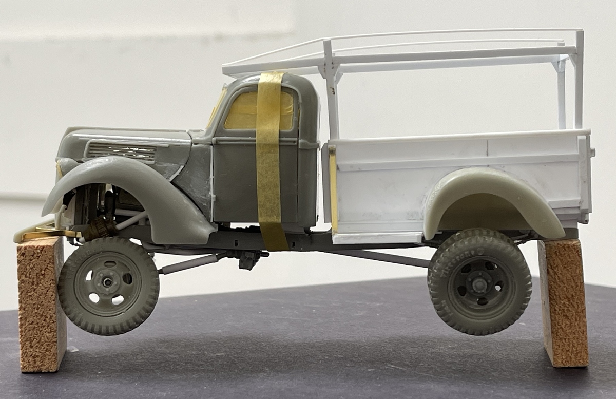
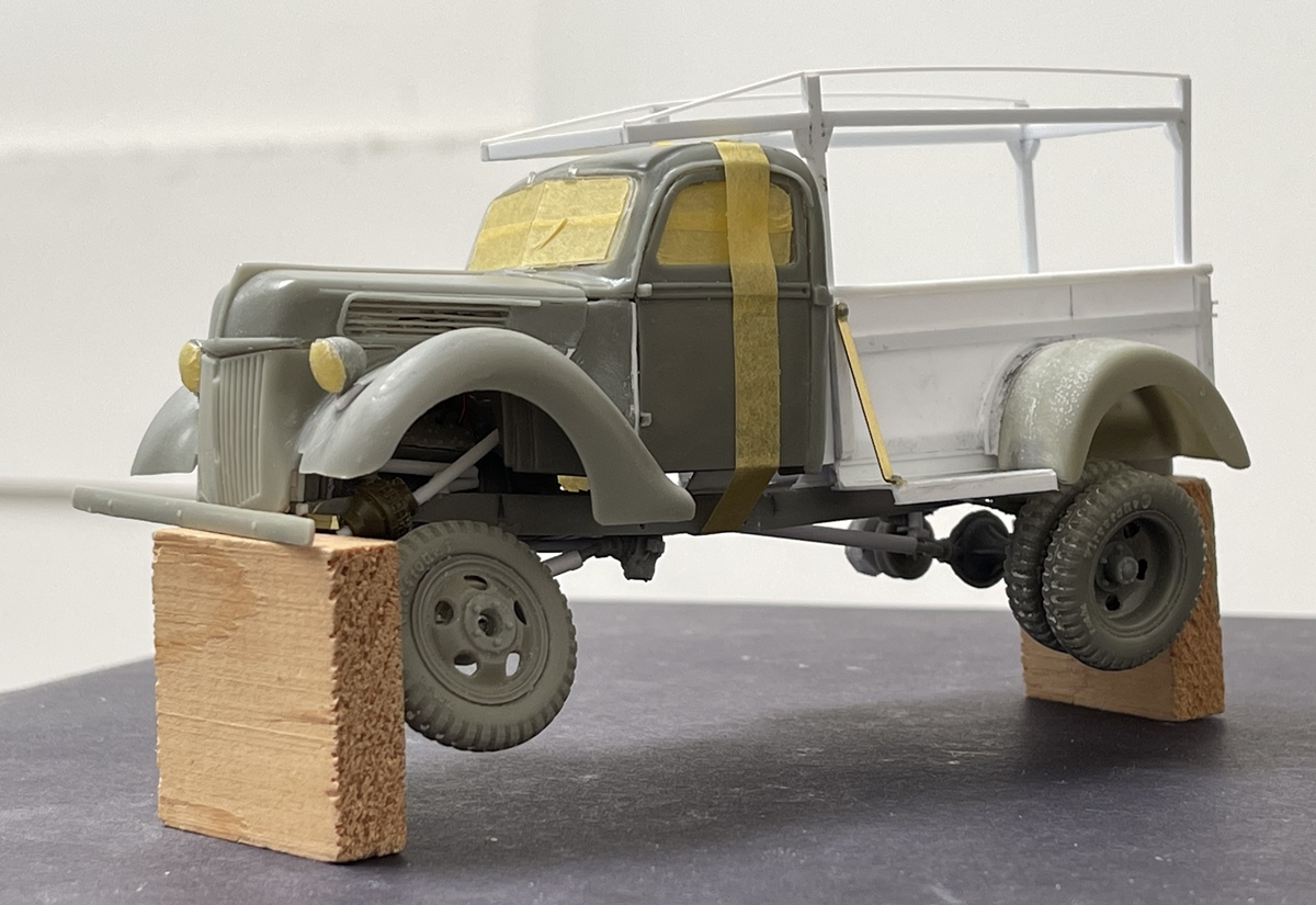
How much beauty??? All of it! It’s on blocks because while dryfit, the tires (obviously) won’t easily stay on the hubs! ![]() But they will fit fine with some glue. And the model, it has not been easy to assemble and the fit is lacking (body parts not aligning, gaps etc) - which would be a real bummer if I really wanted to build this up as a showroom beauty, but for what I’m doing, I can live with this. The bed worked out as well as hoped - fitting the oversized rear fenders was a challenge, but they turned out ok
But they will fit fine with some glue. And the model, it has not been easy to assemble and the fit is lacking (body parts not aligning, gaps etc) - which would be a real bummer if I really wanted to build this up as a showroom beauty, but for what I’m doing, I can live with this. The bed worked out as well as hoped - fitting the oversized rear fenders was a challenge, but they turned out ok
On we go -
Cheers
Nick
7 Likes
Nick, if all this static plastic realm was some sort of Kung Fu, you’d be one of the Black Belts up in this Dojo ![]()
2 Likes
I always love your truck builds, Nick. Always something out of the ordinary, modeling wise - but stuff we see every day and never think about. What’s next?
2 Likes
Steerable, high, no suspension…you got that right. The biggest challenge was not tipping it over as you cornered or moved between asphalt and gravel surfaces at different levels. If you had a full unit of lumber on you were generally OK as it helped w/the center of gravity issue. The down side of carrying a unit was the fact that it was generally not banded yet. If you got too rambunctious you scatter lumber all over the place and when it gets catty whompus it is a pain to clear up and absolutely NO ONE is going to help you clean up the mess.
4 Likes
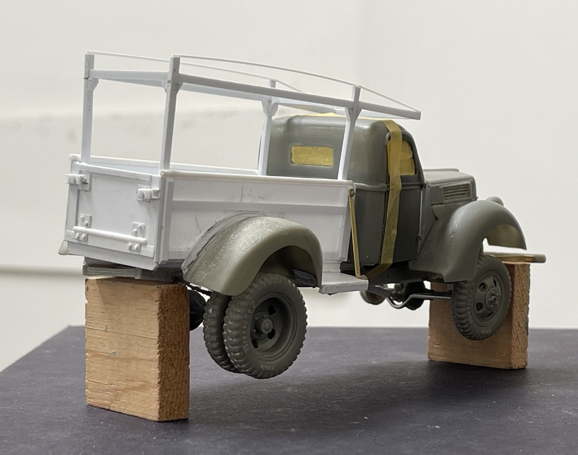
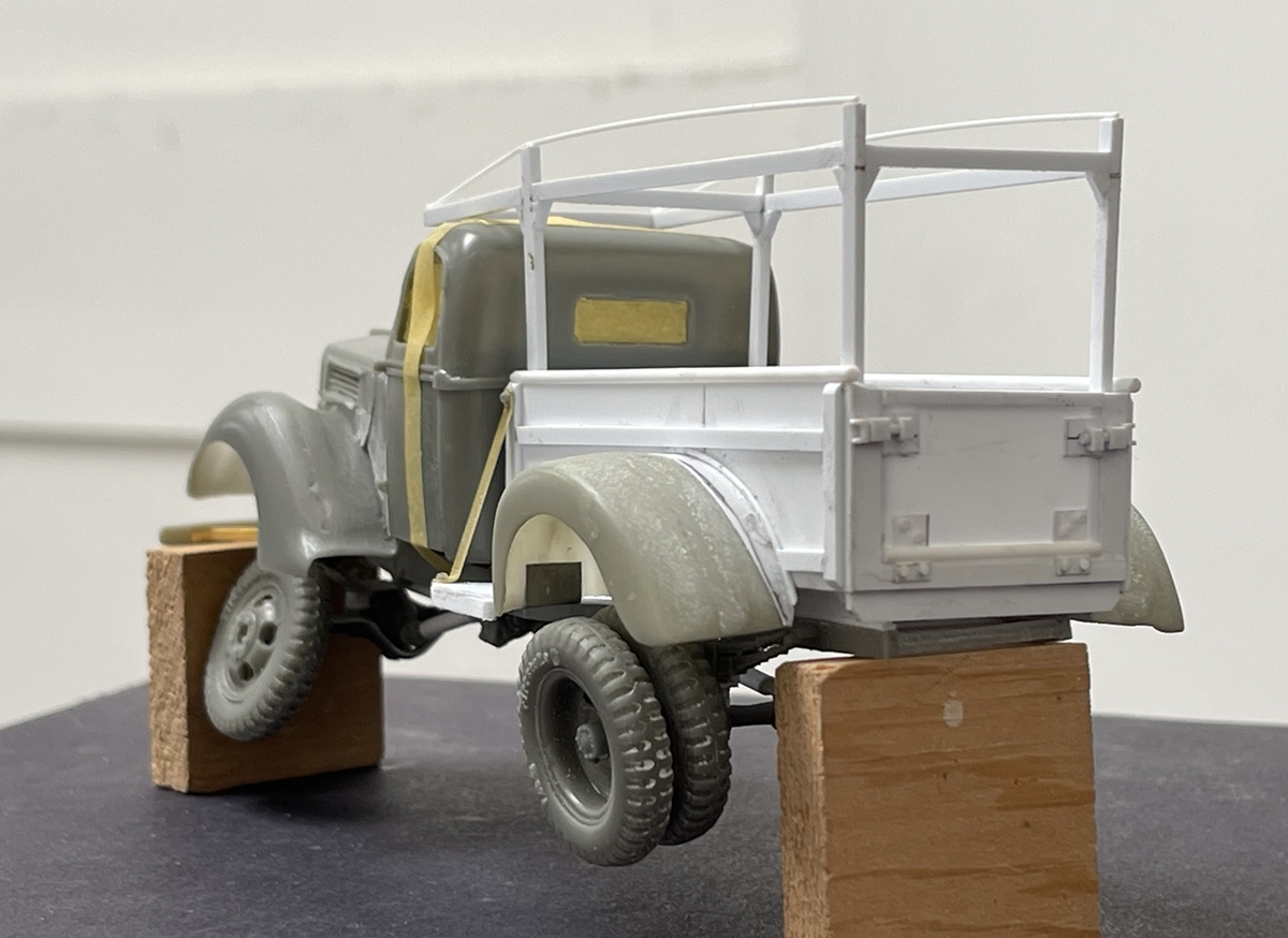
Well guys, back with some updates to the Ford, nothing too much, but enough to elevate it’s credibility as a build -specifically, the chassis still sags, but not as much as before:
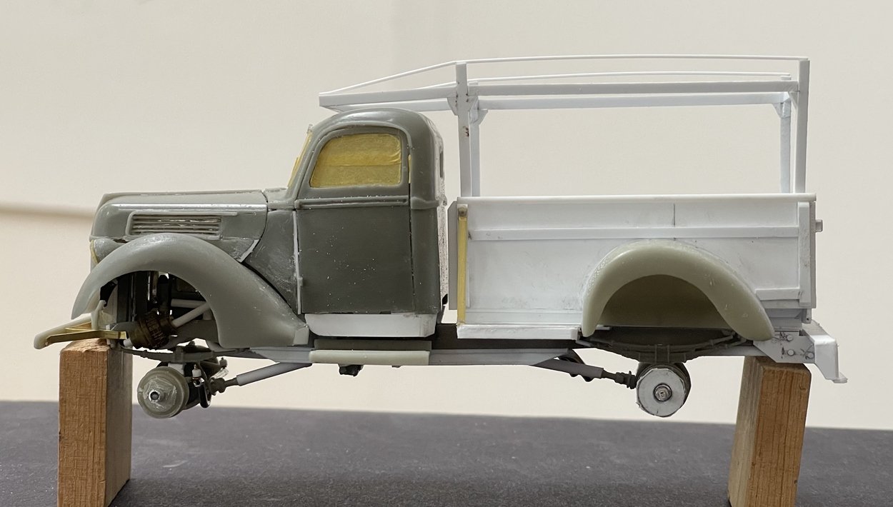
As you can see, at least on step back from the junk pile than the way it was. And, I added some body work here and there to fill gaps.
Not to worry about the wracked bed, as this is only dryfit - it will be squared up when its glued together.
To my relief, I am liking this build more and more. There are a few small parts to add, then off to paint. I’m thinking two tone, with the top of the hood and cab while, and the lower area a blue gray, then rust, scrapes, grime and so on. Even with the new and improved chassis, this is not destined to look like a show truck, as it simply has too many flaws which = bad for show truck; good for sacked out yard truck.
Cheers
Nick
9 Likes