So, I’ve been plodding along with this build for a few months making slow (even for me!) progress, but I’m just about ready to start the initial finishing and some final assembly (lower hull, suspension, tracks, and crew cab interior). I realized that I haven’t shared any of the work yet despite teasing that I would back when I was doing some early research.
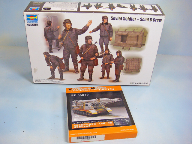
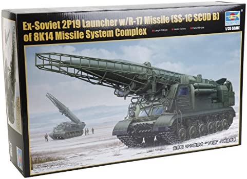
For the record, the kit is:
“Ex-Soviet 2P19 Launcher w/ R-17 Missile 9SS-1C SCUD B) on 8K14 Missile System Complex”
I won’t bother repeating any of the earlier research discissions and findings. I would just refer anyone really interested to this thread:
Soviet 2P19 SCUD TEL Reference and Research
The official Soviet and NATO nomenclatures for the launcher and missile can be confusing, and the research info was my best effort to clarify it all for myself. Hopefully it’ll help you, too.
I would offer once again that if you really are interested in the subject, you should go to the thread and follow the link to the research material on DropBox. it can be downloaded for free. The file is still there as of this post (02/02/'23), but that is subject to change at any time that I need the file space. Get it now while you still can…
I also won’t try to do any sort of “review” of the kit, Trumpeter Item No. 01024. Scalemates lists its release date as 2015, so the kit is well over 8 years old by now. Not too terribly long-in-the-tooth, but it’s certainly not bleeding edge state of the art. It has a few warts, but, so far, I’ve found it pretty much standard fare. It has some fantastic fine details along with some poorly done features, like mismatched locator pin and hole sizes, a bit of flash, etc. Certainly not a “bad” kit by any stretch, and I’d rate the majority of it is so far as “very good to excellent.”
One thing that can be said is that it is a whopping darned big box of parts. It can take a while to find some particular piece or part. Keep the instructions and parts tree illustrations handy.
Having spent most of my build time working on the crew cab interior, I can say that when compared to the references, it is a slightly disappointing mix of the early SCUD A, 8U218 launcher’s cab interior inside the later 9P19 launcher. I suspect that this is because there have been a number of quite thorough walk-arounds of the ex-Littlefield 8U218 Scud launcher done with almost zero coverage of the existing 9P19 launchers. This is too bad, but since almost no one knows or appreciates the detailed differences between the two, best to simply drive on doing the best that can be done with what is included in the kit. It “looks” right, and the major components and features, while different in detail, are essentially the same as far as I can tell. I don’t suspect that anyone will come up to me at some model show and attempt to point out any corrections.
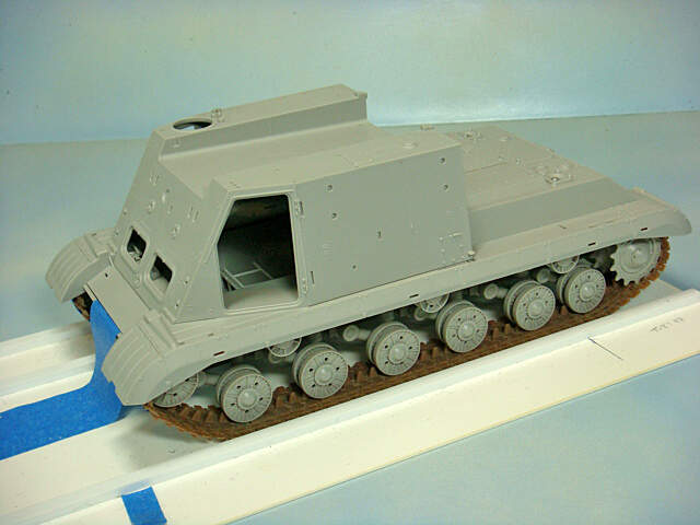
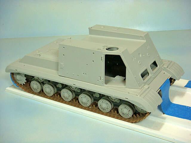
This is where I’m at in the build right now.
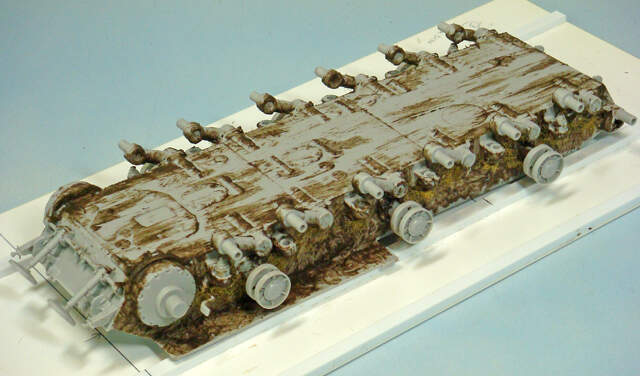
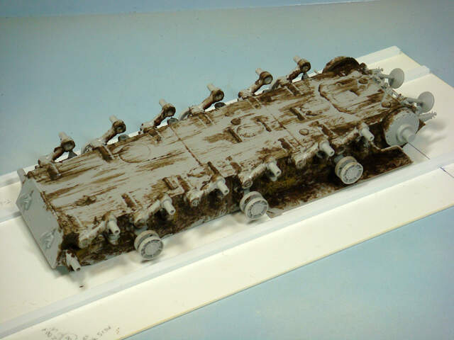
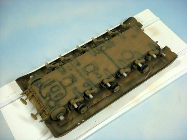
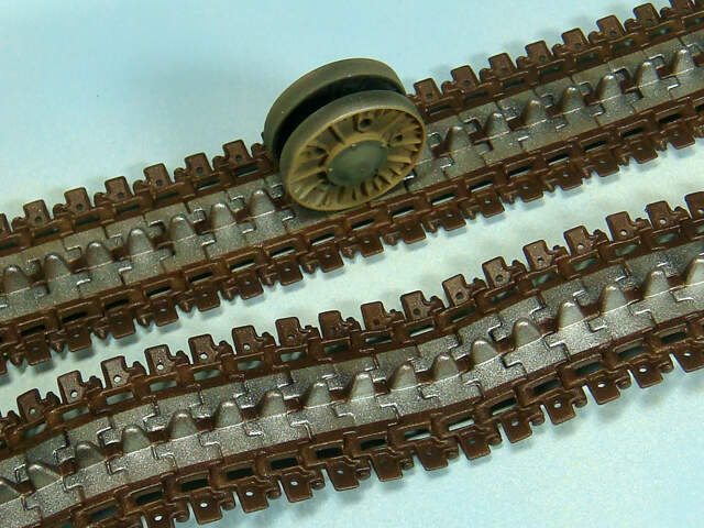
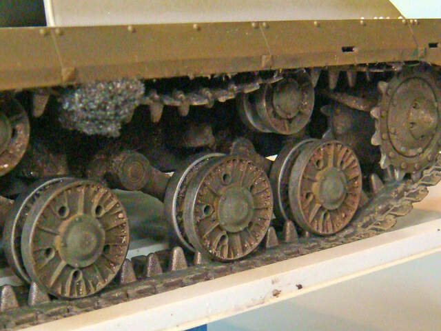
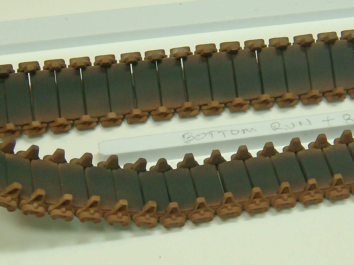
I started with the suspension and tracks.
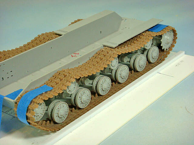
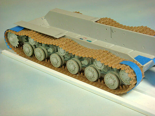
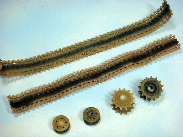
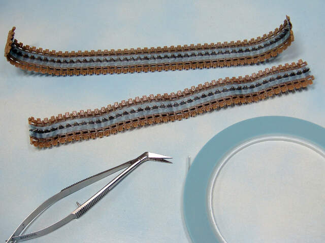
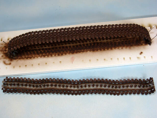
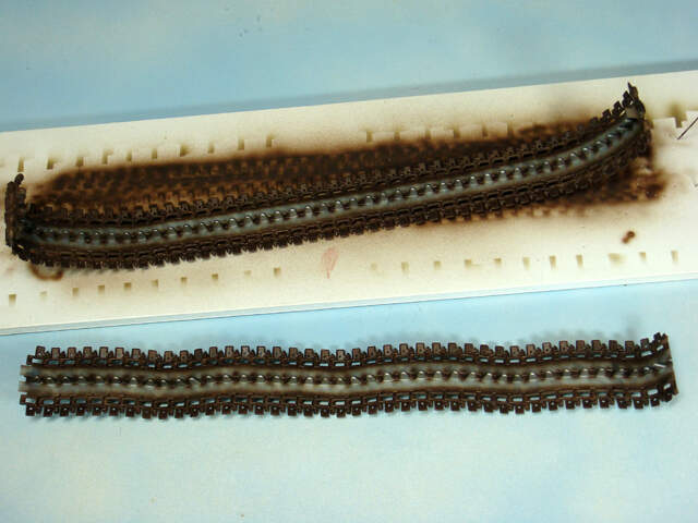
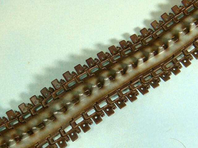
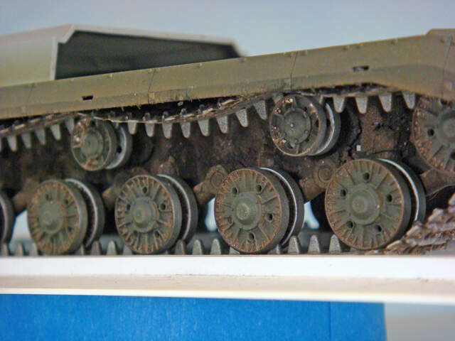
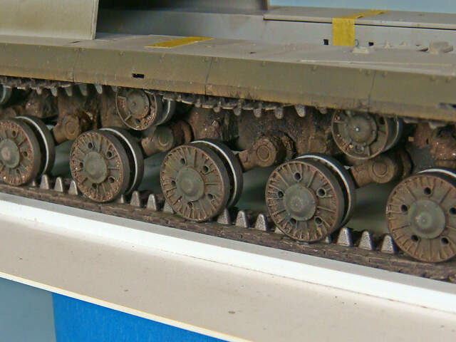
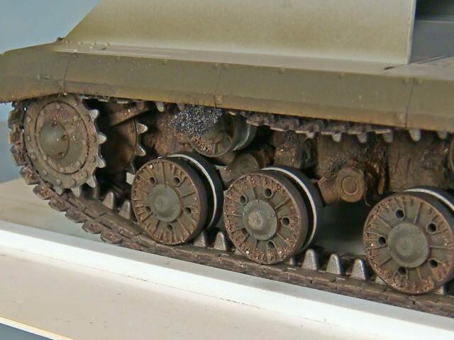
I advise a good deal of care and patience here. The kit tracks are link-to-link gluable styrene. Overall detail is crisp and the molding clean. There are specific left and right links, but unfortunately aside from the part numbers, the instructions don’t offer up any clear drawings. The difference is in the ends of the molded-on track pin heads. The flat ends go inboard and the ends with washer detail go outboard. I’d suggest checking some of the reference photo albums listed in the research materials to confirm the direction that the links face when installed on the chassis. The lower hull and chassis on the prototype are taken from the T10 tank, so that can also help with these details.
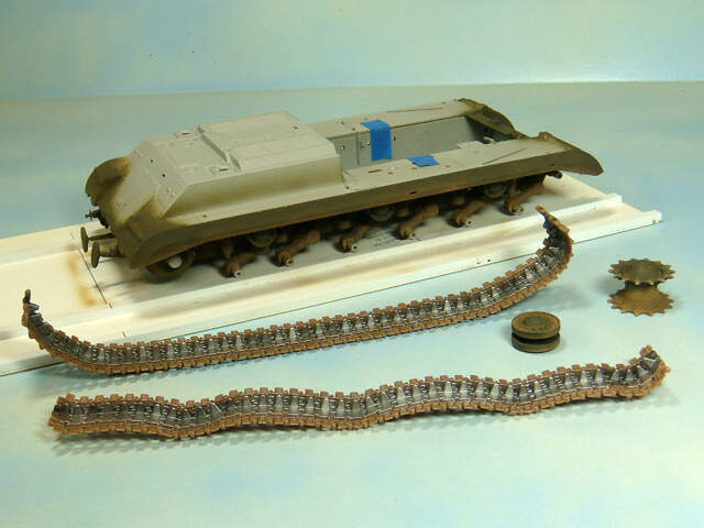
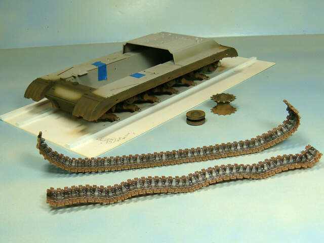
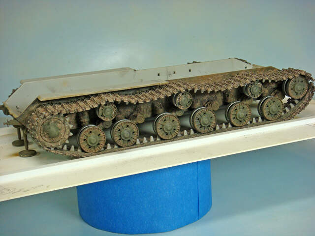
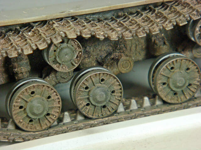
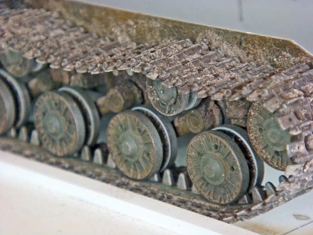
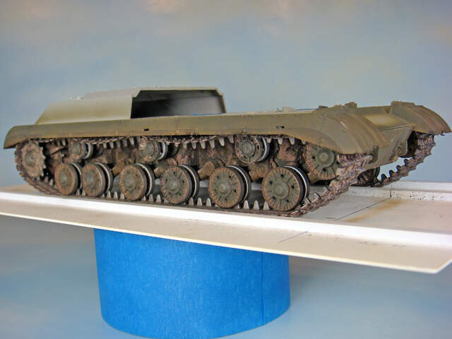
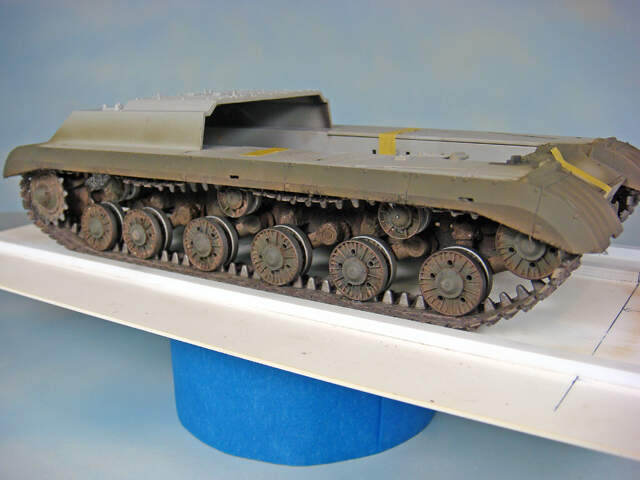
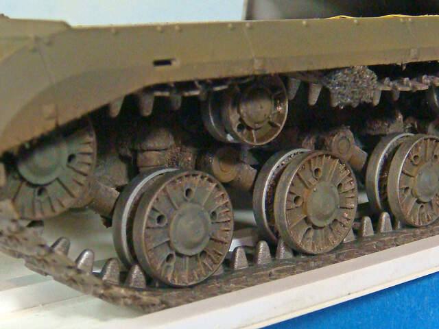
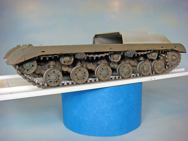
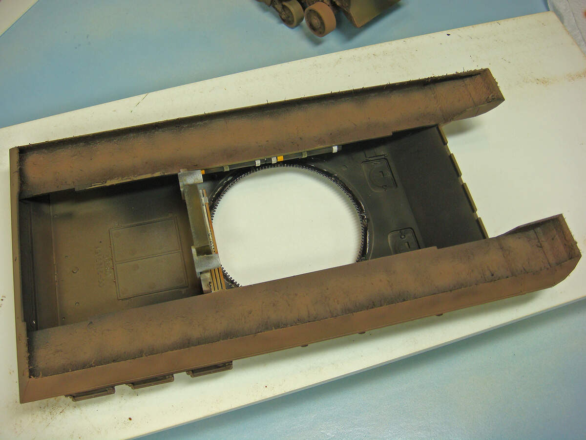
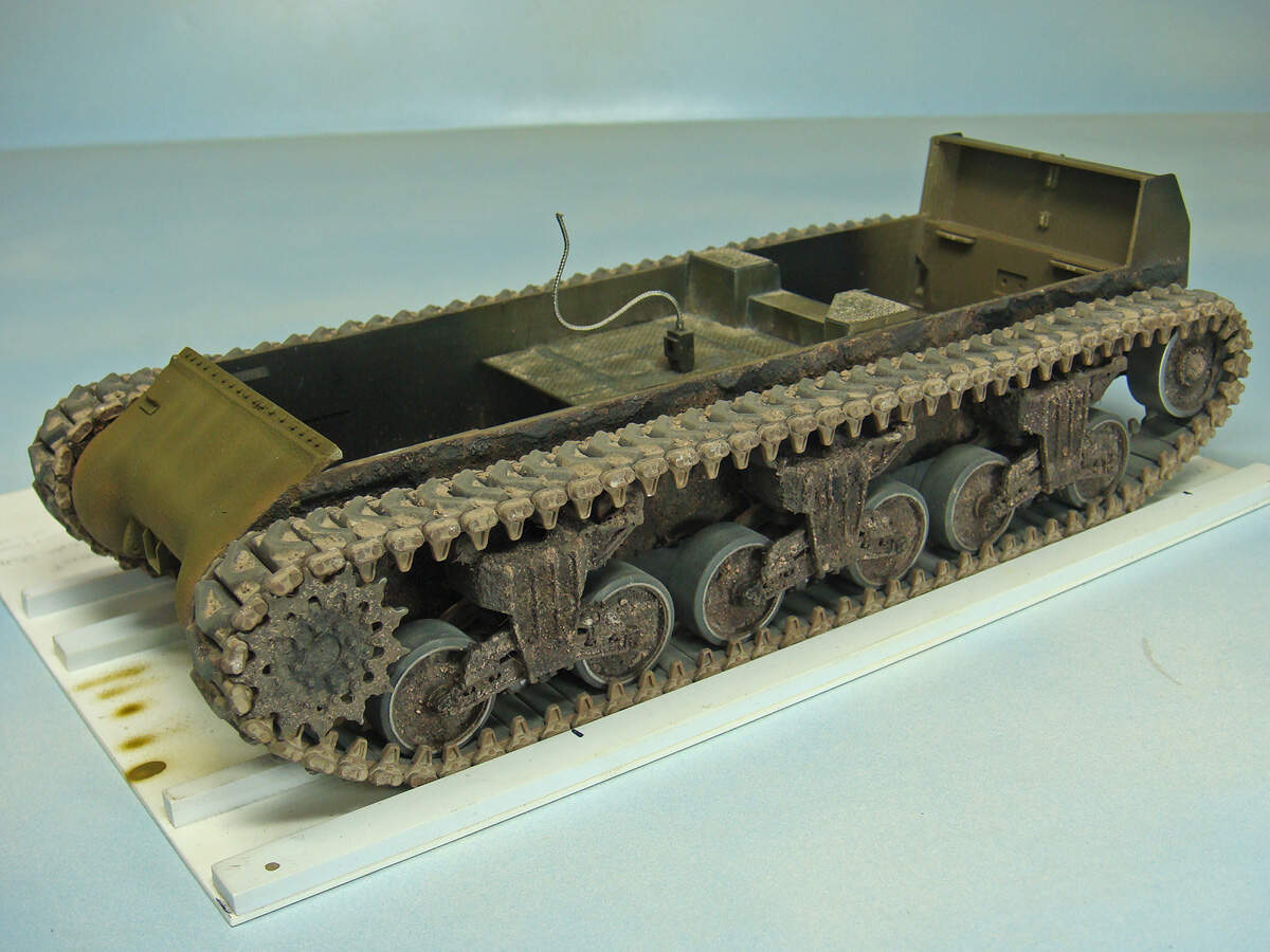
As usual for me, I made a quick alignment fixture to hold everything in place as I worked my way through the suspension. As shown in these photos, everything except the return rollers is only dry-fitted and will be removed for painting and weathering. It is necessary to finish the suspension before gluing on the upper hull since the design of the fenders will prevent installing the parts after it has been added.
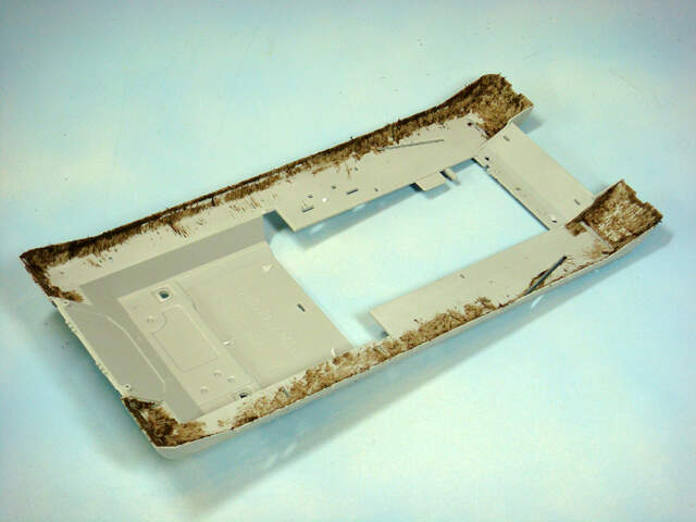
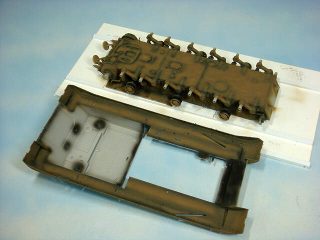
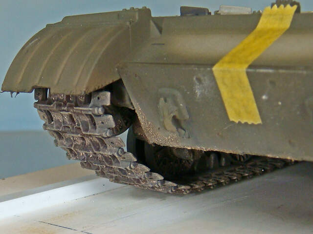
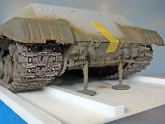
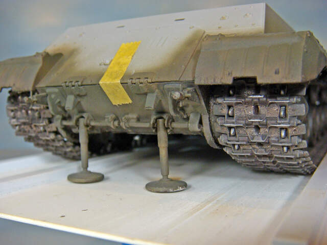
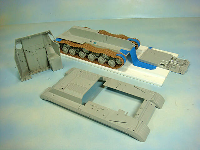
These photos show the upper hull and crew cab dry-fitted to the lower hull and suspension. To the kit designer’s credit, all of this fits very nicely and snuggly.
However, in order to paint and finish the lower hull and cab interior, it all needs to come apart.
I didn’t make any significant modifications to the upper hull part, mostly just some layout lines to help figure out where I wanted to run electrical wires, cables and pipes.
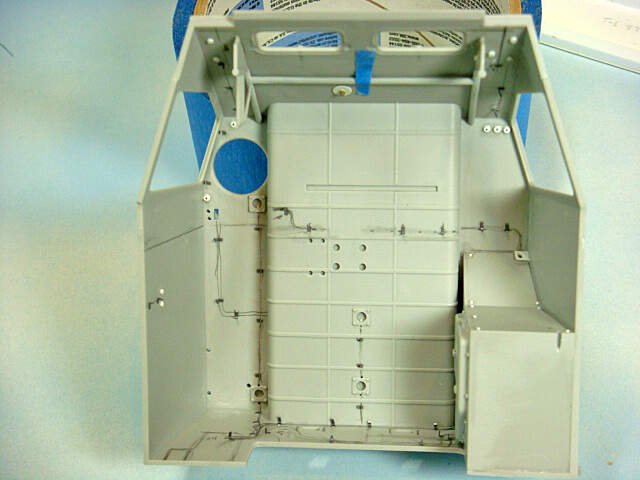
The crew cab interior will get a bunch of electrical wires and piping. All of these were laid out in pencil as I worked my way through the various reference photos of the two different cab interiors. In the main, the kit represents the 8U218 cab interior, so that’s also what I did with the wiring, etc. The boxed off area in the lower right corner holds the APU generator in the prototype.
I’ve also added numerous L-shaped pieces made from lead foil that will replicate the camps that hold all of these wires and pipes. This will allow me to paint the interior, install the wires and pipes, then simply bend the clamps over them. This makes installing these easy, quick and very clean. No need to try to paint these details against the walls and roof.
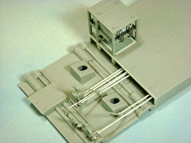
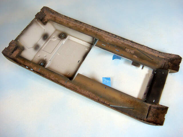
Trumpeter cleaverly puts most of the floor details on a single piece that works like a “module.” The references show all of the mechanical push-pull rods and other connectors for the driver. I had to cut out the vertical front wall of the raised floor section as per the prototype to lead all of these to the rear. The rack for the batteries is provided in the kit but it lacks the actual large storage batteries. These were made from styrene strip stock with filler caps punched from styrene sheet and cables made from lead wire. Again, all just dry-fitted here to be painted separately.
Note that the molded-on rectangle shapes on the raised floor replicate rubber mats on the prototype vehicles.
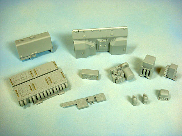
There are a fairly large number of interior components and subassemblies in the kit. These are just some of the more interesting ones. Not shown are the 8 crew seats, and a number of other small fittings. As you can see, I replaced the handles / guards on the control boxes and radio with brass wire and drilled out a number of connection points for the wiring and pipes. The kit also provides a bunch of decals for many of these dials and gages.
The large tank seen in the upper left of this picture is the hydraulic fluid reservoir. The hydraulic pump for the missile erector system is the gizmo next to the radio in front of the firewall.
Missing from the kit are the windshield hold-open arms, hinges and motors for the wipers. Fortunately, there are some decent pics of these details in some of the references, so I was able to do some simple CAD drawings and 3D print these little parts.
Here’s one of the windshield hold-open arms. The other is a mirror image.
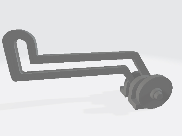
The windshields can be opened forward, and each has a pair of hinges.
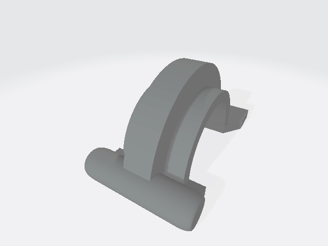
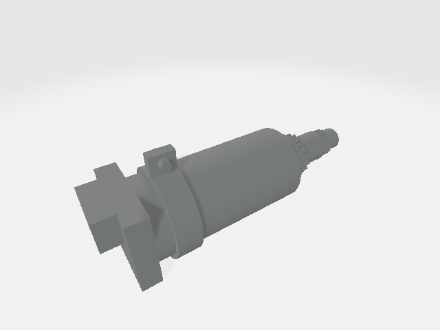
Finally, because the windshields can open and close, the wiper motors are made as separate units mounted to the front cab wall and connected to the wipers with flexible drive shafts. This is one of the motors (one for each windshield). The two parts are identical.
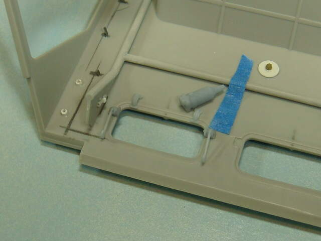
To give you an idea of where these parts go. Here the parts are just laid on the cab wall. I’ll add the hold-open arms and hinges before I paint and paint the motors separately.
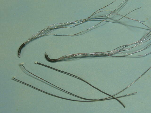
Finally, with all of this wiring, cables and pipes, I’ve had to make up some of the harnesses and wiring to test fit some things. Here’re a few of them. The rest will be added as the cab interior is finished.
So, that should pretty much catch up on the build so far. Just a couple of little bits still to make for the windshield wiper assemblies and then on to paint and finish of the lower hull and cab interior.
Happy modeling!