It’s a lot easier than it looks, and I know from your builds you have the skills.
In fact, now that I have completed other obligations I’m able to model for myself again.
Spent the whole morning (as I’m snowed in) removing more panels.
I sometimes find working on a kit is like building a cafe racer - it’s not always about what you add but what you take off.
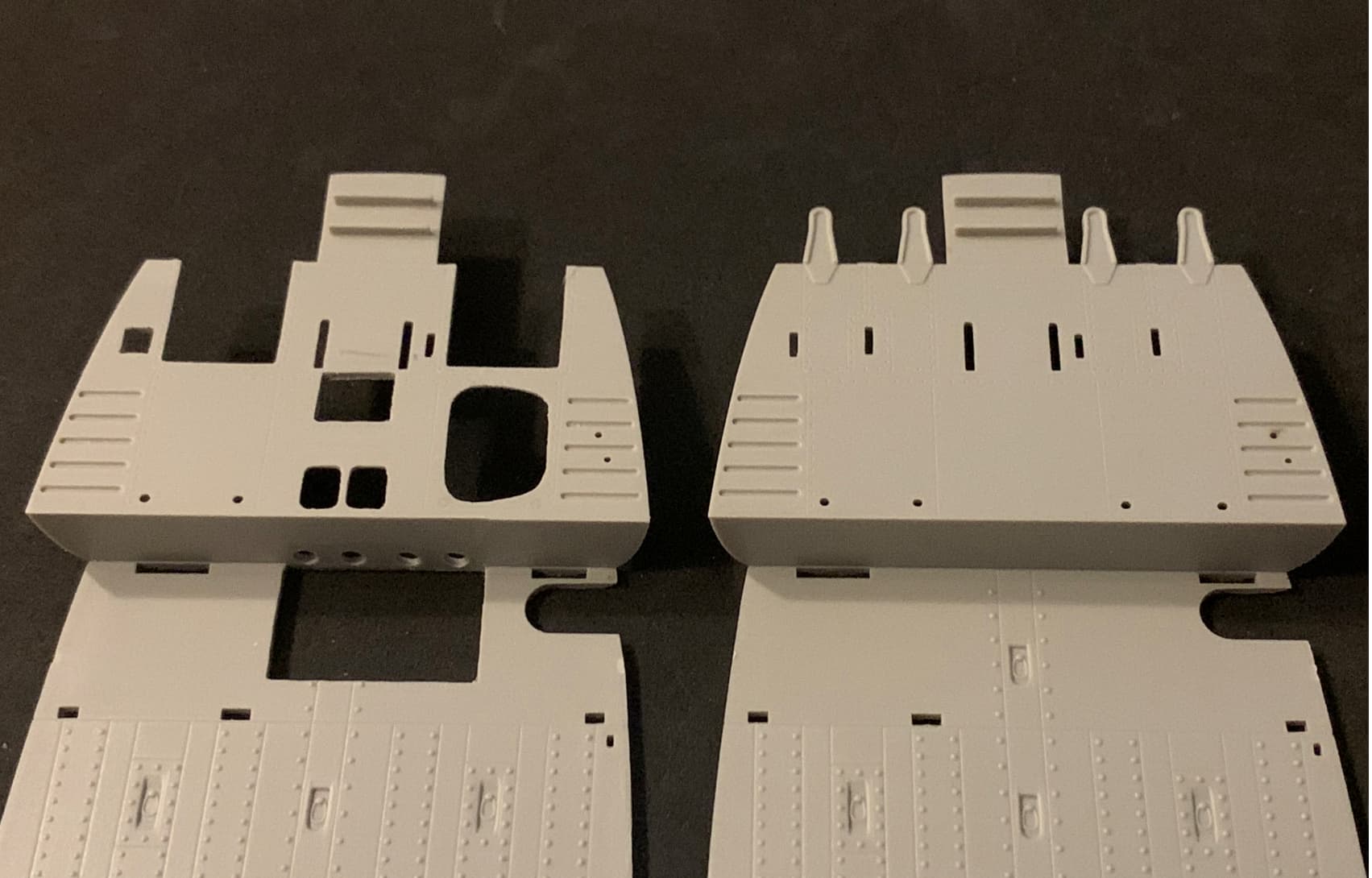
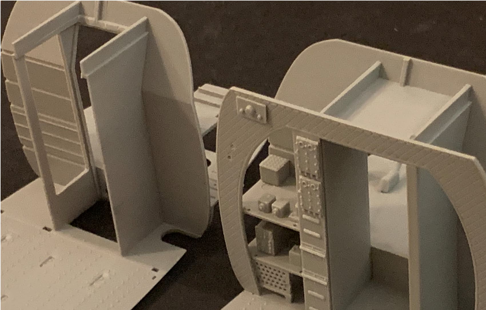
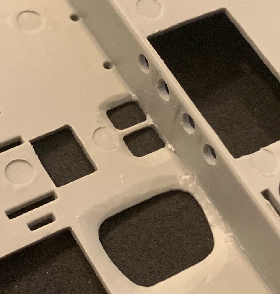
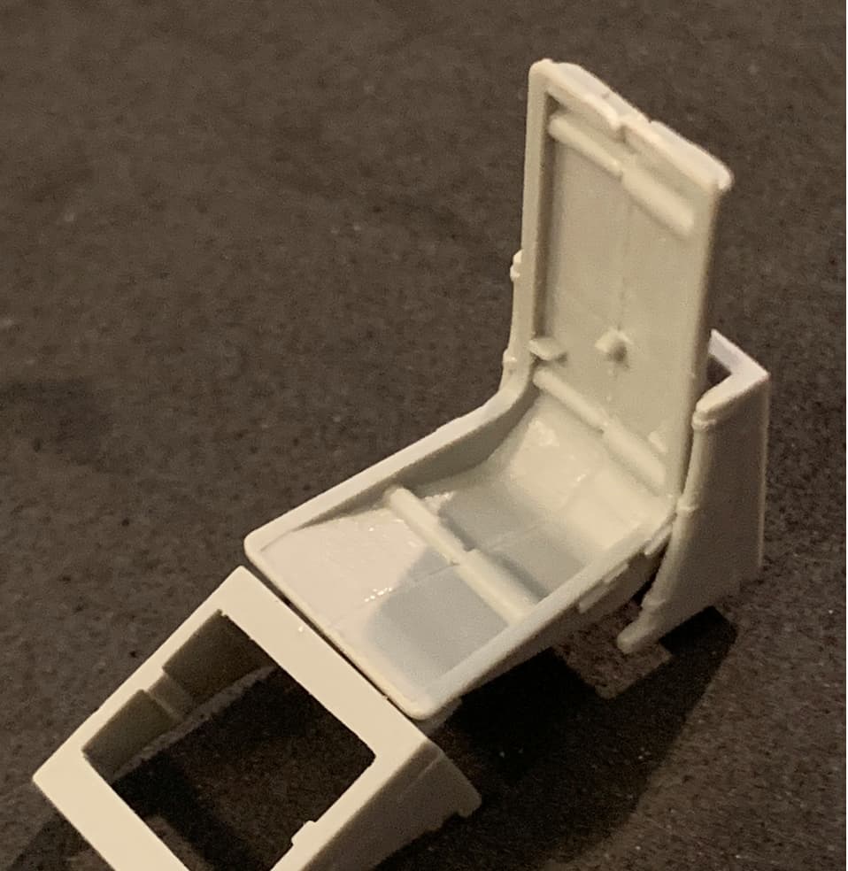
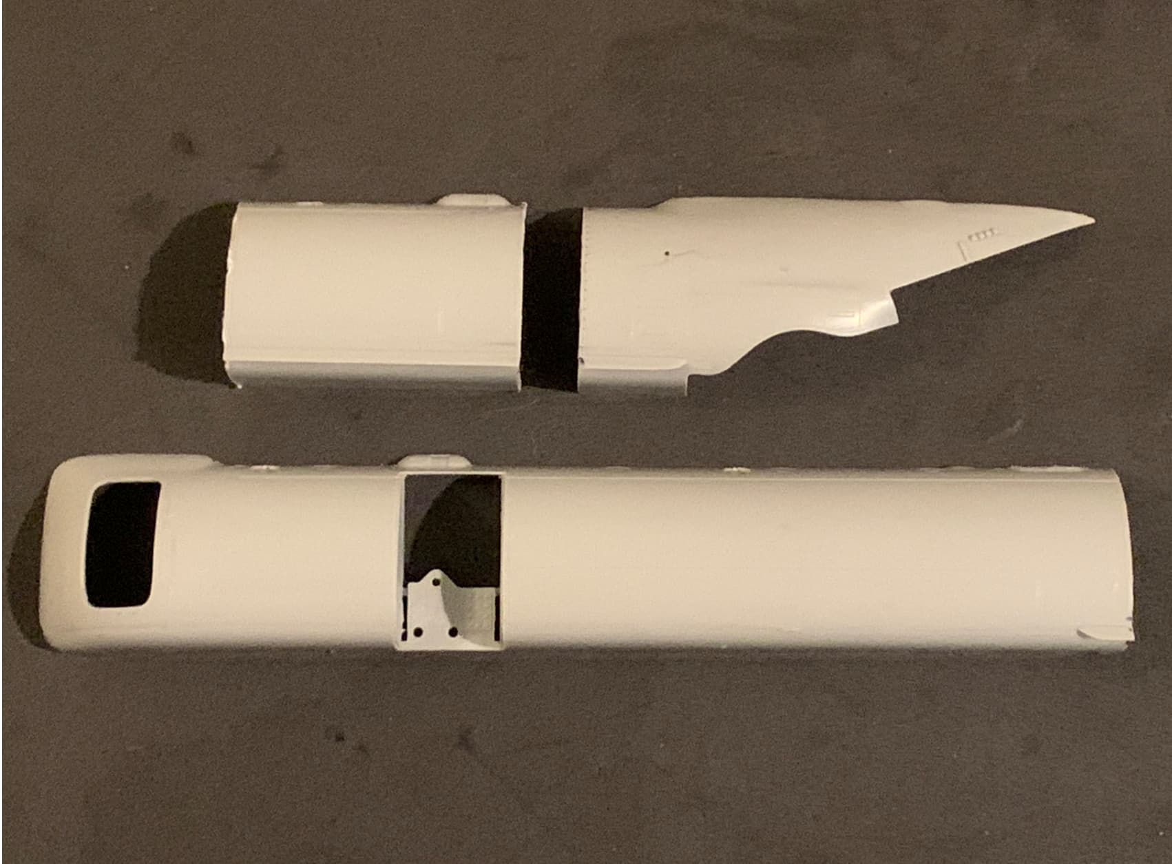
This is the cockpit and companionway before and after:
This shows where I removed a fictional ceiling section, and also an access door to the control rod pallet. (whole thing installs as a unit for ease of maintenance) There will be another solid bulkhead behind it, which makes the avionics bay somewhat fictional as well.
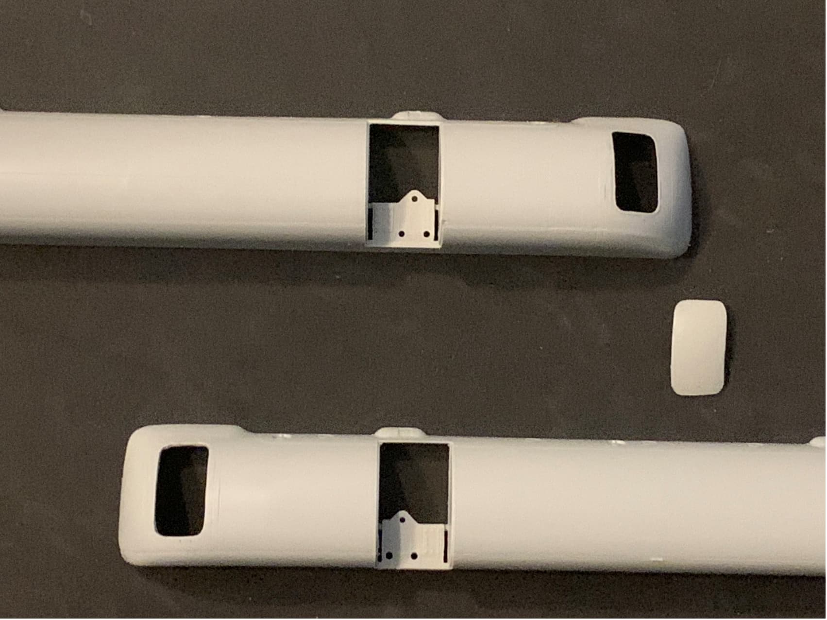
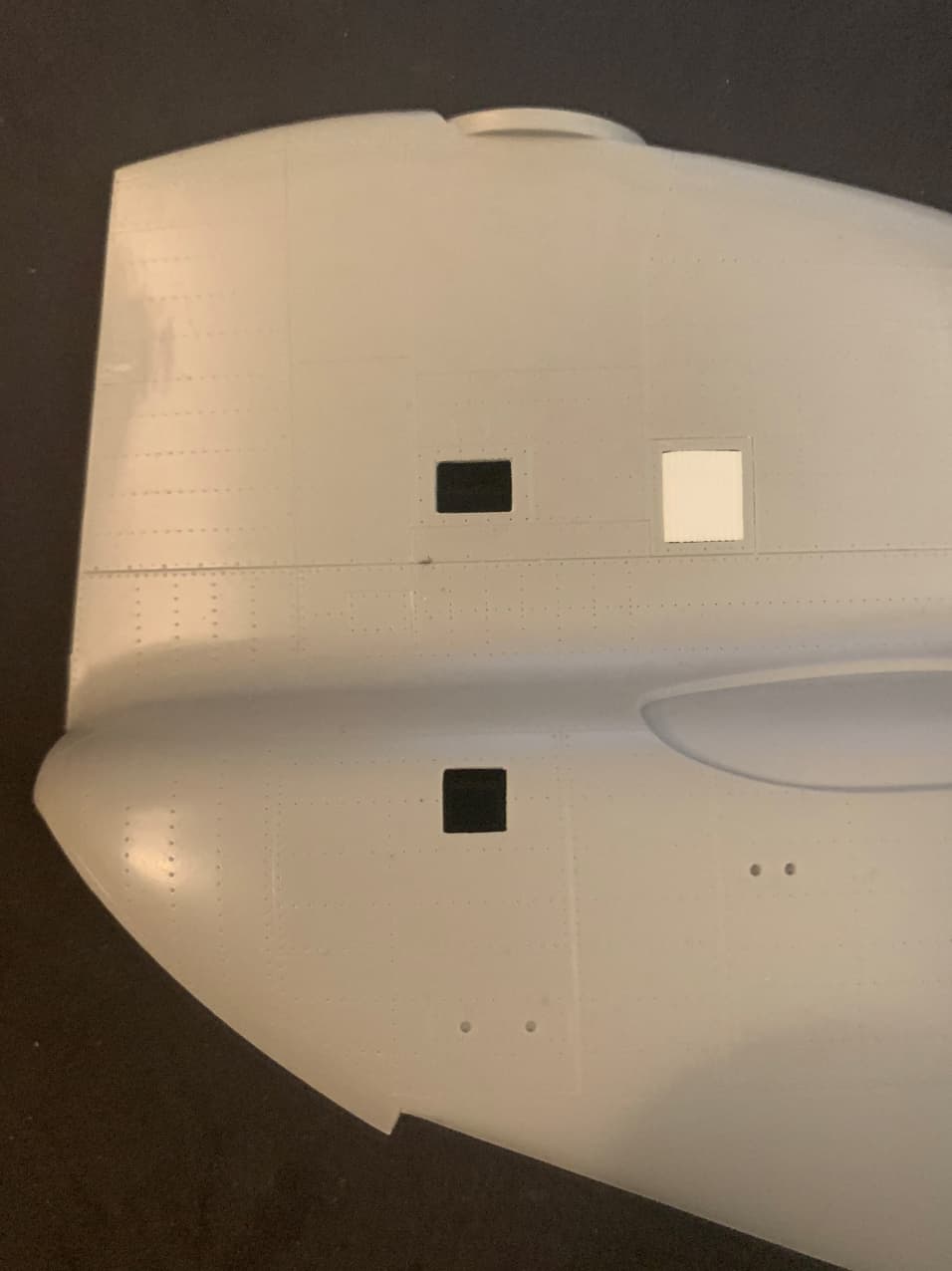
I also removed access panels from the fuel sponsons. Note the one on top - I did not cut all the way to the panel line but rather just inside of it. That’s because this panel will be fully opened. The outer edge of the opening has a rubber seal all the way around which will be represented by that thin area. The other sponson doesn’t need this feature as the access panel will barely be cracked open.
It’s not enough to simply open the panel. The plastic needs to be thinned from the inside to give the appearance of scale thickness, or at least as close as what’s possible.
I know all of these holes look a little rough at this stage but once I hit them with a file and a very slight amount of liquid cement they’ll all be fine.
I forgot to post the photos where I filled in the holes using the method I described in a current Saladin thread. Can’t even see where they had been. I won’t be placing a seat in that location.
Now I know to move the holes forward a bit and possibly make them a tad smaller.
Even if I left it as is I think it looks way cooler. But of course I’ll have to fiddle with it a bit more…
Great work. Wish I could do as well. Why do you refer to the ceiling panel in the companionway as fictional? TM 55-1520-240-23-2 shows a forward transmission drip tray installed there? Is the tray a later addition to the area than the model you’re doing?
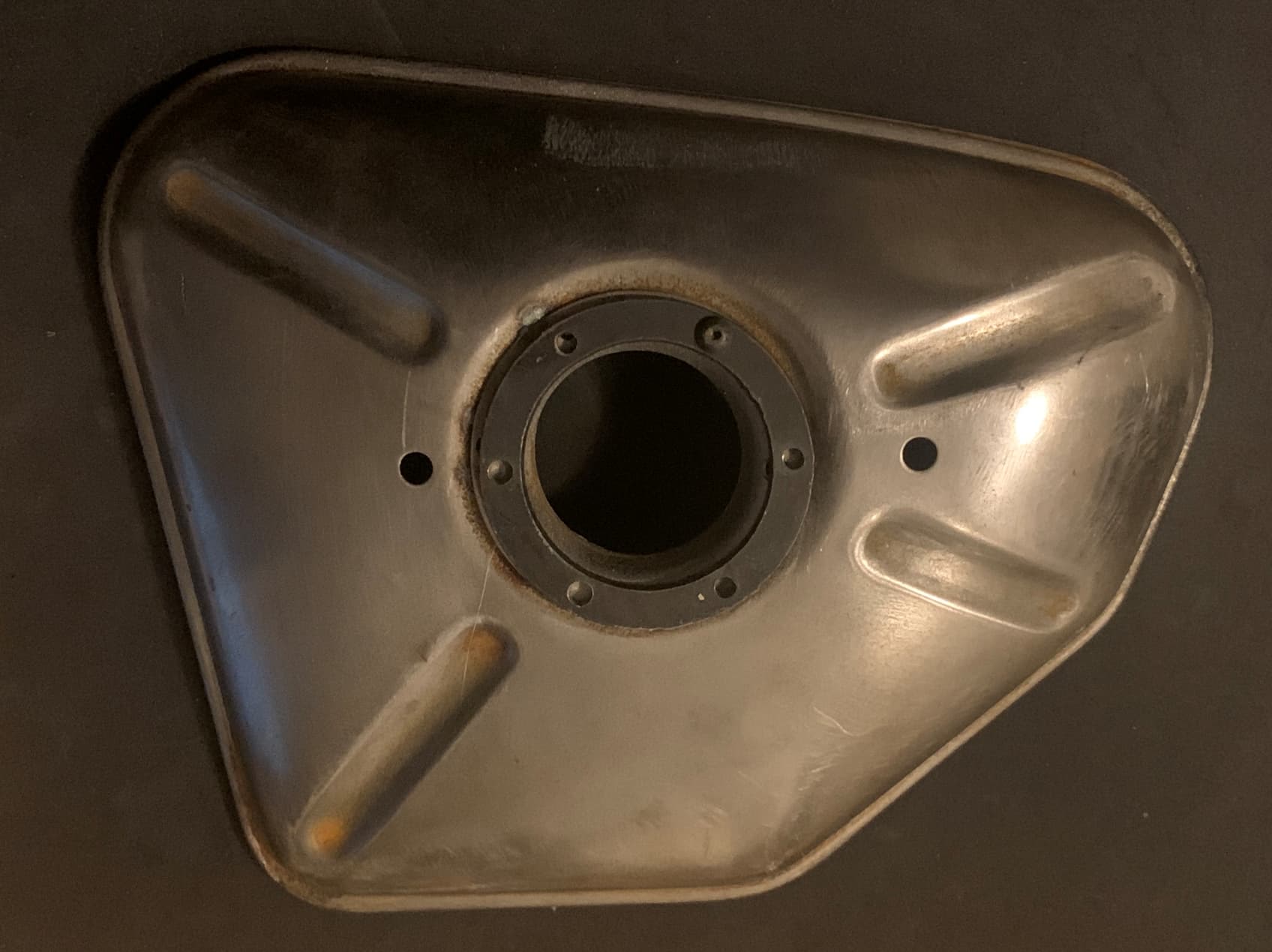
Perhaps I should have said fictional in its representation, as is most of that area of the kit. For instance, where is the fold down jump seat? At any rate, I’ve got a mechanic friend who wrenches on the current F models helping me out with the C model. He’s been a wealth of knowledge, as he’s worked on Sh*thooks going back all the way to the B model. The drip pan itself has a sort of X shaped stamping, kind of like the photo below, which is actually an airbox cover for a CB500 Twin. I’m using it to make a bitchin oil tank on a bike build, which will include a sight glass. I say this only because this project and a few current armor projects have hindered my CH-47C build somewhat.
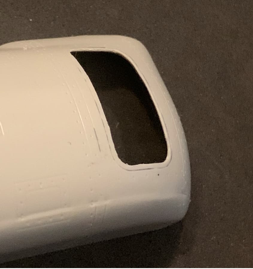
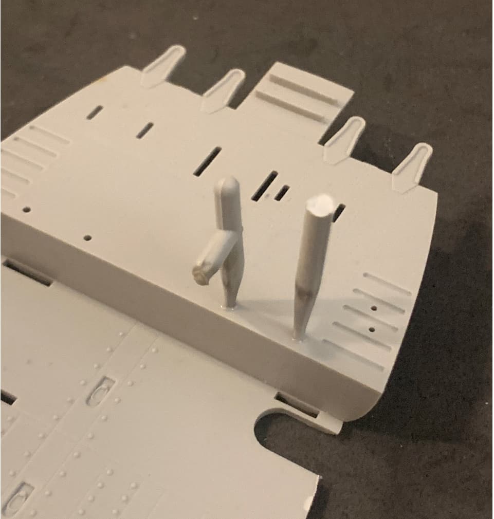
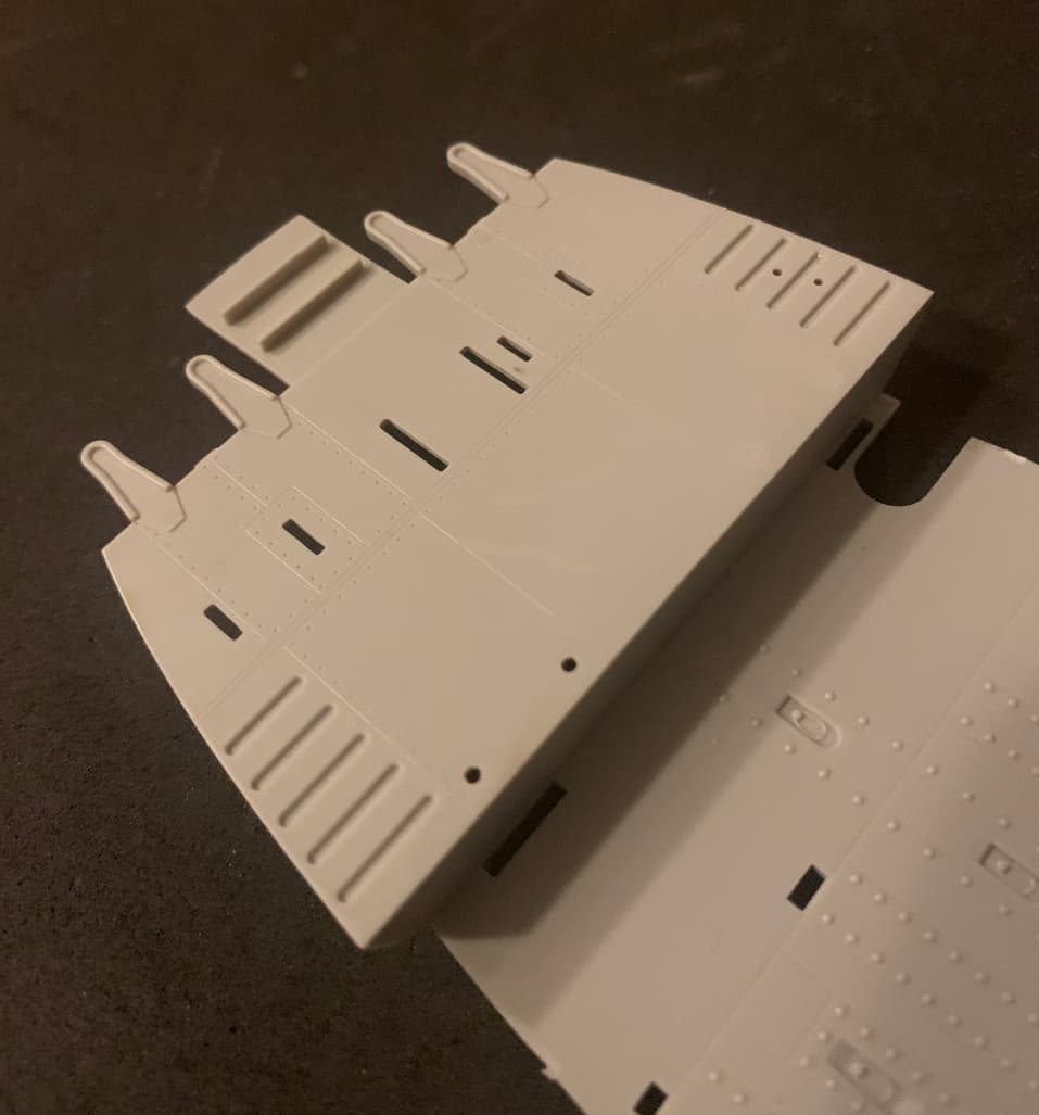
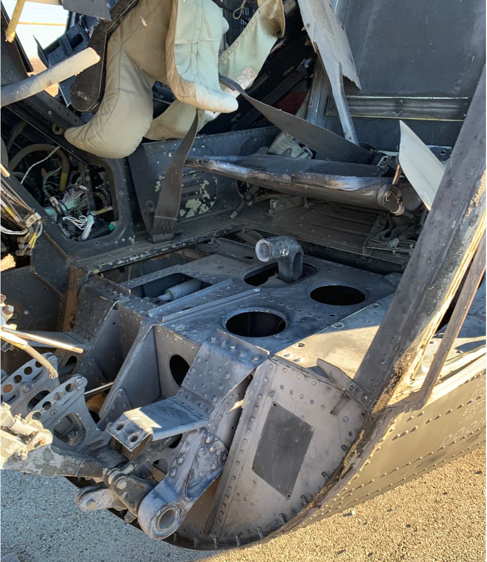
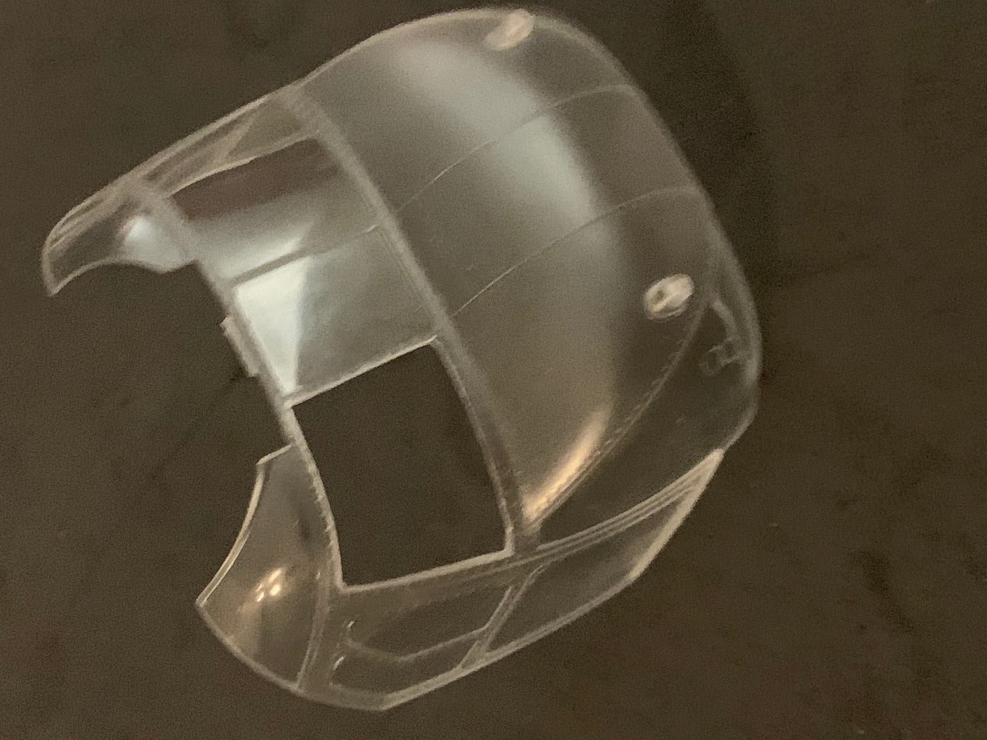
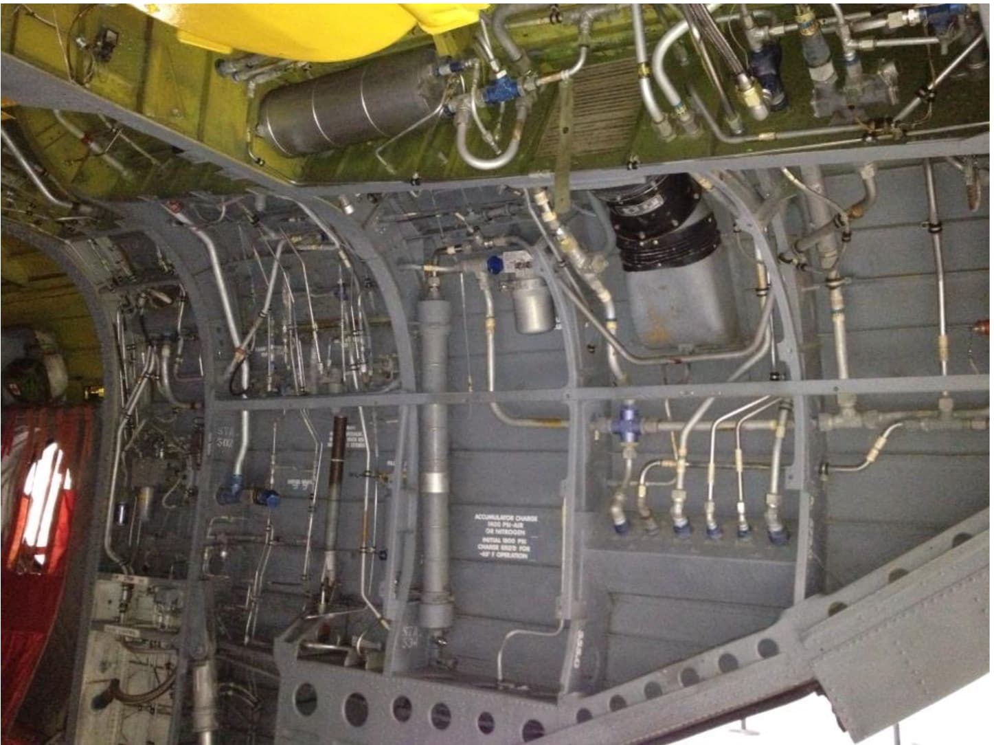
But since you’ve got me back into build at least momentarily, I’ll show another quick update. I’ve been wondering what was behind the lower square vent in this photo. That vent was there all the way through the C model. In the Trumpeter kits It appears on the A kit but not the D, so I had to cut it out myself:
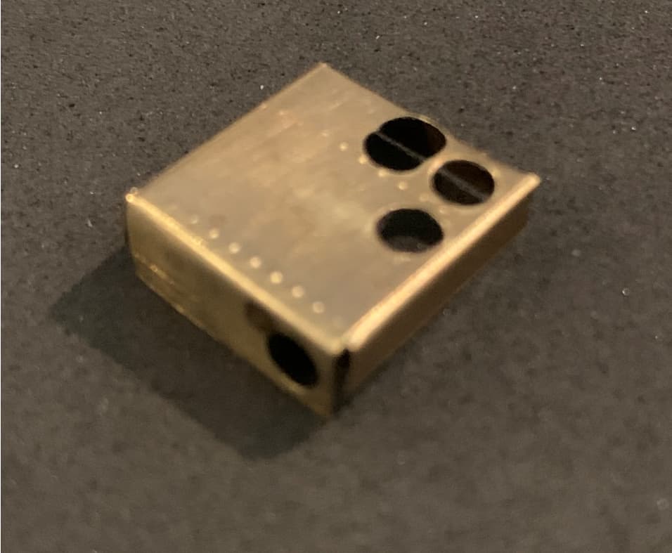
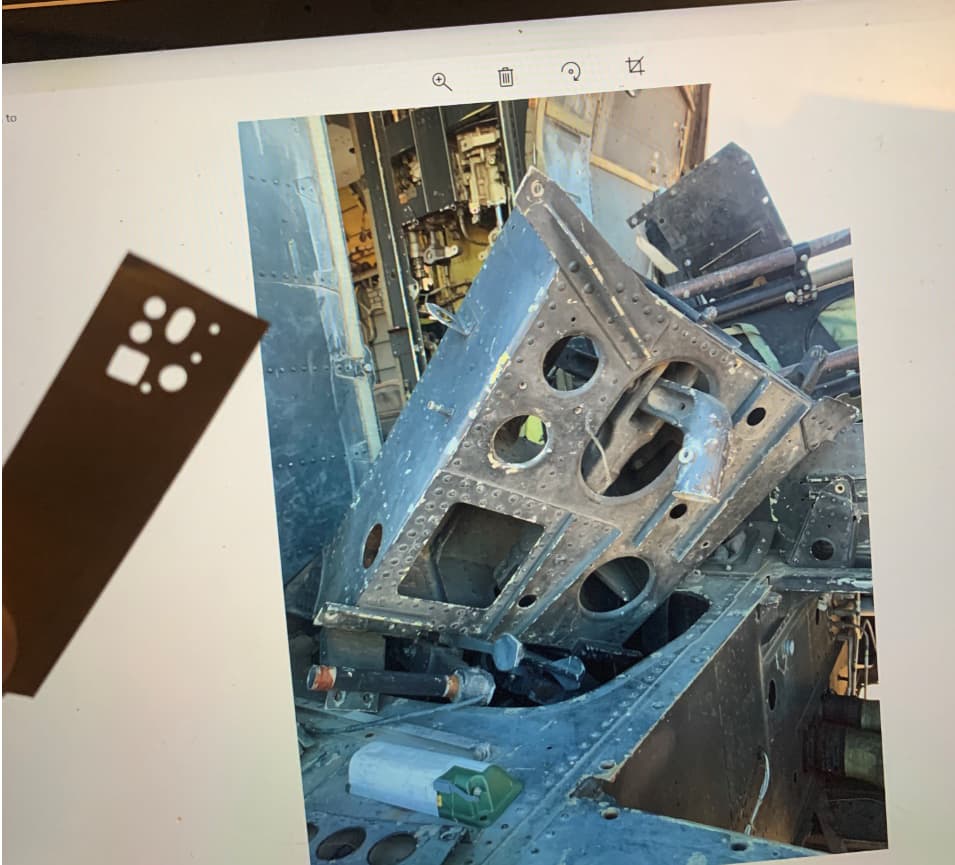
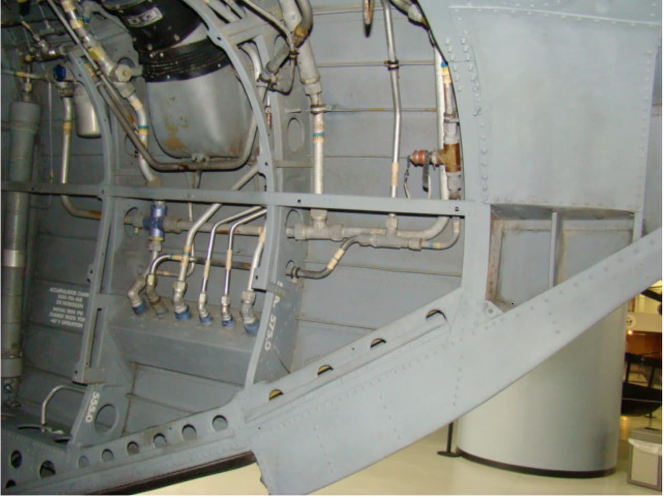
So finally (and this is another reason I haven’t posted in awhile) he provides me a photo of the blower - part of the Utility Hydraulic System cooling system.
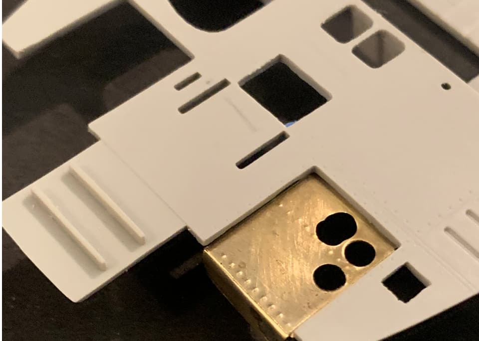
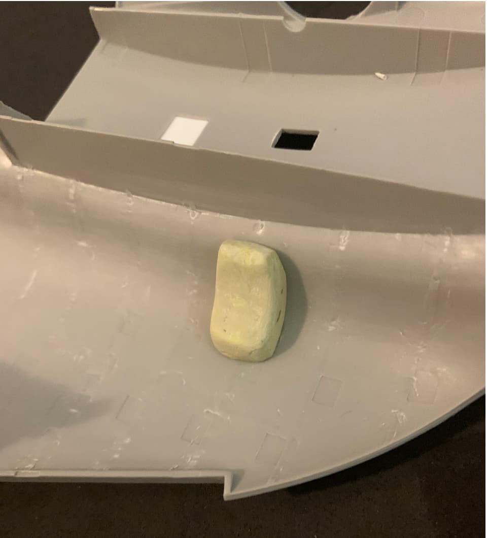
Three guess as to why that green strap is there in the first photo. At any rate, armed with this “new” info I can continue. First step in fabricating the blower is sticking a blob of putty on the back side of the opening so that after shaping it will sit perfectly in place:
Good to know. Could you ask your buddy to measure the width of the companionway? I think Trumpeter made it too wide by a couple of inches. Not a big thing, but it affects the shape of the two closets on either side. Would appreciate it. Is the green strap to flutter in the breeze when the cooling system is running?