One of my resolutions was to start reducing the size of my stash - or should I say the volume. One way to do it is build more of the larger kits that are taking up so much space.
And since there is no accurate CH-47C in any scale, I thought it would be perfect to get rid of a couple of more kits and build a CH-47C in 1/35 by kitbashing them.
It seems many of the more interesting paint schemes can be found on the C model.
I don’t think I’ll do the entire build in this thread, just point out what needs to be done for the conversion, as well as the flaws in each kit, as I’ve built both versions at least once before.
I may start this evening after I tire of yet another Twilight Zone marathon.
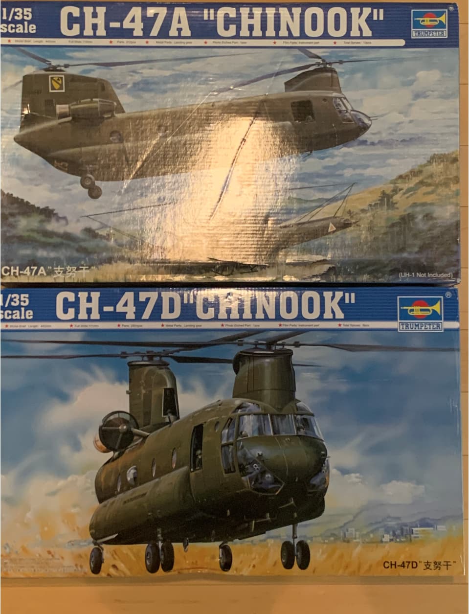
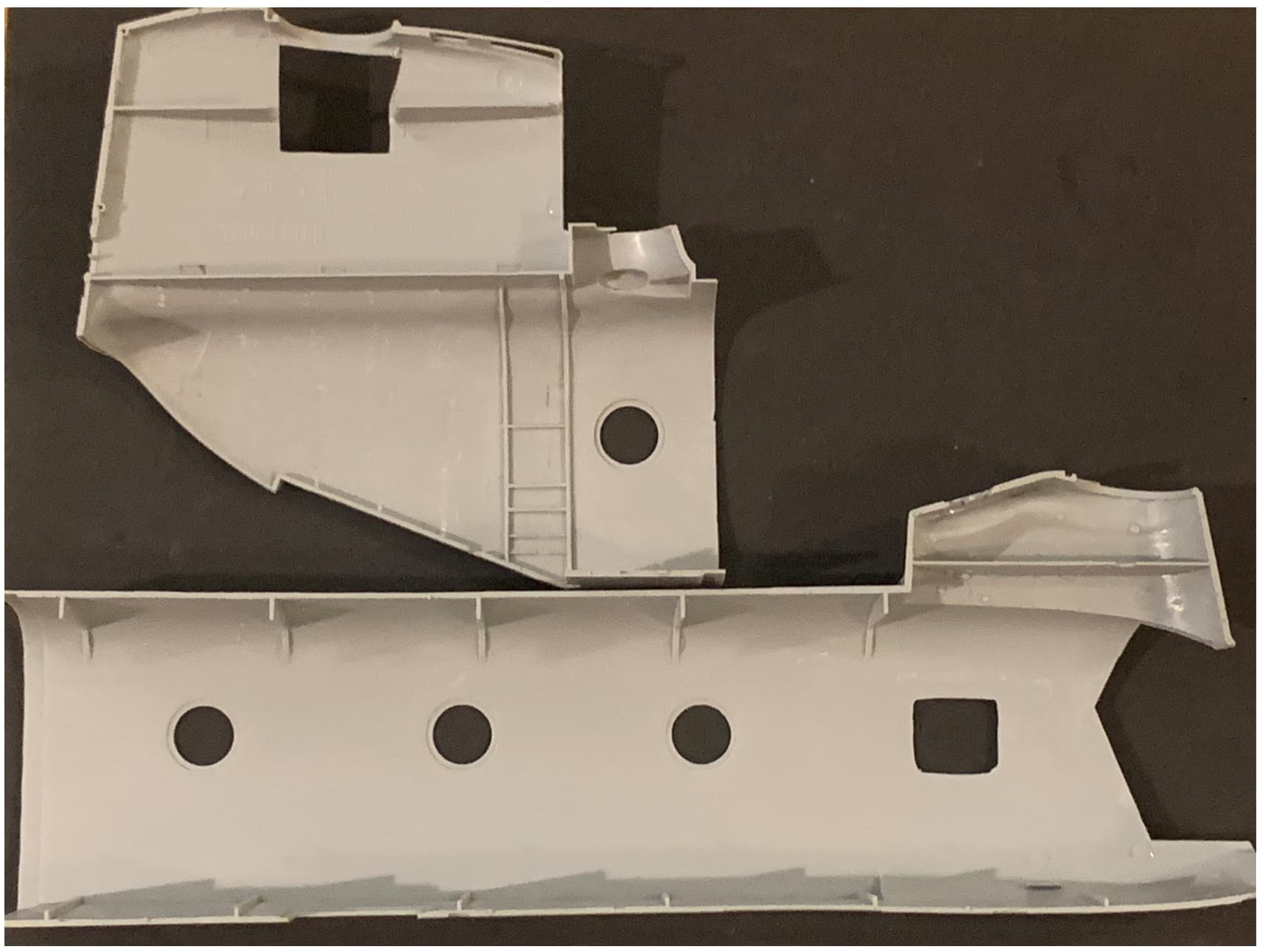
And here is the seemingly obligatory photo of the kits used:
I have the “A” model and intend to convert it into the ACH-47A. I am needing the long out of production (and really hard to find) Cobra Company CH-47 Cabin Structure Detail Set for all the stringers and and such. I have had this in my stash for several years now.
Please post a build thread. I’m getting through the Kitty Hawk SH-60B and would like to see a good comparison between the kits. What interior details does it come with…engines?
That’s a very interesting choice rather than just building a plain vanilla A model. I had considered it once, but without actually photographing the one at Redstone Arsenal I’m not sure I’d have enough references to do it justice. I should have done it when I visited the US Army Aviation Museum but I was under a time constraint. Might make a nice day trip…
I’d like to see what you do with it.
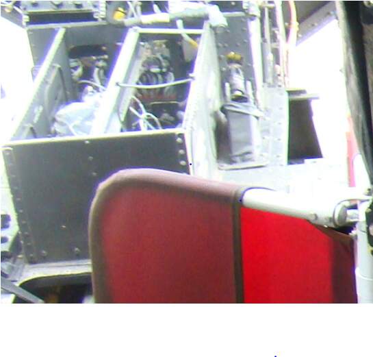
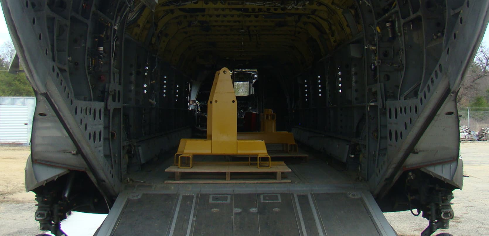
Both the A and D models have so-so interiors. The detail underneath the floor space up front which is clearly visible is nonexistent. Cockpit interior is, well, it’s there… The most disappointing area is the power distribution panels which are too small, ridiculously misshapen, and have fictional detail on their faces.
Eduard makes pre-painted faces for the panels but they are designed for the undersized kit pieces, and are poor representations. Like putting lipstick on a pig.
You get a cabin space heater. Again, minimal detail, and the walls of the closet are devoid of any detail.
The cockpit passageway lacks soundproofing, which is odd, because nearly every other surface of the interior had it. Even so, it would have been nice (and easy) to have had a separate access panel here, Again, much visual interest in that area.
The shelves on the left side contain a few pieces of avionics equipment. It’s not well done, but for this area I’d usually be prepared to be a little forgiving - the only only way to really see this area is by looking through the rear of the fuselage, or obliquely through the main cabin door. But if you plan on removing the port side window panel as I do then it becomes very visible and needs a lot of work.
The cargo area is pretty much covered, rather incorrectly, with thermal/acoustic blankets. The problem is that if you want to show any interior framework (which must be scratched) then you either need to cover all that detail with very thin sheet styrene or sand all of the detail off.
Finally, the ramp area attempts to portray some framework detail, but it’s better off removed to add your own if you want to portray it. Not only is it not deep enough - its’ evenly spaced, which is not the case on the real thing. Plenty of opportunity to make the kit shine here but it’s all on you. Again, Eduard makes a detail set for this area, but the sheet metal parts are pretty much correct, so that when added to the incorrect framework it really looks off.
Both kits come with engines. I’m not using them on either kit. They’re okay buttoned up. In display mode be prepared to get out the thin solder and wire.
That’s probably more than you wanted to know, but just my musings as the KC/Cincinnati game just got tied up…
Another issue is the rear ramp. Trumpy has you build it as two separate parts, an upper and lower portion. The actual ramp is one-piece, with the upper section retracting into the lower part.
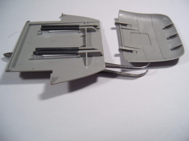
Here is a post I did a bunch of years ago (2006!) when it first came out and I was playing around w/the ramp on the A model to see if I could make it retract.
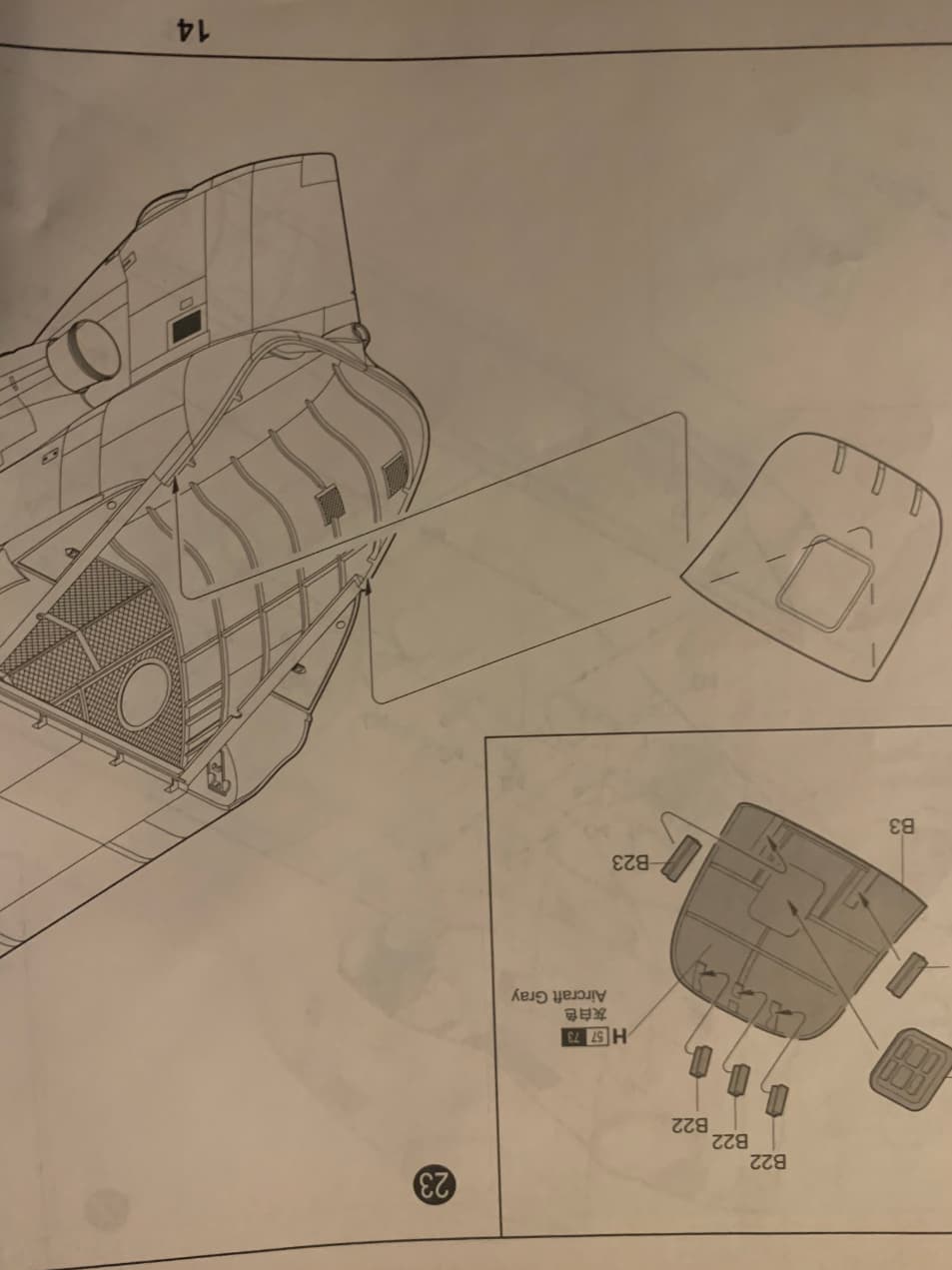
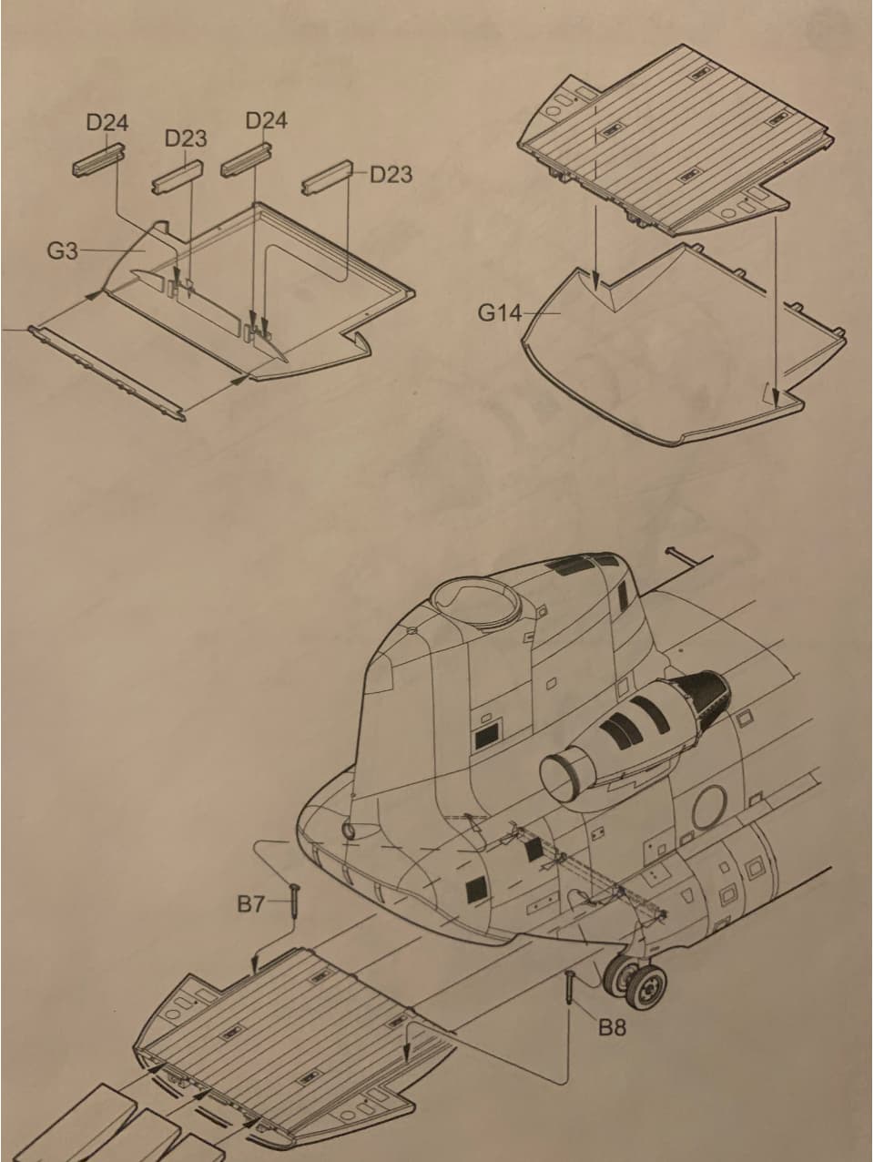
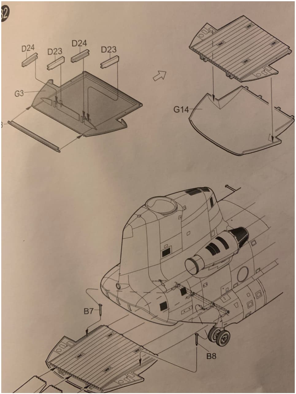
I started testing to see what it would take to get the upper ramp to retract into the lower one. It was actually pretty simple. Trump provides most of the parts. In step 23, you attach parts B23 to the upper portion. In step 32, you attach parts D23 and D24 on the lower ramp. These parts make up part of the track that the upper ramp retracts on. By modifying them and adding some track inside, you can retract it just like the real thing. I first positioned parts B23 so that they stuck over the lower edge of the upper hatch by about 1/4". On the lower ramp is most of the work. On parts D23 and D24 for the inner rails, trim them about half of the way back to the curved cross member, angling the ends at a 45 degree angle with the longer parts going toward the ramp deck (G3). For the outer D23 and D24 pieces, they also get trimmed to a 45 degree angle with the longer part terminating almost at the edge of G3. Next, I trimmed down the curved cross member to the height of parts D23 and D24 so it would not interfere and removed the tabs sticking up between the track made up by the D23 and D24 parts. Lastly, I extended the tracks back with “T” shaped Plastruct beams and elevated them with 3 pieces of .040 sheet styrene as shims to raise them slightly above level.
You can see the results below. A perfectly retracting upper rear hatch.

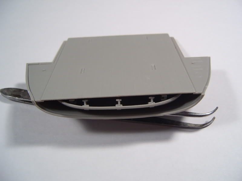
Unfortunately, I never completed it and ended up selling it a few years ago.
Well I would have mentioned that when I got to the instructions in my build, since that’s truly one of the worst mistakes made in instructions in quite a while. Since you didn’t I will, but thanks for jumping in…
The instructions would have you cement the ramp extension up underneath the fuselage - a situation that would never occur unless the ramp were fully closed:
The instructions don’t ever show the where the extension actually goes into the ramp in either of these images, although they do show it placed up underneath - an absolute impossibility if using the drive on ramps as shown:
So anyone unfamiliar with the ramp would assemble the kit incorrectly. In fact, I’ve seen a pretty decent build online where there modeler fell victim to this very mistake in the instructions.
Personally I found the feature a bit of gimmickry, much like a recoiling barrel on an SPG. and didn’t expend any effort on it on previous builds, Either you button up the ramp of you leave to extension inside the ramp.
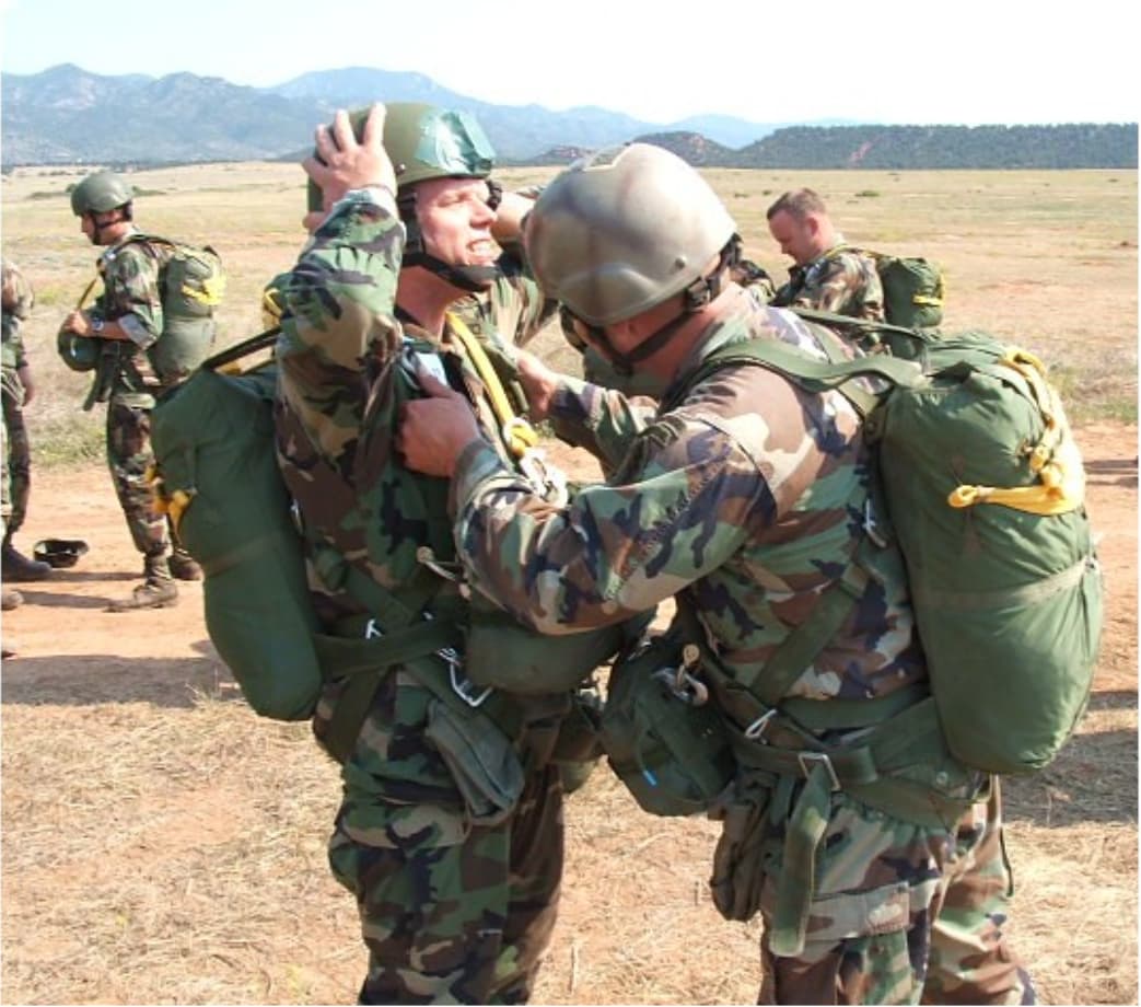
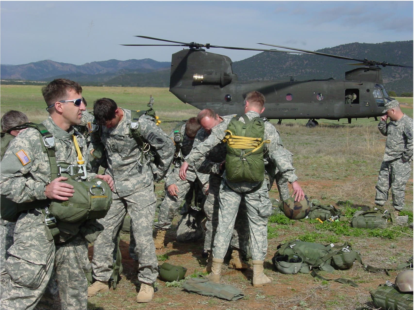
Most jumps I ever jumpmastered the ramp never went up during the entire flight, and I spent most of my time camped out behind the ramp hinge conducting outside air safety checks.
Ah yes, those were the days…
Pretty much exactly the information I was looking for. Thanks!
You’re welcome. While this wasn’t intended to be a review of either kit, you did ask and I’m happy to oblige. It’s been quite a while since I looked, but I don’t recall several of my observations being addressed in the reviews I’ve seen, although the PDP issue was obviously noted by one aftermarket company who makes suitable replacements.
Don’t let my comments sway you though, It’s still the best kit out there in any scale in my opinion. Offerings in other scales have their own inaccuracies and the heavy panel lines border on toylike in many of the offerings. That said, one of our members named Nacho Lilo did a very fine build of an MH-47 in 1/48.
So which variant are you interested in? The A model has dual rear wheels which were only seen very early on in the Chinook’s career. The D model suffers from a misshapen rear pylon that can be easily remedied with a bit of work. I’ve not seen any mention of that either, but it’s a quick, easy fix. I’ll address that issue as well as a few barely noticeable glitches as I start, which I hope to be soon.
Once you’ve procured both kits you get to decide which one to use as a base. The fuselage doesn’t matter, but the rear fuselage/rear pylon pieces do. The C model’s rear pylon is a combination of the forward part from the A model, and the rear, blunted part from the D model. I find it will be easier to cut the front portions off of each model, and add the C model’s front access doors to the D model pylon.
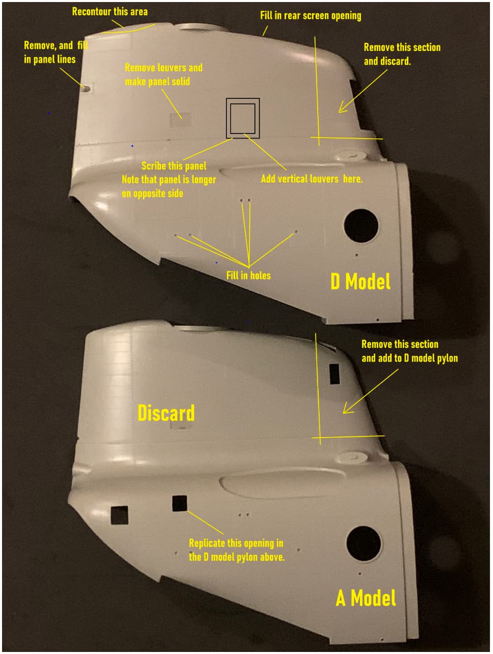
There are two screen openings above the APU exhaust port you’ll also need to fill in.
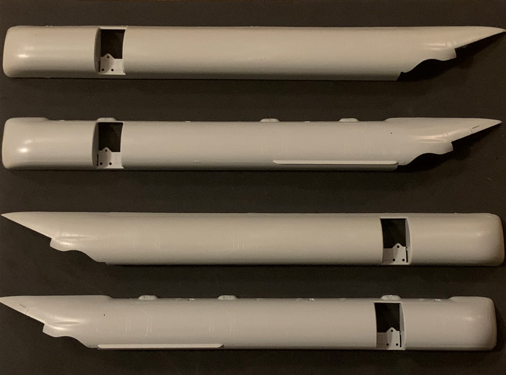
You’ll need to use the sponsons from the D model. They are the second and fourth sponsons in the photo below, with the strakes underneath, with but they will need the bumps along the top removed and the resultant gaps filled in.
Use the D model landing gear and rotors. However, there are examples of C models with the older A model rotors, so research the particular one you want to build.
Then you’ll need to remove these:
Ah, one more thing I forgot to mention in my earlier post - you need to add strakes underneath the ramp. The D model kit should come with them but does not. An easy scratch though.
Other than other surgeries that I plan to make that are not model specific, that’s a fairly complete list of what need to be done.
Looks great.
I saw this today on AndyHHQ, RED FOX STUDIOS has come out with 3D decals for the A and D model. 7 min mark.
")
Might be helpful for your build.
Thanks for taking the time to post that. Indeed they might be useful in the future. What I did not mention is that the particular chopper I’m modeling is destroyed, and has been robbed of a lot of its parts, including instrumentation.
I might even have fun with the center console:
That looks like really nice stuff there. My only concern is PDP faces are still designed for the inaccurate Trumpeter pieces. I’m going to fab them up based off of my measurements, and since I’ll need at least three sets I may make molds of them. I’ll probably have to settle for ridiculously thin strips of white decal film for the panel faces.
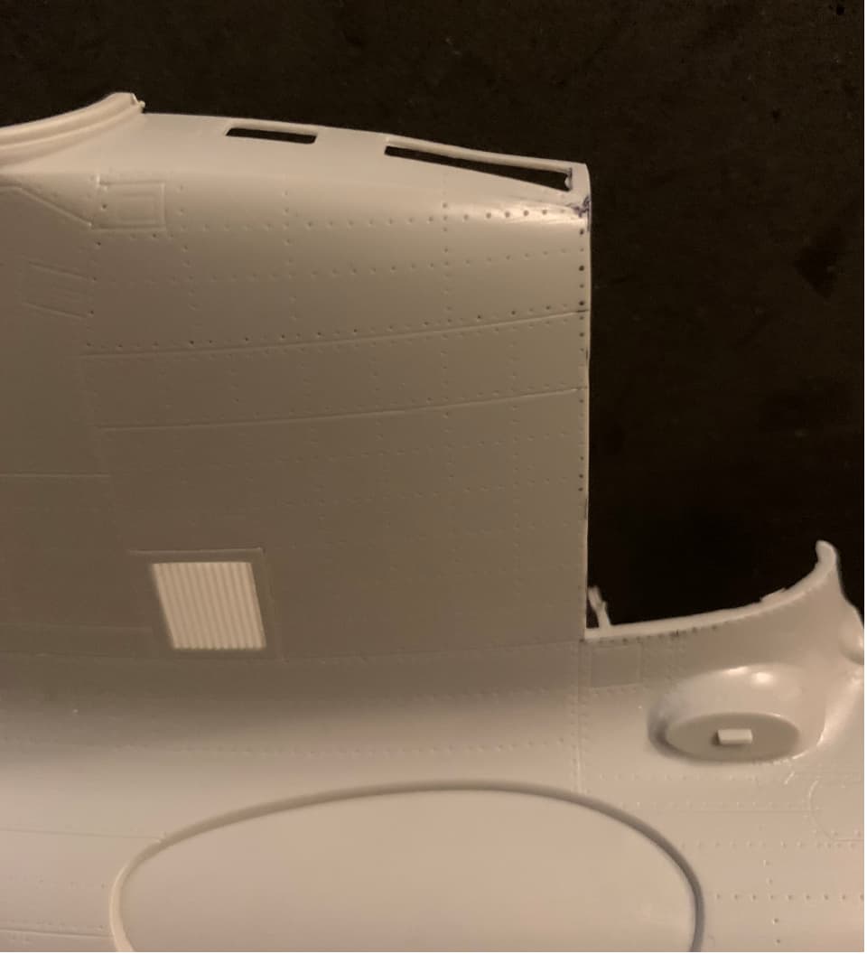
In the meantime, I did a bit of surgery tonight. I’m pleased with how the scribed panel lines came out. I tiny bit of liquid cement will even them out nicely. The louvers look the part as well.
I should probably point out that the louver arrangement provided in both kits is correct for neither. What I’ve done below will be necessary for the A model as well.
Looks like you are off to a good start. This should turn out very nicely.
I figured you would get to it. I did mention Trumpeter shows it incorrectly built, I just didn’t go into the details of how. I was simply pointing out another area that needs attention and offering up “a way” to address it, not “the only way” it has to be done. I mainly was interested in how hard it would be to articulate it; which it wasn’t hard to do if someone wants to tackle it.
A little more surgery tonight. The offending pieces were removed. (again, “offending” being a subjective term. No rocket scientry involved, just a little time. By the way, a good way to get the correct spacing if you do want to replace the framework is check out the vertical panel lines on the outside of the skin, which are correct for the most part.
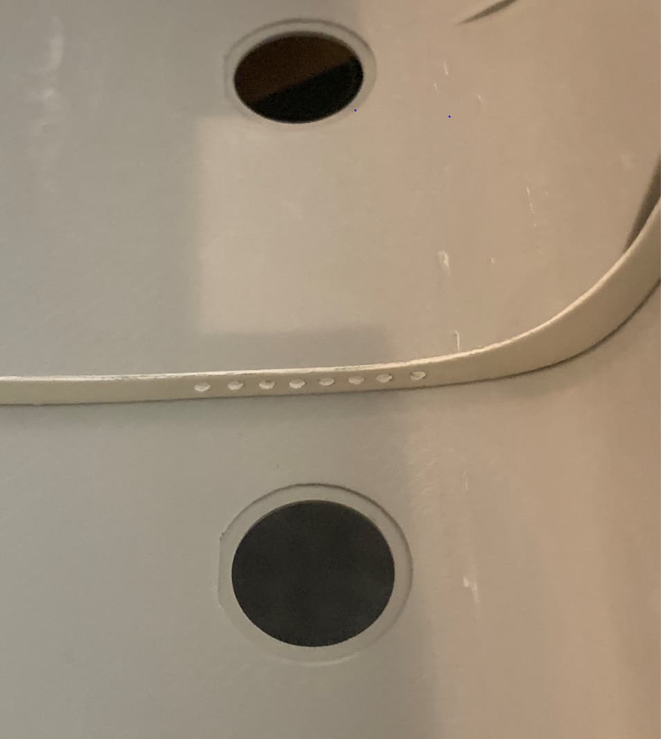
I figured the external lines were accurate so I have gone a crazy step further than you. SInce the ACH-47 has no padding inside, I sanded all that off to add the spars and stringers (that I don’t have). In order to place them somewhat accurately, I have started to drill out all the rivets from the outside of the skin. The intent is to then insert styrene rod through all the wholes and that would let me know where the stringers and spars go on the inside. Plus, as the rivets are mostly proud on the outside of the skin, I can shave the rods down and give that look as well.
That is closeted right now. It is waiting for me to find the interior stringers set from Cobra Company. Lone Star Models has the molds for this set, but hasn’t had the time to produce them yet. I am waiting, I have plenty of other stuff to work on.
I will try and follow what you do, as you are helping me with small stuff like the louvers and things. Keep up the awesome work. I am learning as you go!
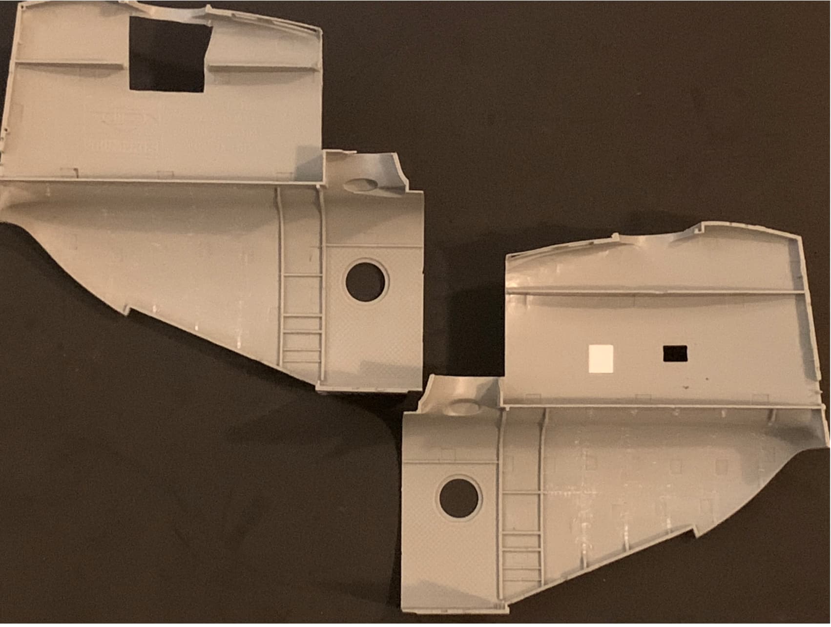
I mentioned I’d have to sand the padding off or cover it, so I decided to sand it off as well. You can see where I started on the left fuselage piece right under the porthole, but I just didn’t have the right grit handy. (I could move about eight motorcycles out of my way in the garage to access my stuff but I think I’ll just go to O’Reilly’s tomorrow.)
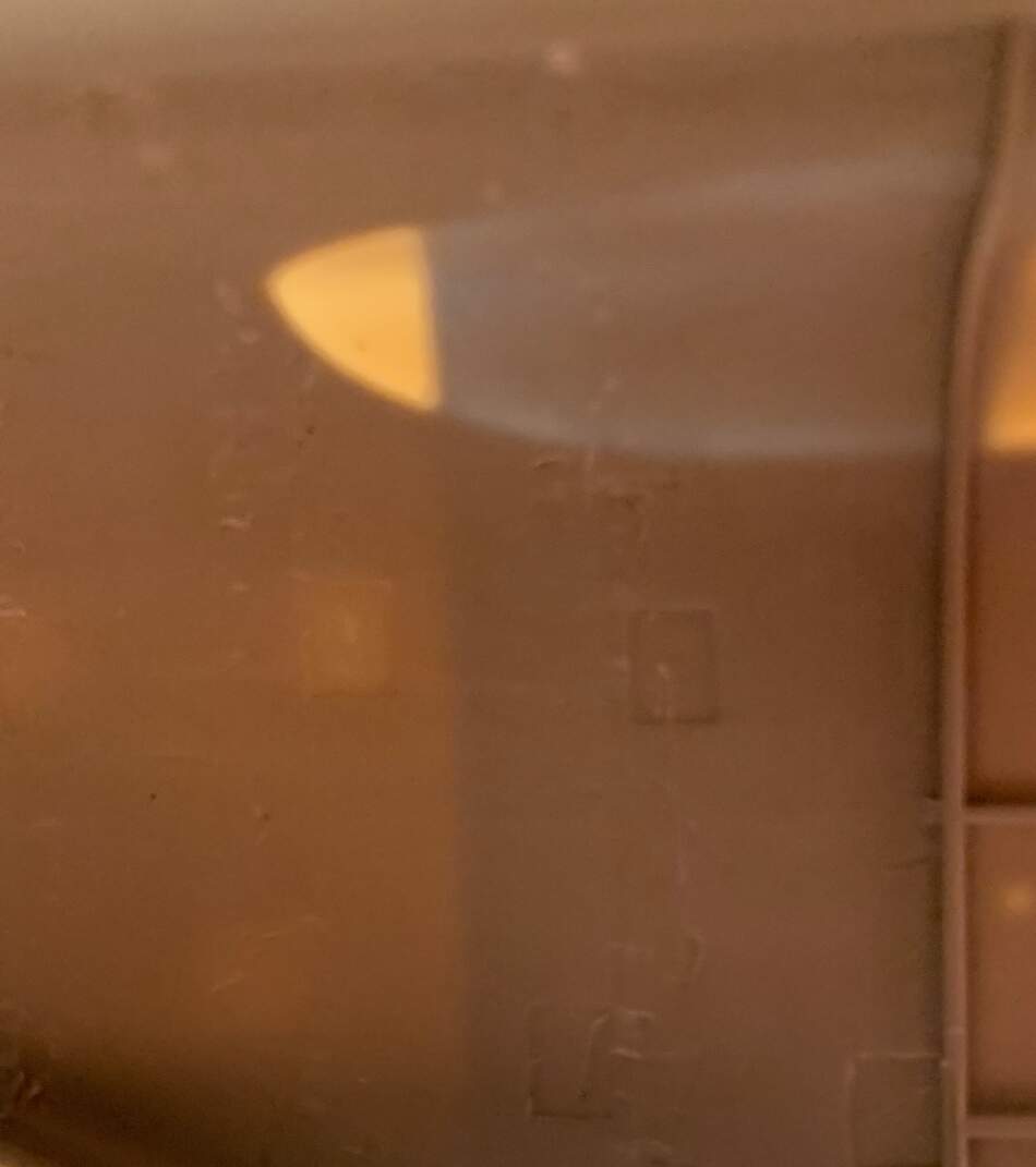
To mark the positions of the spars on the inside I simply place a piece of tape on the outside and shine a light on it. Then I mark the inside location with a fine point sharpie. Primitive, but effective:
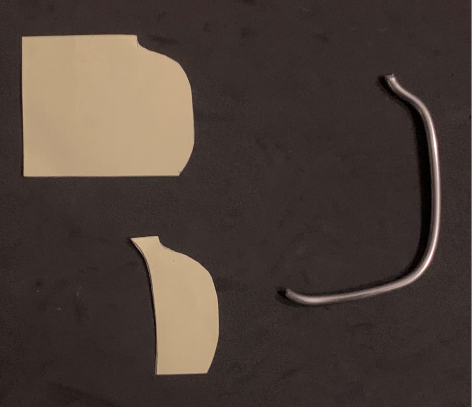
I can’t wait for that guy. I contacted him once about some firefighting equipment for a B-25 I was doing, and he seemed less than interested in pulling out his molds, so I did it myself. Which is what I’ll do here. Using my trusty contour guide:
I’ll stack styrene together and do several of the long fuselage pieces at one time. For the rear fuselage I’ll do the upper portions the same way, and then corresponding lower pieces of varying lengths.
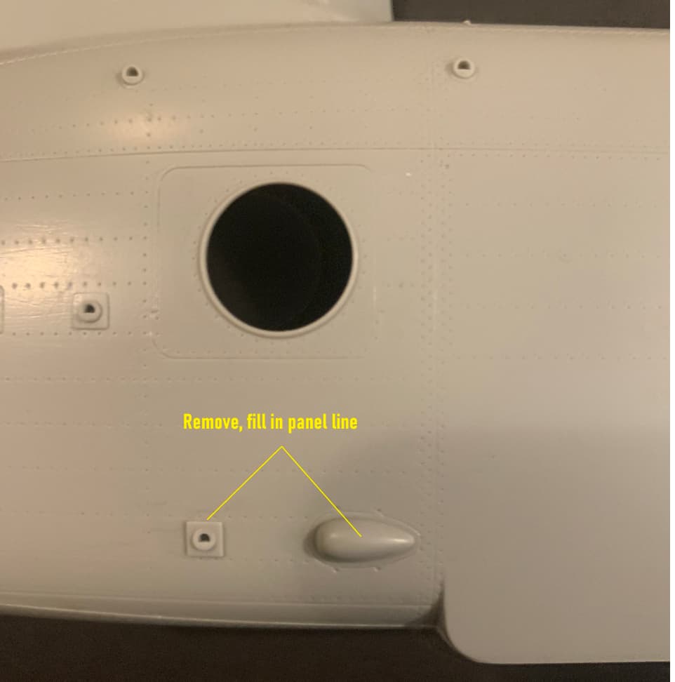
You are certainly more ambitious than I. I’m glad you mentioned the rivets, they should indeed be proud, but on the kit, although very finely done, they’re represented by tiny pinholes. All the more baffling because from a mold making standpoint the raised rivets would have been easier to do. This is quite vexing for another reason: I plan to remove several sections of the fuel sponsons on both sides. That will leave large blank areas that will need rivet detail. It’ll be inconsistent to have pinhole rivets on the whole aircraft and then raised rivets underneath where the sponsons were, yet I will do it just the same.
I plan to use these Archer rivets. The PE screws I purchased just for good measure in case I needed them for inside the cockpit.

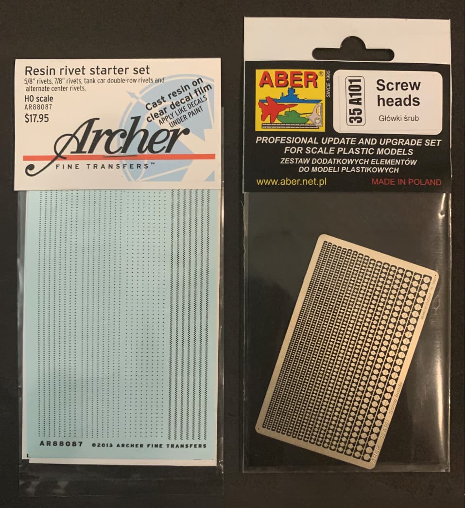
I used the Archer rivets on some Academy Black Hawk way back in the day for the framing around the windows, and the scratchbuilt framework I had to do around the doors. They work quite well but you definitely have to watch your paint thickness.
Oh my God, the pressure. All right, since you’re doing an A model I’ll scribe the panel on the opposite side for you. It’s a bit different. Where are you going to source the correct wheels?
Edit:
I found some 150 grit I use for sanding rust off of old motorcycle frames. It took the quilted texture off the interior parts most rikki tik. I guess I’ll call it a night.
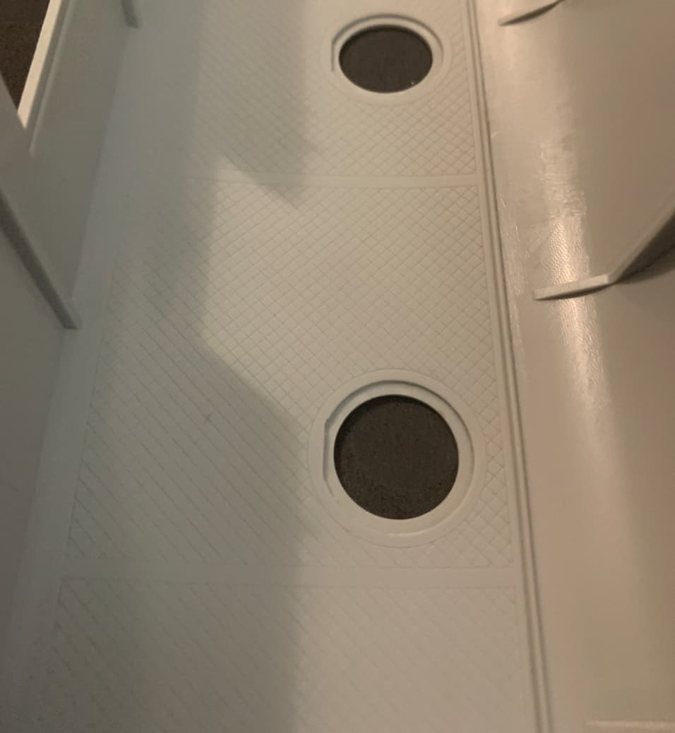
For any of you unfamiliar with this beast, this is the texture we’re both removing.
I hadn’t gotten as far as thinking of wheels yet. I have been more concerned with the interior. I have a contour guide as well and purchased it specifically to do this kits ribs and spars.
The previous posts were just for the C model conversion. The rest of the build is non model specific - can be used for A,C, or D models. Except for the forward rotor head mount which is very different between C and D models, and will be exposed.
A little cleaning up on some removed panels:

My homemade contour guide seems to be providing good results.
But making one piece is easy enough. Making several not so much…
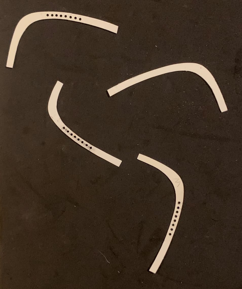
Each spar is slightly different and must be constructed separately, however, the eight holes between the large lateral stringers above and below each window are common to most of them.
Found the post! Nice work so far. I love how you (and the most of you) cut the panels and leave them so smooth. Something I never could make. So this is one of the reasons I don´t transform the kits.
how did I miss the start of this thread… gonna hold on from here on in.