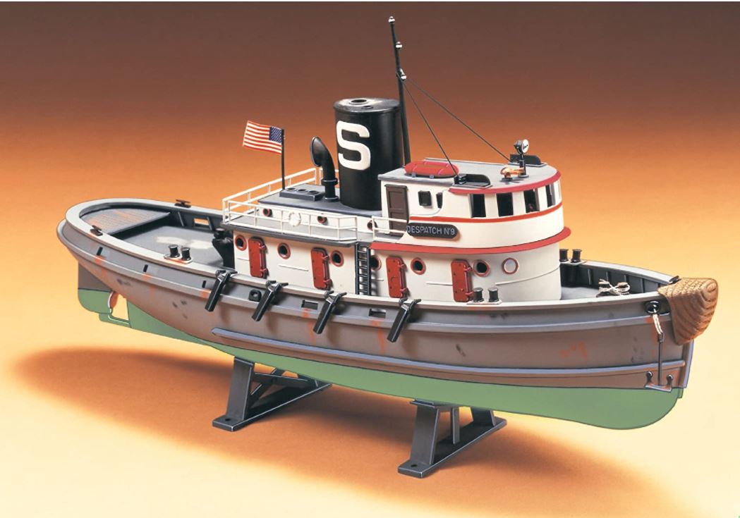
I want to convert the venerable Pyro/Lindberg 1/87 Diesel Tug into a rc 1/144 WW2 Assurance Class Admiralty Rescue Tug. They have deceptively similar hulls but one is a peewee and the other an armed ocean-going titan. It is odd how little the hull form was changed for a very different and demanding role.
The first issue was how to handle the hull break and raised foredeck. Looking at online builds it seemed like just a strake of plastic sheet atop the rail would do but thinking it over that seemed a pretty flimsy support for the entire superstructure. I was tempted to go simple and glue the foredeck atop the rail and skip the hull break but that is a big feature to just skip. Then yesterday it occurred to me; just glue a sheet of balsa atop the rail; the thickness of the break. It can have a large opening for hull access then a styrene sheet deck on top held on by magnets or whatever. That will have the right shape, be strong and more seaworthy than the kit as designed. As a bonus, the front end can overlap the rail and get contoured with putty underneath to better capture the sliight flare at the top of the bows.
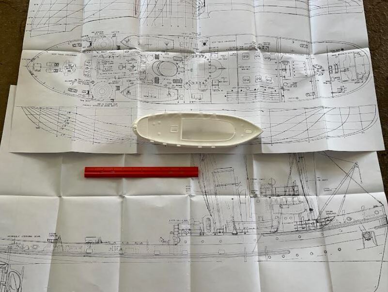
After fussing over all the photos online I splurged and ordered the 1/48 plans online to take the guesswork out of dimensions. To offset the cost this time I might scratch-build the weaponry.
Now to figure out the best glue for styrene to balsa that won’t have bits breaking off every other minute.
I have been thinking about how to get access to the interior of smaller RC-ships.
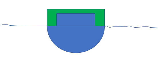
My plan is to cut the hull at the waterline. Make a deck to cover the lower hull, two large hatches in this deck with lids that can be made watertight or a raised coaming that goes up, or nearly up, to the weather deck.
The upper hull would then fit like an upside down box on top of the coaming.
This allows the weather deck/decks to be free from openings and provides better access to the
tech inside. Small/Delicate topside details are not endangered by the opening and closing of hatches.
Primitive sketch, blue is lower hull with raised coaming around hatch, green is the upper hull.
The upper hull more or less turns into a static waterline model.
The requirement on the seal, if it is at the top of the coaming, is actually the same (or even simpler) than having a hatch in the deck a few 16ths of an inch higher up. If the fit between the hatch coaming
and the upper hull is reasonably tight (we DO NOT want a press fit, see previous post about delicate details) the seal on that large hatch could be a simple lid.
Instead of an exposed hatch in the weather deck there would be a similar hatch covered by a big lid.
I think water splashing over the weather deck is a greater risk than water that would need to penetrate between the waterline deck, up around the hatch coaming and then work its way into the hatch.
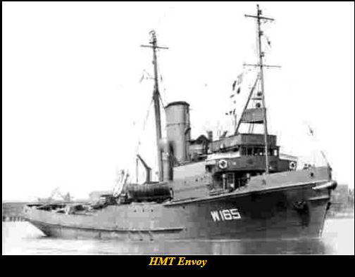
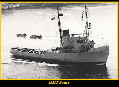
and Assurance Class tugs(narrower deckhouse with overhanging bridge wings)
BOTH seem to share the same hull. They also often jumble names and classes. But all I’ve seen share the same vertical strake the height of the hull break and running forward to the bow with a slight overhang at the front creating a flared bow… So does the set of plans I ordered. That’s what inspired adding a balsa layer to create that strake.
Just one catch:
EVERY photo I’ve found of the actual ships of both classes show a smooth curve right up to the deck with no vertical strake as in the models.
It’s conceivable different yards made the hulls slightly differently, but then WHY can’t I find a photo matching the model design? Could it just be a quirk of the Slipway model design that has gotten propagated all across the model world. I have to decide whether to follow the models example or the ship photos.
The Assurance class were not run of the mill utility tugs. The Royal Navy built them and several other classes to accompany convoys right across the Atlantic and Arctic oceans working in all weathers under fire to take u-boat or bomb damaged ships under tow and bring them safely to harbor. Ultimately they and their sisters saved three million tons of merchant shipping and 254 British and Allied warships as well as thousands of lives. Five Assurance class tugs were lost in action as well as 15 others of various classes.
Interesting project, I built a small Saint 1/72 tug many years ago and it ran well, only the superstructure and engine room skylight were removable. I brought the tiller head above the deck and hid it under the grating in the stern. Access, I built an Insect class gunboat many years ago where all controls and power were in a pod that dropped out of the bottom of the hull, worked well. I did put a clear Perspex cover over the pod but it was never needed
Blowing up the online sketch to full size, I see I need to raise the forward rail 1/4", so a sheet of balsa (or 2 plies one on the other which would help rigidity) would do the job.
The top of the Wheelhouse would be about 1/4" below the kit wheelhouse and MUCH shorter. But the weight of the taller funnel and the masts adds to that, so I should think about cutting weight down anywhere possible.
I might also attach the ballast under the keel, increasing its moment arm and preserving the buoyancy of the inside volume the ballast would otherwise take up. That might be inauthentic, but would help stability.
I’d cut a hatchway under the engine room skylight, put a bulkhead near the back of the foredeck and cut away nearly all the original foredeck to lose even more deadweight. Then make the masts a bit thinner than scale and wood for lightness. The rear deck would be so close to the water it would need to be watertight with good scuppers to clear any water that comes aboard. The raised foredeck raises the moment arm but if sealed would mean several square inches of reserve buoyancy in case of trouble.
Come to think of it, I could put the same coaming around the existing deck opening as I’d use for the stock kit, then fill the area around it with balsa, making flooding impossible. (wheels churning furiously inside head)
Real tugs ALWAYS have watertight doors up to the pilothouse level, and proper practice is to keep them sealed tight whenever towing. If the tug veers from wind wave or current and the towline moves abeam it can pull the rail underwater in a trice; a phenomena known as “tripping”. I recall a show about a British tug towing a big ship to an upriver port recently with the doors open. It tripped and sank like a rock, drowning everyone below decks.
I don’t build ships, but I find them absolutely fascinating (Drachinifel is my jam) and this build has piqued my interest even more than normal. Really excited to see her take to the water Danie.
Have you measured the available displacement?
Fill a suitable container/bowl with water up to the rim, add some detergent to kill the surface tension, put the hull in the water and add weight to it so that it floats at the desired waterline.
Put the weighted hull on the scales.
Now start adding up the RC equipment and batteries and deduct it from the available displacement to get the styrene budget.
I would avoid balsa and go for thin styrene sheets instead.
When you finally get a smooth, solid and watertight surface on the balsa it will weigh just as much, or even more, than thin styrene sheets.
I did better! I’ve already built the kit as an RC model years ago and had great fun with it. All I need to do is keep the new build within the parameters of the old one. I loose the heavy deckhouse for a smaller lighter one of card but have the raised deck and tall masts added to the mix. I’m pretty confident.
One thing half an inch of balsa over the deck will do is give a tremendous righting moment whenever it tries to tip. Given the light weight, it’s worth it.
The plans arrived and turned out to be just the same two drawings blown up large, along with some generic advice on hull-building. Not even good 3-views of the deckhouses. AND it confuses the Assurance and Envoy classes. And it’s left to the builder to figure out details like access hatches.
At the scale I’m working in just looking at online builds will give more information.
I’ve glued up the balsa upper deck, traced its outline from the existing rail of the model, then drew in the overhang using my trusty French Curve from my freshman Engineering Graphics drawing set.
Next I roughed it out with a razor saw and it’s time to carefully sand it to its final shape.
This site gives a good idea of the Deckhouse geometry, I just need to reproduce it in styrene sheet from the drawings and measuring from the model itself. https://www.loyalhannadockyard.com/MSASSURANCE.htm
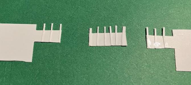
No huge progress this weekend, just little time-consuming steps: Cutting and smoothing the prop shaft housing and bushings ready for soldering, carving away the front end of the deck-edge wale to match the Assurance hull, and laying out the form around which the lower deckhouse will be built.
Also receiving and testing the transmitter, receiver and the continuous-motion servo for the motor and puzzling over whether and how to try to change it’s gear ratio. If I give up on that, it will be time to remove the gear train and cut the shroud around the drive pinion away to ready it for its new role as motor. But I’ll wait to do that until I’m sure.
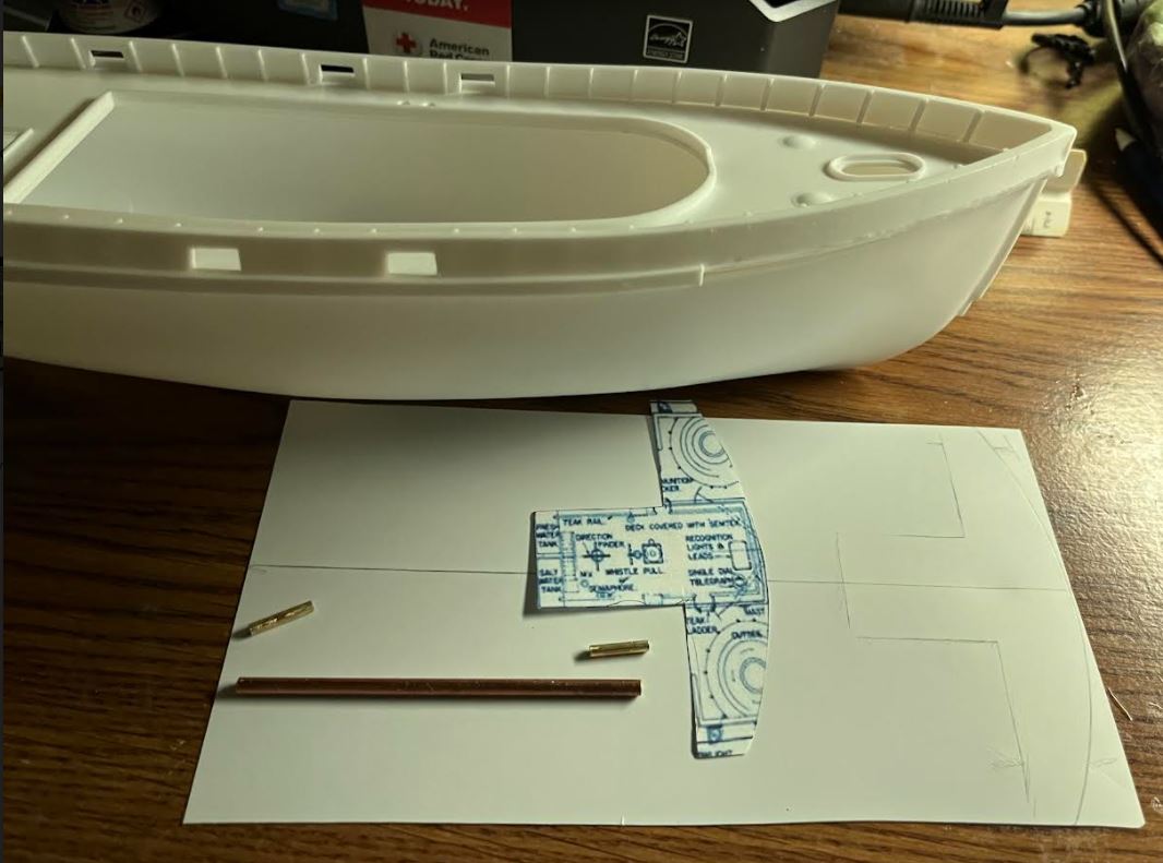
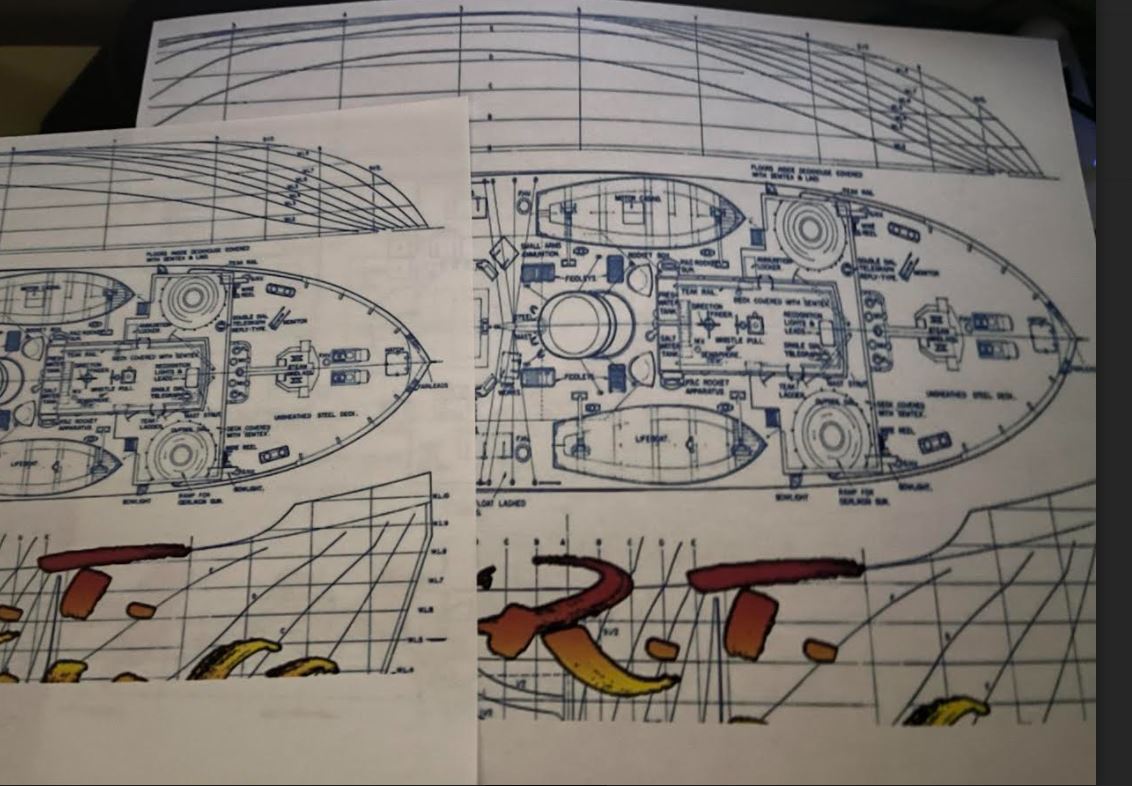
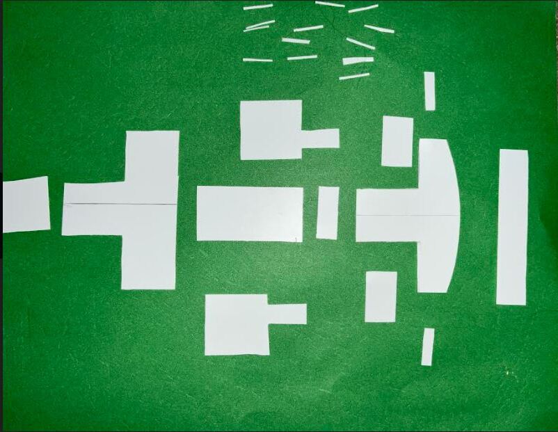
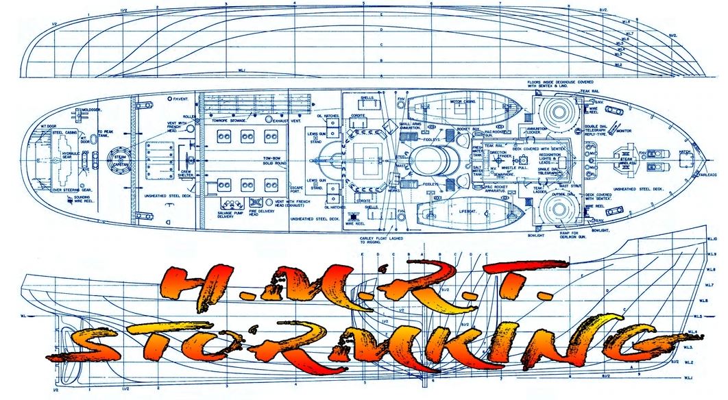
The Assurance Class turns out to be just a bit narrower than the Lindberg hull, so I calculated the ratio, loaded the image of the deck plan into Paint, widened it by that ratio and printed it, making several copies to allow cutting some up into templates to help cutting out components from styrene sheet.
Without grabbing a measuring scale, the inaccuracy won’t be that obvious when churning busily through the water and after all, this IS a kit-bash.
Oops, I used a too-small scale reject in the photo; the actual difference isn’t as bad as it looks. It took a lot of trial and error the get the hard copies exactly the same size as the hull. I should throw away all the rejects before I ise one for dimensioning and get a wrong-size part!
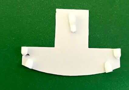
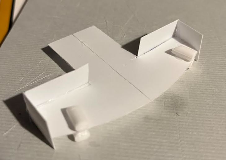
This piece sits at md-lower deck level to serve as a form around which the deckhouse pieces will fit. Bits of sprue are glued on to raise it to the right level and more than just the edge for the pieces to glue to, providing more strength.


 I have to decide whether to follow the models example or the ship photos.
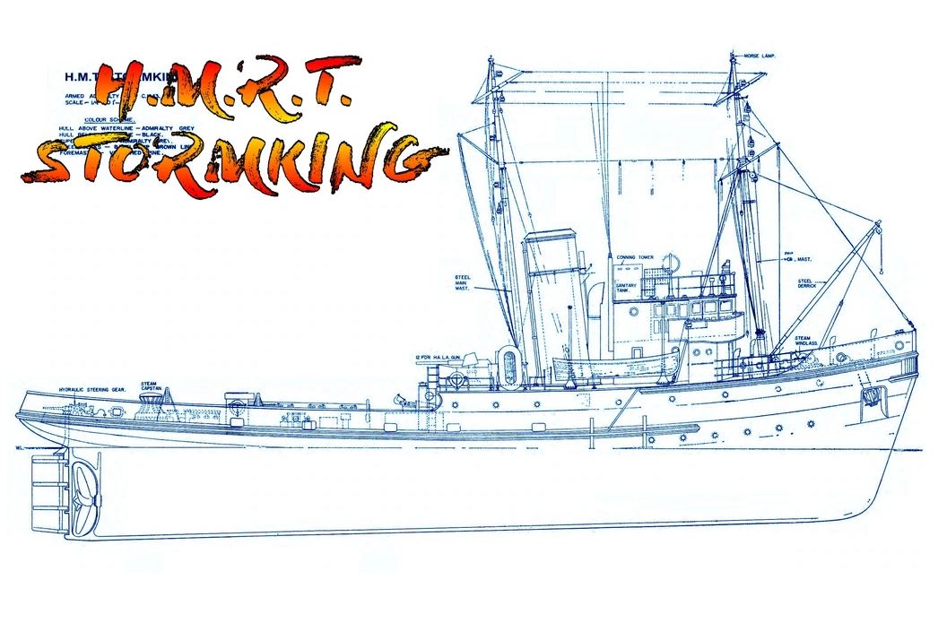
 Given the light weight, it’s worth it.