WNW Sopwith Camel USAS

So… I haven’t built a fully rigged biplane model since I was about 9 or 10 years old when I built the old Monogram Wright Flyer. Molded in color, IIRC, the rigging was done by lacing black sewing thread through the molded on rigging holes in the struts and wings. Well, that was back around 1970, so it’s been a while, to say the least.

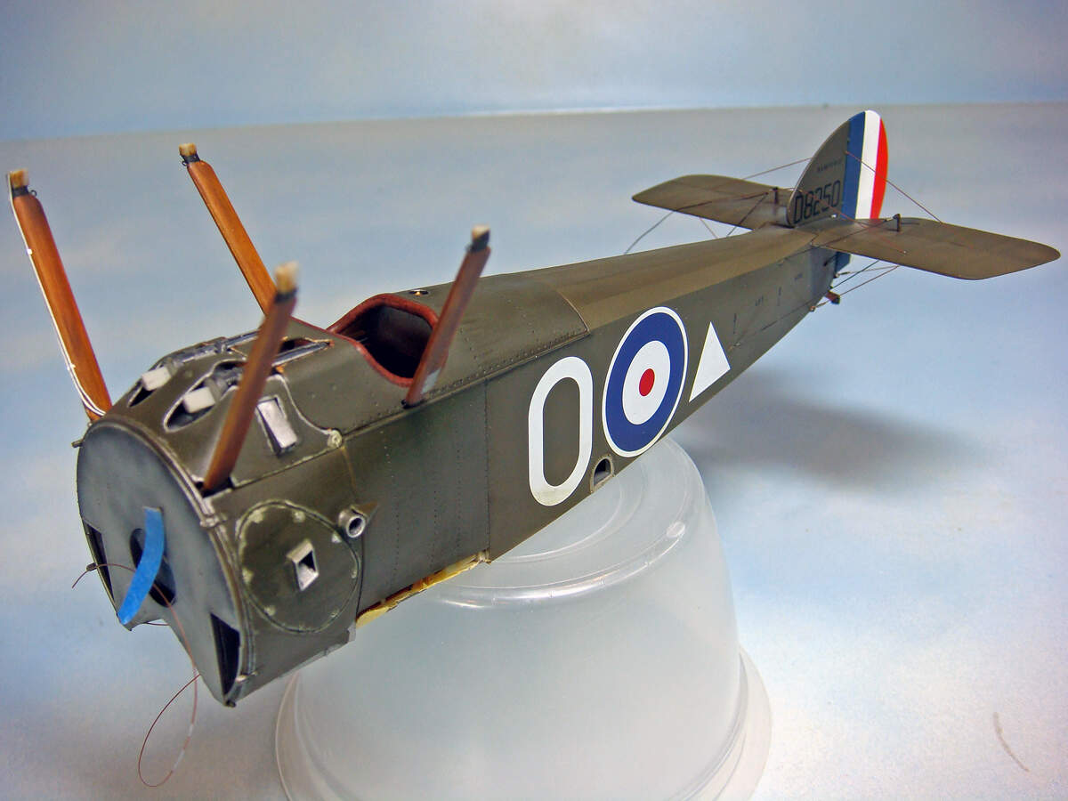
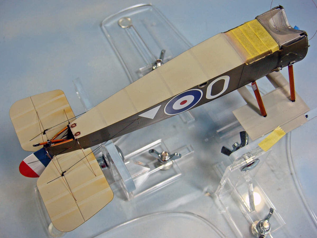
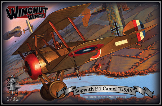
I generally build armor, but occasionally I’ll do something else, either for the challenge, to learn some new skills or techniques or just because the subject is one that I’ve developed an interest in. In the case of this project, the WNW Sopwith Camel USAS, it’s a bit of all of the above.

boxart

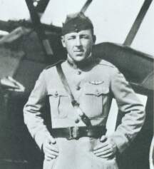
I’ve got a mate in our local IPMS chapter who grew up in the upstate of South Carolina. Among his stories are some about a gent, Elliot White Springs, and his family. Not to stray too far from the topic of modeling, it’s enough to say that E.W. Springs was a WWI ace who started the war flying with the British in the SE5 and later transferred to the US Air Service where he flew in the Camel F.1. He was credited with about 17 kills (the exact number depends on the official source and how the kills were counted differently by the British and Americans).

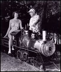
After the war, he went on to author a number of novels on WWI and early aviation, and he was quite well known for this back in the interwar years. Later on, E.W. Springs took over his family’s textile firm, and for a long time in the '40s, '50s and '60s, he and his company were even more well known for their risque (for the times) advertising campaign that featured the “Spring Maid” girls (a play on their original slogan, “Spring Made”). Buxom, short skirts, very cheese cake, the “Spring Maids” were what every housewife wanted to be if she made up her beds using the sheets and pillow cases from the Springs textile mills.

springs


imagesJFL7SXSB

Anyways, with a resume like that, how could I resist the home team ace and entrepreneur, E.W. Springs’ Sopwith Camel F.1?

I’m no experienced WWI aircraft modeler, so I’ll avoid any attempt at adding to the many good reviews of the Wing Nut Wings kit. A simple 5 minute search online will turn up plenty of information about this kit and all of their other offerings. It really is too bad, though, that WNW has gone out of business. However, I suppose there’s hope that their kits will eventually be released. Clearly there’s demand and the kits are so well designed and engineered that they deserve to continue on.

At any rate, I started with the kit a few weeks ago. Unfortunately, since I’m no experienced aircraft modeler, I was too focused on trying to both learn some new techniques and materials while at the same time trying to figure out the best construction and finishing sequences. In sort, I was just to engaged with the work to stop and take any in-progress photos.

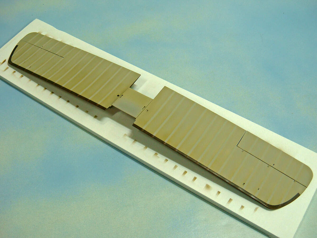
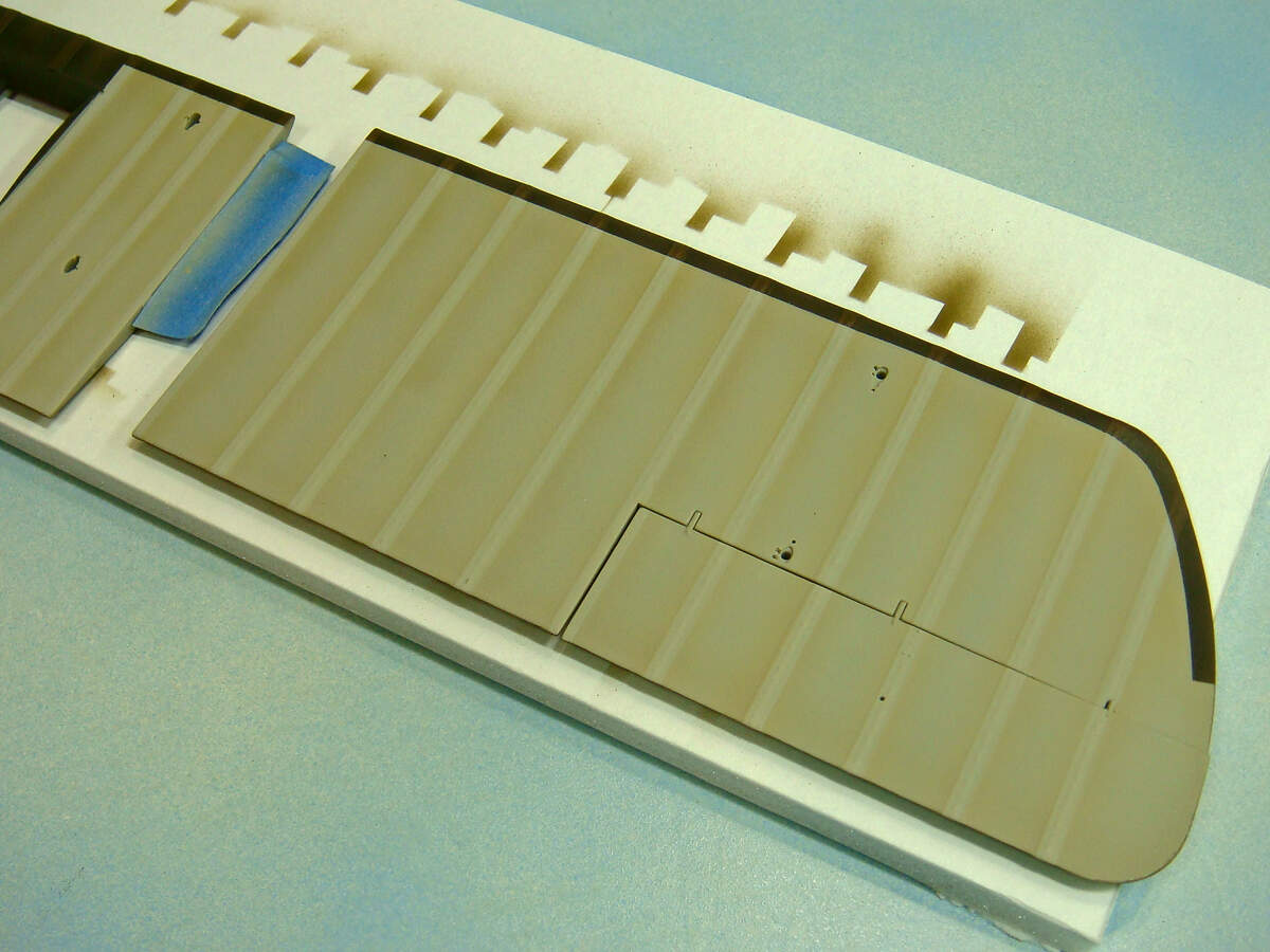
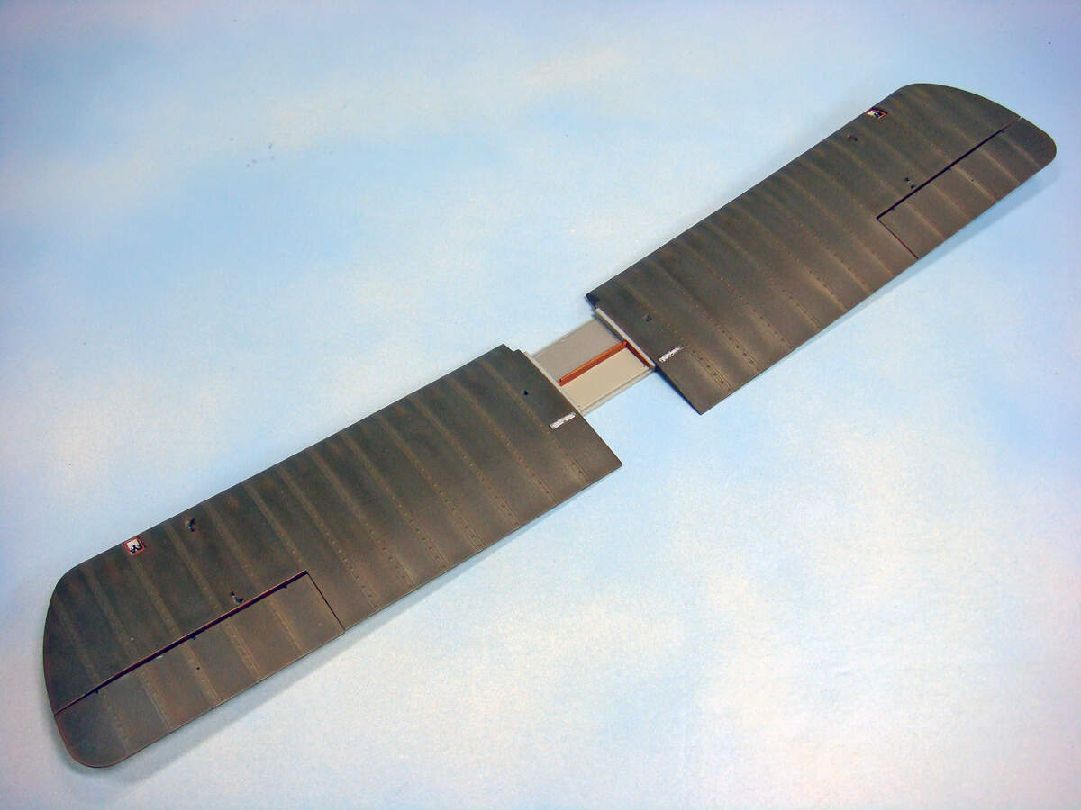
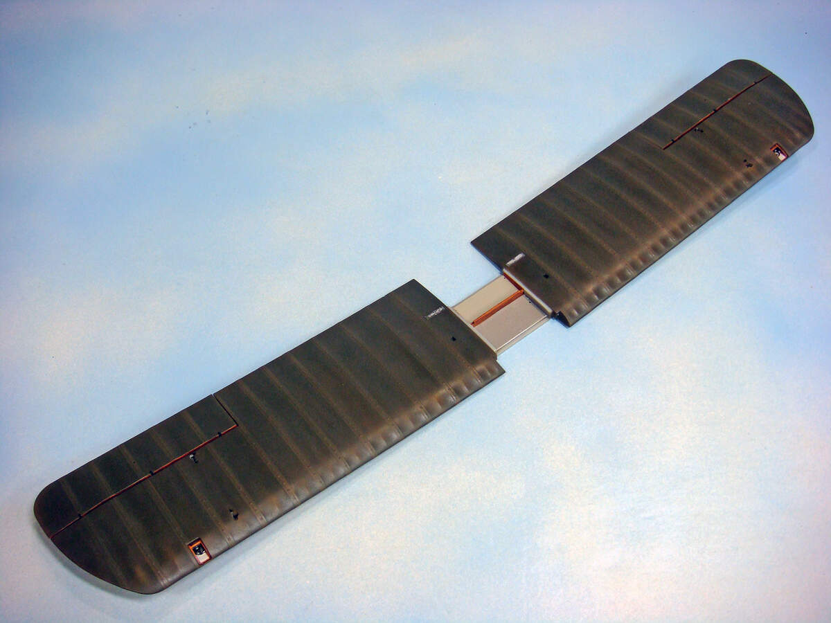
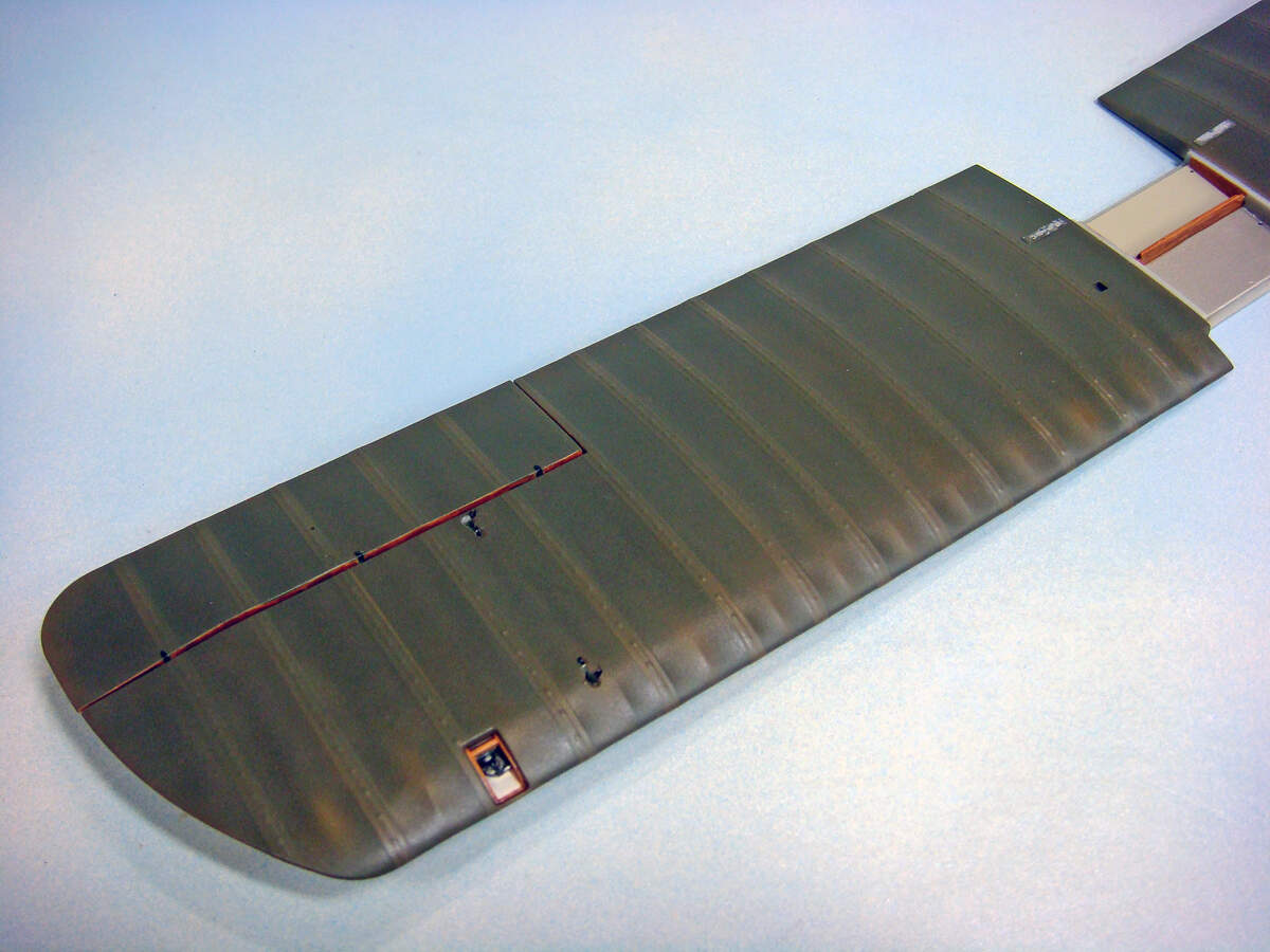
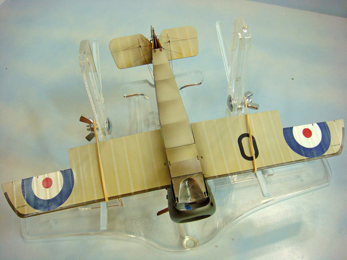
I did pretty much follow the sequence and build suggestions by the many WWI biplane modelers out there, so the work illustrated follows, I believe, the conventional approach used by others.

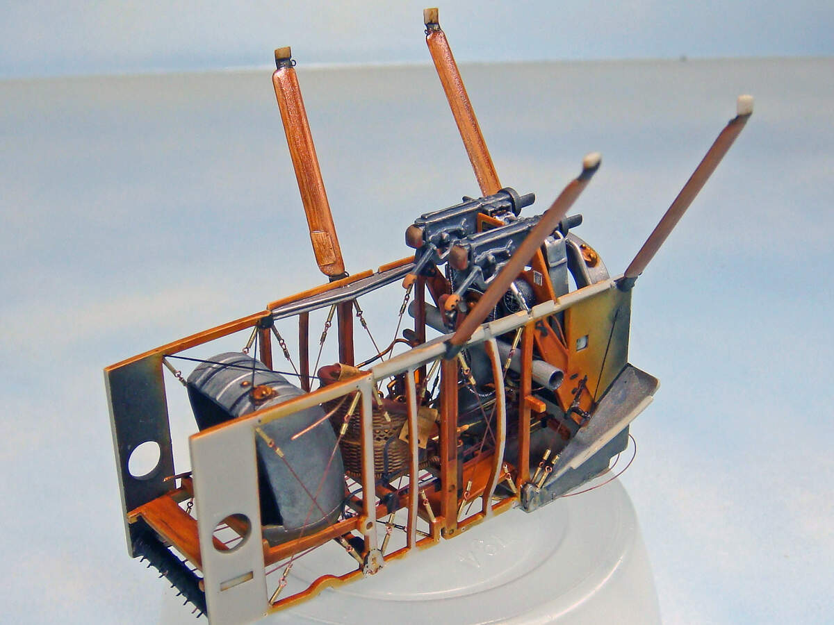
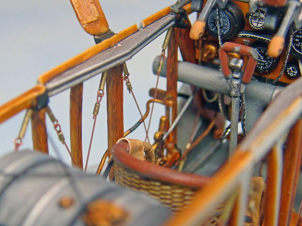
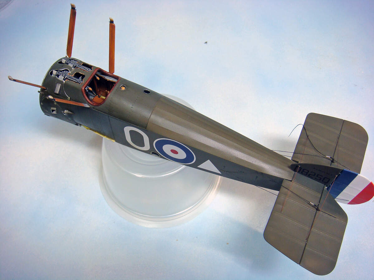
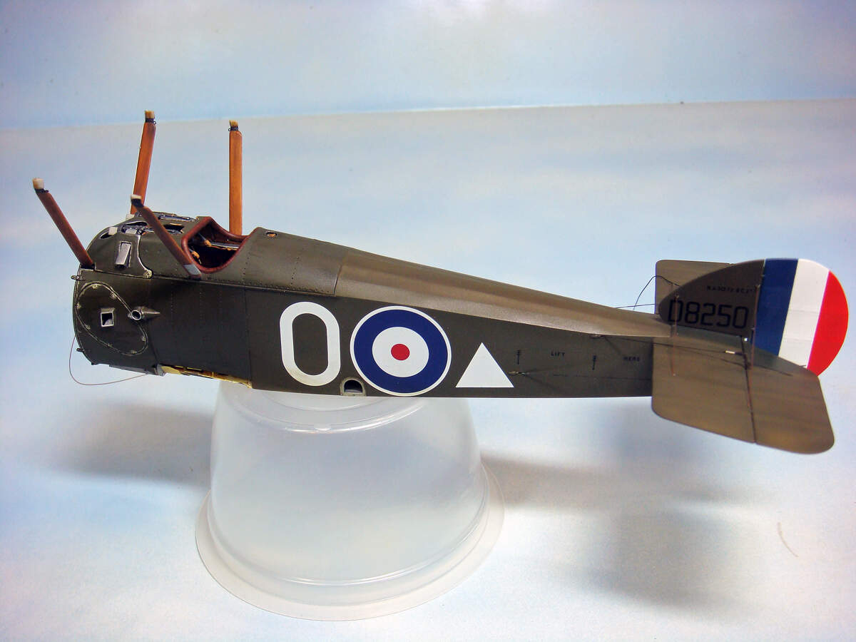
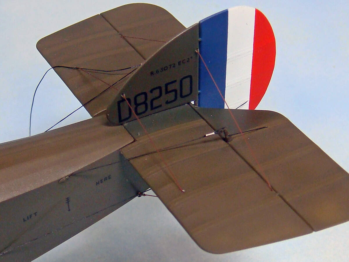
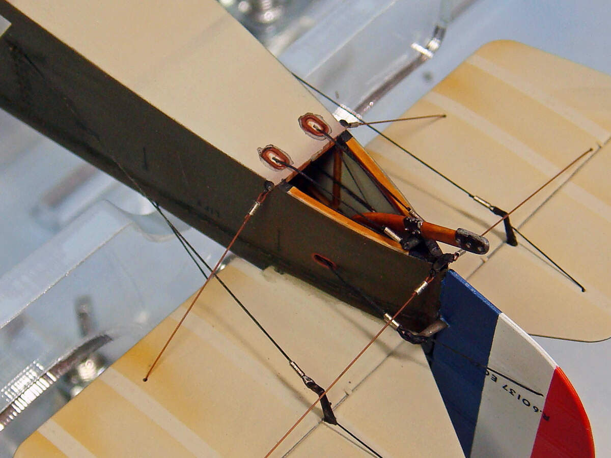
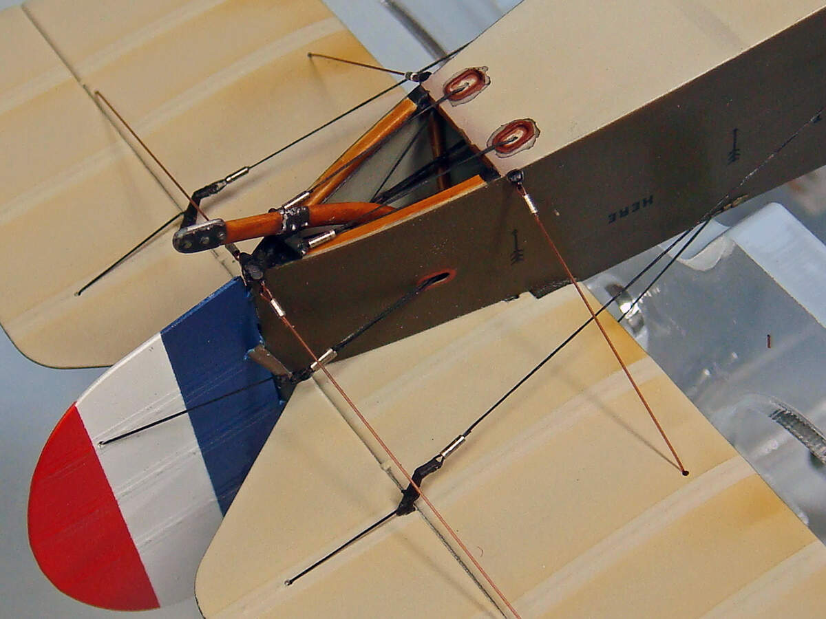
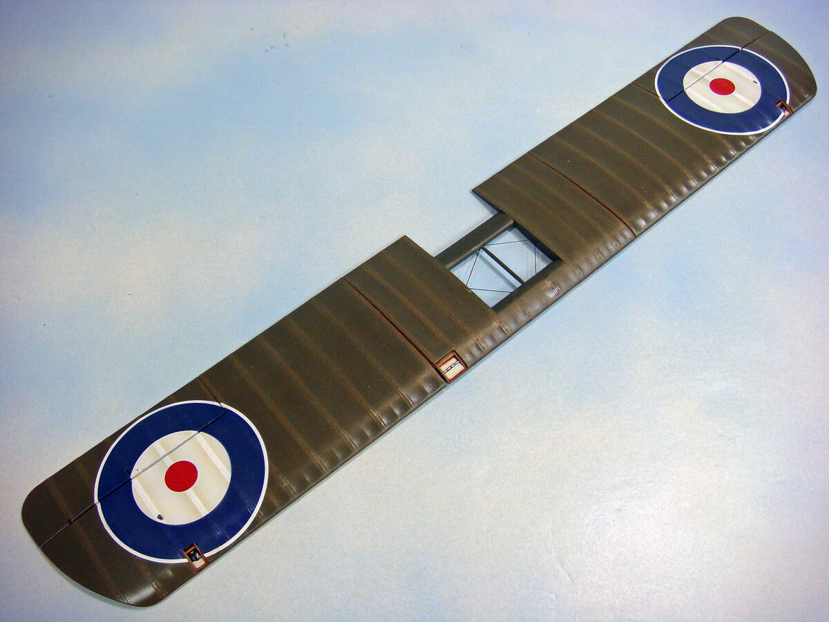
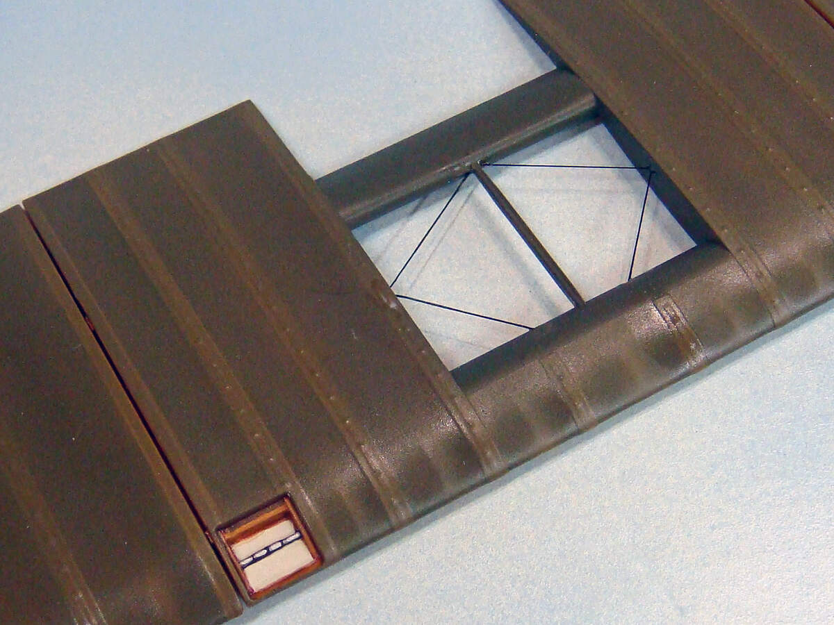
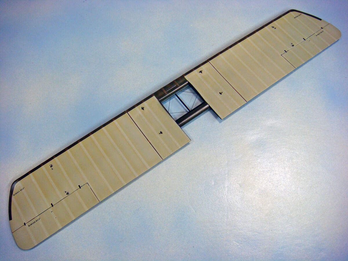
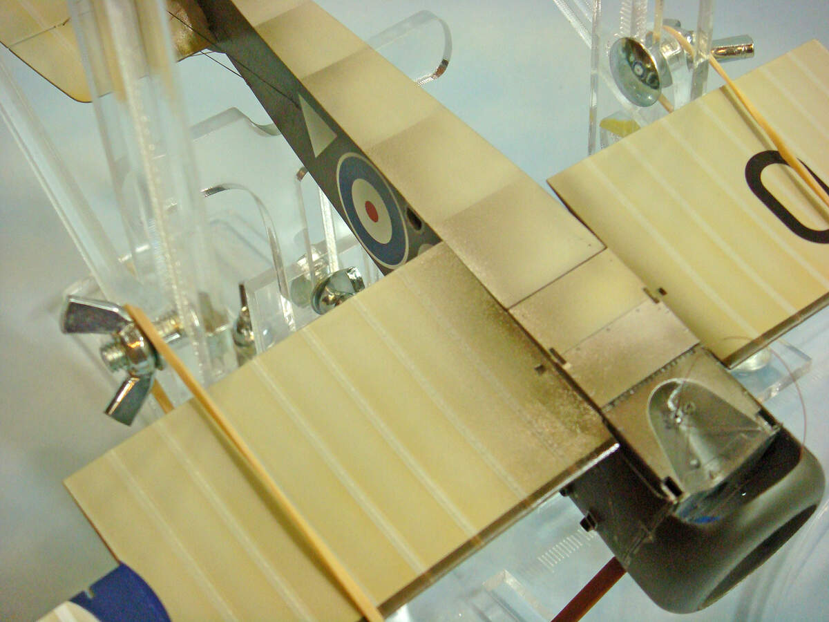
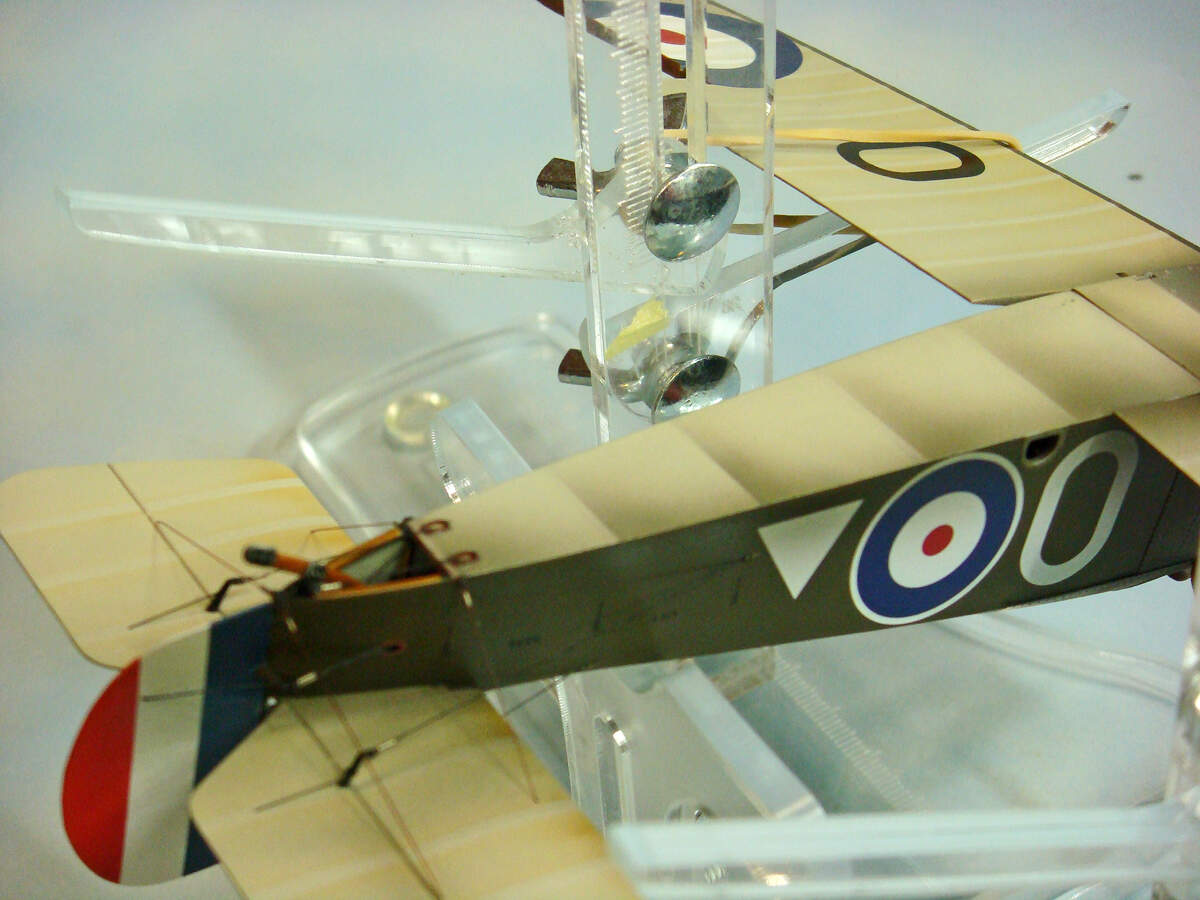
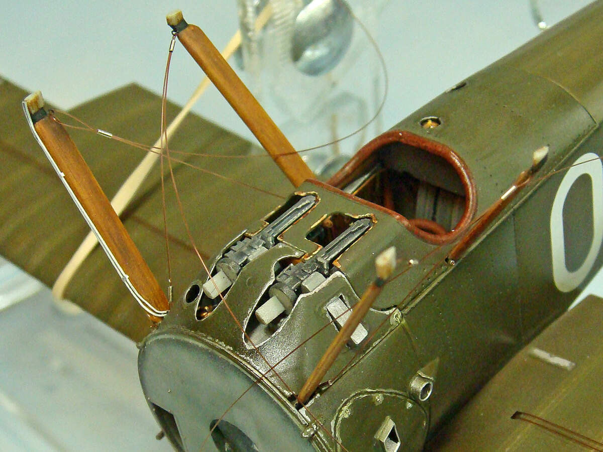
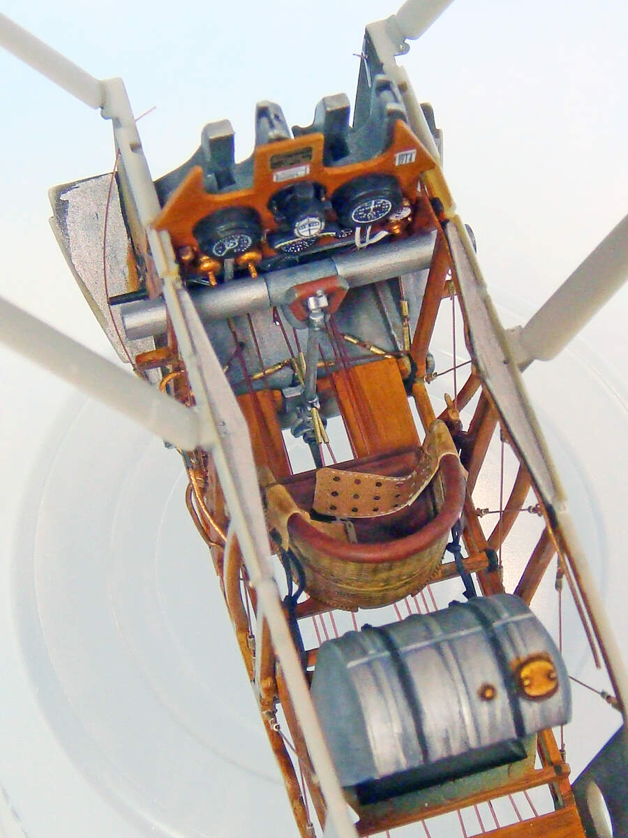
The bracing wires were done with 2# monofilament fishing line. The clevises were cut from .5 mm Albion brass tube. The eyelets were twisted from fine, approx 32 ga. copper wire.

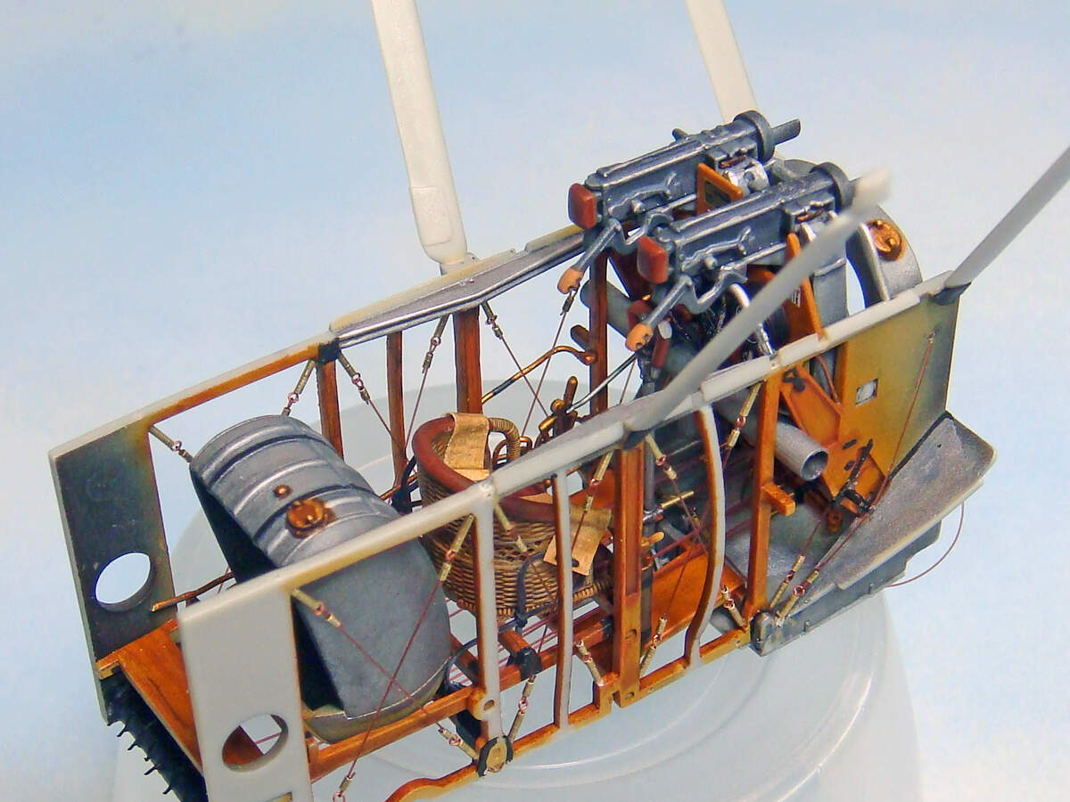
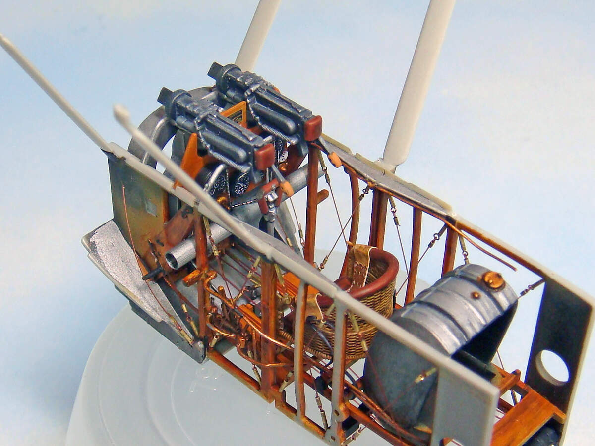
The control wires were made with 3# monofilament fishing line with .4mm Albion tubing for the ferrules. I think if I was to do this again, I’d use Easy Line or the 2# monofilament for these. Although the instructions show the control lines as thicker in diameter than the bracing wires, the visual difference isn’t enough and the thicker mono was much harder to tension and work with.

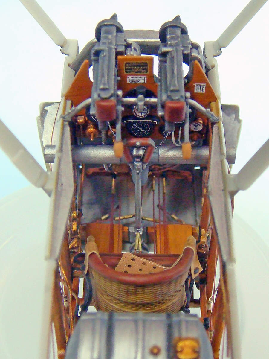
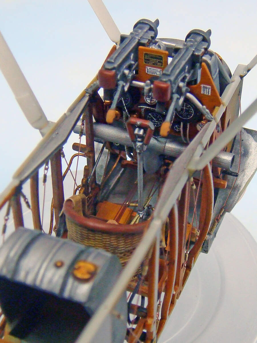
The seat belts are the HGW laser cut “fabric” belts. They’re really nice and easy to work with, but honestly, they don’t really look any better than the kit provided PE belts. So another lesson learned: Next time I’d just anneal, paint and use the PE belts.

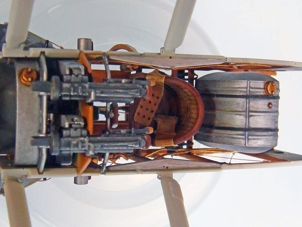
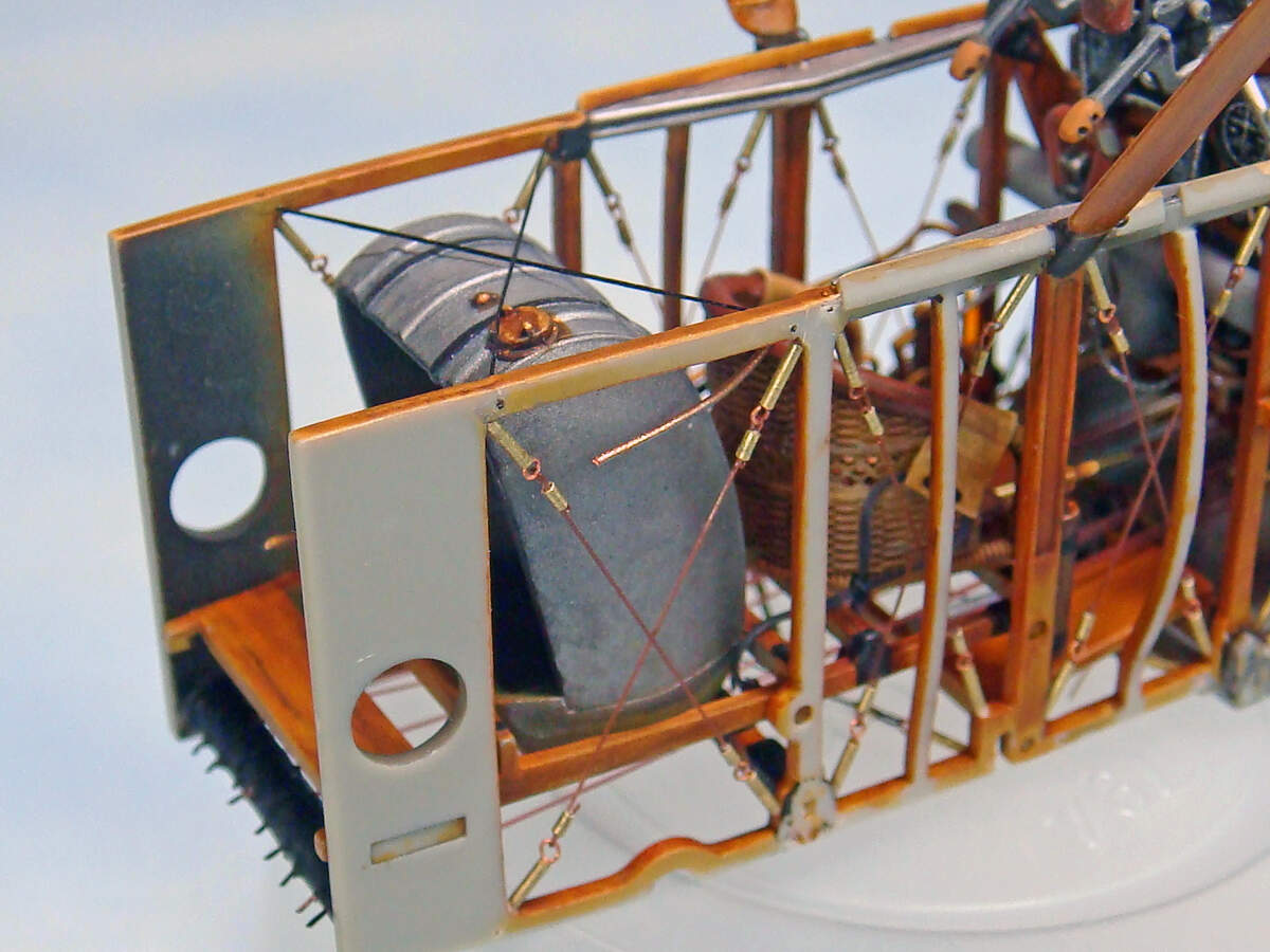
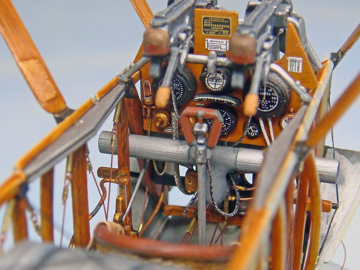
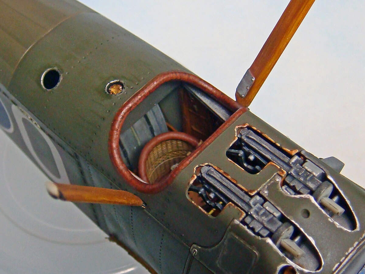
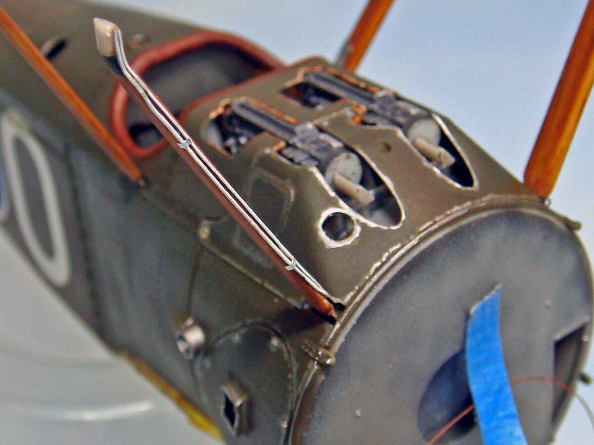
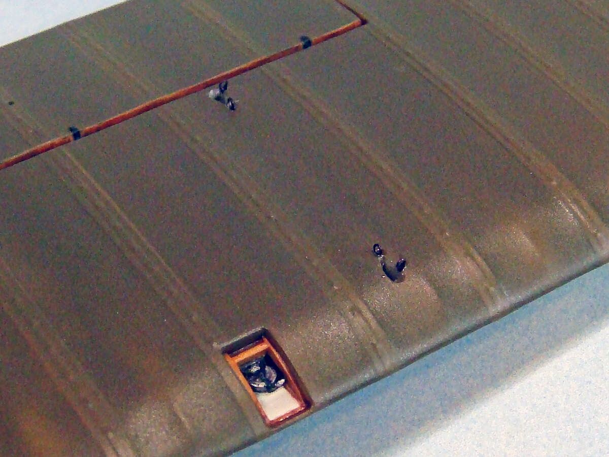
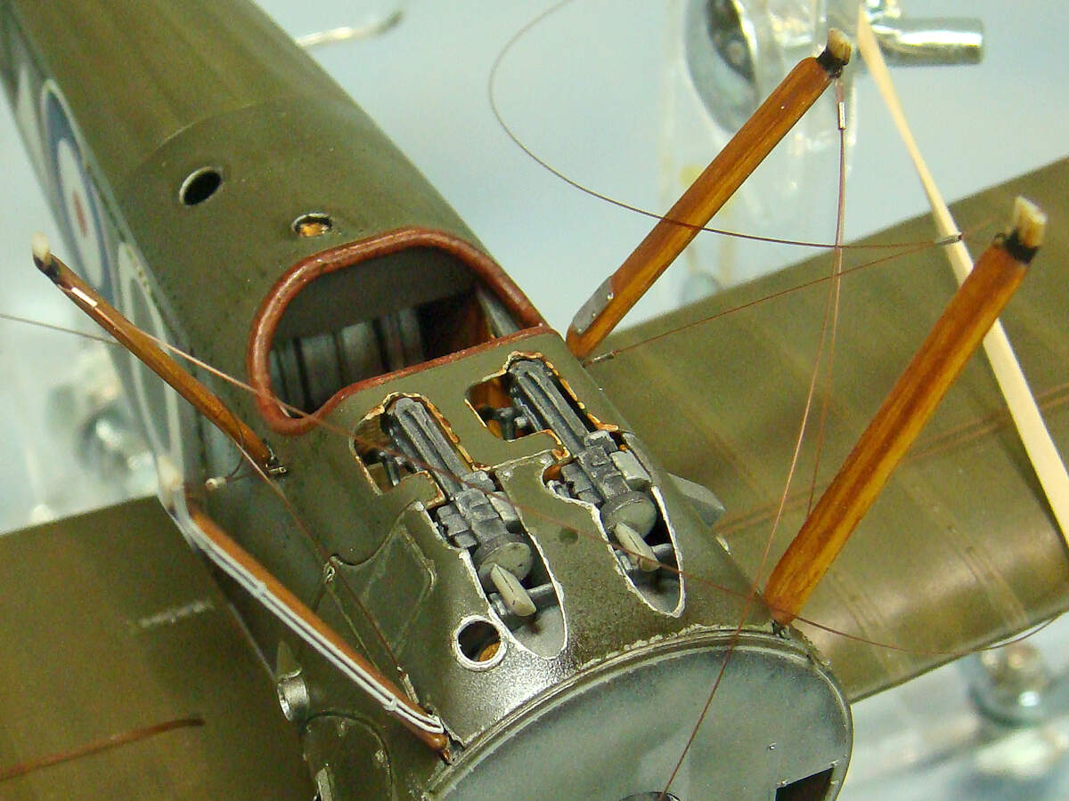
I removed the molded on fuel lines and replaced them with new lines made from lead wire. I also have a piece of clear stretched sprue for the glass fuel gage cylinder that I’ll add before I close all this up in the fuselage.

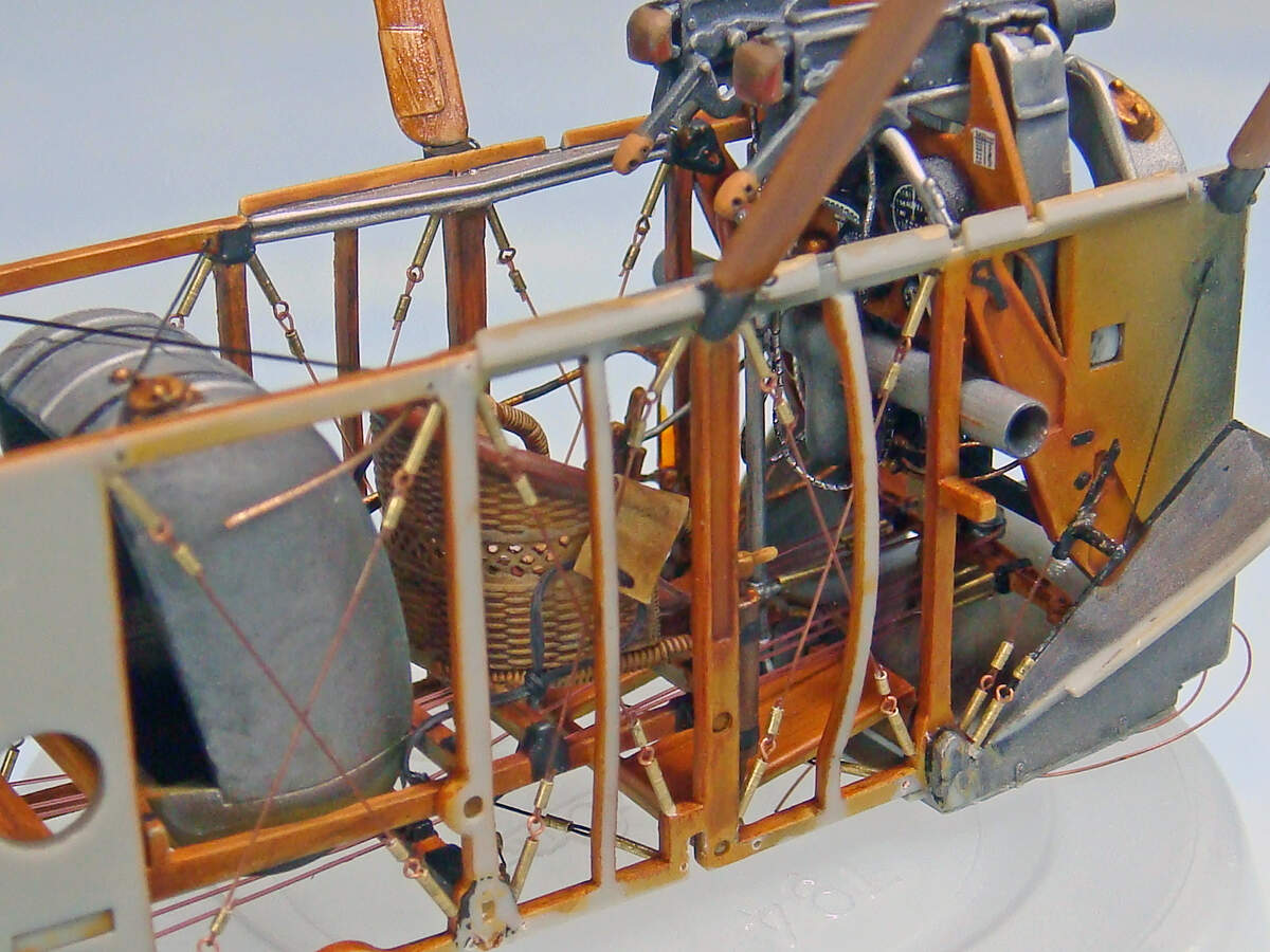
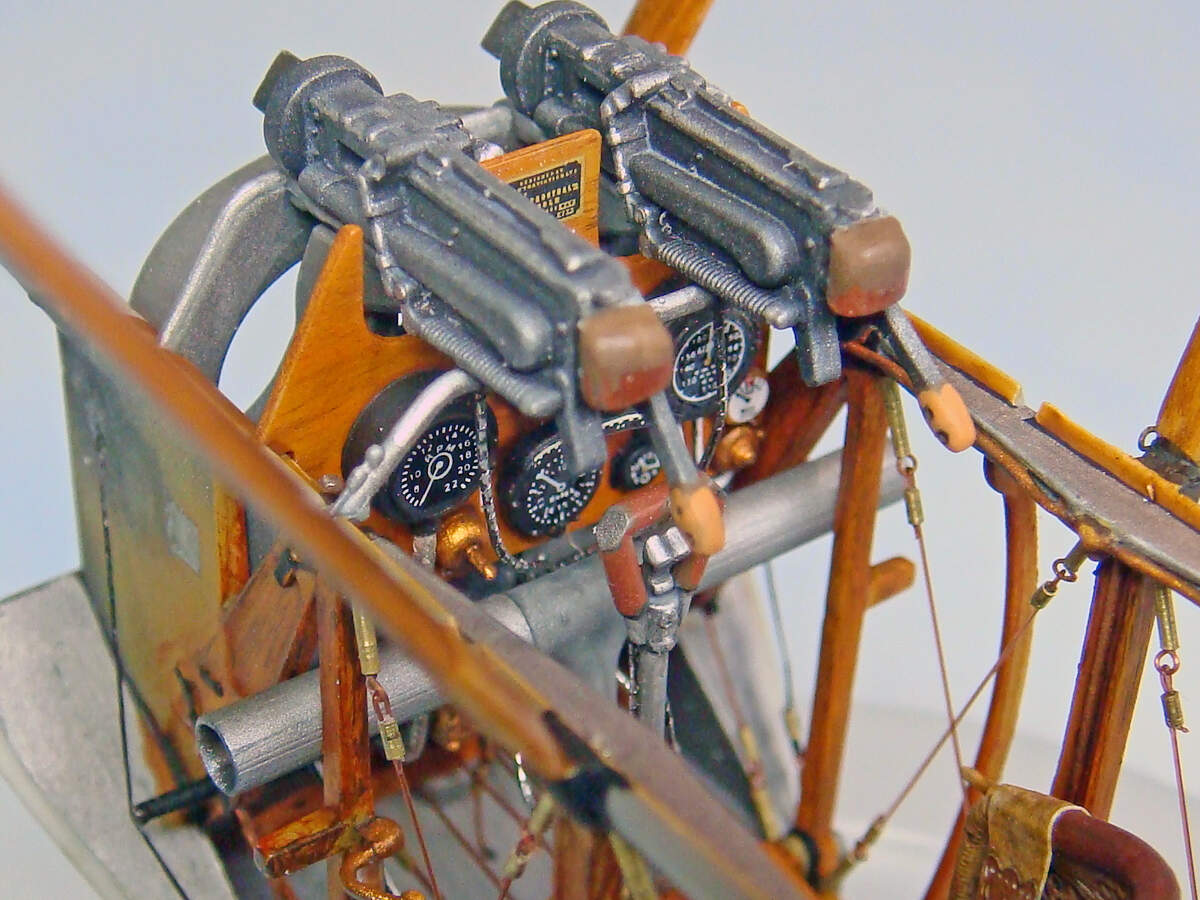
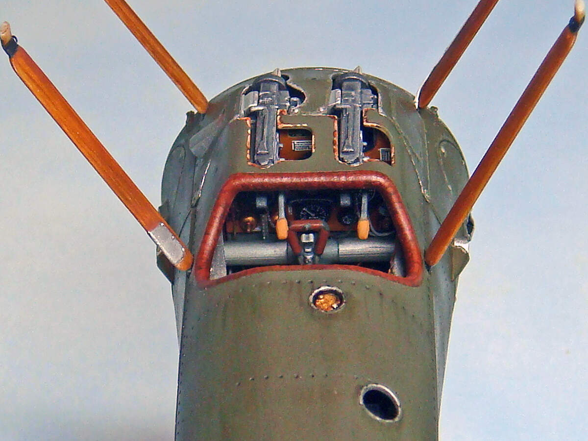
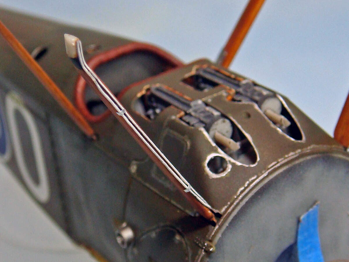
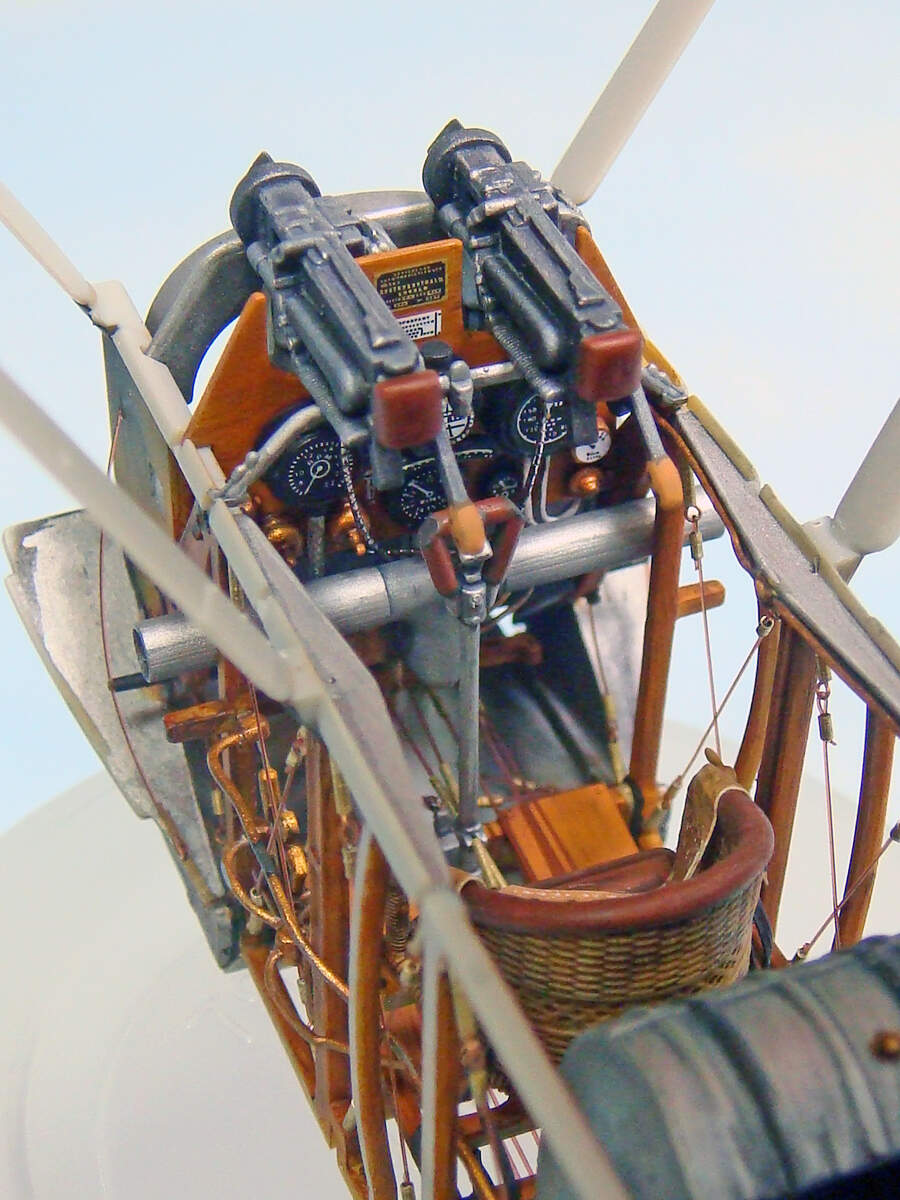
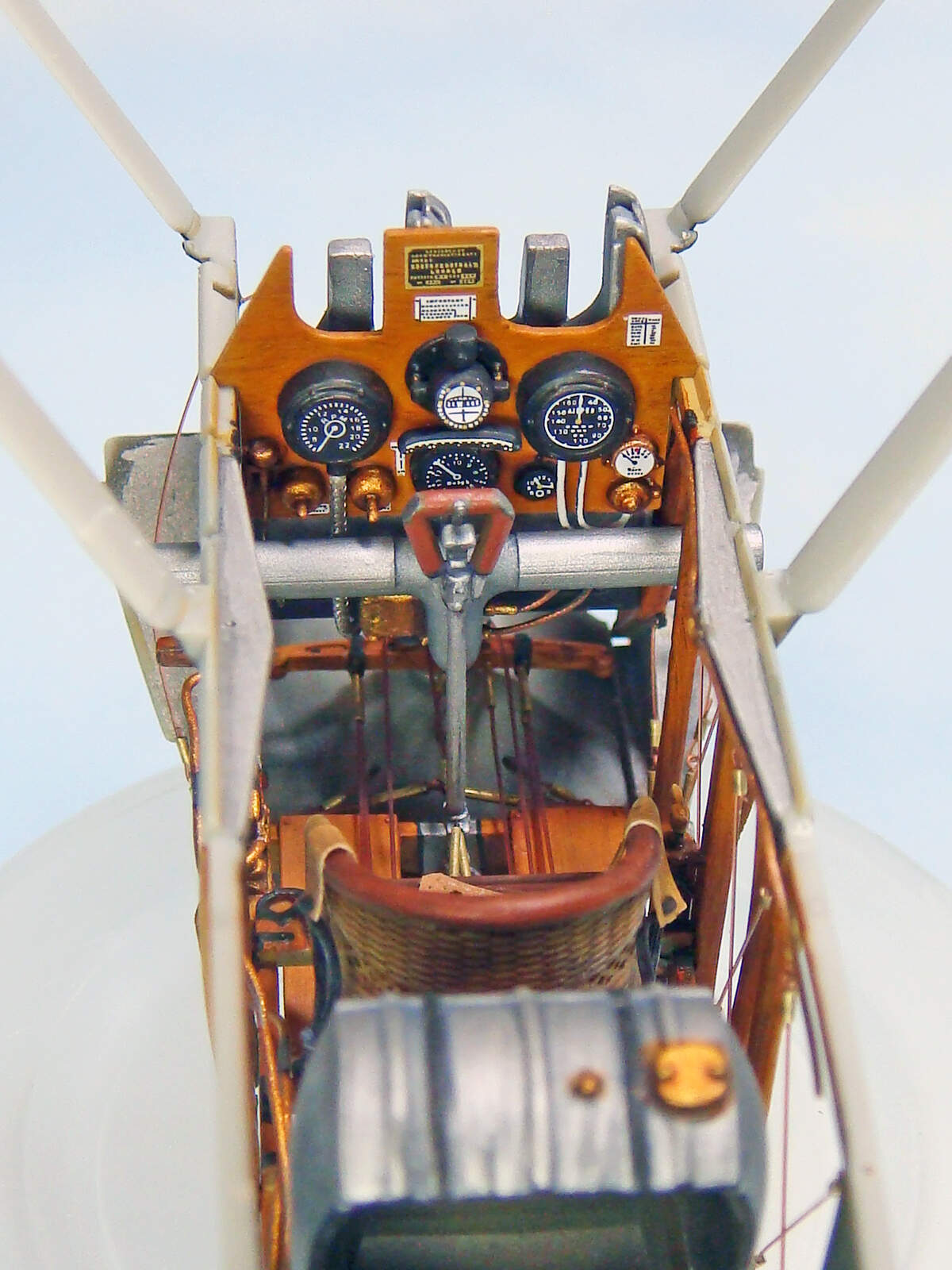
The kit’s Cartograph instrument decals were a perfect fit into the injection molded gages. No trimming needed at all. I did add the switch levers for the magnetos. I also replaced the lines to the airspeed indicator and pulsometer with wire. I have a piece of clear stretched sprue that I’ll add for the pulsometer bulb when I add some Future to the instrument faces.

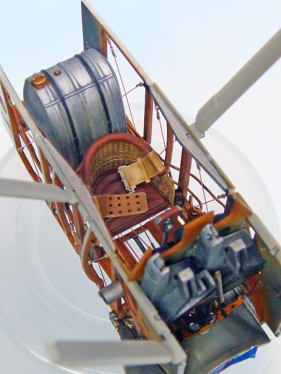
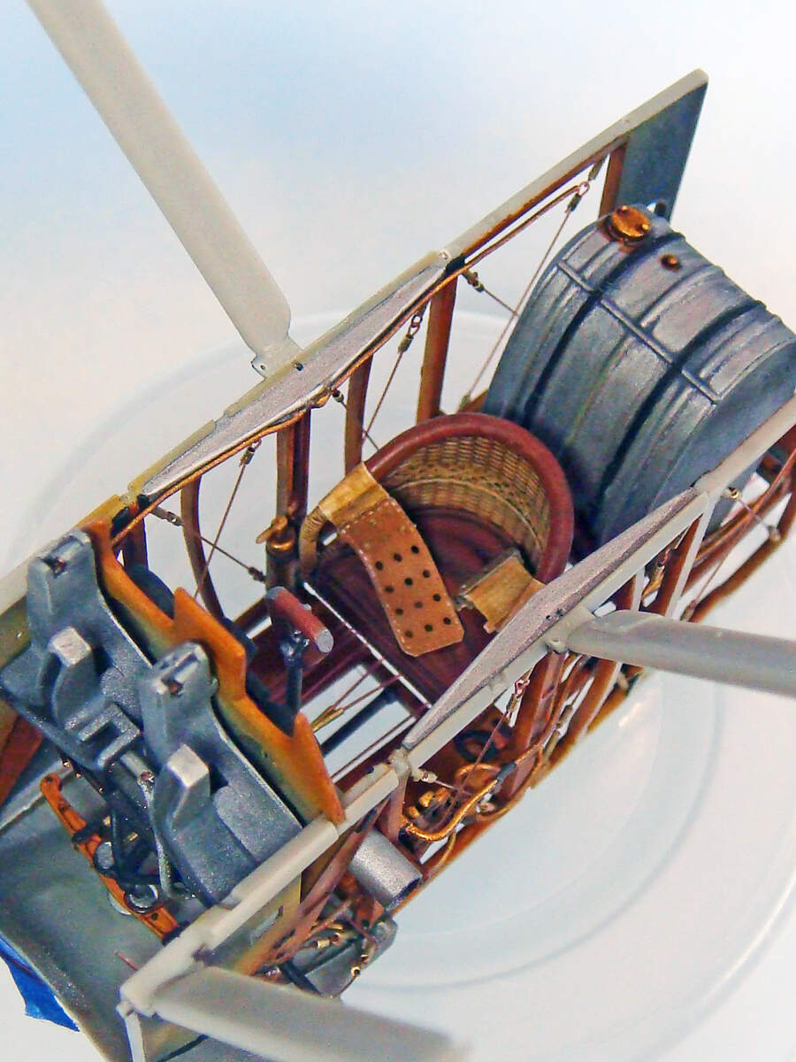
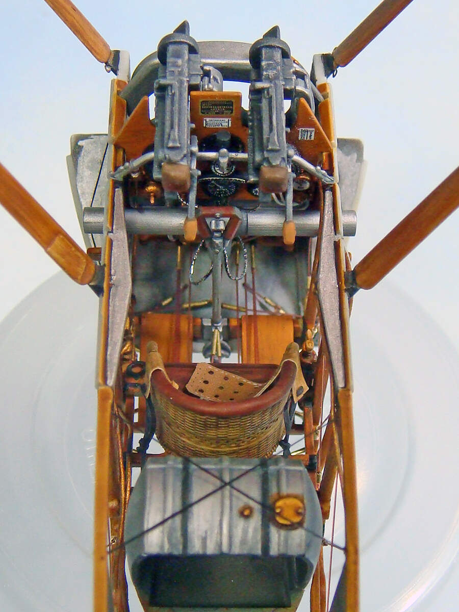
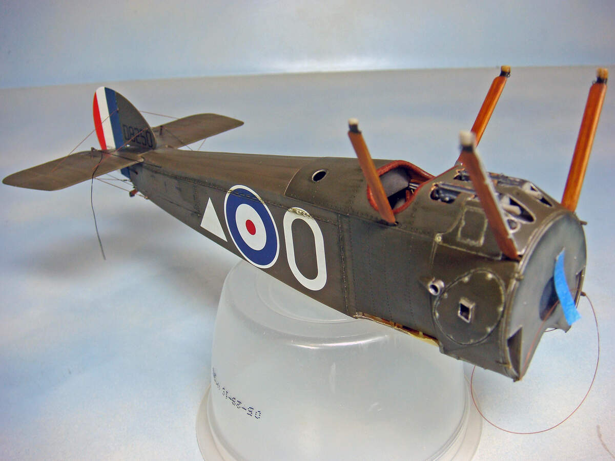
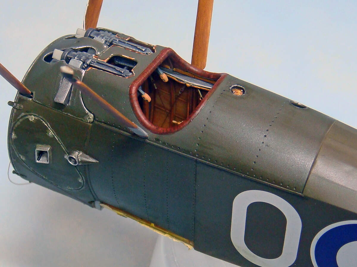
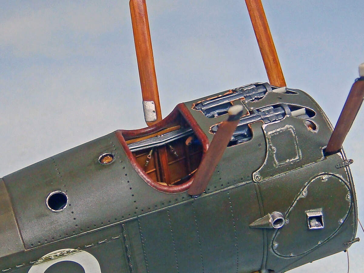
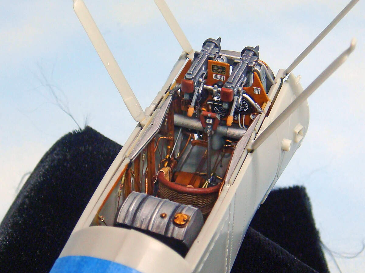
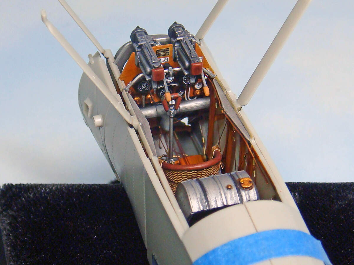
I still have the bracing wires for the first two bays of the floor to add along with the clear parts and gloss on the gages, but these last two shots show the cockpit module test fitted into the fuselage haves. The gaps between the top edge of the fuselage opening and the interior framing are cause by some slight warping of the fuselage parts. These parts are molded pretty thin, though, and the gaps will close up with just a little finger squeeze. The famous WNW parts fit is well deserved.

So… My hat’s off to all the guys and girls out there who regularly build fully-rigged biplanes! I was looking for a bit of a challenge and something new, and I can say that this rigging stuff is a “whole 'nuther kind of model building nuttiness”!

Now onto the fuselage interior…

10 Likes

Looks like you got it figured out. Nice job so far.

1 Like

What a story! Love the “Spring Maid” advertising… straight from the fighter pilot personality.
I like what you have done on the model so far. It looks great! Defiantly wanting to see further progress photos.

Cheers,
C.

2 Likes

Yea, the stories are that ol’ E.W. was quite the ladies man and regular playboy! It’s said that it wasn’t uncommon for him to show up at a friend’s place with a jug of 'shine and a new lady on his arm to party all night long.

He was definitely one of those F. Scott Fitzgerald “Great Gatsby” types.

Here’s another shot of him in later years after the war posing with ONE of his personal planes on his private airstrip at the family mansion out side of Ft. Mill, SC. The guy clearly loved “fast” everything from cars to planes to whatever!

elliott_springs_5

4 Likes

Very beautiful, so far!!! And thanks for the story behind the man.

1 Like

Really nice work on the cockpit. A very realistic finish, especially on the seats leather padding. Looking forward to seeing it finished.

I’m glad I grabbed this kit when it was first released. One day I might even start it, although I don’t trust not to snap off those moulded on cane struts!

@rhwinter Thanks for the kind words!

Indeed, E.W. Springs was more than a mildly interesting guy. The “Captain” or the “Colonel” (as he was known locally after brief WWII service and a reserve promotion to Lt. Col.) was really a local legend. He was actually better known for his ownership and management of the Springs Textile Corporation and local philanthropy than his war record as the #5 WWI American ace or his literary career (which was also quite successful). He still ranks in the top 100 US aces (IIRC ~#75). The older citizens of Lancaster, York and Chester counties in SC still tell stories about him to this day.

@phantom_phanatic Also thanks for the props!

The wicker pilot’s seat is really a quite sturdy subassembly. It’s made of four parts, the seat bottom and cushion, the backrest and the two arm pieces. Once assembled, it gave me no trouble of concerns.

The open wicker weave around the middle of the backrest part is actually molded solid and closed. I used a small drill to open holes between the rattan “strands” and then carefully trimmed the openings into diamond shapes.

The leather was pretty easy, just a base coat of one Vallejo color with a second brushed on the tops of the folds. This then got a couple of different Citadel / Games Workshop wash colors. I’m not up in the shop right now, but if you’re really interested I’ll look up the color names and codes later for you. Normally I would have painted the leather parts in artist oils over the acrylic base coat, but I wanted to try something a little different as an experiment.

The kit is really quite straight forward. The only issues I’ve had so far have all been self-inflicted that I chalk up to my unfamiliarity with the modeling genre and general subject matter. I find myself having to go back and carefully work around earlier work because I’ve not accounted for something that would have been easier to do at some earlier point in the sequence.

Here’re some “happy snaps” from a few days ago showing some more work on the cockpit module.

So, for instance, it would have been easier to paint the wood and add the rigging eyelets on the cabane struts before I assembled the cockpit framing.

Another example is that I’ve had to go back and do more painting on the cockpit framing since I didn’t understand clearly how the fuselage, fuselage decking and cockpit all fit together. After cleaning up the fuselage sides and decking parts and then test fitting everything, I saw areas that should have been painted earlier.

Another area that I had to go back and work on were the leather pads on the rears of the Vickers’ MG receivers. These didn’t fit under the forward fuselage decking. I would have caught this if I had had a greater appreciation for how the front of the fuselage goes together. As it turns out, I mounted the pads a little to high up on the receivers anyway. I spent a lot of time trying to figure this misfit out, grinding the insides of the decking and carving down the tops of the pads.

(In these photos the cutdown pads have only gotten their initial brown paint, so their overall finish is still mismatched.)

In the end, if I was more conversant on the subject, I would have understood that these optional parts should probably have been left off of this particular aircraft since the front of the cockpit coaming and its padding protect the pilot. (The MG padding is probably more appropriate for the aircraft that have the field modified / cutaway decking since then the pilot has no protection from the rear of the guns in an accident or rough landing.)

Another detail that would have been much easier to add earlier on would be the Bowden firing cables that route from the forward side of the control stick, down and up between the air intake and the control panel and then to the MG mounts.

I probably should have added the cables to the control stick and then routed them up to the MG mounts later rather than adding them to the MG mounts and having to route them down to the control stick.

There are other examples of these self-inflicted problems.

No photos to show yet, but I’m having to add the air tubes to the front of the right forward cabane struts for the pitot tubes. On the prototype, these air tubes run from from the pitot tubes up the right forward interplane strut, through the upper wing to the right forward cabane strut, then down the front of that strut and into the fuselage. These would have been easy-peasy to add before the cockpit subassembly was put together and finished. Now, though, I have to work around all of this delicate stuff to add these.

Oh well… Did I mention that I’m doing this to learn something new? LOL!

5 Likes

So, it’s about time, I suppose, to update this blog. I admit that I’m really slow, but in addition to my usual turtle-like tempo, I’m spending about as much time trying to figure out what and how to do as I do actually doing.

Anyways, I’m almost done with the fuselage. It needs some more weathering on the bottom, but that’ll have to wait unto I add the bottom wing and landing gear. (Coming soon, to build blog near you!) I’m still tidying up the tail rigging, but almost done with that, too.

So, this is one of my favorite shots since it really illustrates how the PC-10 color can look entirely different in different areas depending on the angle of the light. In a lot of photos of the real aircraft, the fuselages almost look like they’re painted a much darker shade on the sides than on the top. However, here the rear of the fuselage from the cockpit rear deck to the tail is the exact same color. But this photo shows the same effect as the prototype photos.

The kit decals were used except on the rudder. I painted the red-white-blue stripes using reverse masking techniques (white, followed by the red, then the blue). Conveniently, the rudder was 18 mm wide, and I happened to have a role of 6 mm wide Tamiya tape. “Serendipity,” as the lizard on TV says…

A detail missing from the WNW’s kit are the air lines from the pitot tubes to the airspeed indicator. I made mine from .03 mm dia. lead wire, painted white. I made the little metal clips from tiny bits of Bare Metal Foil.

My references suggest that these lines were made of natural colored rubber and were white-gray like some many other rubber items of the day.

As I mentioned, I’m still finishing up on the tail rigging. I broke one of the elevator control horns off, so its control line still needs to be snugged up and trimmed to length.

All of the rigging, as with the cockpit, has been done with a combination of 2# test monofilament fishing line or EZ Line. The ferrules have been cut from .5 mm dia. Albion tubing (here on the tail, nickel-silver for its natural silver color).

The fuselage framing that shows through the clear doped linen (CDL) on the bottom was painted on using Tamiya flat earth before the deck tan was sprayed for the CDL color. Lots more weathering to do along here, but that’ll have to wait until I add the lower wing and landing gear.

The bottoms of these rotary engined aircraft were apparently a real mess from a mixture of exhaust and castor oil (not to mention dirt and mud kicked up from the landing gear wheels).

6 Likes

That’s beautiful paint work and attention to detail Michael. Which paint did you use?

You’ve also given me a good reminder that I need to get that Rumpler I started on the old site finished.

1 Like

Thanks, Stephen!

Nothing really special with the paint, pretty much exclusively Tamiya for all the airbrushing and Vallejo for the hand painting (with some Citadel / Games Workshop metallic colors and inks).

The PC-10 is a mix of XF-62 OD and XF-52 Khaki at 2:1. The lighter shade is the same thing with 30% by volume of Flat Earth added. I added just a bit more Flat Earth for the rib tapes and shaded their sides with a shade just slightly darker with a touch less Flat Earth.

(I should mention that the dark shade of this this mix is almost a dead-nuts match for Tamiya XF-51 Khaki Drab. I did up some spray-outs to check several PC-10 color mixes and suggestions, and the XF-51 is just ever-so slightly darker than the XF-62+XF-49 mix.)

The CDL is just XF-55 Deck Tan. I added a touch of white for the rib tapes.

I thinned all the Tamiya paints with their proprietary lacquer thinner (“yellow cap” bottle). No magic or stress.

All of these PC-10 colors were very close to the WNW kit recommendations which all start from the same XF-62 OD.

The wood areas are ether XF-59 Desert Yellow (if airbrushed) or Vallejo Iraqi Sand (hand brushed). Over these colors, I just streaked burnt and raw sienna and raw umber artist oils. Once those dried, I gave the wood a wash of Citadel Seraphim Sepia.

For the decals, all I used over a clear gloss (Tamiya X-22) was Micro Set (with a touch of Micro Sol on the areas where there was some fuselage lacing. They went down beautifully with no trouble.

So, a small update on progress. I’ve cleaned up the wing and aileron parts and started finishing them. WNW molded some very fine and subtle scalloping detail on the leading edges of the wings, and their trailing edges are very thin. It takes some care and patience to clean up the sprue attachment points and mold seams along these while avoiding damage.

I also added small pins to each aileron made from 28 gage brass wire. These slip into matching holes in the rear of the wing notches for each aileron. All pretty standard stuff, but necessary for the way I’m building the model. WNW molded on the three very small and fine hinges on the bottom of each aileron, but when the aileron is installed on the wings, these small details are the only attachment points (leaving a thin, prototypical gap between the wing and aileron). I wanted some added strength in these areas, so the brass wire pins.

I also predrilled all of the holes for rigging eyelets and lines. One area that was a bit challenging was opening up the boxed in, angled passage holes for the rear sets of double flying wires. On the real aircraft, these wires pass through the wing root and attach to the fuselage at the intersection with the rear landing gear struts. On the kit, these passage holes are molded solid with pairs of rigging locator holes on the tops and bottoms. I wanted to pass my flying wires through the wings, though.

I tried to simply drill these out and then square them up as I opening them fully. Unfortunately (for me), I found this impossible. The angle of the passage hole is so very shallow to the wing plane that I simply could not get any pinvise or drill close enough to the wing surface to through-drill the proper angle. In the end, I carved rectangular openings from the molded on “holes” (in opposite directions) in the wing surfaces, top and bottom. I then opened up the square entry and exit holes, connecting them through these rectangular troughs. I then went back and filled in the rectangles on the wing surfaces with short pieces of styrene strip stock, filling and smoothing the wing surfaces.

A lot of work, and I guess I’ll have to wait until the final rigging to see how well it all came out.

For the painting, I used the same PC-10 and CDL paints described earlier. To add the shading and preliminary weathering effects, I used Tamiya clear orange on the CDL and smoke on the PC-10. These were respectively mixed with just a very small amount of the deck tan or PC-10 basic mix. I also mixed them with Tamiya clear gloss to make semi-transparent glazes so that I could more easily control their effect and opacity by building up their color saturation over the underlying colors.

To mask the rib tapes, I used 1.5 mm wide vinyl pin-striping tape which was a match for the width of the molded on details.

The most tedious and time consuming part of the masking was the PC-10 wrap under the leading edges of wings. References suggested that the point on the wing tips where this ended varied somewhat, but its presence was pretty much a standard.

So, next up is gloss coating in preparation for the decals, followed by some additional detail painting. My plan is to add the rigging eyelets and then permanently install the lower wing to the fuselage. After that will come the landing gear and final weathering of the bottom of the aircraft.

Tally ho!

5 Likes

Looking great. I have this kit so I have been following as build guide. This is great work. Thanks for taking the time to post this build. I am learning a lot.

1 Like

Ok, so “Camel Wings, Part Duex!” … or, “Camel Wings! Just like Buffalo Wings, only better!” LOL!

Wow, feeling a little punchy after making and adding the rigging eyelets today…

Anyway, the wings are detail painted, decals added, and rigging eyelets added. They’ve also been shot overall with Tamiya semi-gloss to even their appearance out. They’ll get some more clear and semi-gloss later during follow on weathering stages, but for now, it helps to be able see clearly what’s going on with colors, etc.

This is a trailing edge view of the top of the bottom wing.

Next up is a leading edge view of the same thing.

A view of the top right end of the bottom wing showing the aileron pully and cable inspection port and the rigging eyelets at the interplane strut locations.

So a closeup of the same thing showing the details a little better. Note that the forward edge of the aileron and the rear edge of the wing notch for it have been painted a raw wood color.

The bottom side of the bottom wing with the WNW kit roundels and wing contract-part numbers. There’s some uncertainty as to whether or not E.W. Springs aircraft had the letter code on the bottom wing. Some other planes in the 148th Aero Squadron did, but there’s no definitive view of Springs’ mount to prove or disprove this. I thought it added some extra interest, so here it is! (It is included in the WNW decal sheet as an option.)

So a closeup of the shading I added to the kit decal and the other decals.

Here’s the top of the top wing, leading edge view. The top wing is still in three parts, but I’ll glue them together before adding it as a single unit later.

The center section of the top wing showing the bracing wires in the field modified cutout done to improve the pilot’s upward vision. Again, WNW gives optional parts for the standard, factory wing as well as this modification. The bracing wires here were added using Inifi Models elastic thread anchored into “blind” holes with CA. Again, the molded on aileron cable inspection port details are visible. All of these inspection ports will get clear “Perspex” covers later (clear kit parts are provided for them).

End of the top wing showing the kit roundel with airbrushed shading added. Note how the roundel colors carry down into the gap between the aileron and the wing. The kit decals account for this extra color. I must say that I had fits with these decals. The white ink was very thick and resisted everyone of the many different decal solvents I tried on them. In the end, the white ink cracked along the edges where it was to fold over. I even tried one decal cutting the fold and applying as two separate pieces, and the white ink simply lifted and cracked along both edges. (These decals even refused to to suck down tight on the molded rib tape details in places and created some lifting issues in those spots.)

For the record, I tried: Micro Sol, Testors Decal Solvent, Walthers Solvaset, and Gunze Mr. Mark Softer (which melted the decal film but had not effect on the white ink). I had a bottle of Scale Motor Sport Decal Magic that I forgot to get down and try, but honestly, I have no reason to think it would have worked any better. I generally start with the least aggressive decal solvent (when needed) and work my way up the scale, but here, the issue wasn’t the decal film, but rather the thick white ink. On a positive note, the white markings ARE opaque! LOL!

Moving on… The bottom of the top wing.

Finally, a closeup of one of the bottom ends of the top wing shing the part-contract number decals, the rigging eyelets, and the black painted aileron hinge details.

Next up is to permanently add the bottom wing to the fuselage, and while that dries nice and hard, I’ll work on the landing gear and interplane struts.

Happy modeling!

5 Likes

Absolutely stunning work!
Cheers,

1 Like

So for the last few build sessions, I’ve been working on a number of small details and parts - landing gear, the Vickers MG barrels, interplane struts, etc. - in preparation for the final “big push.”

Today was an long airbrushing session where I blocked in all of the base colors on those parts and subassemblies. They all need a good deal of hand painting now, so I didn’t bother photographing them.

However, in anticipation of adding the landing gear in the next few days, I did finally add some of the weathering to the bottom of the fuselage and bottom wing (also finally installed a few days ago). References show an asymmetrical concentration of the exhaust and castor oil staining along the bottom port side of the aircraft. I assume this is because of when the exhaust valves reach fully open they’re down around 7-8 o’clock (when facing the front of the aircraft). Another “quirky” feature is the rather scalloped look where the staining concentrates on the rear portions of each fuselage framing bay (a visually interesting effect).

At any rate, this was simply done with Tamiya X-19 Smoke. This is a semi-transparent gloss color, so unfortunately, there’s some glare in these photos. However, I think they’re good enough to get the idea across. The effect should appear more even later under a semi-gloss or matt clear coat.

(I apologize for the focus of this last photo. )

Happy modeling 'til next time…

5 Likes

Hi Micheal

Although I don’t build WNW personally, I love watching them being built!

So far this is just an amazing build! :slightly_smiling_face:

Can I ask, what is the clear acrylic jig/fixture you’re using to hold the a/c whilst you’re working on her?

Thanks, Russell! This is the first WNW kit that I’ve built, myself. (Heck, it’s the first rigged biplane I’ve built since about 1970 when I did the Monogram Wright Flyer… LOL!)

At any rate, I’ve also admired a lot of them, built and in-progress. I figured it was about time that I gave one a shot. It’s been an impressive kit in regard to design, engineering and production quality, pretty much living up to all the hype.

I confess that the assembly stand / fixture is a bit of an indulgence that I picked up a couple of years ago at an IPMS / USA national convention. I’m only just now using it for the first time. I’m sure I’m not getting all I can from it. For what I’ve done so far, I could have easily gotten away with an open cardboard box. Still, it’s growing on me…

This one is the Virtego Miniatures, BI 3224:

Vertigo Miniatures, BI 3224 Assembly Jig

3 Likes

@SdAufKla I hear what you’re saying Michael. The WNW kits look lovely and I’m sorely tempted by them, but display problems and stash challenges have kept me away, and so I’m happy to stick to my 1/72 kits for now and watch happily from the side lines :slightly_smiling_face:

You’re doing such a good job, I’m not sure I’d get anywhere near close.

I did have a go at Airfix’s Gloster Gladiator recently and it was a most enjoyable kit to build…

Thankyou for the Vertigo link: I think one of their products will be winging its way to my workbench very soon :relaxed:

1 Like

Cheers!

1 Like

Although I haven’t posted up any earlier photos, obviously I’ve now added the bottom wing. (I didn’t realize that I hadn’t posted any photos of that yet…) The model is finally looking like an airplane, though! LOL! Seemed sometimes like I’d never get here.

I’ve also been pegging away at some other details (again, not shown) like the interplane struts, the Vickers MG barrels, the Aldis gun sight and the windscreen. All of those have been finished and are ready to install as I progress through the rigging. I also have the top wing assembled in readiness to pre-rig it.

Finally, I’ve added the landing gear and weathered and rigged that. The wheels as shown in a couple of these photos are just dry-fitted for now. They still need some more weathering to match the bottom of the fuselage.

Before I add the pre-rigged top wing, though, I wanted to pre-rig the cabane struts. After a couple of test fittings of the top wing, I thought I’d have a lot of trouble accessing the cabane strut eyelets, so I’ve anchored the bottom ends of all four bracing wires and threaded their top ends. The top ends are still loose so they won’t pull the struts out of alignment. However, all their wires should need is a couple of gentle tugs, a dab of CA, and then “snip-snip” to trim away the excess.

I have a plan for the forward crossed bracing wires and “acorn” for when the top wing gets added that involves some more pre-rigging. Hopefully it’ll work out. We’ll see.

Most of the work since I added the bottom wing has involved some additional weathering and adding and rigging the landing gear. (The loose line curled over the bottom is the running end of one of the cabane bracing wires… Sorry, I didn’t notice it was in the picture until now.)

The fuselage bottom still needs a shot of some flat clear to eliminate the “shinies,” and I’ll do that soon. I’m still working on the wheels, so in the interest of efficiency, I’ll probably wait a until those are done to shoot the final flat coats here and there on the bottom.

The “Palmer Cord Aero Type” decals are from the kit. I did try to emphasize the very slight radial wheel spoke ripples in the wheel covers. WNW does mold this detail into the parts, but it is so very subtle that unless you’re holding the parts at an angle under strong light, the ripples are essentially invisible.

WNW also molds in some spoke and valve stem detail that is visible through the tire inflation hole. If the light is just right, it is actually possible to see this. I had considered trying to replace this with separate spokes and valve stems, but now I’m glad I didn’t. The kit details look good and are enough, really.

I did add all of the rigging eyelets to the landing gear struts and fuselage bottom before adding the landing gear. There are two horizontal bracing wires with center clevis adjusters that I also added to the landing gear subassembly using elastic Infini Models line. The elastic line easily stretched enough to allow the struts to spread out to fit into their mounting holes.

The landing gear was also weathered as a separate subassembly at the same time as the bottom of the fuselage and wings to make it easier to control the weathering effects, concentrating them in particular areas.

'Til next time… Happy modeling!

7 Likes