Once again I must compliment you on this EXCELLENT build!
Maybe AWESOME would be a better word!
Cheers,
1 Like
 Thanks for the kind words, Joe!
This Camel is looking really good! Very impressive and realistic results all around.
Motivating me to picking up my first plane build in years but not going near a biplane for now.
1 Like
That looks excellent Mike. Those planes look so difficult to get right, I don’t think I could one.
Don’t sell yourself short, Richard. With good basic skills and practices, I think this kit is well within the abilities of most modelers who have a few successful builds under their belts. Aside from the rigging, the construction is pretty much like any other aircraft model. The critical issue always being symmetrical alignment of the wings and tail surfaces. This is just one of the things that aircraft modelers have to deal with, though, like suspension complexity, parts count and alignment on armor models, high-gloss finishes and decals for auto modelers, or railings and rigging for ship modelers. Every modeling genre has its own special difficulties, but dealing with all of them is mostly a matter of applying basic modeling skills.
The WNW Sopwith Camel’s plastic part assembly is pretty straight forward. The kit’s design, engineering and production quality are all very high, so things fit and go together exactly as shown in the instructions. Fit tolerances are very snug, though, so cleaning up even the tiny mold seams and sprue connection points is definitely necessary. Care needs to be exercised with painting subassemblies so that any paint that gets on their mating surfaces is cleaned off (by careful scraping, sanding or masking before painting).
The rigging issue certainly complicates things, but there are different approaches and materials that can be used, some of which are easier than others.
Wing Nut Wings recommends the use of one of the various elastic thread materials (EZ Line, Inifni Models line, Usche rigging line, etc.) anchored with CA glue into blind (or through) holes drilled in the kit. All of the rigging wire and line locations are molded into the kit parts and are pretty clearly depicted in the instructions, so drilling the holes is straight forward. (You do need, of course, a pin vise and #80 drill bits.) The attaching hardware can be simulated with dabs or balls of white glue painted after drying.
I’m using that technique for a number of the wires and cables, especially for those that connect to very delicate features like control horns on the rudder, elevator and ailerons. It takes a bit of coordination to stretch the line while inserting it into second hole while also adding CA and accelerator. The process is simpler and quicker if the second hole is a “through hole” and the line can be tensioned held by cross-locking tweezers on the far side. This makes adding the CA a breeze. (Of course, the line has to be trimmed on the far side and that end of the through hole filled or hidden.)
The other technique that I’m using with monofilament line and small metal tube ferrules is admittedly more complicated, but only just a bit. It’s much more time consuming since the rigging eyelets must be made and the micro metal rubbing bits have to be cut. This is all just tedious repetition, though. (And Albion Alloys actually sells pre-cut, 4mm x .5 mm tubing that can be used instead of cutting your own.)
There are numerous on-line tutorials on this technique. Variations include using Gaspatch, RB or other brands of pre-made turn-buckles, and other rigging hardware.
Next hardest, IMO, would be using PE flat wire rigging materials with or without pre-made rigging hardware. There seem to be a number of variations used with this material to anchor it, and the PE flat wires must be carefully measured and cut to fit each location. The PE flat wires can’t really be tensioned, but they will expand and contract with temperature changes, so if they’re not installed to allow at least one end to free-float, they can sag and bend (which, in my opinion, ruins the effect and advantage of carefully replicating the flat wire rigging).
Bottom line, though, is that there have been thousands of modelers who have gone before us both and figured all of this rigging stuff out and who have also taken the time and effort to share their techniques, materials and tips. Finding detailed instructions is not hard, and with a little practice and patience, I believe that replicating one of these techniques can be done by just about any modeler.
I wouldn’t suggest that someone try to build one of these as his or her first kit, after some practice and experience, there’s nothing mysterious here.
2 Likes
I’m sure I could if I put my mind to it and started out with something simple. Those kits are becoming so popular I see them increasingly at area model shows here on LI. They are very interesting too with their camo schemes etc. I may have to take a brake from armor/ figures and do a ww1 biplane lol. The last and only biplane I ever did was when I was 9 or 10 and we did them for a Cub Scout project lol, over 50 years ago!
I actually have a hankering to do a Blackhawk DAP with live resin pilots and SF crew
1 Like
I hear ya… I periodically take a break from armor modeling to do something different. I’ll also bounce around subject eras, so not always WWII armor although that’s always been my main focus. I usually find a change in genre or era (or both) helps me keep fresh and interested in modeling. Plus I almost always learn something that I can use later on some armor project.
Thanks again for checking in here!
Thanks for the heads up on the biplanes !
@SdAufKla Lovely work Michael 
@metalhead85 Richard, I concur with Michael. Don’t sell yourself short. Like anything else it’s a matter of having a go and practice and be willing to take the risk that it might not always turn out how you’d like, but sometimes it might even be better
1 Like
Thanks for the encouragement guys !
(Oh it was about 45 years ago I did my only biplane lol)
2 Likes
So, as with a lot of modeling projects that are done in stages and subassemblies, there reaches a point where a lot of those things all come together very quickly. The build seems to just poke along at a snail’s pace, then… wham-o! All of sudden this starts to look like an airplane!
Here’s the pre-rigged upper wing. This work actually went very quickly. The eyelets have been installed for quite a while now. I cut a bunch of short Albion tubing sections (.5 mm OD x 2.25 mm L), and it didn’t take long to lace up all the wires.
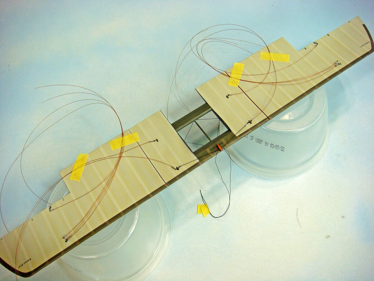
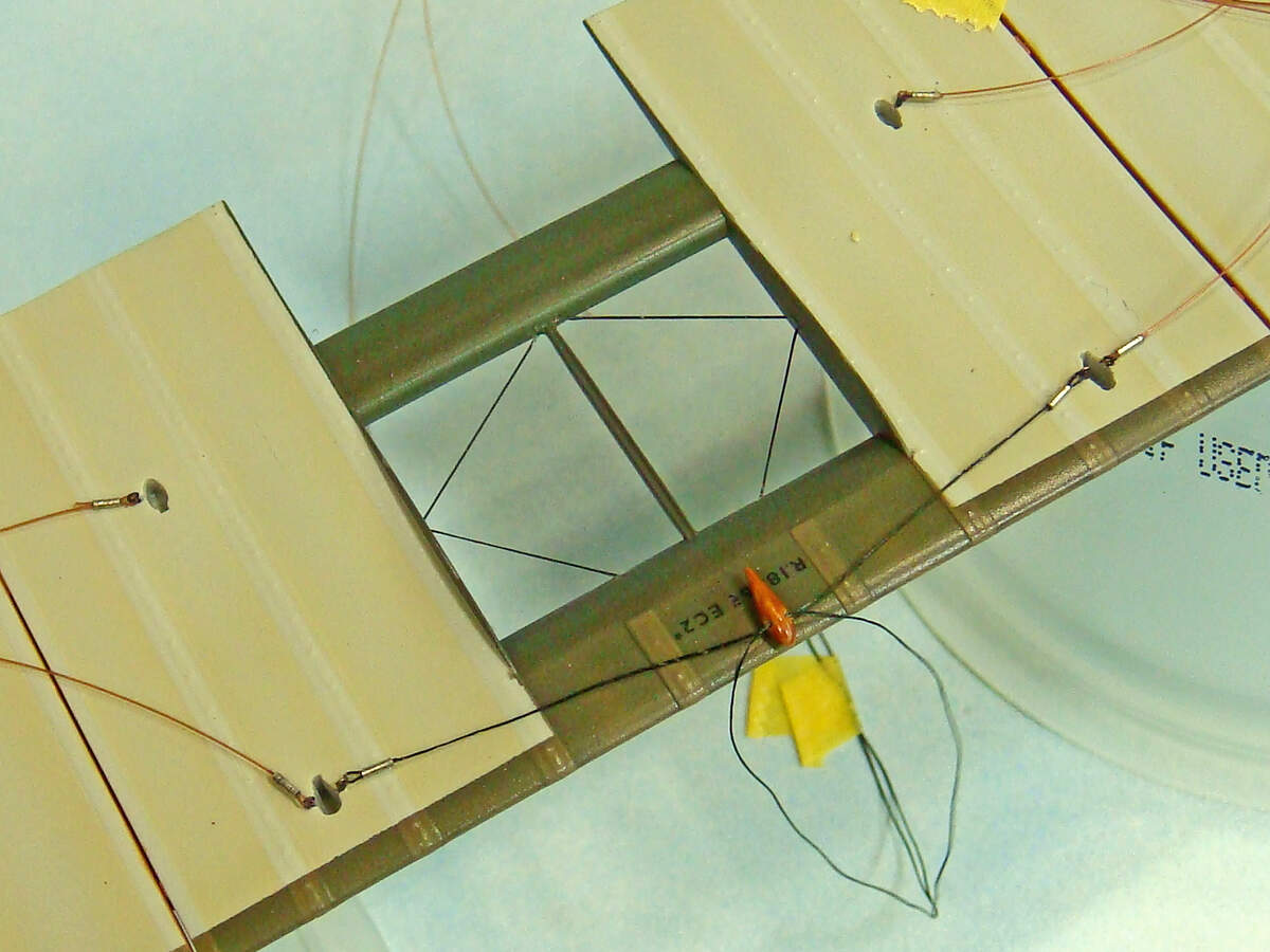
This close up of the center wing section shows how I pre-rigged the front crossed cabane strut brace wires and “acorn” tensioner. The tensioner is a kit part. After I cleaned it up, I cross drilled the two sets of rigging hole locator dimples. I threaded the top hole with a piece of Infni Models elastic line, then rigged it over a 5mm thick spacer to slight tension. When correctly positioned later, the acorn sits 7 mm below the top wing. I then threaded a second piece of elastic line for the lower fuselage attachments.
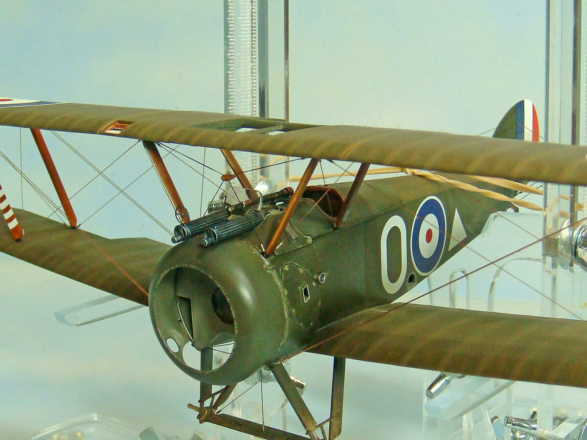
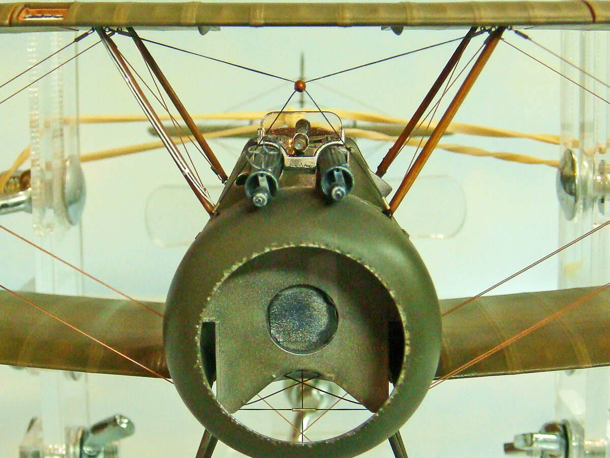
I then installed the interplane struts and the Aldis gunsight and windscreen. I did one more dry-fit test of the Vickers MG barrels to be sure they will fit under the windscreen later. I’ve left them off for now to keep them out of the way, though.
So a closeup to show you what all that fuss about the gunsight and windscreen was about. As with all the rest of the kit, these fit perfectly. I did drill out the ends of the gunsight. I painted these holes bright silver and filled them with a clear gloss to simulate the sight lenses.
BTW, the Aldis gunsight was NOT a telescopic device (despite looking like something the captain might whip out on Pirates of the Caribbean!). It was a coincidence optical sight that had no magnification (i.e. 0X power). It worked pretty much like a modern “red dot” rifle sight with “point of aim being the point of impact.” There was no observed parallax, so the pilot didn’t have to hold his head or eye in coaxial alignment with the sight. What he saw in the ocular lens with regard to target-gun alignment was where the guns were pointing. When he had sight-target alignment at any viewing angle, he could fire. Quite sophisticated for the day, and highly prized by any German pilot who could get one from a downed Allied plane.

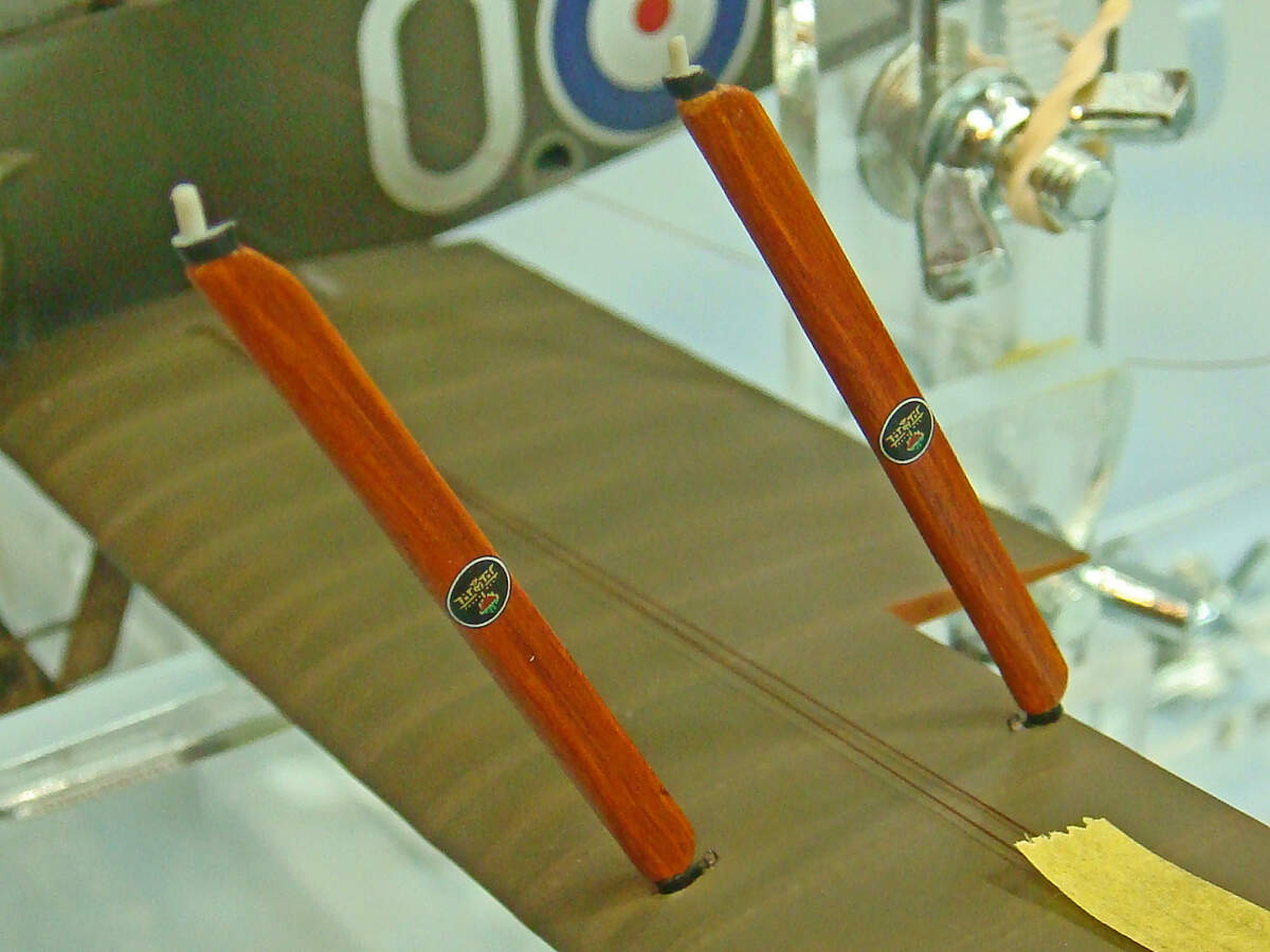
The interplane struts have been prefinished and decaled with the Ruston & Proctor manufacture’s logo decals. The forward starboard strut has the pitot tube air lines replaced the same as the forward starboard cabane strut. I’ll add the pitot tubes later made from some fine metal tubing.
The six white “victory” stripes on E.W. Springs aircraft were masked and painted on. The kit provides a decal for these, but with the trouble I had with the white ink on the decal roundels, I just avoided any potential trouble and airbrushed these one.
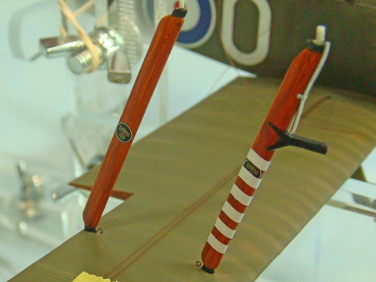
The port side struts just get the maker’s logo decals.
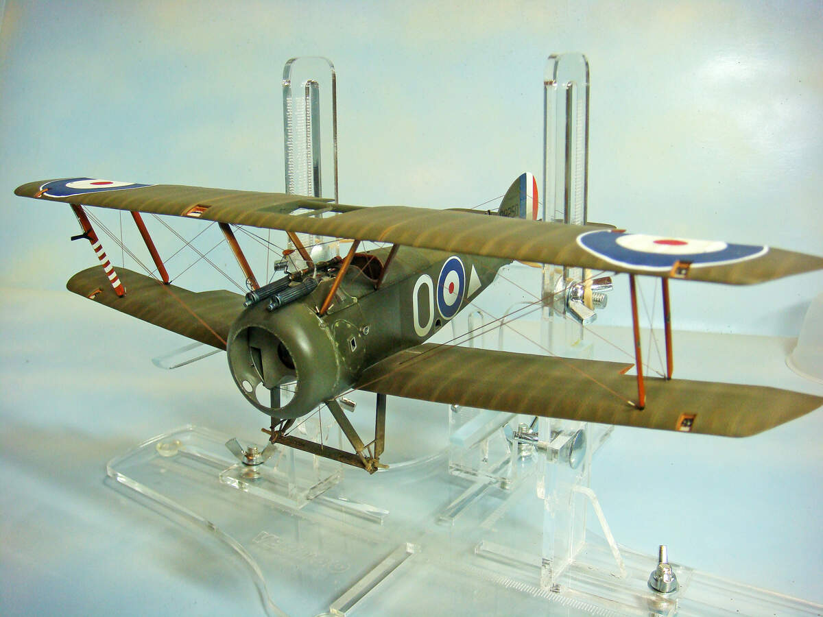
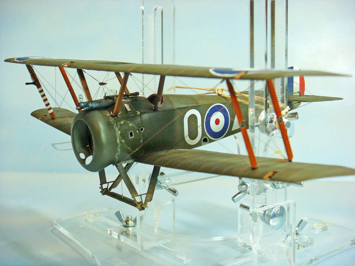
Finally, the top wing goes one, and… voila! It’s an airplane!
Not much to say about this except that it’s a fiddly process trying to line up the struts with their holes. I suggest starting on one end, do those two wing struts, then move to the cabane struts on that same side. The opposite side cabane struts go next, then the other two interplane struts. Sounds easy…
I obviously glued my top wing together and installed it as a single unit. This is NOT the sequence recommended by the WNW instructions, though. WNW shows installing the center section first to the cabane struts, then adding each outer section and struts, one side then the other. This is no doubt the easiest assembly sequence. However, I’m not sure how you would deal with any top wing alignment issues if you had any.

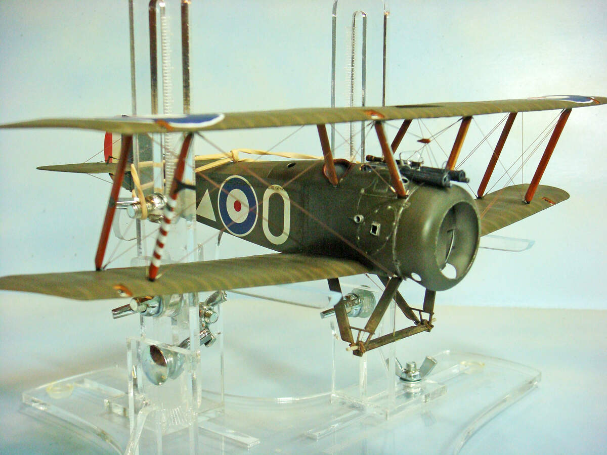
Here’s a closeup of that forward cabane strut cross bracing wire thaaaang… The fuselage rigging eyelets are located at the bottom forward edges of each forward cabane strut, and they should be pretty easy to access and rig. The acorn is not glued or otherwise attached the elastic lines. It SHOULD freely slide and find its center position once he bottom line is rigged.
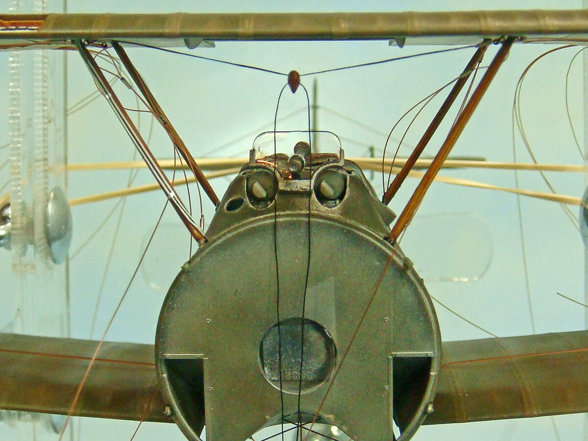
And one final view of the rat’s nest of rigging lines. Hopefully, though, I can just methodically work my way through them, one by one.
Conventional modeling practice suggests that this is best done working from side to side. So, do one wire on one side, then move to the other side to do its mirror. Back and forth, side to side. Also, work from inside out. So, first the cabane strut bracing wires, then outboard.
I do think that I’ll do the cabane strut bracing wires, then I’ll do the interplane strut incidence bracing wires to ensure the top and bottom wings are lined up evenly front to rear. Then the landing wires side to side, followed lastly by the flying wires, rear ones first, side to side, then the front ones, side to side. That’s my plan, anyway… LOL!
Happy modeling!
5 Likes
So, the rigging is pretty much finished. All that’s left are the control cables for the ailerons. My experience thus far suggests to me that those will be quite easy to add.
After yesterday’s big progress, I wasn’t sure how quickly the rest of the rigging work would progress. I was surprised that I got it all done in just a couple of hours, to include cutting another 12 sections of micro tubing.
I pretty much followed my plan as described in the last post. There were a few moments now and then that I misrouted some line or another behind or in front of one of the others and had to unlace the ferrule and eyelet then do over. Not too aggravating, though.
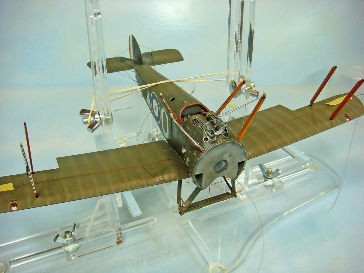
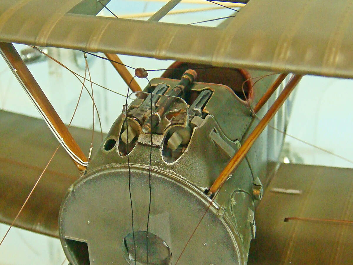
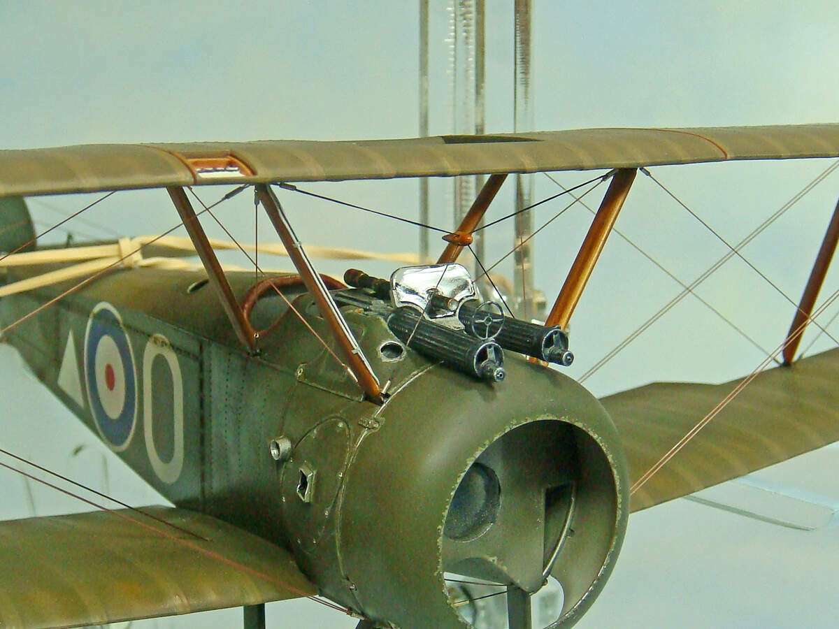
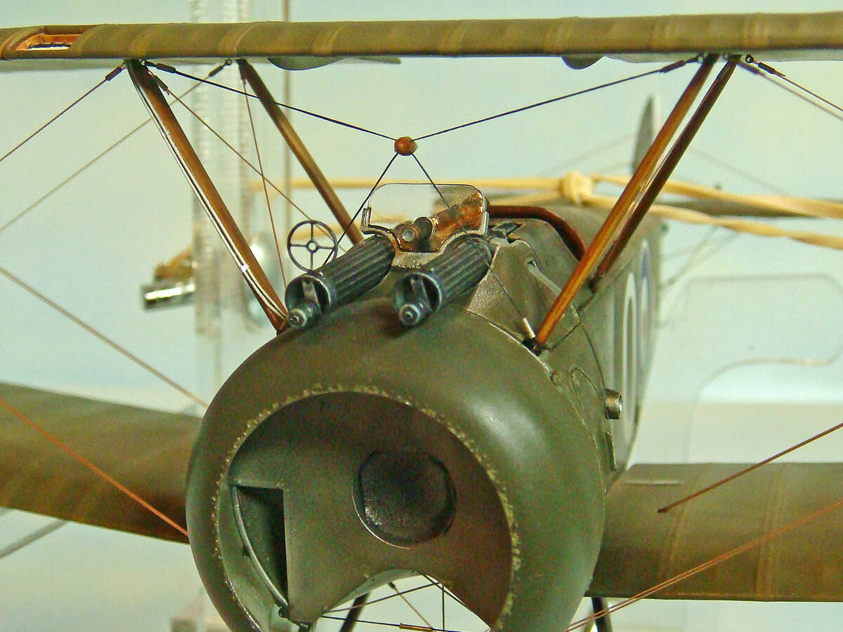
I am happy to say that the front cross bracing wires and acorn tensioner worked out just the way I had hoped. It was actually the easiest bit of the rigging done today. In this photo, the MG barrels and engine cowling are just dry-fitted because, well, just because I wanted to see how they looked! That’s why! LOL!
There’s no definitive evidence that E.W. Springs’ plane had the ring sight on the Vickers, but many aircraft in the 148th did. He was a very experienced combat pilot by the time he flew this bird, and there were constant issues with the front, objective lens of the Aldis sight getting fogged up with castor oil exhausted from the engine. I imagine that Springs would have wanted every possible advantage he could get, so I added the backup ring sight.
The gun barrels will be correctly aligned during final assembly, but even dry fit they are pretty straight.
I think if I ever build another of these Camels, I’d through-drill the acorn tensioner and insert a piece of .5 mm OD metal tubing through it rather than drill the two, parallel holes. I think the metal tubing would be strong enough to allow this to be rigged with the same monofilament line. However, the elastic Infini Models line looks good, and I’m happy with the way it came out.
I did have a couple of the rigging eyelets that turned out to be a little difficult to lace the monofilament through. In particular the two flying wire eyelets on either bottom side of the engine fire wall. I would make the shanks on these about .5 mm longer on another go.
Aside from a few minor, niggly things, though, the rigging went very quick and easy. I was surprised when I was done.
Again, the engine cowling is just dry-fitted here, and it’s a testament to the WNW kit that it quite literally gently snaps into place
Again, I’m quite pleased with the results so far.
Happy modeling!
7 Likes
Stunning work on the Sopwith Camel. Just a word of praise on the blog and your writing abilities. This blog could easily be converted into a book on how to build the WNW model. Your explanations, processes and photographs are clear and easily understandable. Like any accomplished modeler, you make it all sound so easy and within reach of builders of all levels. Kudos to you on a great build and a great blog.
Cheers,
C.
Very nice of you to say that, Charles! I really do appreciate it!
However, for any who wants to see some of the very best WNW builds ever done (at least to my knowledge), I highly recommend these two books:
AFV Modeller Publications :: Wingnut Wings, Volume 1
AFV Modeller Publications :: Wingnut Wings, Volume 2
Sadly, vol. 2 is OOP, but it can still be found at reasonable prices on the secondary book market. These are the modelers and builds that I found inspirational and motivational when I decided that I wanted to dip my toe in the model biplane genre.
1 Like
Great work Michael! The wings look perfectly aligned
1 Like
Here here!
Michael , I think you’re nudging me closer to actually trying one of these kits like we discussed lol! First I have to reduce my substantial stash of armor and figures lol. Incredible work bro
Rich
1 Like
Marvelous eye candy no matter where you look!
1 Like
Progress continues.
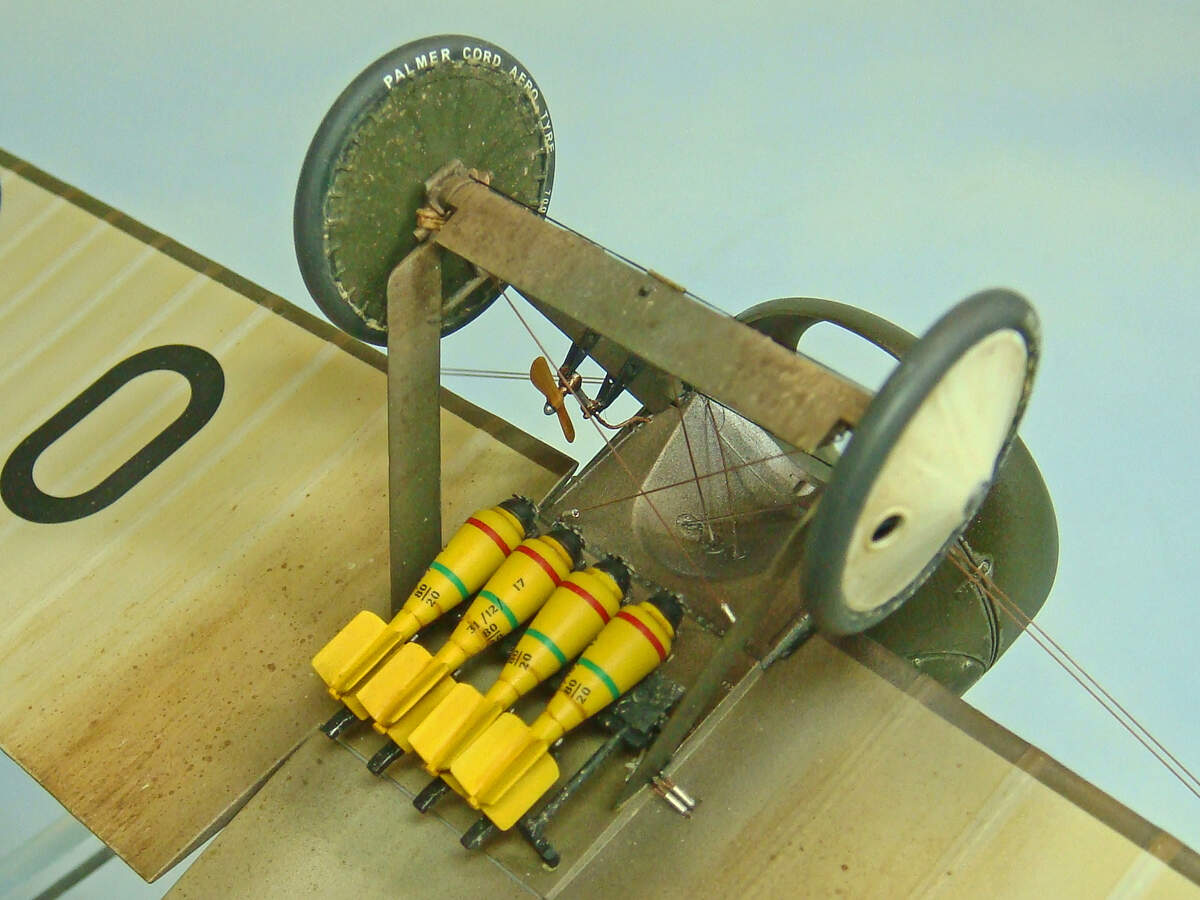
The Rotherham wind-driven air pump (used to pressurize the fuel system) has been added to the landing gear struts. I did add a air line made from a piece of brass wire to the kit parts.
The wheels have been weathered and added. The axles are quite thin and delicate, so I’d advise allowing the glue to dry hard overnight before handling the model after adding the wheels. They also fit rather loose with a lot of play. Some attention is needed to prevent any toe-in or or toe-out and to keep the camber equal, side to side.

The Cooper bombs and bomb rack have also been added. The bombs are probably the weakest parts in terms of assembly fit that I’ve found in the entire kit. They seem to have been designed and engineered well, but the molds in the tail fin area seem like they were cut too shallow leaving small steps between the mating surfaces. The result is that the bomb casing halves fit good and create nice, round cross-sections, but there were gaps down the centers of the tail assemblies. These gaps are at the roots of two opposite sets of fins and a real PITA to fill. The fins were also very thick and “chunky” requiring a lot of careful, tedious filing, sanding and scraping to thin them down.
On the other hand, the bomb decals were very nice and went on well. I did need to use a bit of solvent to get their rear edges to lay down smoothly without any puckers. The bombs are not simple cones, but rather a complex ogive shape, so the decals have a little trouble conforming where they wrap around the tail fin assemblies.
Finally, I also added the HGW PE bomb spinners along with a few PE bits on the bomb rack. Honestly, I’d suggest the Eduard WNW Camel PE set for these parts if you can source it. The HGW PE (actually made by Eduard) is a generic set, so the bomb rack parts had to be modified to fit.
The bombs were only give a little bit of contrasting wash, and the bomb rack was finished and weathered before I added it to the plane.
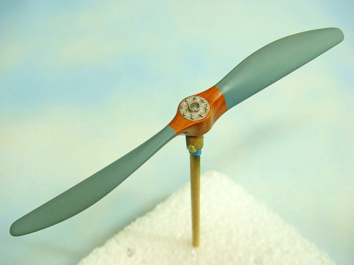
The prop is still in progress here. It has a data decal yet to be added along with some contrasting detail painting and washes on the hub details. The lightening holes also need to be picked out in a medium wood color to match the prop.
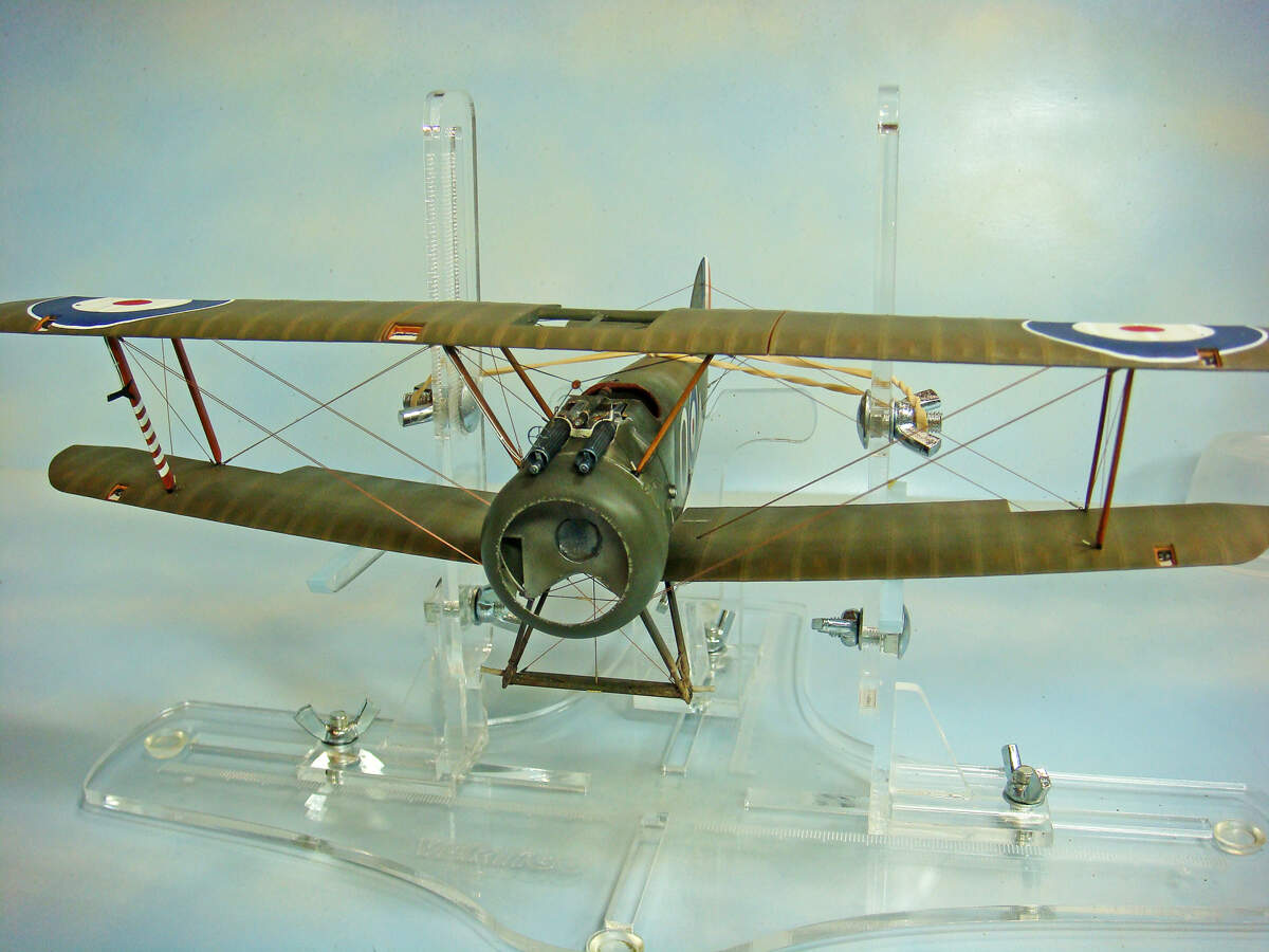
So, this is where the Camel is at right now. Rigging is all done, to include the ailerons. In these photos, the MG barrels and engine cowling are still just dry-fitted.

Obviously, next up is the Clerget engine and finishing the prop.
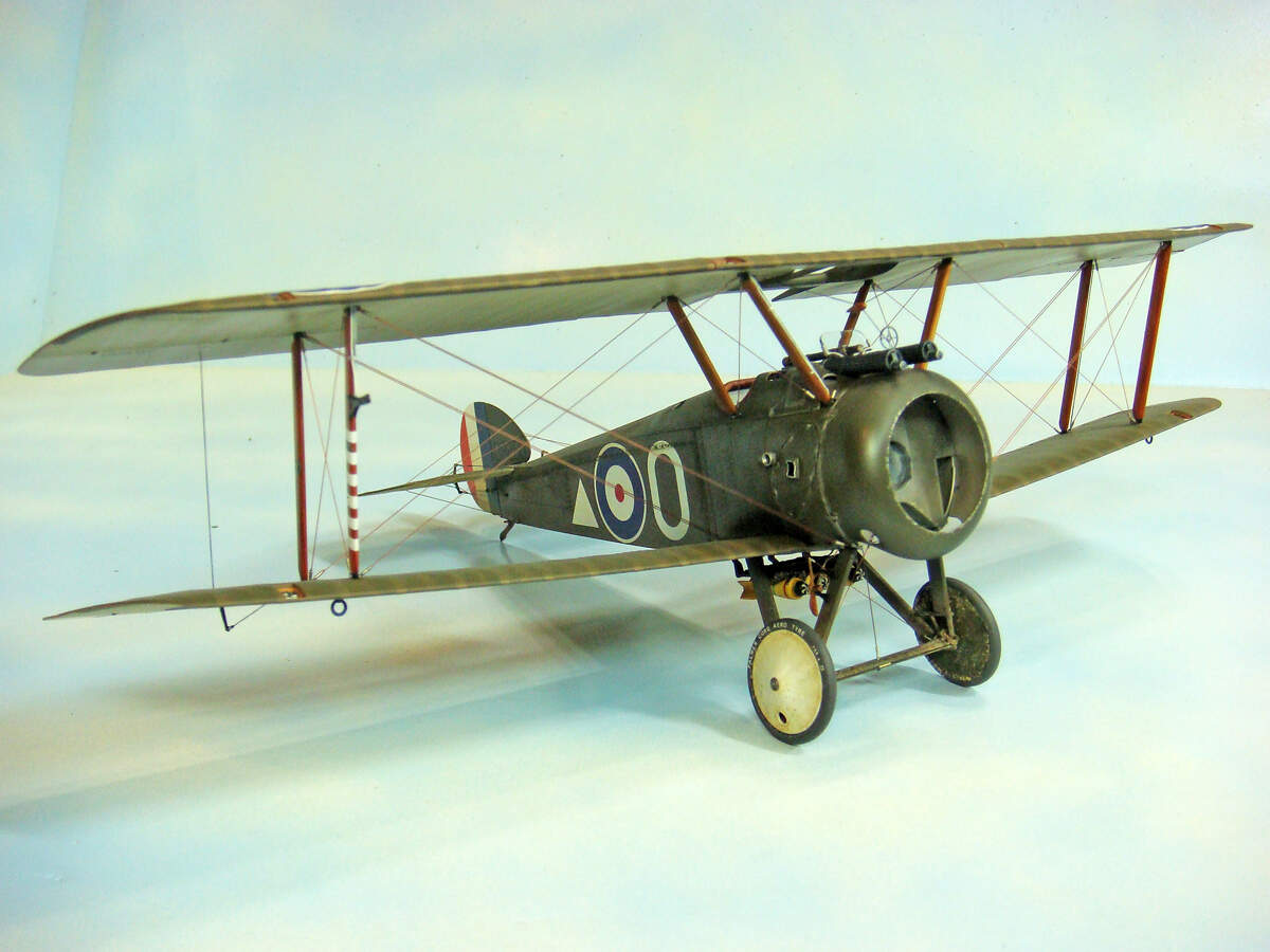
The final details will be the clear covers over the aileron control cable inspection ports on the wings and the pitot tubes. I plan on using the kit clear parts for the inspection port covers (unless there are some major fit issues, which I don’t really expect). The pitot tubes will be made from some fine, .4 mm OD aluminum tubing.
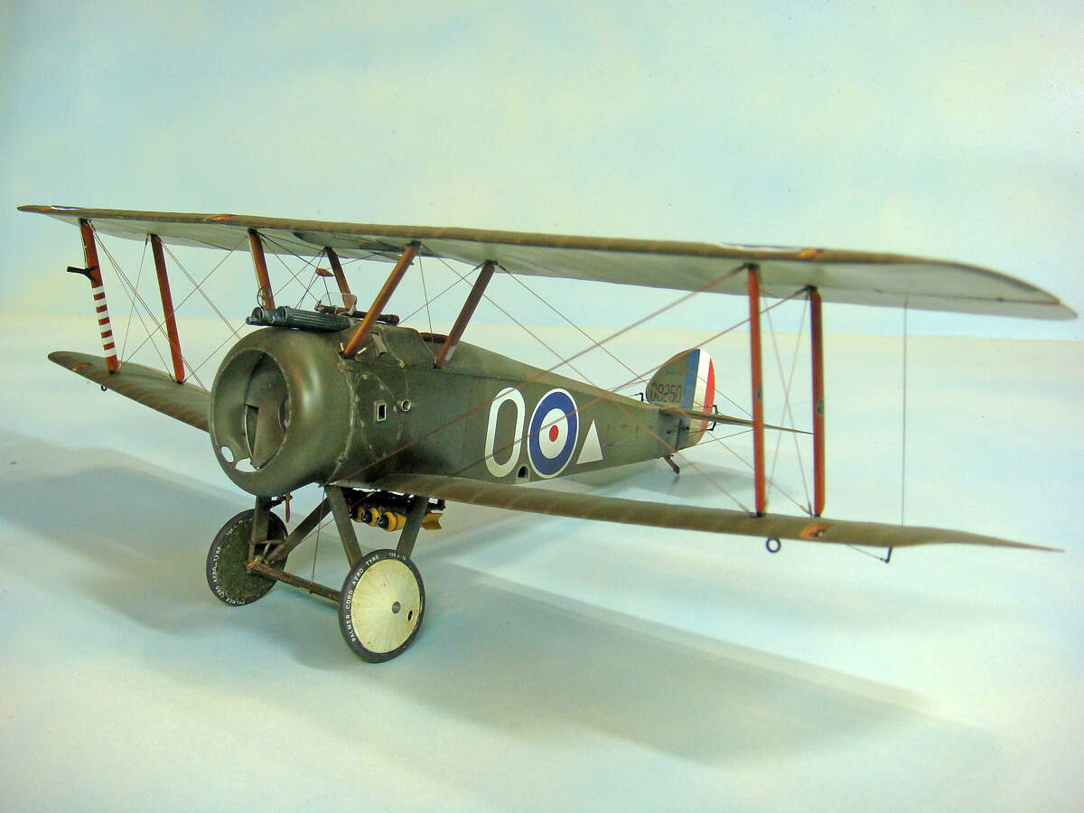
I’m also planning a simple grass covered base and probably adding a pilot figure. I haven’t quite settled on which figure, yet. I really want a standing figure wearing the Sidcot flying suit, but surprisingly, there are very (very!) few to chose from.
8 Likes
Wow! That is one stunning build. I love following along as you progress. Thank you for sharing! 
—mike
1 Like
Love your work Sir. Asked the same question regarding pilot figures. Looking forward to the base choice.
1 Like