WIP of T97E2 track for M48 and early M60 tanks. All I need to add now is the center guide teeth.
Almost there…
WIP of T97E2 track for M48 and early M60 tanks. All I need to add now is the center guide teeth.
Almost there…
Looks great. Changed a few of these over the years. Here a link showing the parts (you might have seen this).
OK, T97E2 track CAD done! Spent too much time on the center guide horns even though they’re not that visible in 1/35 scale…
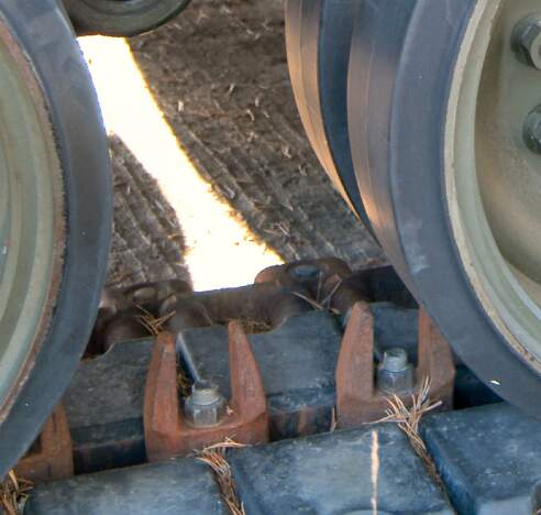
Reference photo used:
Single link:
Double:
3D print next and need to test the fit onto my M60 “Slick” project…
I have uploaded the T97E2 tracks for download: STL file 1/35 T97E2 track links for M48A3/5, M60, M103 tanks, and M88A1 ARV・3D printer design to download・Cults.
Thanks for your support.
Kind regards,
James
Based on Vodnik’s feedback, I improved the design of the T97E2 tracks significantly.
Rubber grouser chevrons’ shape was fixed to reflect the sloped vertical (not rectangular but more like a prism) shape and they became thicker:
Based on this reference photo:
The inner rubber block facing the wheels had a wrong thickness so I thickened it based on the reference photo below:
One with 20 degree bent:
Fixed single link:
Fixed double link:
Uploading the revised files onto my cults3d page soon.
Next up are T96 and T142 tracks.
Another good idea would be to put some cracks and wear marks on those tracks.
On M48s in Southeast Asia (Vietnam), the humidity heat and soft soils would’ve not put a lot of wear on those tracks, so wear would not be visible…
On the other hand; the high temperatures, low humidy and rough terrain found during the many Mideast wars, where the M48 Patton was faced; either as Jordanian or Israeli tanks), tended to put a lot of wear on the rubber, leading to cracks, and tears on the shoes.
Just an idea.
I’ll leave that work up to the modeler. ![]() Gotta move onto T96 and T142s.
Gotta move onto T96 and T142s.
Tell me when you are done, I am printing me some of these ![]()
![]()
![]()
My attempt of T96 tracks with the steel grouser continues. I am not sure if I got the end connectors right however. I used the same end connectors shown in T84 tracks for M47s but looking at the reference photos, I may be wrong. It’s really hard to tell from the grainy photos. Any experts out there?
Doubles:
Reference photos:

Fixed the T96 track end connector shape based on reference photos, thanks to @gtdeath13 .
Putting all together into 4 files to upload to my cults3d page:
Single:
Double:
With 10 degree angled center guide horns:
with 20 degree angled center guide horns:
Kind regards,
James
Test printed the tracks. They look fine but not workable… I need to make some changes… I have to admit that plastic tracks are better to work with than 3D printed or cast resin ones. The structural tolerance and ease of gluing are just not there.
Then some usual jerry can holders and jerry cans:
OK, over at FB world, someone confirmed that T96s used the T97 type end connectors.
At the same time, there are early type straight oval end connectors for M48s, which I need to CAD separately:
Any thoughts on these?
Going back to the drawing board.
Will be revising this design for my personal use.
“M153 CROWS (untextured)” (M153 CROWS (untextured) - Download Free 3D model by Krisdian Hristov (@krisdianhristov) [7e3e771] - Sketchfab) by Krisdian Hristov is licensed under Creative Commons Attribution (CC BY 4.0 Deed | Attribution 4.0 International | Creative Commons):
T96 track CAD revised with the accurate end connectors (newer type):
Also added an STL file for the end connectors only for both T96 and T97E2 tracks on my cults3d page:
T97E2 track CADs also resized for better workability.
For your inspiration, here is my approximation to a T136 track for a 1/16 Paladin. The track shoes are 3D printed. The connectors CNC-milled from polystyrene sheet. The bars are steel wires 1mm diameter. The tracks that are built in this way turned out to be workable. Since I’m a lazy painter, track pads (not shown) were made separately from polystyrene sheet.
The grid in the background is 1x1 cm.
I’m looking forward to your next post.
Good luck with designing.
Your T136 track looks good. One issue though. It is the wrong track for an M109A6 Paladin.
The M109A6 version upgraded to T154 track. The face looks the same, but the guide tooth is now offset, as opposed to in the center of the track back. They should be easy to fix in CAD.
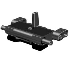
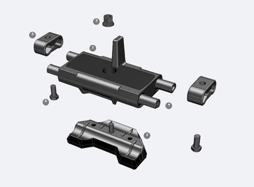
Thanks for the reference photos but I currently do not plan to CAD T136 tracks.
M60 experts, I’m about to CAD this “fin” looking parts on M60 tank series lower hull (they’re completely missing from Academy, Dragon, and Tamiya offerings) but the newer AFV Club and Takom kits give you them.
What are they called and what are their functions? Some sort of wheel bump stop?
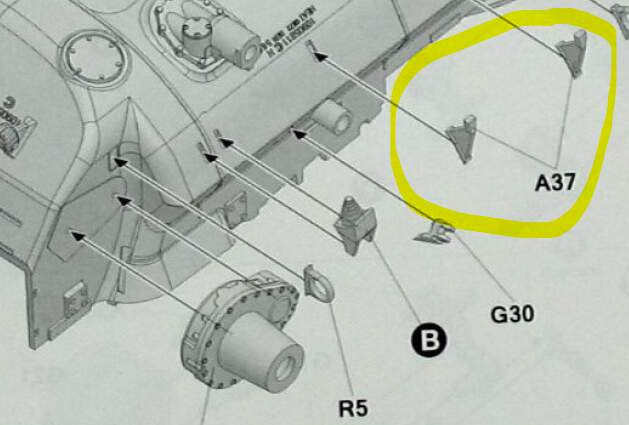
Thanks in advance.