5"38 Cutaway Turret Complex; CAD and 3D Printed

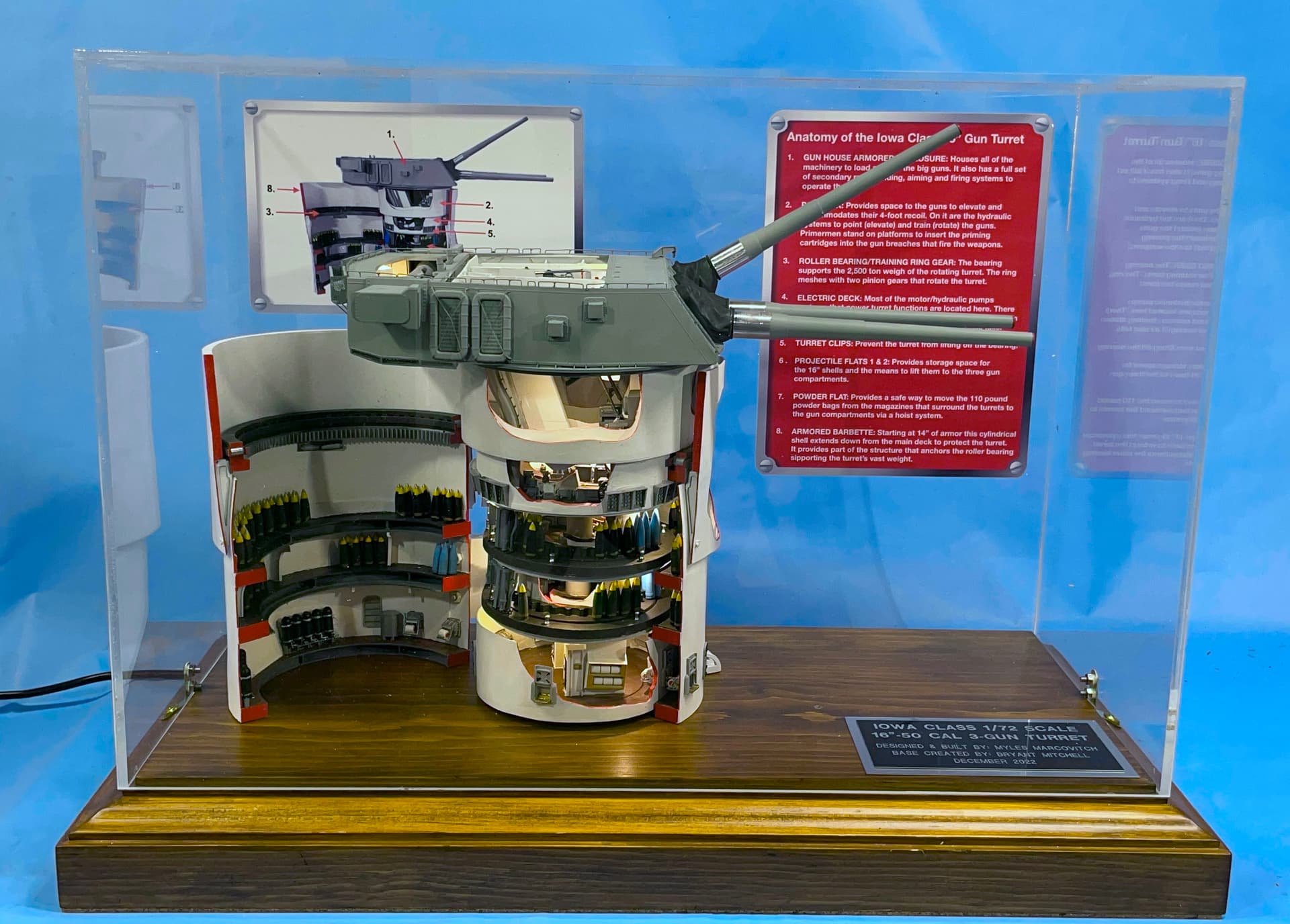
After the success of building the 1/72 scale 16" Turret from Keel to Gunhouse, the Battleship New Jersey Museum and Memorial has agreed to permanently display a similar rendition of the 5"38 Mark 28 Twin-Gun, Multipurpose Gun found on almost every WW2 (and later) ship.

To refresh your memory, here’s the 16" project as presented to the ship.

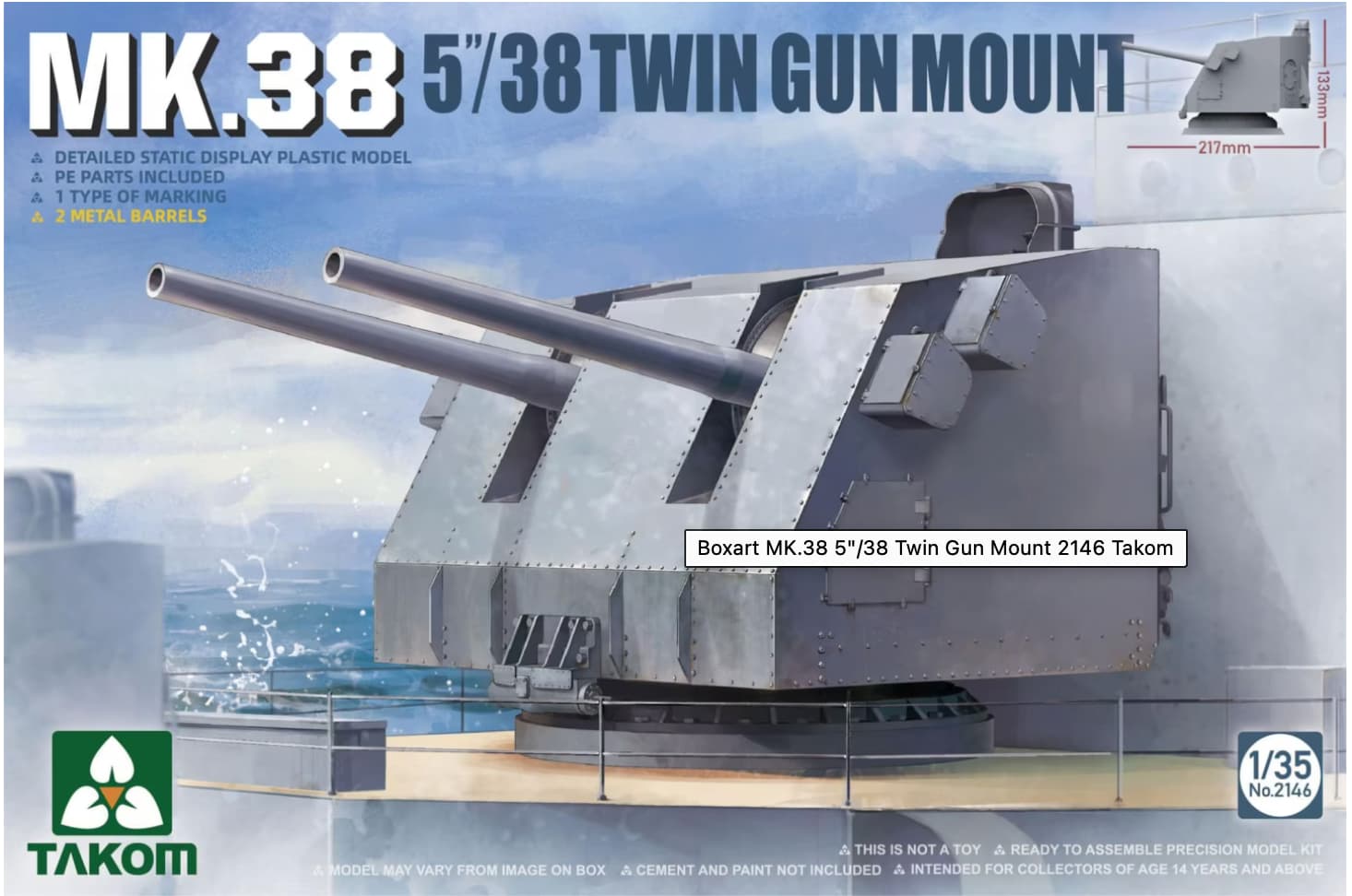
When Takom came out with the 1/35 kit of the 5" Twin turret I thought just maybe doing it again.

I contacted Ryan Syzmanski, the Big J’s curator, and asked if he would like to have a companion to the 16" turret now on permanent display in the Ship’s ward room. He immediately responded that it would be a good addition.

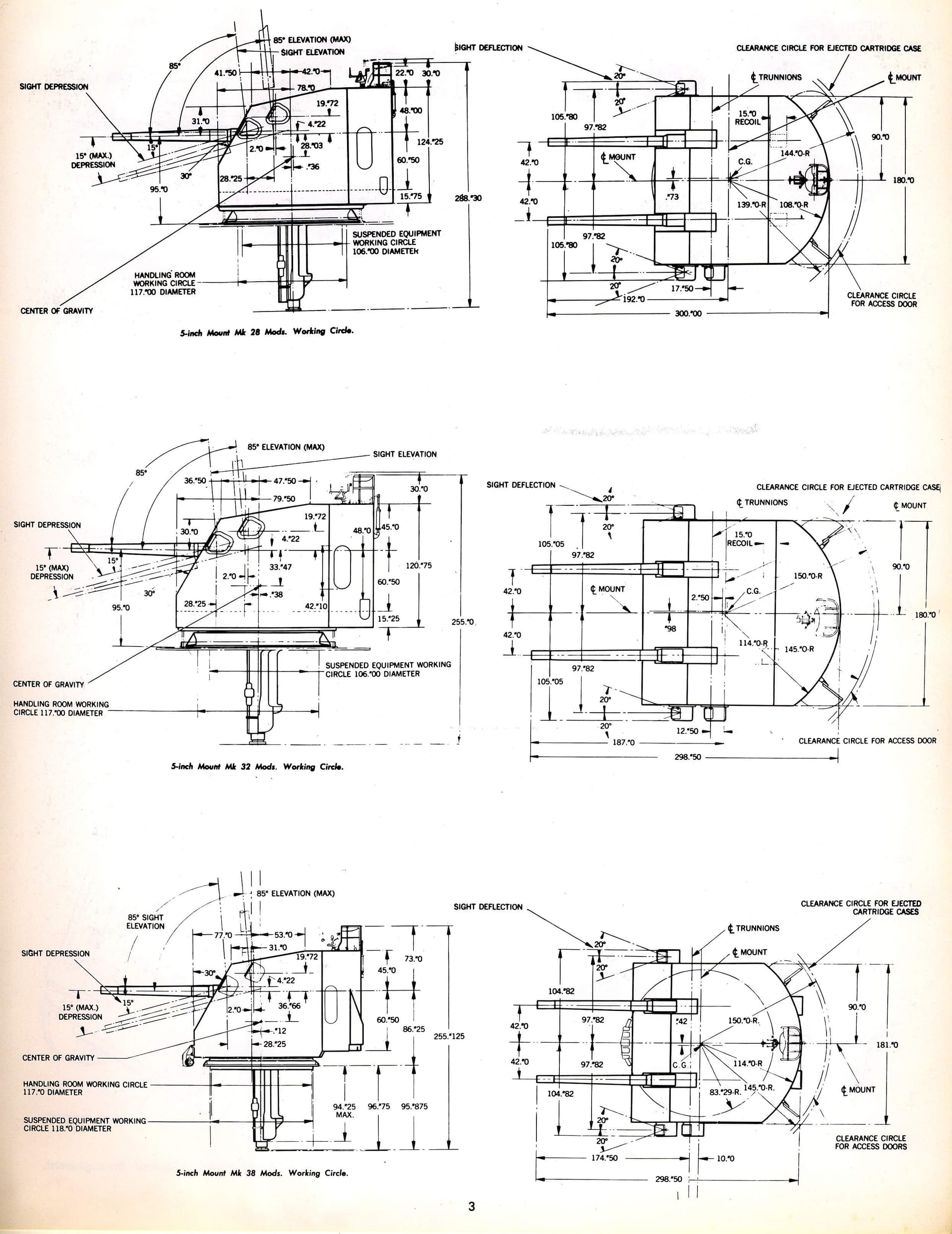
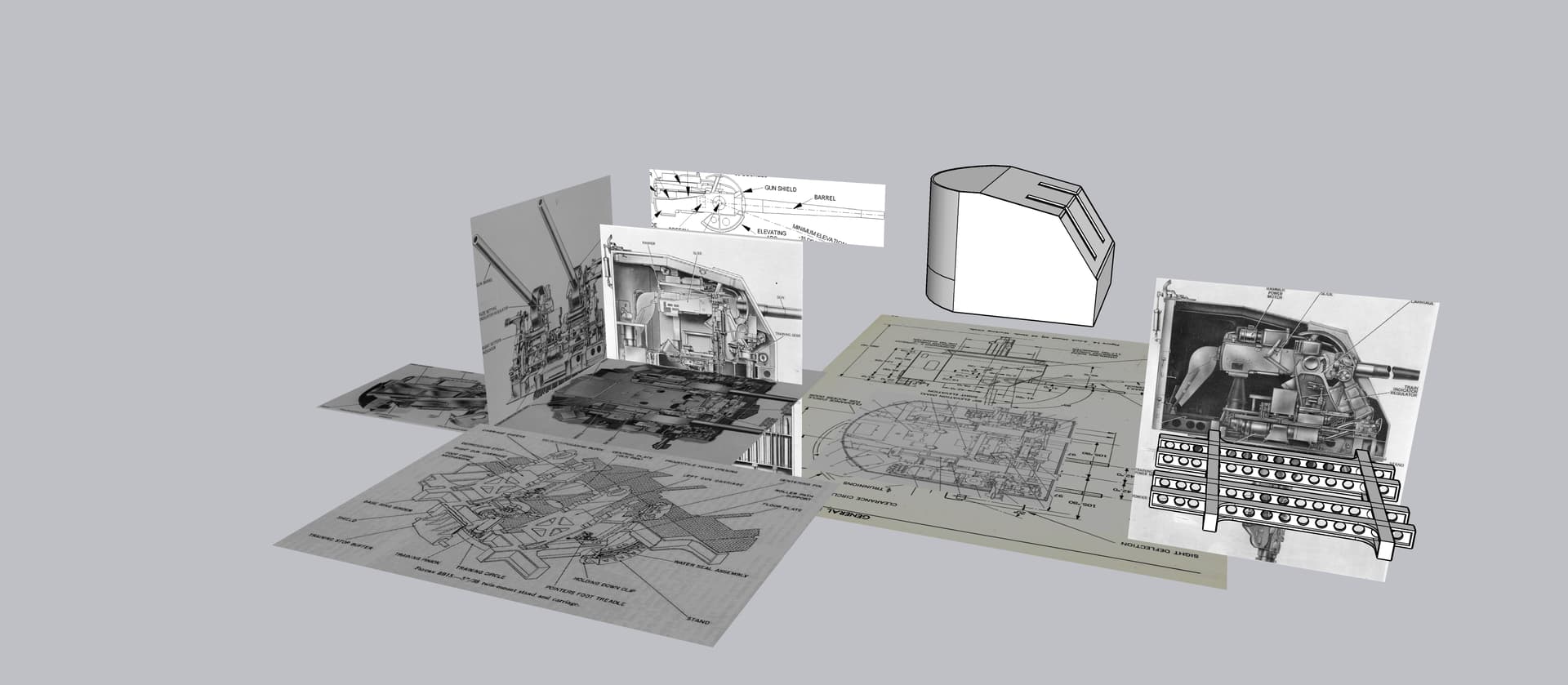
I’d been collecting reference information about the twin turrets (and the 40mm quads) for years along with my 16" research, but this past week got into full swing. That includes reading the entire service manual of the turret. Service manuals give you some line drawings that are exceptional value.

I had a lot of lessons learned with the 16" project and hope to apply them on this build. I’ve also had in the back of my mind that other muesum ships may want similar models. As far as I know, no one had ever created an Iowa turret complex like the one I built and have similar thoughts about the 5"38s based on my internet searches.

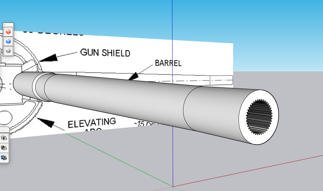
One of the first things I learned is don’t get too far into the design until you have the model in hand. I had a terrible time getting the main gun alignment with the Iowa turret since it was dependent on the openings in the front face of the plastic gun house regardless of what the plans showed. The Takom kit comes with the metal barrels included so I won’t have to special order that.

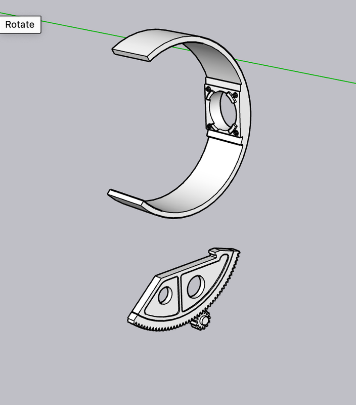
I imported relevant drawings into SketchUp 2023 and scaled them based on the actual sizes given on the one drawing that shows some critical dimensions. With that I could be secure in the knowledge that all the drawings were agreeing with each other. As with the Iowa, most of the drawings had no dimensions so it was all about good estimating.

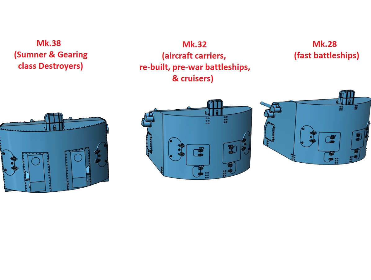
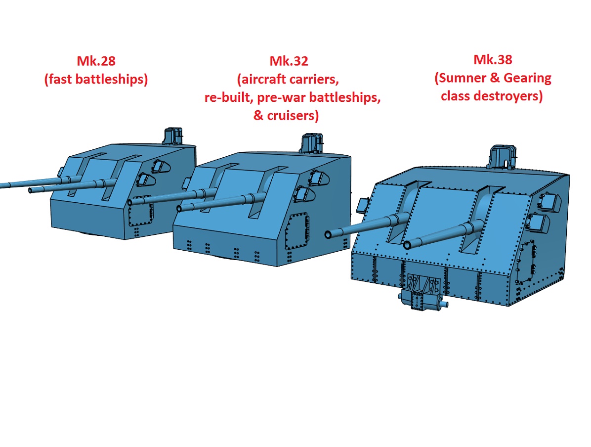
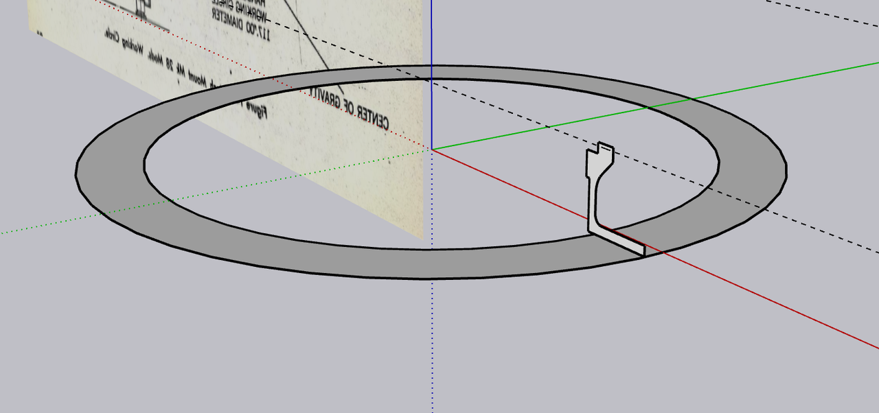
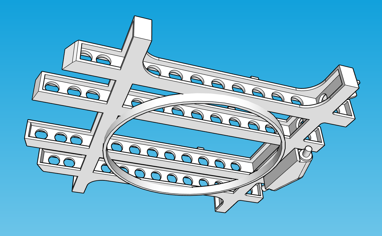
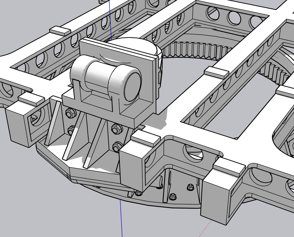
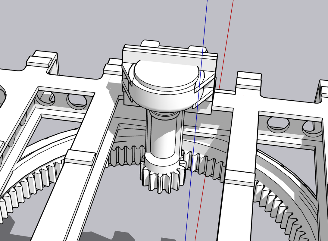
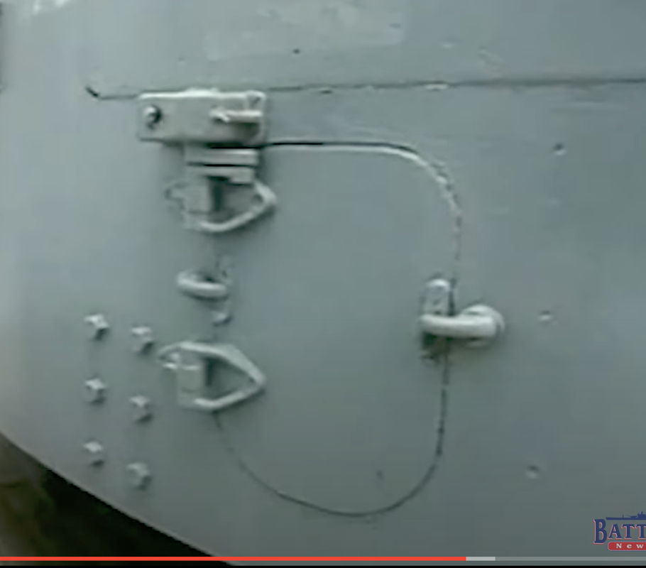
I’ve already done too much desiging the subframe that supports the two pairs of gun mounts. For example: Just looking at the box art I see that the training buffer (device to stop rotation before the turret hits something it shouldn’t) is already attached to the exterior of the turret. I don’t see that detail like that on the battleship turrets. So I have to do more research. While the guns were essentially the same in all of its applications, there were slight differences. I’m doing the battleship version. Another example is the base ring. I can tell already that the box art is not a battlehsip application.

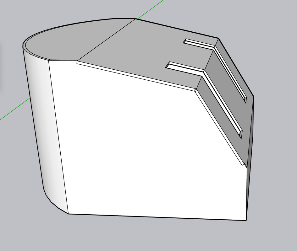
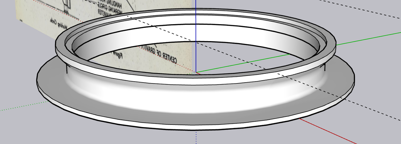
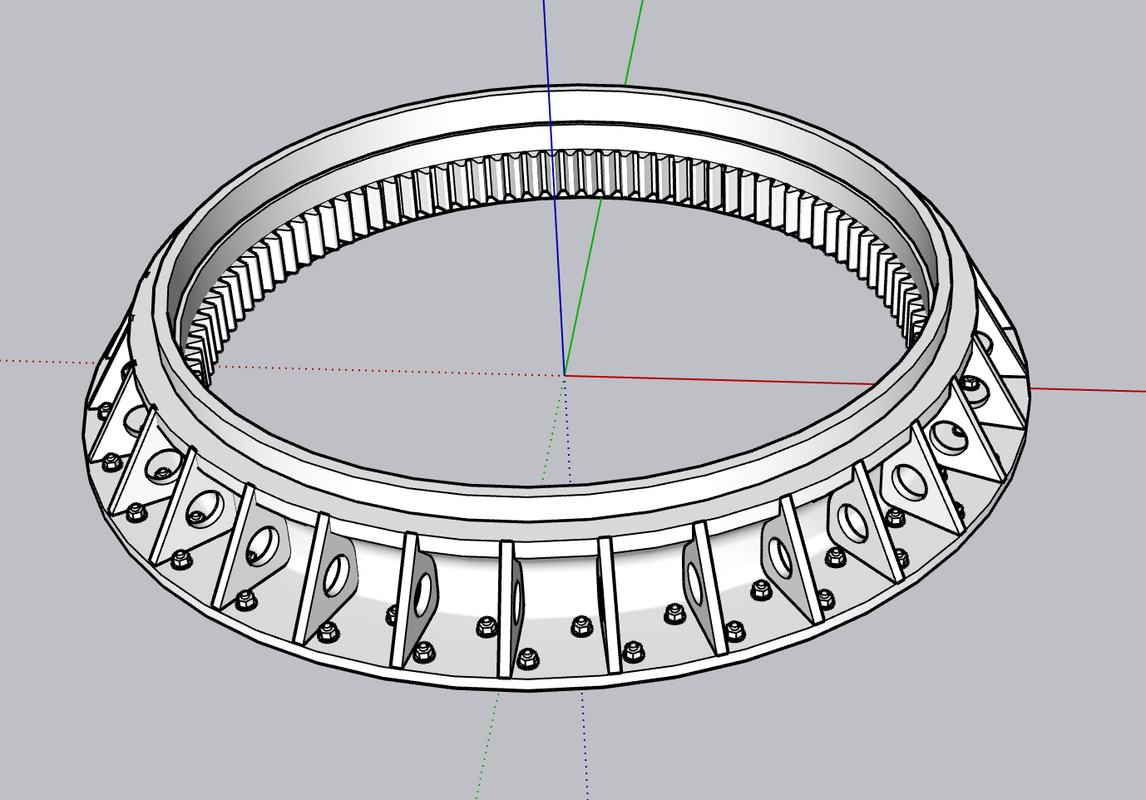
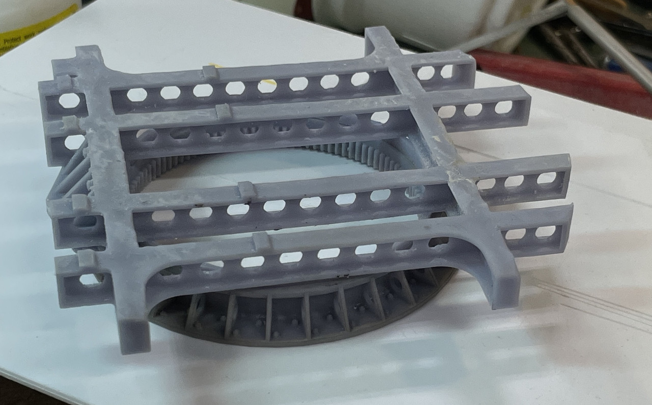
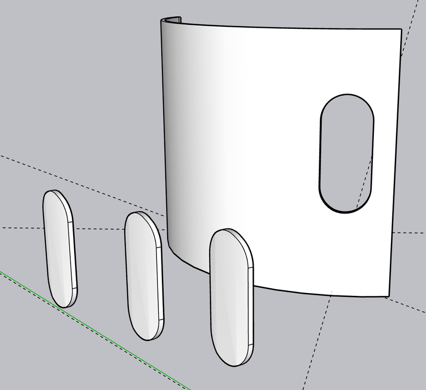
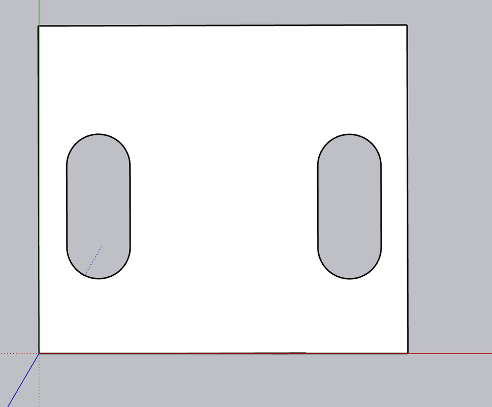
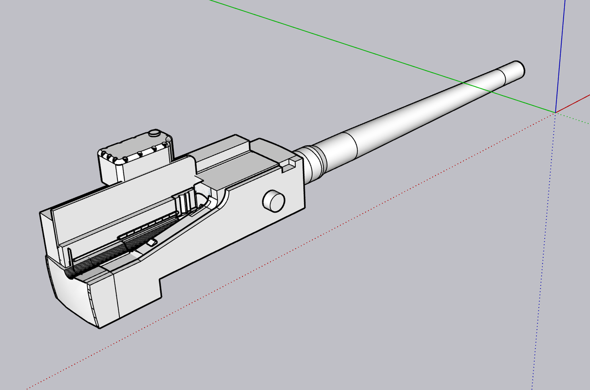
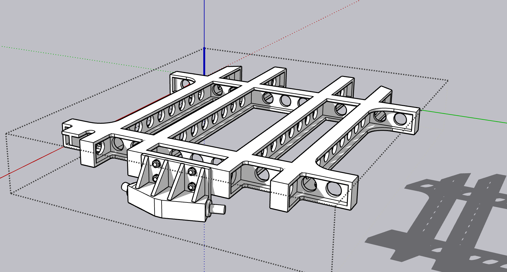
While my drawings show pretty good renditions of the floor plans of the turret, I have no idea how this relates to the Takom model. My main reason for doing the drawing was to ensure that my 3D printer could produce it in a single part. I just fits.

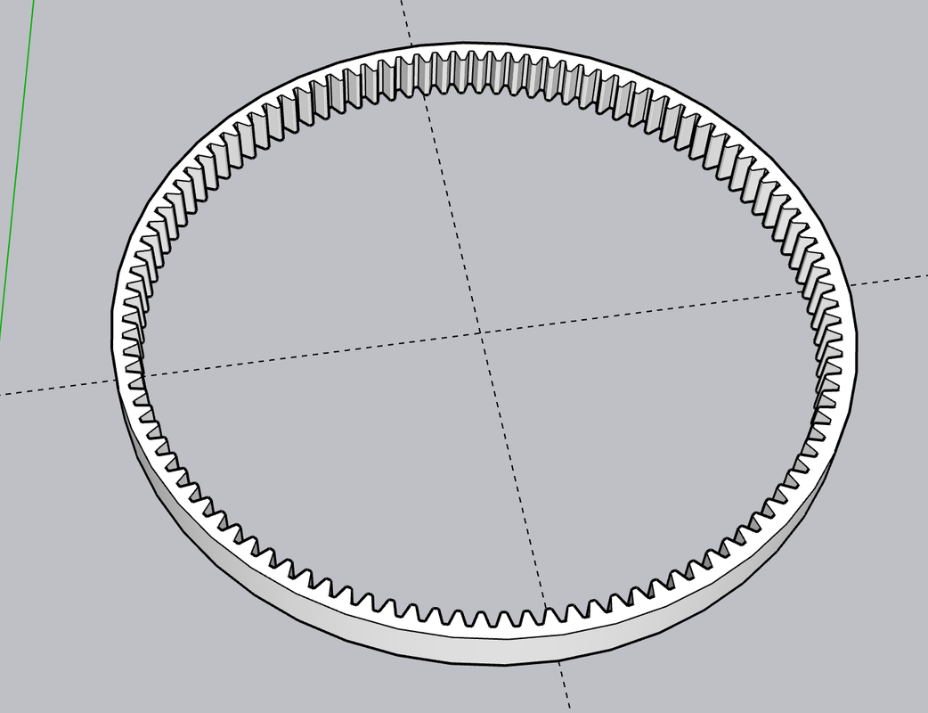
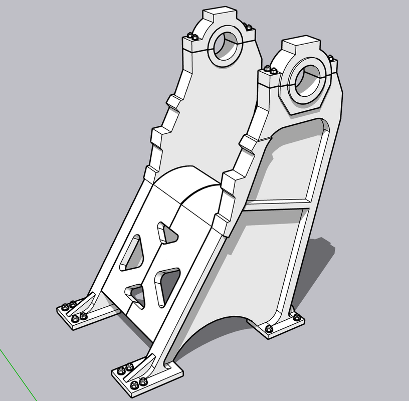
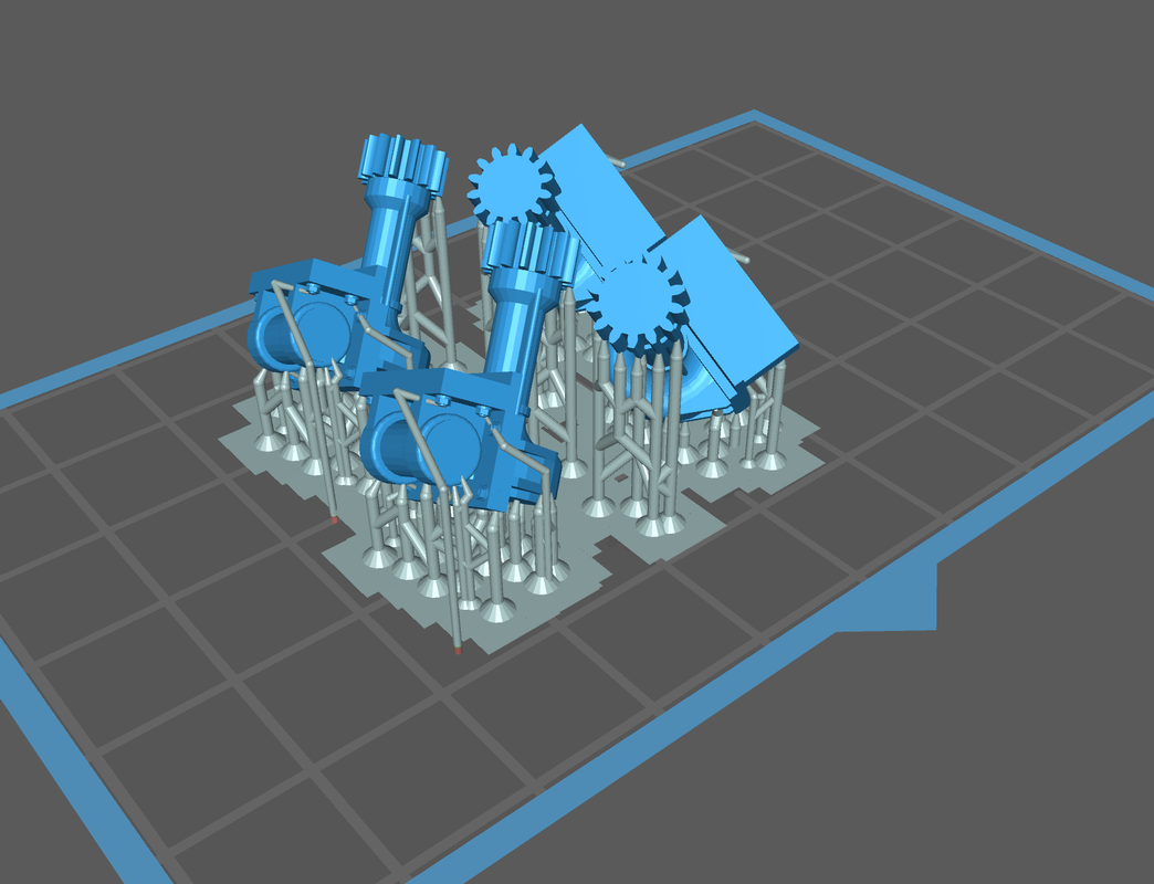
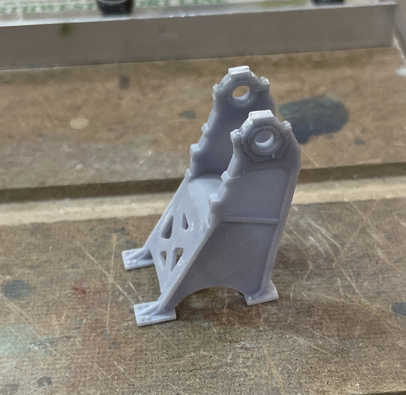
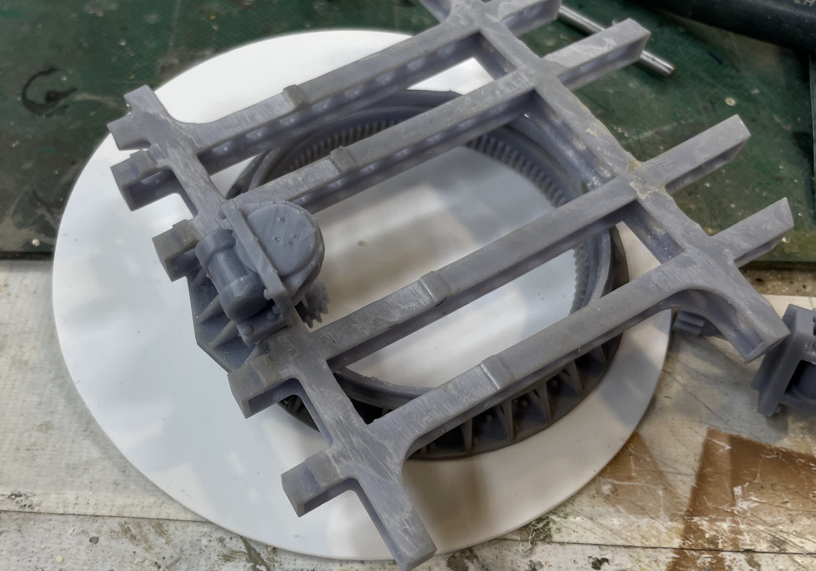
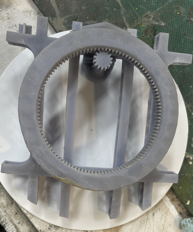
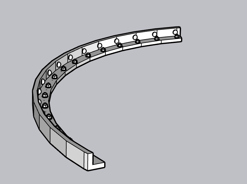
This is the subframe.

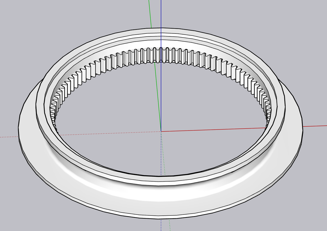
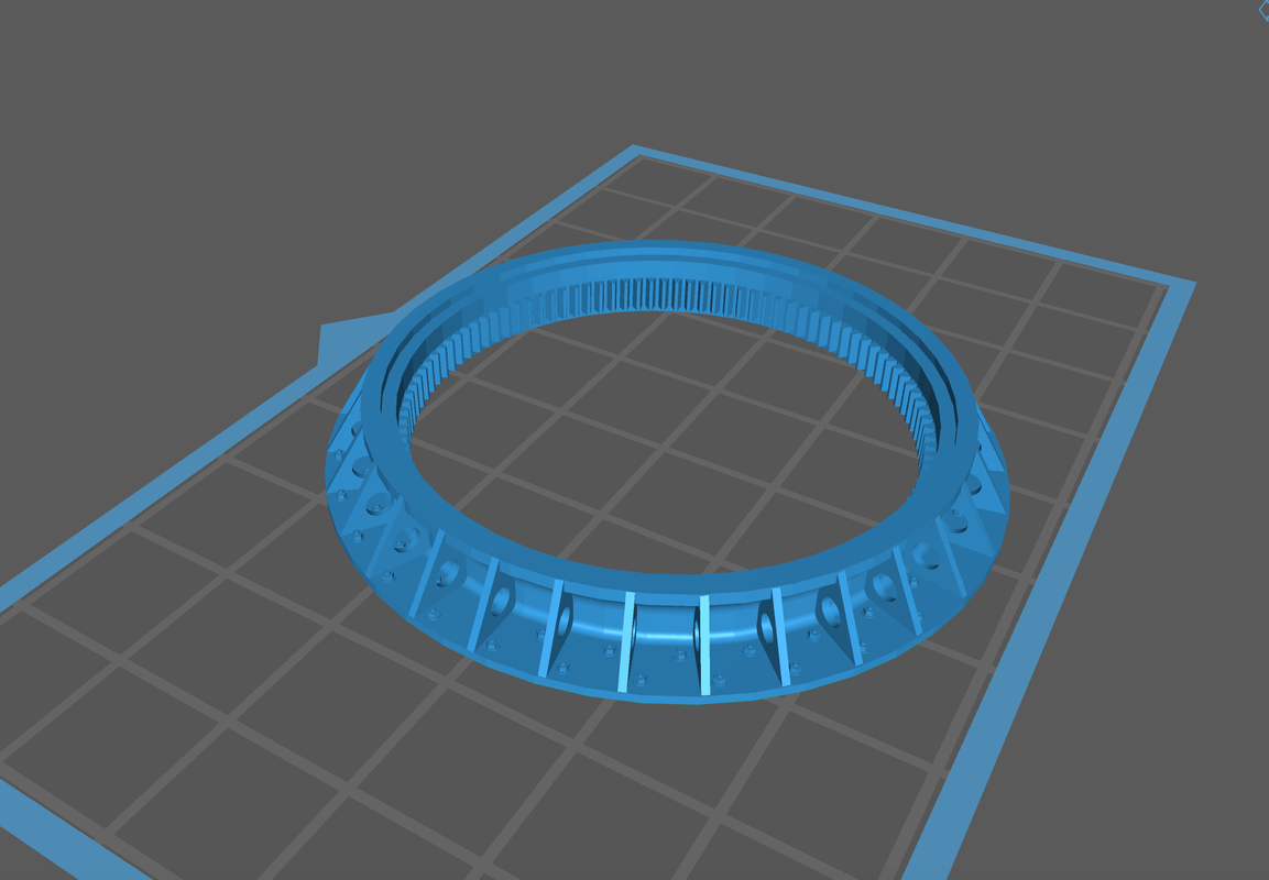
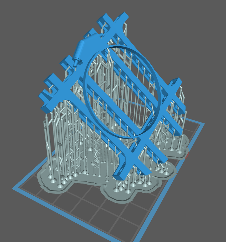
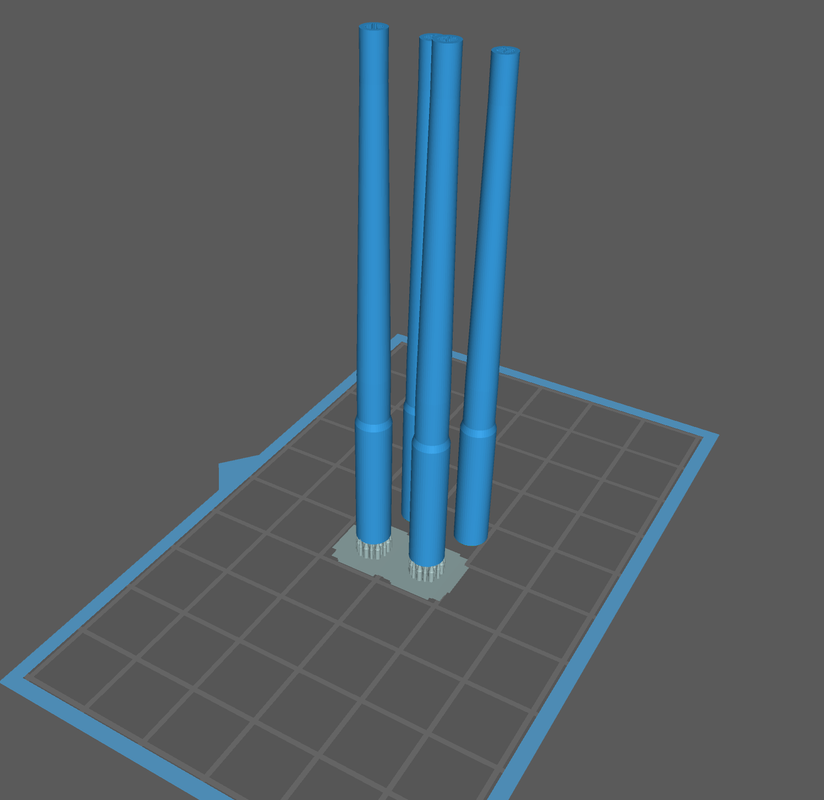
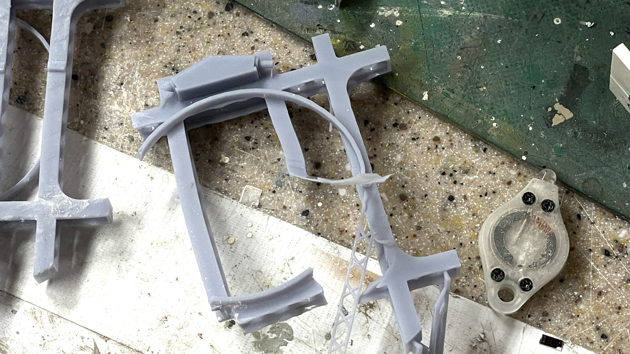
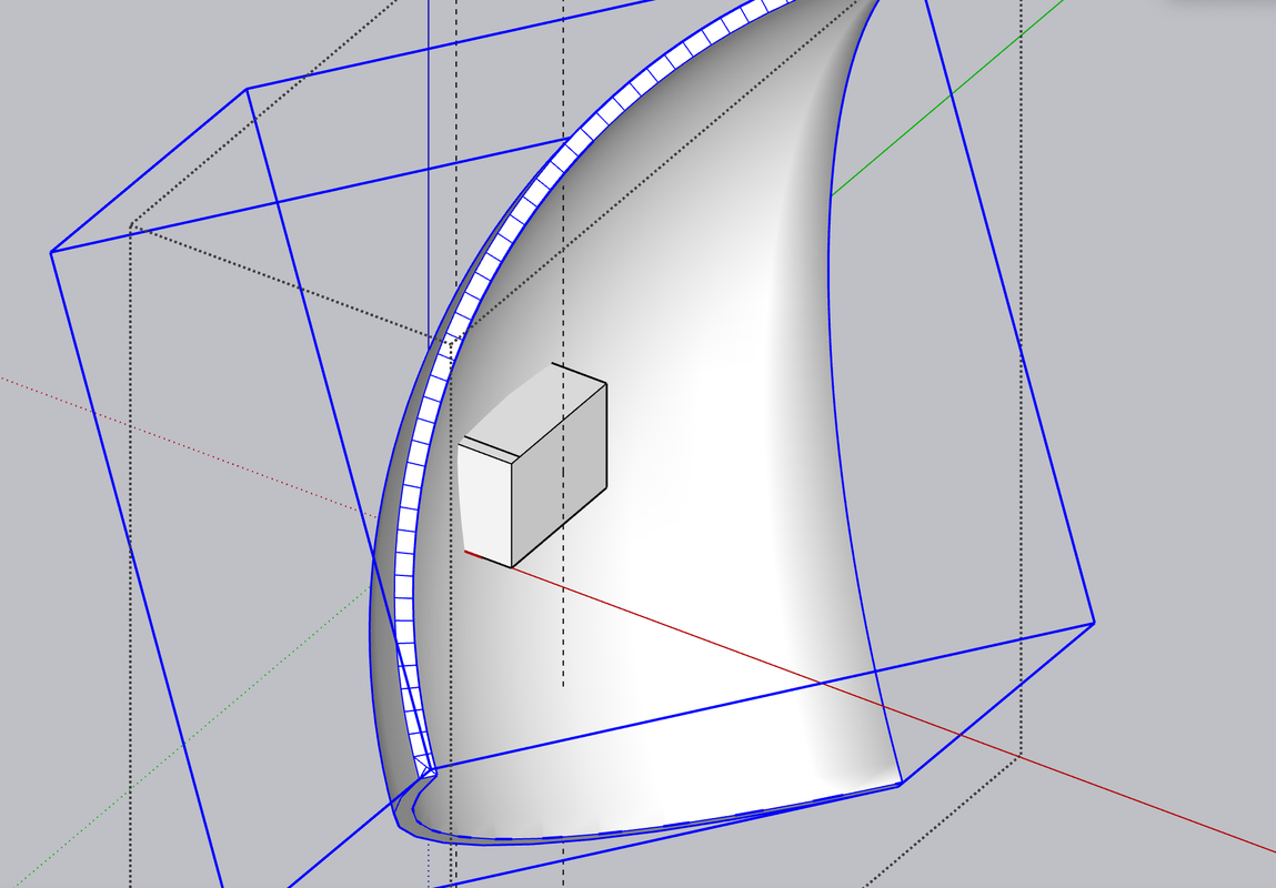
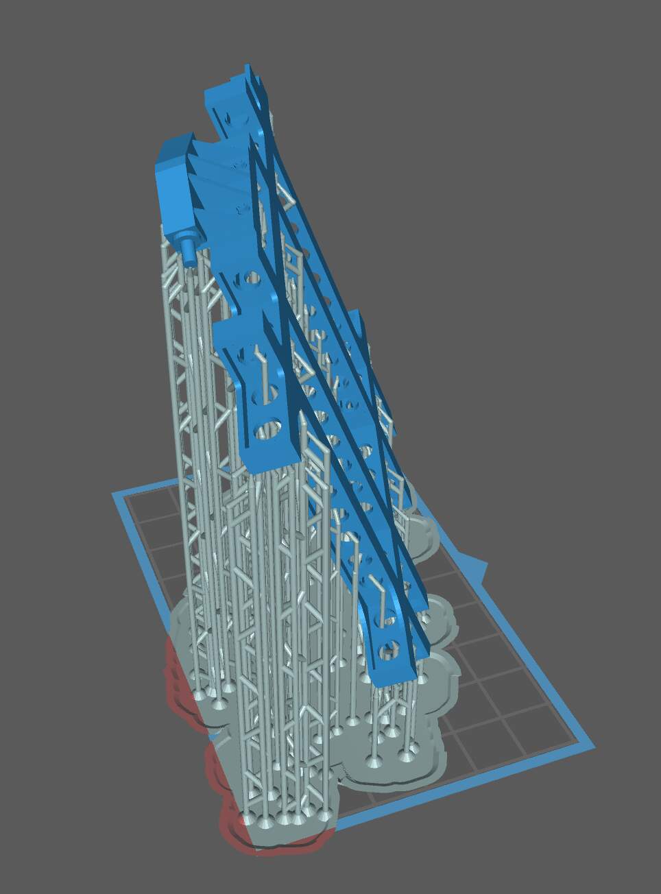
And he it is tentatively put on the 3D printer slice (ChiTuBox). I am not printing this! I don’t know if it’s correct or not until I get the model. My LHS has ordered another kit since he sold his last one.

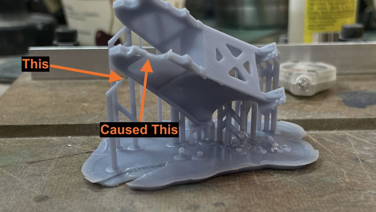
Here’s the test piece on the slicer. The red areas are out of the print range, but are just small parts of the raft that won’t matter. That said, every other angle to which I rotate the object puts some part of the actual part out of the print range. So it JUST FITS. Convenient!

I have the Takom Apache to build so this project may or may not get started first. Depends on when I receive the Takom 5" turret model. I’ll start the Apache and put it aside when the turret arrives. Building for the battleship takes precedent over models for my own collection.

20 Likes

Looking forward to this Myles … I love an encore!

1 Like

Look forward to this project. The model wasn’t a hard build. I want to repaint mine since I messed up the custom decals. Aboard the USS NC, I found the turret to very spacious except for the individual crew stations which were very cramped for me.

2 Likes

Lots of places in these turrets were for very skinny, and not-too-tall sailors in their late teens and early 20s. The sighting stations and auxiliary control stations on the Iowa turrets were ridiculous. Not only were they confining and enclosed, you had to be very agile just to reach them. As I pointed out in my turret build thread, getting to the forward sight setters station on the port and startboard positions required stooping under two sighting telescopes into the bowels of the turret side compartments. As a visitor looking into the space I found it daunting at best, and impossible in the least.

I noted that I’ve read the manuals for the turret. The mechanical ingenuity on display is mind boggling to me. For example: instead of the optical sights moving with the guns as they elevate, only the prisms inside the scope assembly change. Furthermore, the prisms on the trainer’s and pointer’s scopes had to be synchronized precisely. Added to this was adjusting for trajectory of the shells fall versus line-of-sight to the target due to gravity and earth curvature, coupled with the right hand drift of the shot due to the action of spin induced by rifling. Add to this is the lead angle due to the relative motions of the ship and the target, made the gun directors’ role very complex indeed.

It also explained the role of the sight setter. I never understood what they did in the 16" turret until reading more about it in the 5" turret. The trainer and pointer don’t make these prismatic changes. It’s the sight setter’s job. He receives the input commands from the plotting room or gun director as noted on two dials, that he matches with corresponding numbers on his dials. His adjustments are translated to the prisms in both telescopes. This is a constantly changing number depending on target and firing conditions. Then through a complicated arrangement of shafts and gears these tiny measurements result in the micromotions of the prisms. While this is also done on single gun mounts, it’s that much more complicated with the twin turrets.

Another ingenuity example is creating a means to adjust the time fuses in the nose of the antiaircraft ammo while the shells are in motion on the shell hoist. In the open turret, like those found on the sponsons of the Essex Class carriers, the fuze setting was manually done on a piece of apparatus on the gun’s platform. But in the twin turrets that were effectively a semi-automatic firing system, the fuze setting had to occur concurrently with other activities. The firing rate of the twin was up to 22 rounds a minute. That’s a round every three seconds. This could only be accomplished with fuze setting being completed automatically.

Like the prism settings, the fuze settings were sent down from plot or gun directors. These values were translated into a series of rotational degrees that correspond to the rotation of the fuze head. The shells was transported from the magazine separately from the powder cartridge. They were mated in the ramming phase on the gun itself. The powder hoist was a continuous chain with cups that held the shell nose down. The cup base engaged pins on the shell nose, rotating it and setting the fuze. The fuze setter had it’s own chain that ran parallel to the lifting chain. This chain engage with it a gear train that rotated the cup. The setting chain could move independently in relation to the lifting chain so it can rotate the fuze in either direction depending on position.

Both the shells and powder cartridge are hand loaded from the magazine to the handling room, and then hand-transferred from their respective lifts to the powder and projectile hoists that go to the gun room. In the gun room they area again hand-transferred to the loading trays on the gun slides. From that point, the gun fires in automatic mode. The breach opens, the shell and powder are rammed, the breach closes, gun fires, recoil action opens breach, ejects spent cartridge and resets everything for next load.

The limiting factor is the human’s ability to move all that ammunition from place to place. In practice, usual firing rate was around 15 per minute. They could reach bursts of up to 22, but it was exhausting. It also explains why all ships with these guns (lots of ships) had loading practice machines. Since the guns were basically automatic, loading was the only manual operation that required terrific coordination between all parties. This required practice, practice, practice! The warhead weighed 54 pounds and the powder cartridge was 29. Imagine slinging those things around in battle conditions, and it might have been in rough seas! None of these gunnery jobs were for the faint hearted, whether you’re talking about big guns, medium or small ones.

BTW: I did find a wonder rendition of a single 5"28 caliber gun. It was on Cults for $40 as a set of STL files. I thought seriously about getting it to give me a head start on drawing the gun house portion of the project. However, upon close inspection, there are enough variations and mods that I would need to make that it may not prove worth it. Making changes to STLs on SU is not easy. It’s often easier to draw something from scratch time-wise than to try and fix something. I have good references for the gun design and will give it a go. I can always order the STLs if I run into a jam.

5 Likes

The M1 heat round is 54 lbs and sabot round even heavier. I think my fastest loading time was 3.5-4 secs, passing was 7 secs. We didn’t have stock pile they did so hats off to them for that rate of fire. We did practice a lot.

1 Like

Great subject, Myles!

Really looking forward to seeing the magic you do.

Be advised that the Takom kit is a of Mk.38 which was a lightweight version fit to Sumner and Gearing class destroyers (bottom two images of the drawing below). New Jersey was fit with heavyweight Mk.28 mounts having a larger gunhouse with a slightly different shape (top two images in the drawing below). The armored rangefinder hoods are bit differently shaped, too, as are the spent shell ejector ports and housings on the rear wall. I’ve included a couple of renderings here to help show some of their differences.


Probably not a problem for a man of your talent and skills.

Have popcorn in hand!

6 Likes

Thanks for that heads up!

I kind of suspected that. The first thing I noticed was the traverse buffer was external to the gun house on the model and the drawings I have (and what I was doing on the first pass of the subframe) is internal. I also noticed a signifcant difference in the mount. The ribbed casting is not visible on the BB versions and there is a weather seal surrounding the base hiding any details. The BB’s are welded without all the fasteners showing. I will probably have to scratch-build some components of the gun house to make it worse, especially the back with the difference cartridge discharge doors. Removing details is much easier than adding them.

4 Likes

Newsflash!

When my LHS told me the Takom model was in, I went to pick it up, only to find that they had ordered the 16" turret. We all know how that turned out. And… the 5" turret is out of stock…EVERYWHERE! So what to do? Since I’ve already told the ship I’m building this, I feel committed. So now I’ve decided to scratch-build the entire thing. All that this requires is the gun house shell, the ring base, Officer’s cupola and the guns themselves. It’s the guns that I’m missing most since they were metal turned barrels included in the kit.

As I noted, the kit’s based on the Mark 38 destroyer version, not the Mark 28 Iowa-class version. That would have required some kitbashing. Now I’m no longer constrained by the kit’s inaccuracies or it’s scale. I can choose whatever scale I want. I could find a machine shop in town that could do the barrels for me, or I could 3D print them. Since that will cost be basically nothing, I will go that route first. If it doesn’t work, I can go to plan B with a machined barrel. Since the kit included these parts, I suspect finding the barrels themselves on the aftermarket will be difficult.

My little Taig lathe could turn the barrels, but it’s not really suited to turn long tapers. Ideally, the barrels should be produced on a Swiss-type screw machine that are designed to produce long, slender objects.

So the game is afoot.

I als need to get some diamond plate for the gun house flooring panels. Even this could be 3D printed depending on the scale I choose.

Stay tuned… this could be a little rough.

8 Likes

Maybe someone has the kit but is not married to it yet and might sell it to you?

2 Likes

1001 Hobbies has it in stock as of this posting.

2 Likes

Looks like they do, but I think I’ve crossed the Rubicon. I’m going to scratch-build it in 1:48. There’s a lot of aftermarket things in that scale that I can use such as diamond plate sheet for the deck plating and drop foot rungs that run up the sides all over the place. It’s also a scale that fits neatly on my printer and big enough to load it up with details. I found an exceptional reference manual that is totally comprehensive with every detail of every version of the turret. Turns out that the ones on the big ships had 2" armor plating which is exactly 0.040" sheet in 1:48. Convenient! It also contained enough details about the elusive projectile and powder hoist machines to maybe preclude needing to make a field trip. When I get further in the weeds I’ll be able to figure out if I need to do any 1:1 scans.

I will also decide if the kit is still a reguirement. I would really like metal gun barrels.

https://maritime.org/doc/fiveinchtwin/index.php#toc

I am still blown away by the level of hydraulic and mechanical sophistication exhibited in the design of these complex “machines”. My Power Technology professor at Michigan State U was a Chief Engineer in the Naval Reserve. We went heavily into hydraulics about which he was very knowledgeable. I now know why. Every weapon system he touched was jam packed with them. He also was a wonderful man. He served on a number of capital ships. This was 1966 so WW2 wasn’t that long ago.

4 Likes

With my decision to go cold turkey and do it all from sratch, design work has begun in earnest. While I don’t have fully dimensioned drawings for everything, I found another manual that fully details every aspect of the twin turrets and gave me enough specifics about the Mark 28 so I can get many important things right. As a result, I have fully TYdrawn to exact specifications the armored gun house.

The Mark 28’s armor thickness was 2". That’s 0.040" in 1:48, so using that sheet thickness, not only is very workable, but is correct scale thickness. I didn’t have the luxury with the big gun. In 1:72, the 1" wall partitions would have been 0.010" sheet which is too thin to be practical. On the Mark 28, the armor plates are attached to internal angle braces by countersunk bolts and rivets. I was incorrect earlier when I said it was welded. There are a few exposed bolts where the floor framing members tie into the walls. Also I’m striking out finding pre-made 14" drop rungs wirh bolt rings. I already printed them for the big gun and can use the same drawing scaled up to make them for this one. I they held together at 1:72, they’ll do well at 1:48.

I have actual diameter measures of the base ring and training gear so I chose to start here. I also have a section drawing across the ring which I scaled. I placed the profile on a ring that corresponded to the base’s overall shape.

Using the “FOLLOW ME” tool (select the ring, select FOLLOW ME and then select the profile) and the program magically lathes the profile around the circumference. The counterbore and the land represent the lateral and tapered roller bearings on which the rotating mass revolves. I’m not going to detail the bearing. Unlike the monsters in the big gun, these would be almost indistinguishable in 1:48.

I learned how to do internal ring gears in building the big gun, but I’ll quickly review it. I have an add-in to make volute gears. You enter the number of teeth, the pressure angle, and the pitch circle radius and Voila!, it draws a gear as a separate item. It only draws external pinion gears, not internal ring gears. I was able to find the exact number of teeth and the pitch circle diameter of the Mark 28’s, and with those numbers drew the external gear. I also had the outside diameter of the gear which was the inside diameter of the bottom counterbore. I centered the external gear over a filled circle of the outer diameter and INTERSECTED the faces. I now had a drawing of a filled circle with line drawing of the internal teeth inscribed on it. I delected the inside, and then PUSH-PULLED the remainder to the height of the full gear as shown on my scaled cutaway drawings. All in all it took as long to do it as to write this paragraph.

I inserted the completed gear into the base ring.

The last things to do was add the reinforcing ribs and the nut/bolt/washer N/B/W images on the ring flange. I made one rib based on profile drawings and counted the number on the prototype. Looked like there we 32 of them. In SU, you use the rotation tool, with the center placed in the ring’s center. You move/copy a single rib 11.2 degrees corresponding to the gap between them, and then key *31, the program copies the rest equally around the ring. It’s “31” not “32” because you’ve already copied one.

I did the same thing with the N/B/Ws making a set of two and copying them around the ring.

Because the geometry is so regular and one dimensional, I am going to attmpt print the entire part directly on the build plate. It will all depend on the build plate’s ability to hold onto the part during the formation of the base perimeter layers which have the greatest amount of surface area. I those layers stay put, the rest of the print will be no problem. I will only take about 20 minutes to print, so I won’t have long to wait.

If I was printing this part in 1/35 instead of 1/48, it would not fit this way and would have to tilted. Without tilting, there are no supports to deal with and details come out perfectly.

With accurate overall gun house enclosure dimensions and wall thicknesses, I was able to adjust my frame drawing so it was exact. If I was using the kit, I would have to wait until I could meassure it directly before finalizing the frame. I also had the exact diameter of the ring that connects the rotating to the fixed structure and attached it to the frame. I moved the training buffer inboard of the frame extremis to conform to the Mark 28 configuration.

Again, in 1:48, this fits the printer nicely and will be a single part. This ensures perfect alignment of this important structure.

Last part I detailed was another critical one; the guns. I had good profile drawings so I was able to create the correct straight and tapered portions. I added some rifling. There are 40 lands, but did not add any twist. You’re only going to visualize the very outer edges of it. The outer lip of the muzzle is rounded. I will do this as a post-print operation.

I’m trying two print schemes: Directly on the build plate and raised off. Since it’s so symetrical, it can be printed straight up with no overhangs or islands. While it should print directly, I’m thinking that raising it will facilitate liquid resin draining from the bore.

We’ll see which one wins. Unlike the ring gear which had little height, the guns will take over 6 hours to print. In LCD resin printing height is the key varialble in print time.

I found excellent elevation views of the all-important gun mount castings and will tackle them next. Also found good information about the complicated projectile hoists.

I actually need more information about the floor plan of the projectile handling room and the powder and projectile magazines on the 3rd deck.

5 Likes

I’ve started producing parts with varying success. My first part was the base ring printed flat on the build plate. For some reason, the training gear teeth started to form and then just stopped. A few layers were laid down nice and parallel, but then nothing. I also had some slight delamination. The delamination I could fix, but the gear teeth would be a bit trickier. I could print the gear separately flat on the plate and insert it. Meanwhile, I’ve set it up at an angle and will try again before going with the separate gear approach.

Next print was the main frame. Strangely, one set of supports failed causing one of the frame’s lower extensions to fail. I changed the supports in the slicer and tried again. Here’s attempt #1 compared to attempt #2 which was clearly worse.

There’s a silver lining. The arm extensions are mirror images of each other. By surgically removing the bad arm from #1, I was able to graft the good arm from #2. With some thick CA followed by Bondic UV resin, the graft is invisible and strong. The Bondic is the same chemistry as the UV printing resin and when applied to UV parts welds them. Only caveat is the UV curing light must be able to reach the Bondic so it can be used on blind glue joints. Otherwise, it’s essential in your UV printing tool box. It cures in seconds!

Here’s the removal of the bad arm.

Here’s the part ready for the graft. I broke apart #2 to better expose the arm for amputation. I then trimmed the end properly in a miter box with razor saw so the end was square.

I used the CA to stabilize the part (with accelerator) and then used the Bondic to fill all the gaps.

And after sanding, the part, when painted will show no evidence of being “Frankensteined”… Just made a new verb.

Here are the remains of #2. It served well and saved me a bunch of resin. Resin is not cheap, about $40 a liter. I never throw away rejects and have used them many times to provide repair pieces. I’m creating two boxes… “good parts” and “bad parts”. Often it’s about 3:1 bad to good. 3D printing is an art with a scientific underpinning. I thought I had figured out the failure mode on #2, but the results were worse. The failure still started in the same region some something was going on there. Since I now have a good part, I’m not going to worry about it any longer.

Right now the guns are on the printer and will come off around 7:00 tonight. The fit of the frame ring into the base was very tight. I may have to chain that diameter on the recess a tad so it slips in. They were both created by the same circle so their diameters are exactly the same on the drawing. However, the printing process enlarges parts very slightly, so the holes gets smaller and the ring bigger by a few thousandths each. What was a slip fit is now a no-fit. It’s the reverse with laser cutting. I you cut a window opening and the window frame with the same dimension. The opening grows bigger and the frame smaller since the laser cutting beam has some kerf width, just like any saw only much tinier.

I almost have the gun mounts ready for printing. I drew them over my profile drawing. My first attempt had the cross bracing in the front on the wrong end. I was able to fix it without too much difficulty.

The guns are printing successfully with both setups building straight down.

I redid the ring gear for printing and drew the training worm and pinion. I ended up making the gear with 14 teeth and a pitch radius of 8". It meshed well. Nothing is going to have to move and everything is printed as a solid obect.

Here are the finished drawings of the engine mounts. I saw that there were bolts holding them down so I added those and added bolts to the Trunnion Caps (being printed as a separate item so so the guns can be installed. The bosses jutting out from the side are where all the sighting gear is attached

I did have sufficient drawing to build the training worm and pinion with reasonable fidelity. The worm is driven by a drive shaft from the hydraulics. Manual drive is selected through a series of clutches, but still enters the worm via the same shaft. I’m probably going to use metal shafting for all of them… and there are a ton.

Front view:

And reverse view:

Here’s how the training gearing is going on the printer. As usual, I never print just one. It cost about 20 cents worth of resin for each one and it doesn’t add any printing time. If this was a filament additive machine, the more parts you have up on the machine the slower it is since it must draw each line like a plotter, versus the resin machines that expose an entire layer at once, like a laser printer. I group them close together to facilitate popping them off my flexible build plate.

Guns just came off printer. I was correct. The resin didn’t drain well from the one that was printed directly on the plate and the bore is narrower at the plate end due to “elephant footing”. Elephant footing is the phenomenom created when the part widens at the first five base layers. These are generally exposed at 1 minute instead of 2.5 seconds. The long exposure is used to create the “raft” that holds the model to the build plate. You really want this layer fully hardened so it sticks well. When you put a part directly on the plate, that 1 minute exposuse/layer causes those five layers to widen also. They become wider because the long exposure leaks from the pixels that are to be illuminated to neighboring ones.

The gun with the support’s bores are parallel throughout the print. They’re in the Ultrasonic cleaner now. I will take pictures as I clean them up. I just put the modified base on the printer. It will be done around 10 p.m. Nice thing about printing… I generally like to print overnight so it’s working when I’m sleeping. Unlike string printing where you have to keep an eye on a clogged nozzle, with resin printing, when the part is right and mounted right, and the printer is lined out, it will work without any attention.

From my cursory inspection the guns show no imperfections and should look great.

3 Likes

After cleaning you can see the difference between the non-support, direct print one on the left and the one with the supports that raised it a bit off the build plate.

Besides that slight difference in the bore at the breach end, the rest of the print is perfect and not different between the two. They’re getting post-cured now and only a very little cleanup will be required to create some beautiful guns. There are no layer lines and they ARE NOT warped that I can see. I’m quite pleased. I will not have to get machined barrels.

Once they’re cured, I will take a diameter reading at the slide end and use that number to draw the bore in the slide, plus some clearance tolerance. I don’t want a press fit. If I wanted to, I could make the guns able to recoil, but I probably won’t. This will be enclosed in Plexiglass and never be touched to play with it.

Onward and upward!

5 Likes

Following along Myles to watch you work your magic on this :slightly_smiling_face:

1 Like

Hope I don’t disappoint. The guns are perfect. With a strong manifying glass (Microscope?) you can actually make out the rifling, But it’s only viewable by letting light reflect on it from the breach end of the bore. In other words, only I know it’s there.

The new base is in the Ultrasonic now and came out perfect also. All the gear teeth formed correctly and my slight easing of the mounting ring diameter let the frame ring slip in nicely.

I’ll put up images tomororw.

Right now the gun mounts are in the printer. I get them tomorrow morning.

The reprinted ring gear was excellent, one slight area needing fixing. I fixed with Bondic. It fits the mounting ring on the frame well and the two can rotate. The real one has retaining clips that grip under the training gear and I’m going to duplicate so the turret will be positionable. I found that the Training Buffer interfered with the ribs on the stand, I surgically removed the offending material. I found another drawing of the buffer and it looks like the back is relieved for the same reason.

The mod: I also replaced the printed plungers with steel. One didn’t form right and after replacing it, I did the other to match.

The gun mounts printed well. I always make more than I need and one set had a fatal defect. Didn’t matter, I had three more and only need two. As printed off the machine.

Finished set: Not glued, just set in place.

Printed a gaggle of trunnion caps. I erred. I put two bolts on each side. There is only one… Not going to worry about it.

Here’s the caps placed on the mount. Again… not glued. Can’t do that until the guns are in place.

Here’s the one that failed. And you can see why. That support failed. When the support fails it usually leads to a local or catastrophic failure depending on how strategic the support is.

I also printed successfully, three out of four Training Worm/pinion assemblies. Only need one. This one was also a support failure, but of the more catastrophic variety. It left the partially formed part stuck to the FEP film at the vat’s bottom. The new version of Elegoo’s FEP film is very forgiving. Stuck parts pop off with no damage to the film. I can run for months without having to replace the film … a 20 minute job. Looks like something that didn’t make it through the Star Trek transporter too well…

Here are the good ones. Even among these there are some that are better than others. Always make more than you need!

Here’s the trial fit top view. Part has NOT YET been finish sanded and you can see by the support marks on the top.

And the bottom view showing the pinion meshed with the training gear.

That’s all the parts that are drawn to the point of being able to print. There’s a whole lot more going on in the design department. I finished the gun shield and elevating sector gear, but both have to wait until the gun proper is finished. There are some brackets that engage in the gun that can’t be finalized until gun is done. I also started delineating the armor housing with the curved back plate. I’m going print the hatches with their hinging, but the curved wall will be 0.040" styrene. Technically, the armor on the this ship’s secondary batteries are 2.5" which is 0.050" in scale. I may laminate 0.040 and 0.010 to make fifty. Laminating also helps maintain the curvature. I had to extrapolate the lateral position of the hatchways due to the curvature of the image. I then flattened the curved piece using SU’s “UNWRAP & FLATTEN” facility.

The gear teeth are finer on the prototype, but at 1:48, if they’re too fine, you won’t see them.

Here’s some WIP shots of the rear panel. I’m not sure if the hatch is curved. It too a while to create the curve using a copy of the wall section to cut the inner and outer faces. If flat, that’s much easier to do in styren. In addition to the crew hatch, there are four others for the cartridge discharge chutes.

Here’s the wall flattened as a test.

There are angle bars that attach all of armor panels to shape the gun house. I’m going to 3d print these with fasteners. My shape isn’t exactly right as I’ve ssen on some video footage. Don’t know how anal I’m going to be about it. The fastener pattern’s probably not right also other than it’s a combination of rivets and bolts.

Here’s the actual back do. I’ll print the foot rungs too. Hatch looks flat. This is the lower discharge port. The six bolts to its left are those that are holding the housing to the longitudinal frame rail.

Now the gun. The geometry is a killer for me! I don’t have any drawing of the parts separated, e.g., slide, housing, etc. I was very difficult for me to visualize just what parts move during recoil and what parts are fixed. When you watch videos of the guns firing, the recoil is so fast you can’t stop it when recoiled. I suppost you could copy the video and do some frame-by-frame editing, but my bet is that it would highly blurred.

The real of the housing is curved in two directions… sort of part of sphere. I first had it curved only in the vertical direction, but realized it was wrong. To do compound curves in SU, I find it easiest to create a cutting too of the right shape and use it to shape the object. In this case, I created a segment of a sphere and placed it so it would remove the right amount of material.

After cutting I grafted the part to the rear of the gun frame and it actually worked out. Still have lot of details to include and am constantly checking that the object is still solid and printable. Last night started working on the rammer hydaulics. I used one of my drawings a as guide only to find it was completely wrong for the reservoir. Found others that were accurate. I spent almost 8 hours yesterday just doing drawings. And I have hours and hours more to go. Taking the day off to go see Openheimer.

8 Likes

After what you did with the 16 Inch Turret I am really looking forward to this one. Should be a stunner…Cheers Mark

Fascinating work here Myles … thanks for sharing