There are models like that. In the Zoukei-Mura Ho229 kit, when you build the Jumo 004 engines, you thread the compressor rotors onto the axial shaft, then sandwich them between the halves of the stator discs as you close up the compressor stage – at which point all of that except the front stator disc disappears forever. But you know they’re there.

Those images will help greatly! Thanks.
Is that crew hatch curved with the bulkhead or flat. I’m now thinking to print that wall with the details built in. It fits the printer.
My drawing time is adding up rapidly. The gun’s almost done, but there are still areas that need more work.
I was able to find FREE deck plans of the USS Missouri in 1950 configuration when it still had all the 5" gun mounts. I was able to load up the main, 2nd, splinter and 3rd decks into SketchUp and display them in full size… you read that right… in SU this file is a ship 887 full length measure. SU doesn’t care. I also had profiles of the exterior and center line section. With these I was able to line them all up and finally understand just where everything is going to go. I was also able to size the Ready Ammo Handling Room that supports the turret, and the elusive powder and projectile magazines which do not lie directly under the guns.
The 2nd deck has no gun handling apparatus as does the splinter deck. The splinter deck is a shallow void space to catch any explosive debris before it gets to the delicate spaces below like boilers and magazines. I used the 16" barbettes to register the drawings since the lower decks have overall sizes that are slightly smaller than the main deck due to the ships lines. You can find those plans here: USA - BB-63 USS Missouri Booklet of General Plans (1950) : Navy Yard, Norfolk, Virginia : Free Download, Borrow, and Streaming : Internet Archive
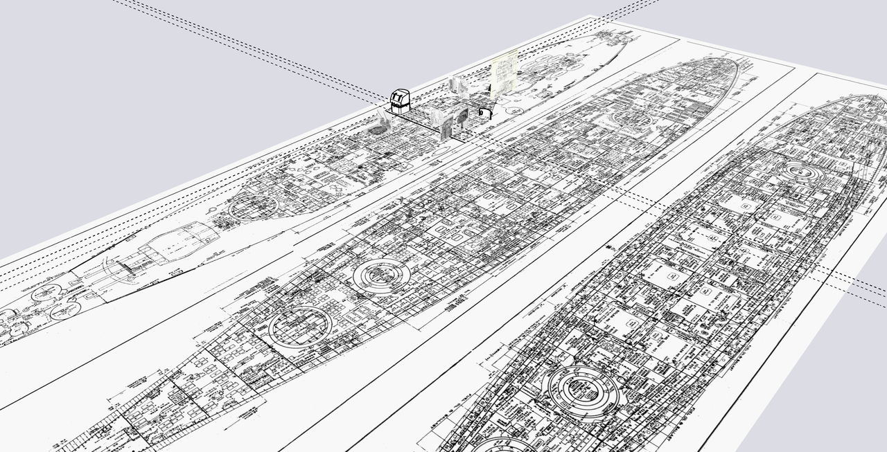
When overlaid in correct resgistry I am able to model in full size the paths of the curved powder and projectile hoist trunks. These trunks are designed like this deliberately to mitigate fire from spreading from the upper decks to the magazines.
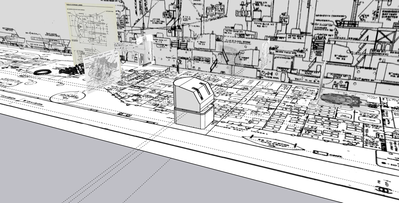
And I was able to accurately scale the Ready Ammo Room both in area and height by matching to the full size floor plan.

I erred in my design by including a lip around the rooms roof. It is flat.
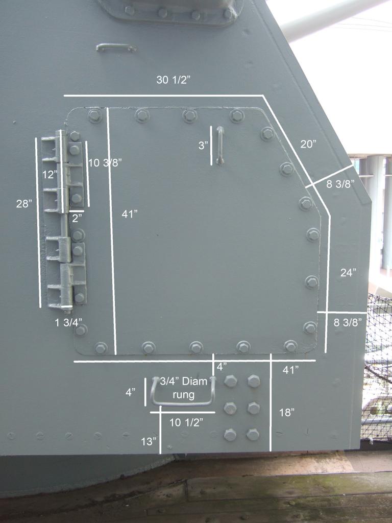
I also found very good data on the design of the Quick Acting Watertight Door (QWT). It took a while to search through hundreds of images until I hit on a sight that manufactured the style used by our Navy with great head on images on which I could draw the door. I also took screen shots from Ryan’s USS New Jersey video “Doors”. With these sources I was able to create a very respectable prototype.
Here are the three drawings I used:
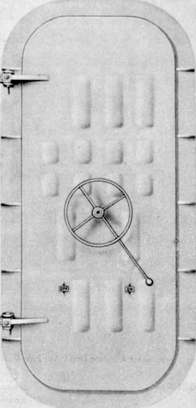
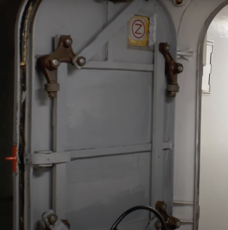
Outside:
Inside:
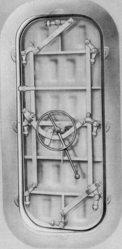
And then the best… the door without the hardware where I could get good fixes on the positioning of the dog pivots.
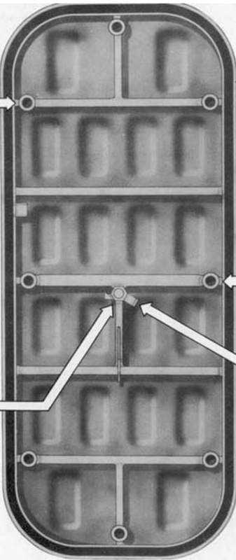
This was a closeup from Ryan’s vid. It shows nicely the roller dogs.
I drew the door in layers and 10X scaling. Sketchup has a trouble with working with curves especially when doing contours in FOLLOW ME. If the segments are too small, it leaves them out and makes holes, whereas when enlarged it fills them complelety. When you shrink the drawing back to original size, the filled areas stay put. I don’t know why this is, but it is. To make those bulges, I produced external rounded rectagular shapes and internal ones and bonded them to the drawing on both sides ensuring that there was some material thickness between them. They’re printing now, so I know if there was enough material to produce a viable part.
I then produced the frame as a component and finally overlayed the dogs and all their operating links. Some of the links were challenging since they have curves that enable them to clear the other parts.

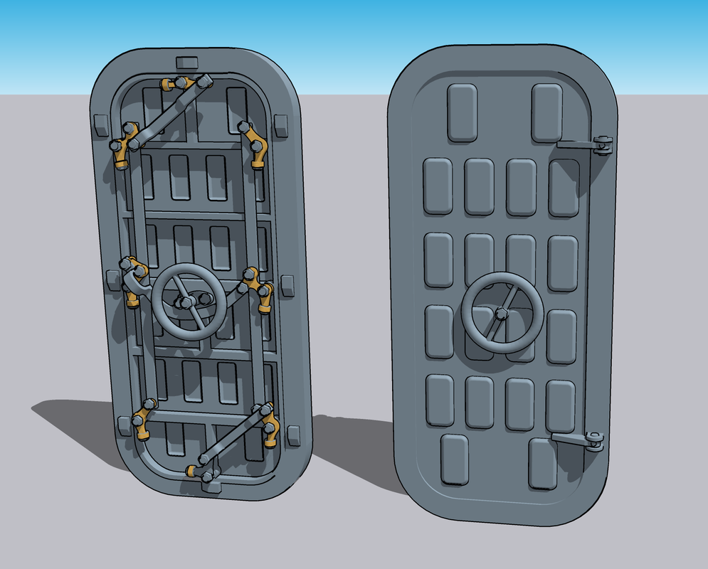
And here’s the finished product showing both sides. The real door has an extension lever on the wheels to give more torque. These would be too frail for printing and I’ll attempt to add them with wire. I am attempting to print the doors as a single part. I will see how that works out. I also had to thicken everything. At scale thickness many of these peices would not be viable. The beauty of 1:48 is you can really lay on the detail and have a reasonable chance that it will show up.
As usual, I print multiples. I will probably need at least this many. I’m also contemplating printing the entire rear curved wall of the gun house including the hatchs and details. It might be the easiet way to go if it all fits. Otherwise, I’ll print the curved corners with rabbets to seat the styrene walls. That will work to, but won’t be as elegant.
Whew! That was a load of stuff. Now I’m goint to check on the print which just finished. Let y’all know how that worked out.
Print was marginally successful. The handwheels failed as I expected, and rollers failed to form on the bellcrank extensions. They were highlighted in pink in the slicer, but I thought they’d make it. I’ll print the handwheels separately and add them post clean up. And I’ll get some supports to those rollers and print again. Otherwise, they look pretty good. All the arms and bars printed.

3 Likes
Your drawings and QWTs are superb! It’s exciting to see the detail on your QWT’s.
Yes, all rear wall doors, spent shell ejector scuttles, access plates, etc. are curved and follow the curvature of the mount’s wall. When closed, they do stand out from the wall, varying from about 1/8" to 1/4" (3-5 mm), enough to be noticeable even in small scales. The variation is clearly what one would expect as a normal part of WWII-era steel mass construction.
If you need more ship plans for this and other projects, we offer more than 200 for free download. Most are US Navy general arrangement drawings but there are some construction drawings, too. Link:
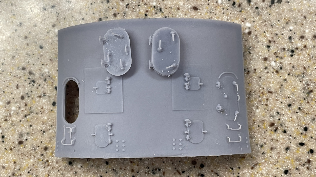
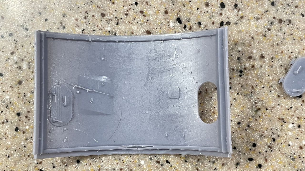
Below are a few photos of how the doors, hatches, access plates, etc., print in 1/200 and 1/128 scales integrated with the gunhouse so in 1/48 they should look really good.
Interestingly, when Trumpeter released their 1/200 scale USS Missouri BB-63 and USS Iowa BB-61 kits, they included the wrong 5" mounts. The Trumpeter kits have cruiser 5" mounts, Mk.32s which have a different shape. Once you see them on those kits, you can’t unsee them.
Very Fire made a similar mistake with their new 1/350 scale USS Atlanta CL-51 kit. Instead of the heavy Mk.28 mounts they should have included, Very Fire included lighter Mk.32s, duplicating the same sprue from their Cleveland class cruiser kit. Again, once you see it, you can’t unsee it. Later Atlanta cruisers of the Oakland subclass did have lighter Mk.32s, installed to help reduce stability problems of the class (the ships were top-heavy). But the early ships of the class did not. The early ships had Mk.28 mounts or a mark that had the shape of the Mk.28.
Cheers!
3 Likes
They really look great. I’m hoping the 1:48 comes out as well. I’m going to print the back bulkhead as a single piece with the door detail. I may have one door openable.
Regarding the QAWT… The reprint looks good, but useless! The door I drew is not used in the magazines. Jim Slade and Ryan sent me photos and information about the magazine doors. They’re not quick acting, but have individual dogs and they’re much smaller. I will share and keep the full-size QAWT door since it’s used a lot of places onboard ship.
I will take a look at the plans available on Model Monkey. Ryan said that much of the structural work in the magazines is hidden by insulation and cooling coils. They were basically large refrigerated spaces. His pictures were all closeups of door details (which I asked for), but I have no idea about the overall arrangement of the rooms. I will eventually get it right.
2 Likes
The Model Monkey did not have the plans that I would need, but I did correspond with the owner. He follows both of my turret builds and was very complientary. I asked if they would market STLs that I produce and he said they don’t do that, but Shapeways does.
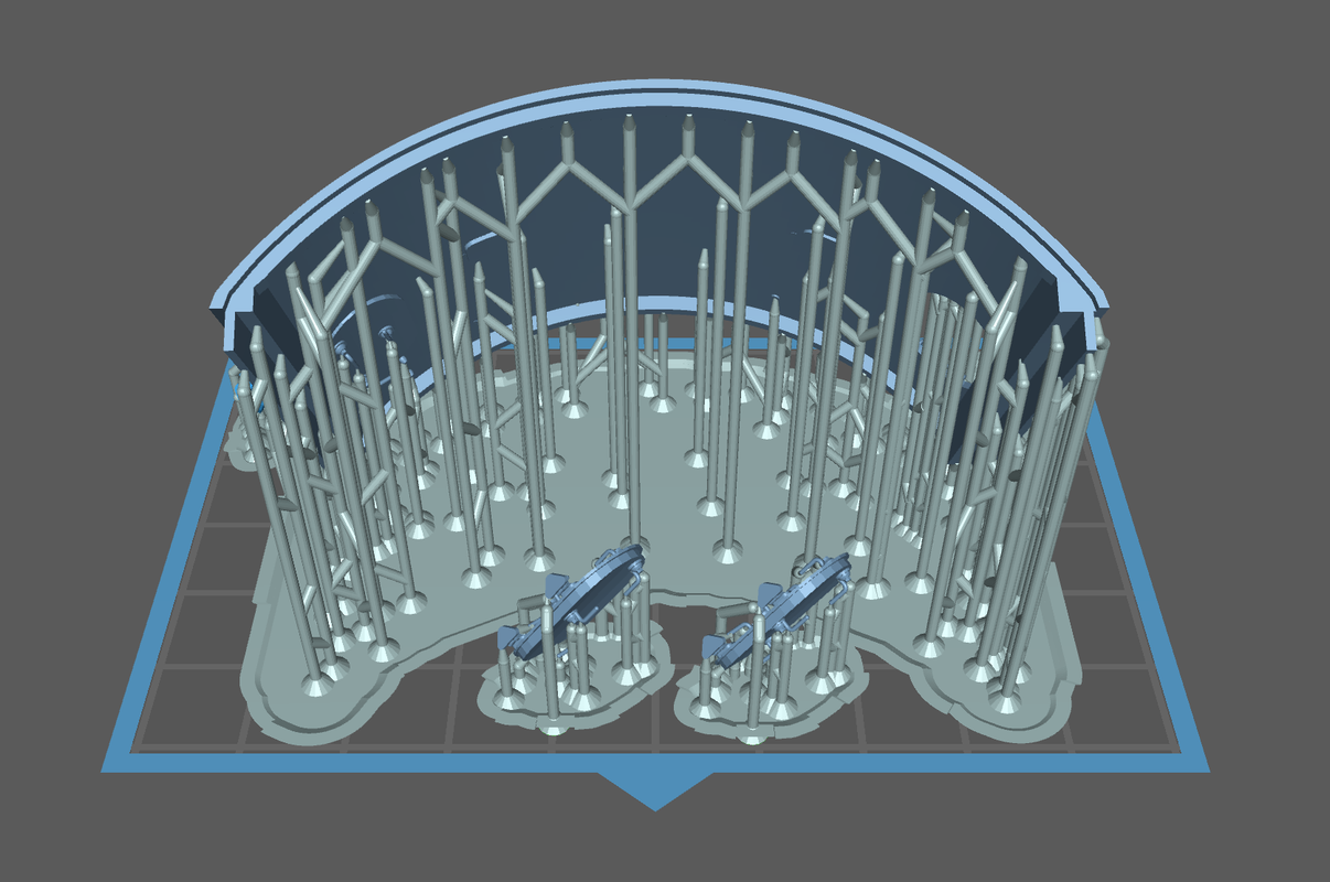
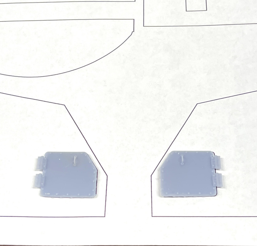
Based on information from Ryan and Jim Slade I completely redrew the magazine doors. There appears to be two types, both smaller than the standard QAWT that I drew eariler. They’re the same width (26"), but significantly shorter at 45". They are also locked by individual dogs (8) and have the pass-through scuttles where the powder canisters are passed from the powder magazine into the projectile magazine where the dredger hoists are that take both (separately) up to the ready ammo handling room.
I’m going to print the door complete with all the levers attached. I believe it will work as long as I don’t break them all in handling. I can always subsitute wire (I did this in the big turret).

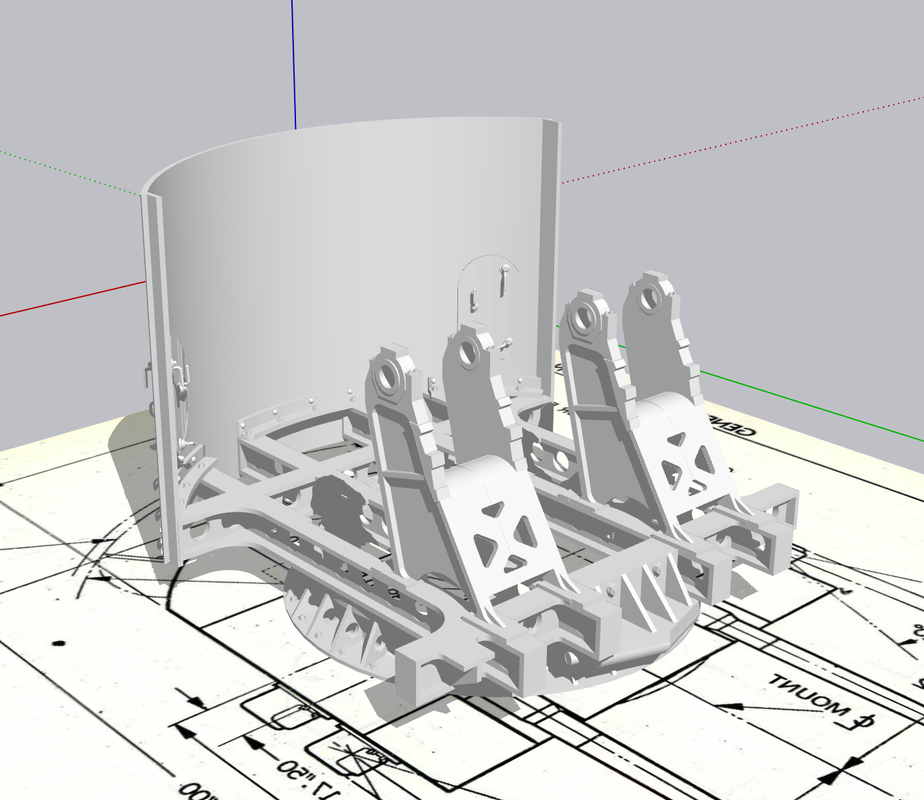
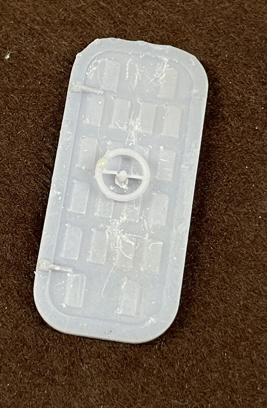
Here they are installed in the partitiion that separates these two spaces. There’s still a ton of work and research I need to do on them to make this a viable model.
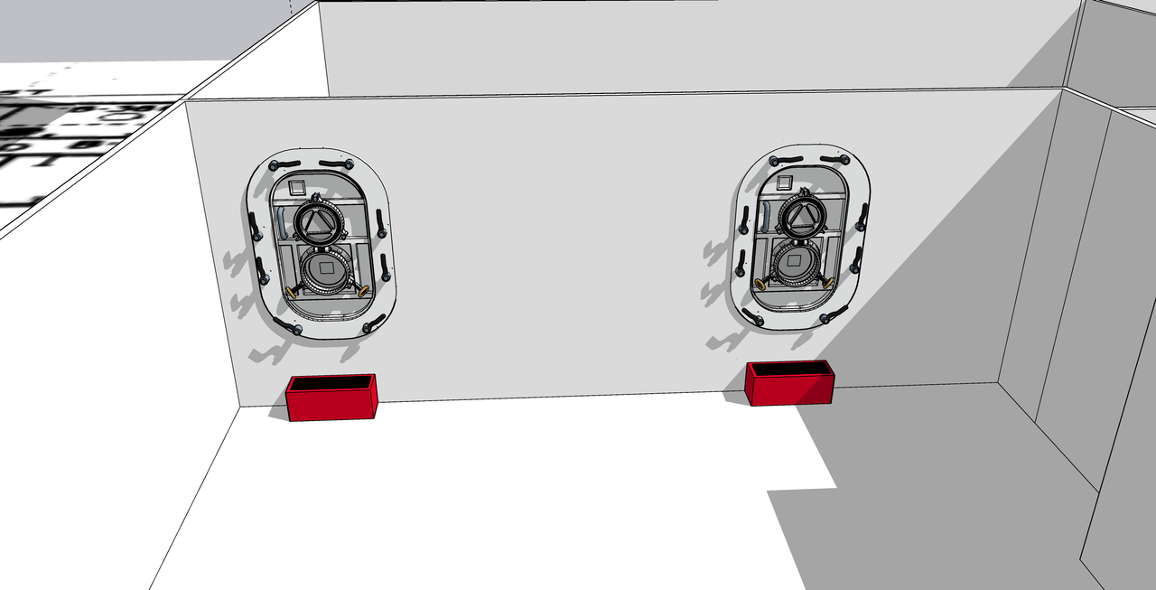
The larger doors have a 7" sill, whereas these have a 24" sill requiring the step to make them easier to negotiate.
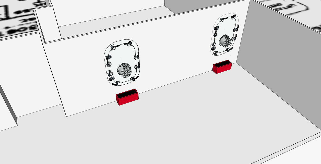
Here’s the opening side. The floor plan shows which direction the door swings. I now know that the black bump on the door’s symbol is the scuttle in the middle of the door. There is also a line on some of the door symbols that shows the handwheel of the QWAT door. Then there are the rest without specific symbology which I have to figure out.
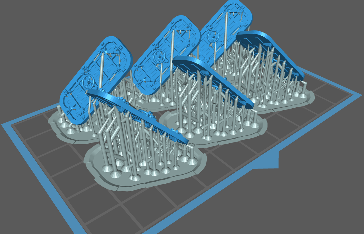
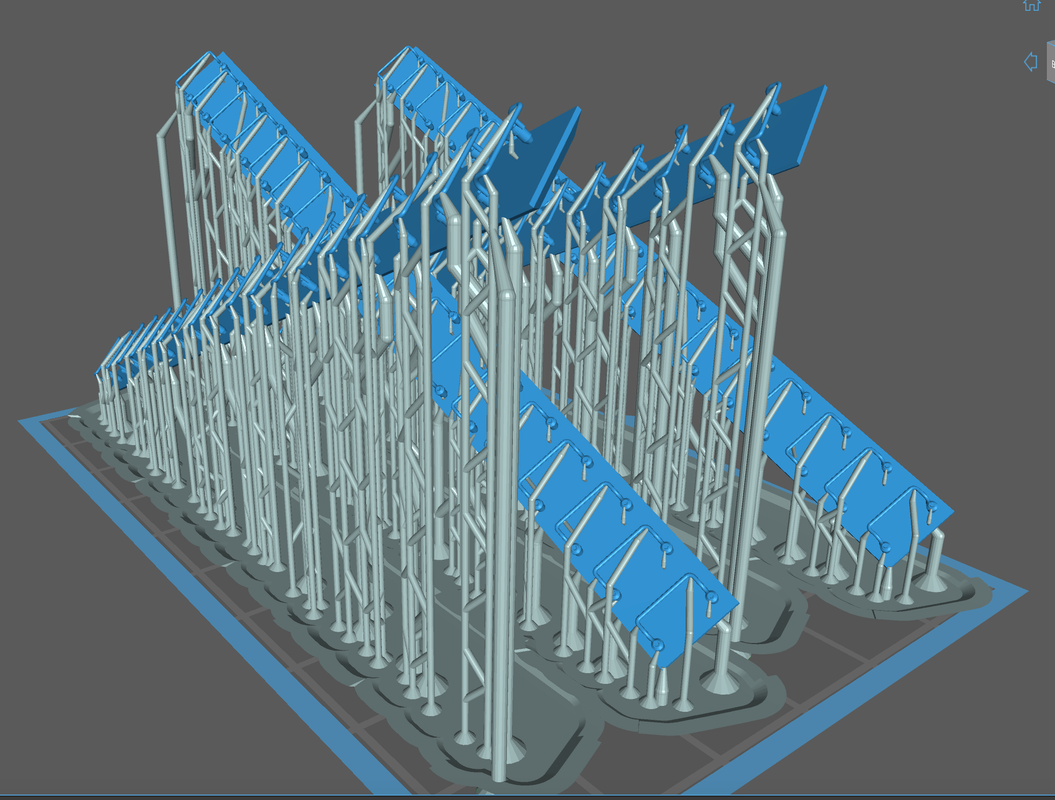
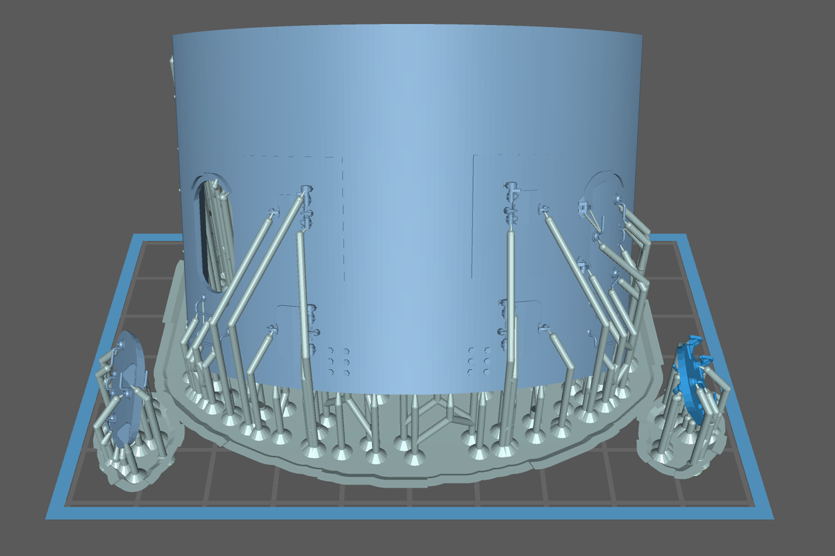
Here’s how they’re going to be mounted on the printer. I’ll put them on tomorrow. Print time is less than two hours.

7 Likes
Haven’t printed the new doors yet. But I have been busy. I nailed down the turret curved back with all the doors, hinges, latches, foot rungs and bolt heads. I did it at least five times until I got it right. Each time I thought I had it all tied down, I’d put the STL version into the slicer and then would see something was wrong. Either some details were imbedded too deep or not deep enough, or they tilted in some way. The I saw that I didn’t use enough segments on the curved surface and it looked terrible. Then when all that was done, I found that somehow the pieces was about 3 scale inches too narrow. So I to fix too. All told it took much of yesterday and today to get it right.
SketchUp does not actually draw curves. It draws a series of straight lines that approximate curves. For circles the default is 24 segments. That’s quite clunky and in 1:48 would be very noticeable. To fix it you’d have to sand all the peaks down to curves, but all the details are part of the print and they would get in the way. For the tools that make curve parts, the default is 12 segments. When I’m doing a surface that I want to print almost a true curve I go minimum 48 and even better 96 segments. SU’s computational engine works harder the more segments that curves have. For graphic display purposes, SU smoothes the curves, but the segments are actually there and when you export as an STL, there they are.
Here’s an example:
The drums are R-L 24, 48 and 96 segments. With the curve smoothing they look like perfeect cylinders and if I were to print or render this, it would look great.
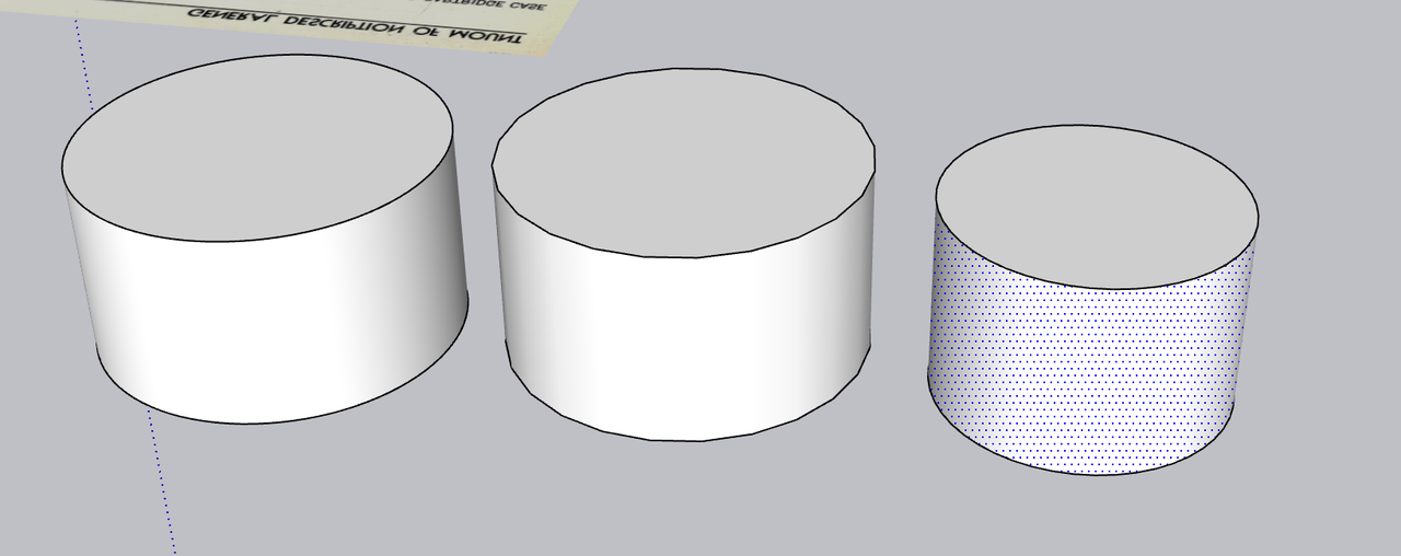
When I turn on “Show hidden surfaces” you see the segments, although the surface is still smooth.

But after STL conversion and loading into the 3D slicer, this is what the cylinders actually look like. In 1:48 that flats will be very noticeable.

One of the most difficult aspects of drawing the back wall was putting the details onto a curved surface. SketchUp works on an X-Y-Z coordinate system with X being the red axis, green the Y axis and blue the vertical Z axis. It is always best for many reasons to orient your drawing with the these axes which facilitates moving things around. That works great on a rectangular object with 90 degree corners. With a curved surface like this wall, only one spot in each quarter turn aligns with the axes. I drew all the details off the model, ensured they were each printable solids and then embed them in the curved wall’s surface. I actually push them into surface just a bit to ensure that the details don’t form detached in space. I they have separate supports, which many will, they could completely form, but not part of the print. When the wall surface is not on axis, when you move the object in the x or y direction it moves in an angle. So if I wanted to put the part in a specific location, I had to zig-zag and creep up on it. It took a long time.
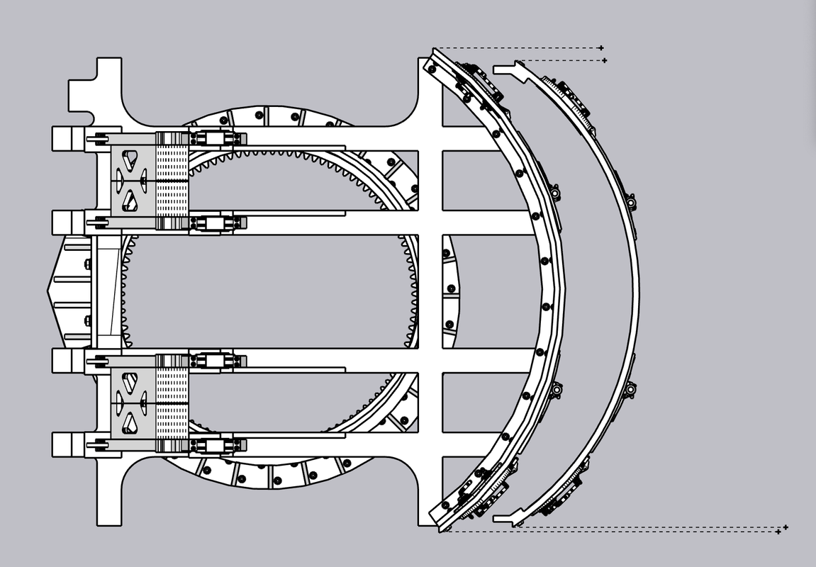
Then about 3/4 the way through the exercise, I decided to copy and paste the completed wall to the master drawing. When I placed the wall against the rest of the gun house I drew previously. It didn’t fit! Frankly I don’t know when the size change. I say “changed” because the original curved wall was that gun house’s back wall which I copied and then added the two scale inch depth. This image shows the first wall I drew superimposed over the corrected wall. This difference was unacceptable. The side walls have to intersect with the 0.040" thick side walls with no gaps.
Here’s a vertical look at the wall over the main frame. Again, the wall has to key into the frame correctly. The new wall is on the frame and the incorrect one behind it.
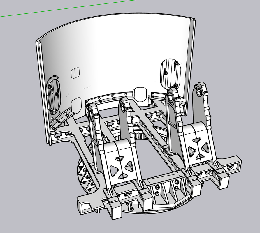
I couldn’t just stretch the wall to fit. I had to start over. However, I was able to take all the details off as a group and preserve them. That sounds easier than it was since they were on slightly different distances from the center and lying on slightly different radii. Lots of trial and error. Notice I’ve thought ahead for a change. I included the mating flange that will connect to the straight side walls. There is angle brackets on the real turret that do the same thing.
Here’s how the finished product will look. Notice also the curved angle bracket that secures the floor and back wall to the frame. This is not the fianl look for this part. I have to study the pictures and drawings more.
And the finished front.
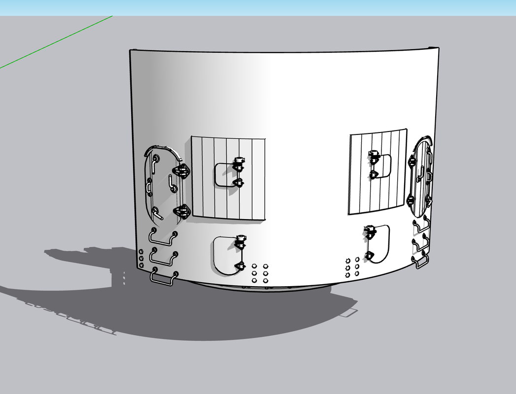
And in a more rendered way.
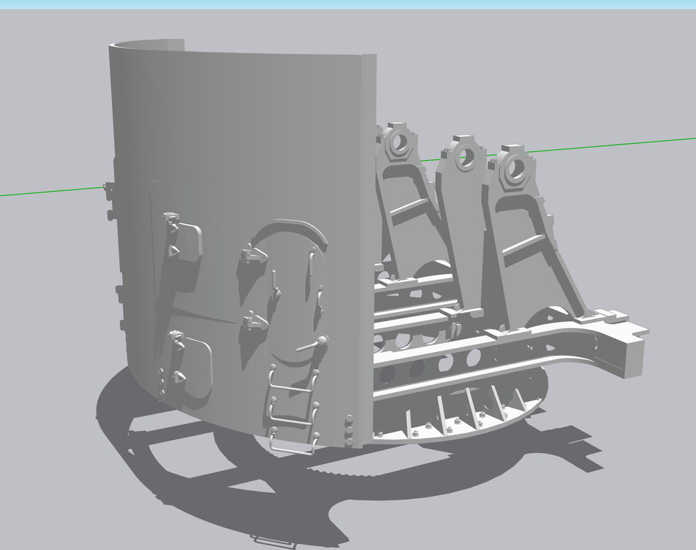
Here’s how the wall fits on the printer.
I’m using heavy supports on the wall itself and a lot of them. It’s not that there’s that much surface area, but it’s a bit heavy and that weight starts to play a part in the support scheme. All the details are supported by fine supports. Notice how fine the facets are on the surface using 96 segments. Very light sanding will remove them entirely. In 1:48 you can include ALL the detail.
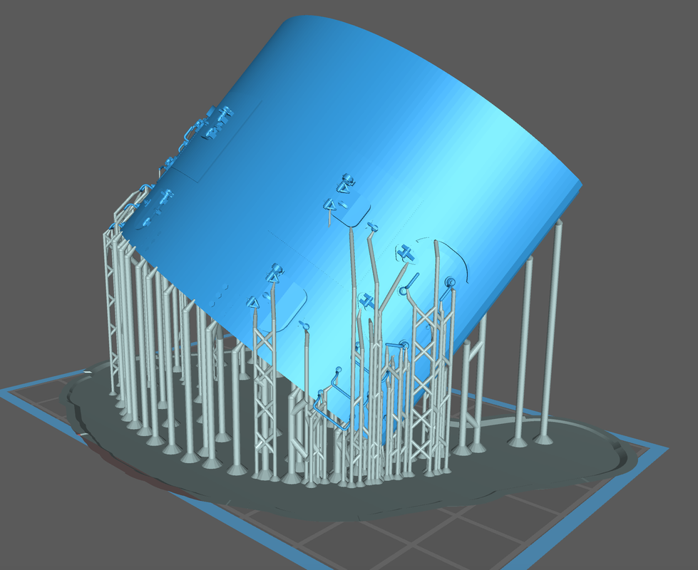
While the attached foot rung will print, I’m worried about thier longevity, especially the ones hanging down below the lower edge. I will surely break them off. I am printing them in bulk so I can replace them if necessary. I’ve included a 0.020" stub on them that will fit into a drilled hole. Each rung has to be supported separately. I can make many of these fairly fast.
We’re heading back East on Tuesday. I may do some work tomorrow, but after that we’ll be gone a week.
5 Likes
This is going to be insane when completed. The work you are putting in just amazes me…Cheers Mark
1 Like
Thanks Mark! I need all the encouragement I can get.
I finally unloaded that batch of QAWT doors and they did come out pretty well. The handwheel cross bars are almost too fine to hang together, but even there I did get some successful ones. The operating bars are so thin they’re kind of floppy and if I were to do them again would make them about 2X thicker. As I’ve said before, real world material sizes sometimes don’t translate successully to the model especially at 1:48 or smaller. Regardless, I’m happy with them. They will work and I don’t know where to put them in the model. It gives me confidence that any other doors I produce will work.
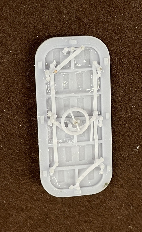
And the flip side. All the major supports were on the front side and the only supports on the mechanism side were supporting the dog rollers and removal didn’t damage anything to badly. I hadn’t don final sanding on the edges.
And here’s the second one I cleaned up. I still have four more that I haven’t trimmed that are in the spares box. This one did have the edges sanded. When primed and painted they should look pretty spiffy.
When I woke up this morning and did my usual model ideating, I realized that I could use the backing plank that I use for the ladder rungs as a drill jig to add them manually. The correct spacing is 11.5" and I had arbitrarilly a little over 13". I redrew the layout to have that spacing and set it up for printing.
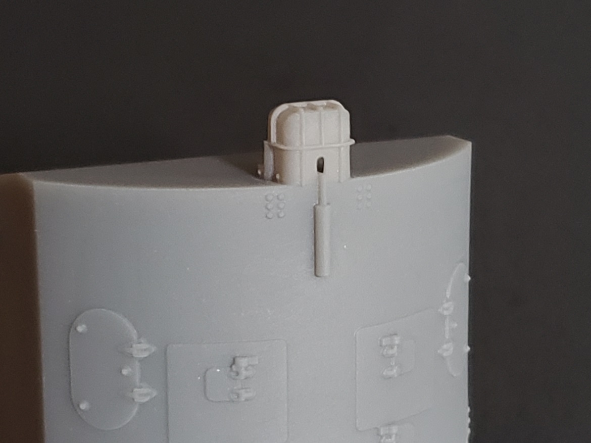
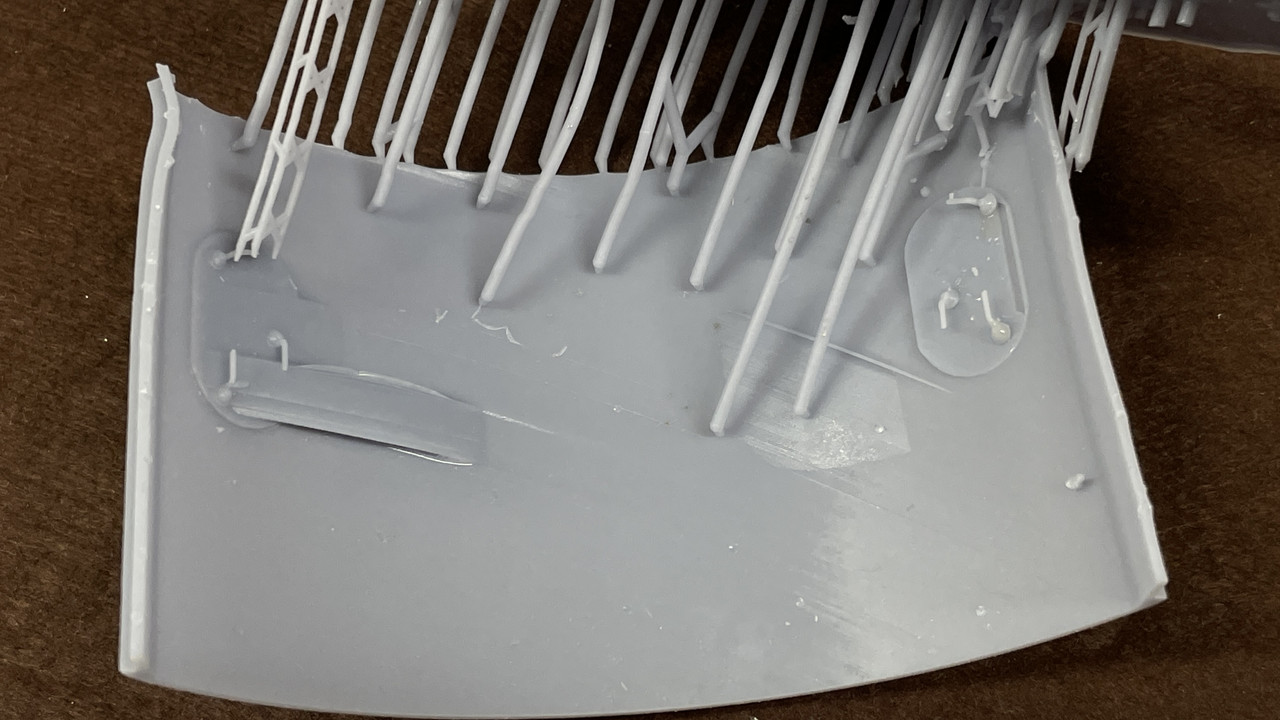
Then, this afternoon, I put the back wall in the printer. 6 hours later here’s what I got. It wasn’t totally bad, and, in fact, since it’s quite an unusual piece to print, I’m not too upset, but there were some weak points.
Here’s as it came off the machine looking at three views. I had removed some of the supports around the delicate details, but did not post-cure.
On the left corner there was some distortion. I don’t know what cause it, but it’s usually a support failure. I will have to evaluate whats going on in the slicer. The handles and steps all formed nicely.
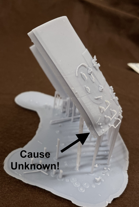
Note the delamination of the base raft! That’s also strange showing there was good adhesion to the build plate. Could be too much attraction to the FEP.
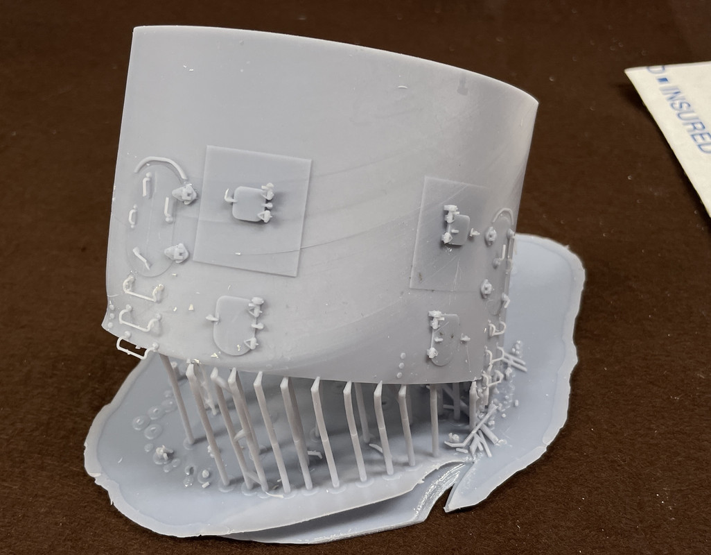
No distortion on the right side!
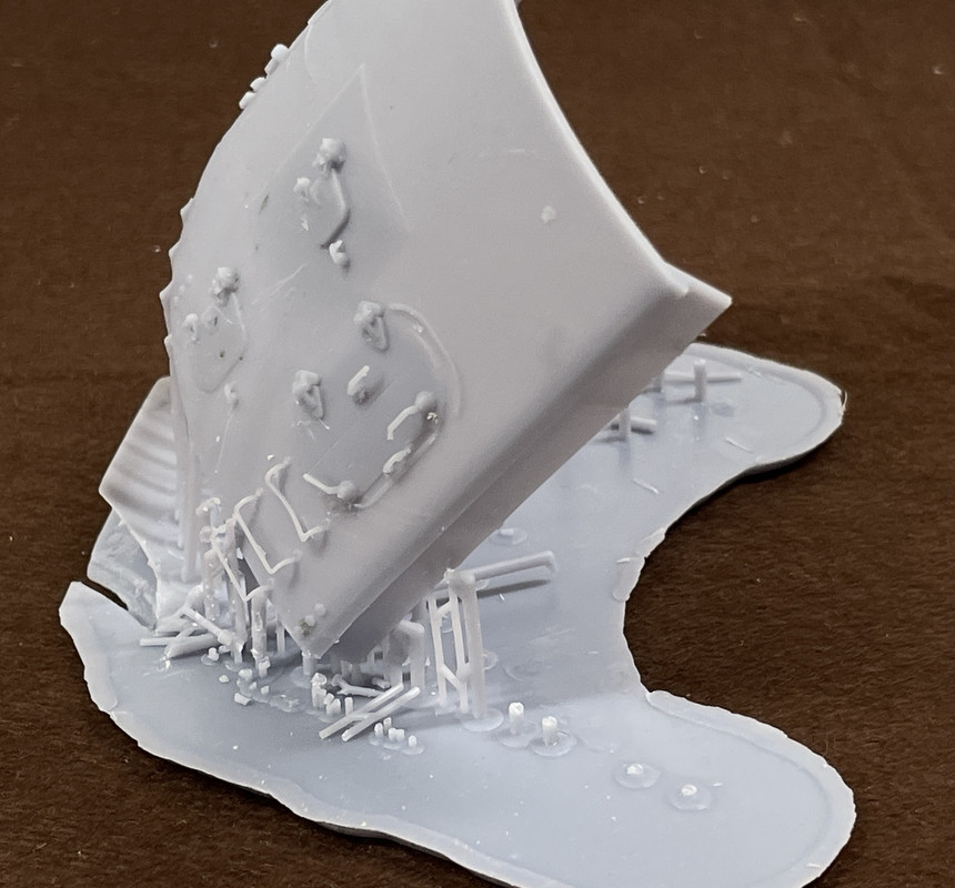
And the back. Strange things were going on in the back.
Some remarks about this…
I thought the drawing was finalized, but the latches on the right side cartridge chutes moved out of position. The center section bolt heads are not there. That too is a drawing error.
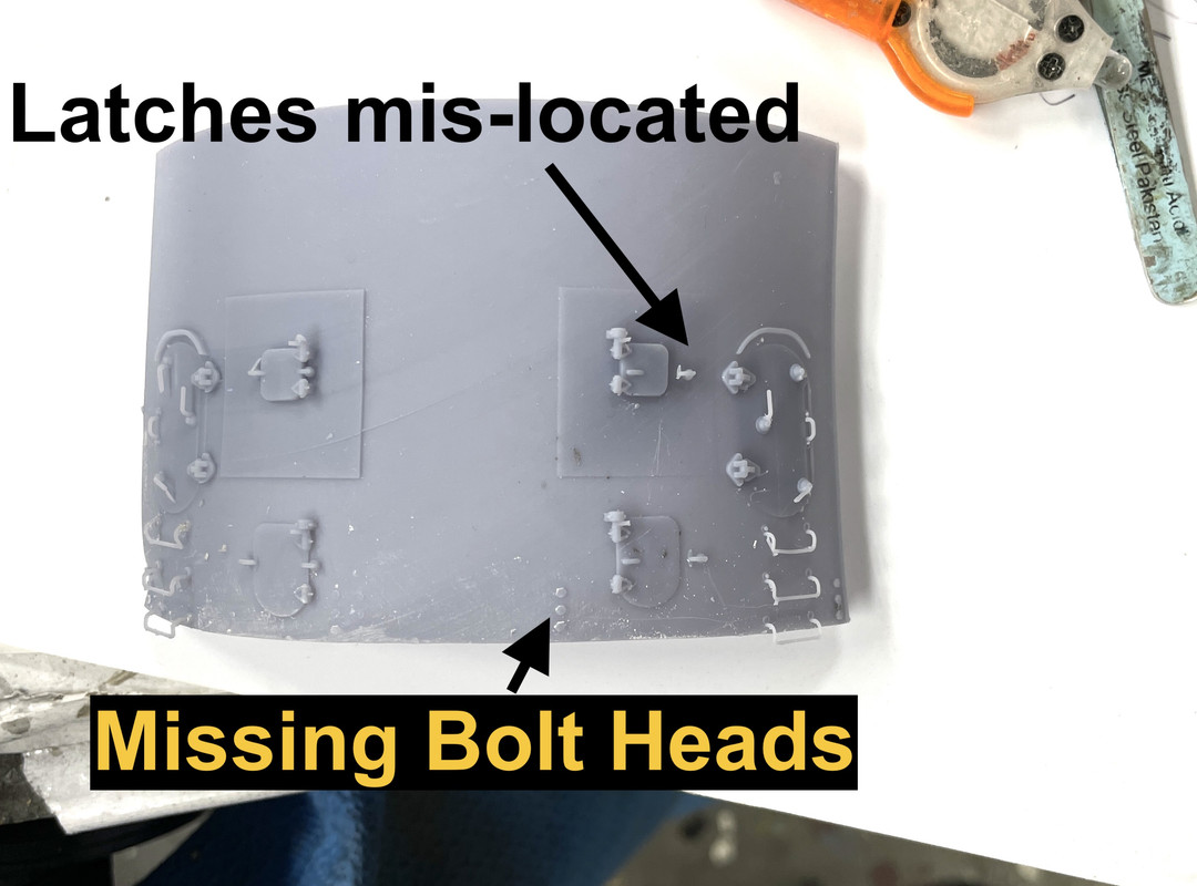
BTW: As predicted, I already broke those bottom two foot rungs. I will have to add them late in the build and maybe make them out of metal.
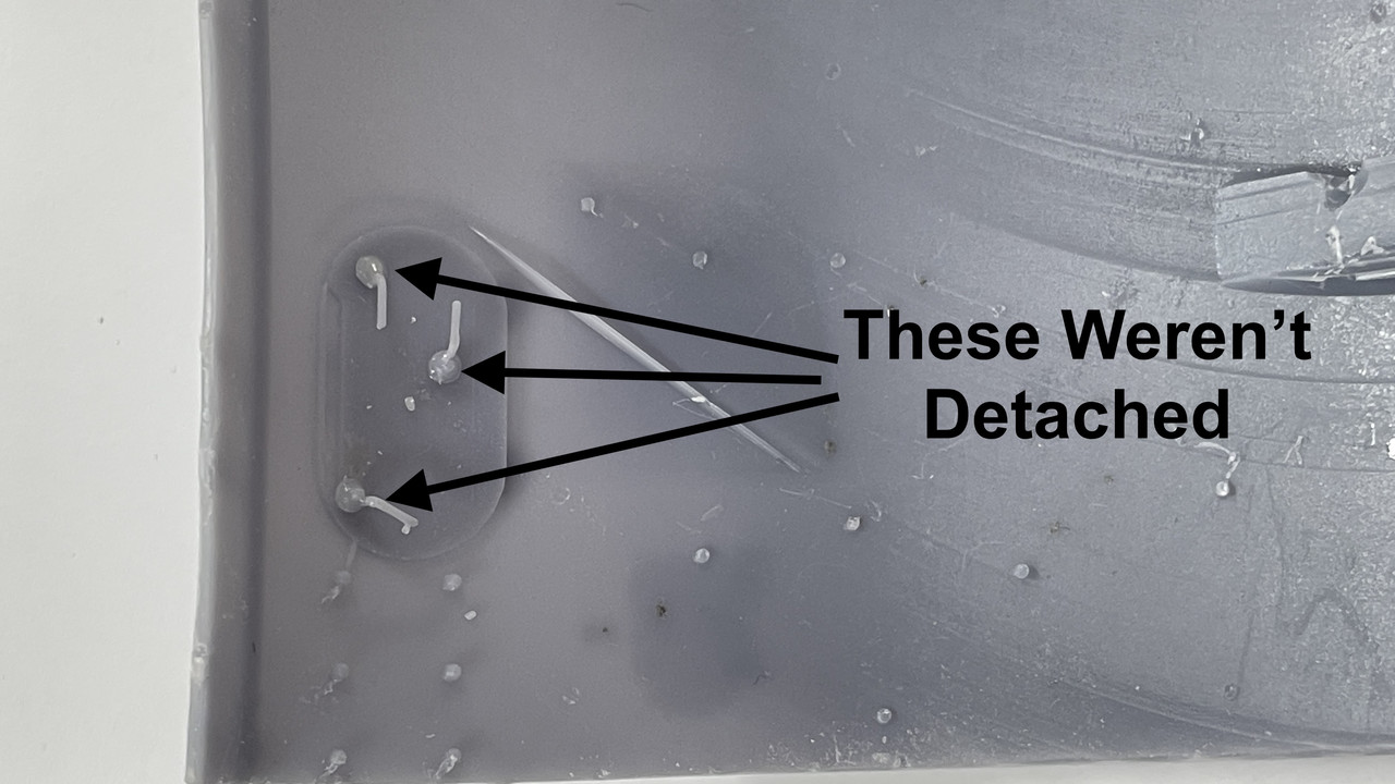
In the back, the right side latch dogs were not attached to the surface. Remember was I was saying about have to be sure their embedded in the drawing. Well… I guess these weren’t. I was able to put them back using Bondic, but I’m not keeping this part for the model. It’s going in the scrap box and will be used for parts if necessary.
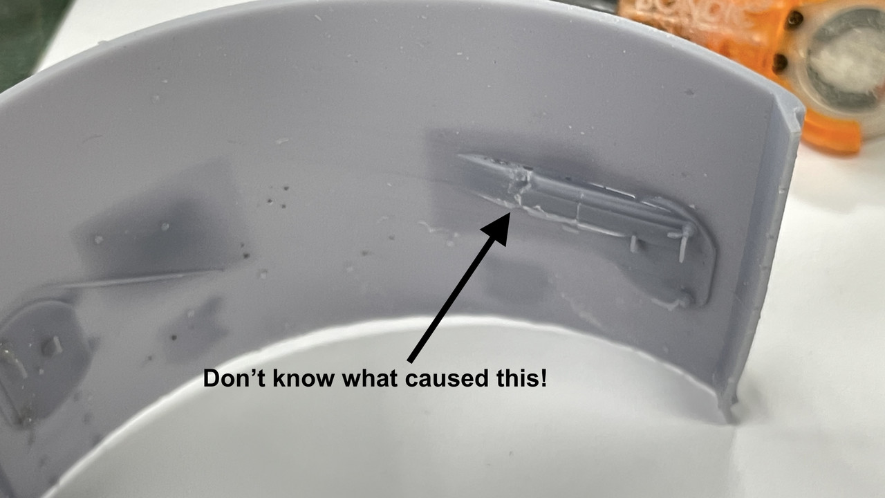
And then there’s these malformations. I’ll have to explore this defect. Because it’s actually more material, I can grind it off if I need this part.
I now have the powder handling doors in the printer. They’ll be done about 11 p.m., but I’ll get them tomorrow. If they come out as nicely as the QAWTs did, I’ll be happy. If I can’t get the curved wall to print effective, I can print the add-ons and build it out of styrene. There’s always a way!
5 Likes
I would very tempted to design the doors as two parts, inner and outer. This will hide the attachments points and any clean up work.
I would also make a jig for bending wire later for the rungs so they are all the same.
I would also be tempted to print the hatches separately with openings in the rear wall.
Great work as always. ![]()
1 Like
Again masterly work… I will keep track of this thread. Maybe change the title, as Takom is fully out of the equation on this one?
Thanks. How do I change the title? Doesn’t seem to want to be edited. Also, I did as Tank suggested and opened one of the doors. I report more about it later when we return from the trip. I’ve also added some stiffening ribs to the wall itself to help stave off the warping.
1 Like
I fixed it for you. There should be a pencil to the right of the title, click it and it will allow you to edit it. You can also go to your first post and click the pencil at the bottom right and it will allow you to edit the post and the title.
That works! Thanks!
Hey Myles, quick question if you don’t mind: what sort of wall thickness are you making the parts to?
Looking at printing off my own project, but not sure how thick to make the walls? ![]()
The curved wall scale thickness is 2.5 armor. To simplify construction, I’m using 2” which is about 0.040 in 1:48. That’s a convenient plastic sheet size for the rest of the flat sheets in the gun house. That’s about the thinnest I would print at for structural integrity. The wall of the 3D print scales out at 2.5".
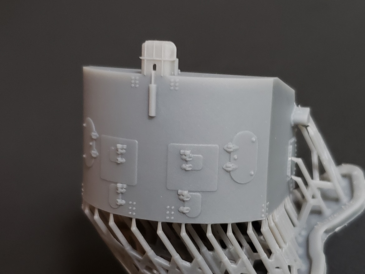
After studying the part set up AND the part’s design itself, I modified the rear panel and then changed the setup on the printer. For the part redesign, I added ribbing and buttressed the corners to stiffen the structure and add more beef so the styrene flat walls have more contact surface. For the support setup, I placed the part on the plate simply tilted back and not slanted. I removed the bottom ladder rung since these broke off almost immediately before, and even then, am printing dozens more that I can apply much later in the build.
This in looking at the inside. You can easily see the added material to stiffen the structure. Top now forms a lip so the roof can set down inside the back wall.
And here’s the front view showing the individual light supports picking up the exposed details that showed up as trouble spots in the slicer. I’m making the piece with and open hatch for more interest.
I printed them today and here’s the output. I will use this. As I expected, the foot rungs didn’t do so well and I lost one door dog which can be substituted with 0.010" wire.
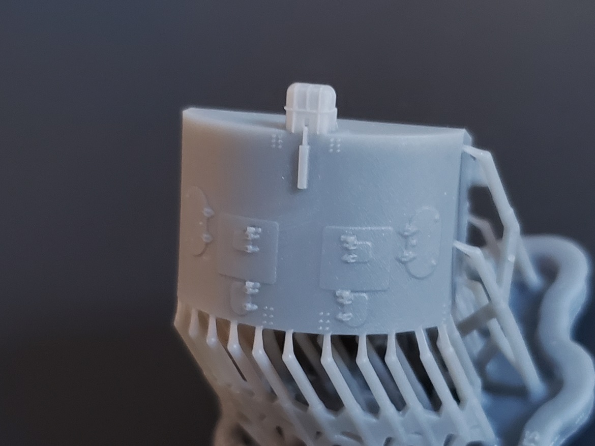
The rear still shows one of those odd bulges as happened in the first attempt, but this one seems easier to remove. It does not show up on the front side. And there are not print lines in the front surface. It’s a pretty good print all in all. The inside door dogs printed nicely… amazingly. That delamination on the bottom rib is not a worry either and easily fixed with Bondic. Not worn wasting the resin on another print. This was post cured, but not final sanded.
I have the ladder rungs printing now and have another crack at those powder magazine doors. With these printed I have to get back to the drawing board and produce more parts.
I’m going to be making a clinic presentation on the Construction of the 16" Gun Turret at our Military Modelers Club of Louisville Regional Modeler’s competition being held on Friday thru Sunday, September 21–23 at the Triple Crown Plaza in Louisville. I’m titling the presentation 21st Century Modeling: Model Building+CAD+3D Printing. There are going to many vendors and exhibitors. It will be a wonderful show.
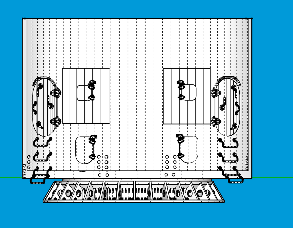
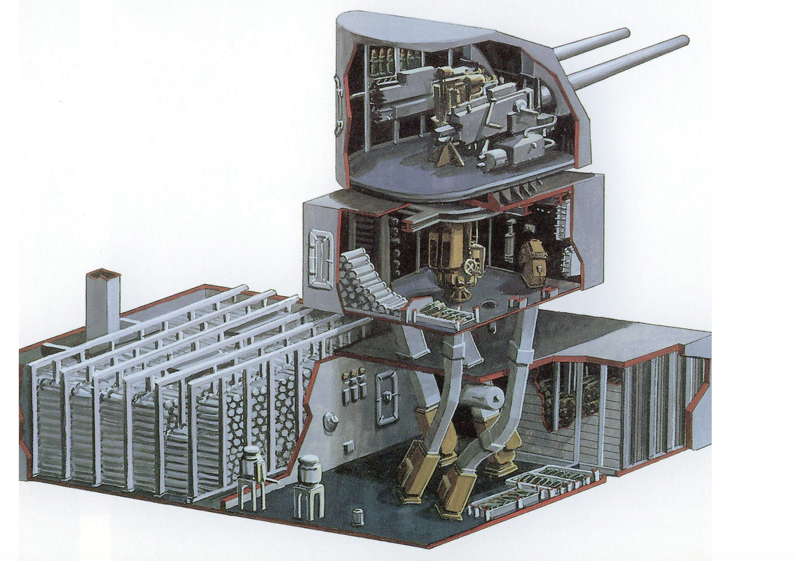
In a messaging session with Ryan Syzmanski, we’ve decided to model the magazines in an “artistic” rather than prototypical way. Due to the intermediate non-functional deck spaces (non-functional regarding ammunition movement), I’m going to model it based on this iconic drawing.
My model will be more detailed and accurate than this image. I also suggested to Ryan that we display a graphic to show the actual relationship between the turret and the magazines which do not lie directly below any turret. There are two decks between the main deck and the magazines that would not add value to the model.
I tried out my new V-Ray rendering software which came with the SketchUp Studio version that I’m now using. It’s significantly better than Podium which I’ve been using before.
Here are two examples:
First Podium: Podium handles the details okay, but really shifts the color.

Now V-Ray. V-Ray drops out the background based on selections you make. This is actually quite useful for embedding images into documents. Sharpness is the result of the image size you’re outputting. In this case I chose a small file size. It also renders much faster than Podium.

And now a screen print directly out of SketchUp: In some respects, the SU direct shot is more descriptive showing all the line work. I can display it without the lines and it looks more like the renderings.
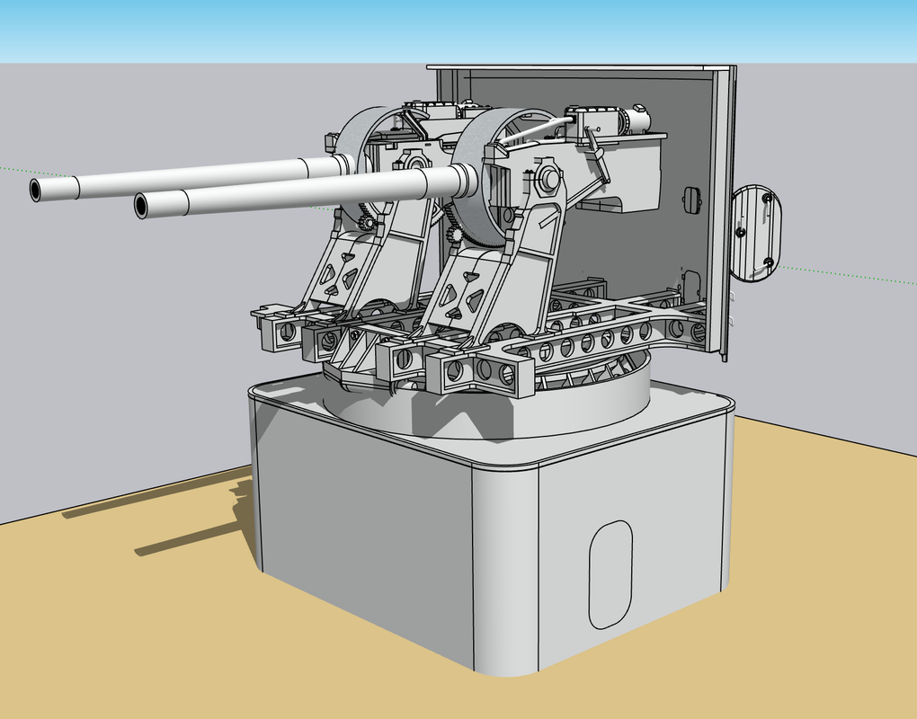
As you can see, the gun designs are almost complete. I was drawing all kinds of details based on one of my references and then realized that the reference drawing was of the gun slide, not the housing that surrounds it. The flanks of the fixed part of the gun are relatively clean. It saved me a lot of drawing time. The hydraulic piston that operates the ram, which I was trying to depict, isn’t simple. The ram is tied to a gear rack which multiplies the stroke length. The rack then operates the ram with another rod. All of that is hidden by the outer housing.
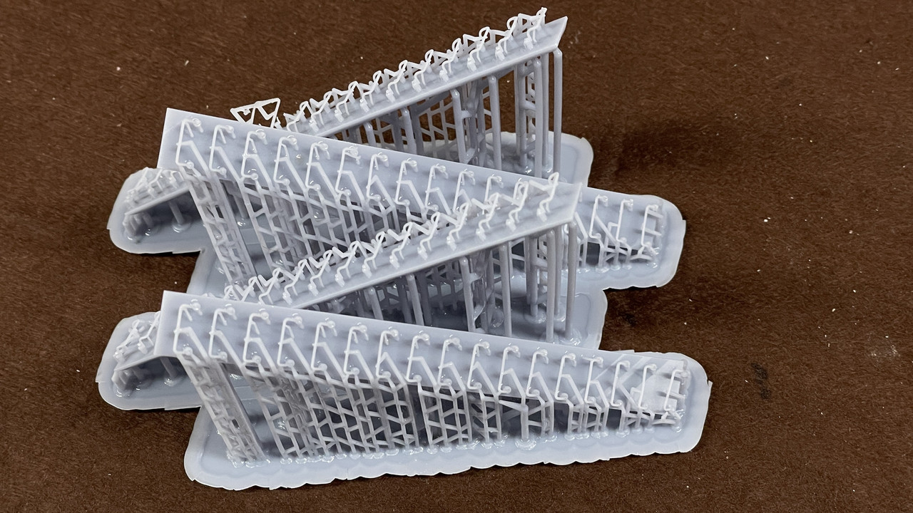
I got a nice print of a gaggle of ladder rungs. Only one did not print well due to on support letting go beneath it. I chose to post-cure BEFORE trimming the supports to strengthen the rungs to better handle the support clipping function. We’ll see…
I spaced the rungs on their support bar exactly on the 7.5 scale inch spacing as they sit on the turret. I can then drill at each point after removing the rungs and have a convenient drill jig to drill the mounting holes on the turret flanks. Now that’s thinking ahead, ain’t it? I designed the rungs with a stub end that is sized for a 1/32 drill size. It should work…
I’m finalizing the cutting patterns for the styrene turret parts. I had some clearance problems which required adjusting the gun slops on the faces. I also printed the size access hatches with their hinges, mounting bolts, and grab handle. Only one out of three printed well. Again, I used medium supports for the base and some failed causing deformation. I’ll adjust it and redo. Need to order some more resin.
5 Likes
Brilliant work, Myles and some great progress. ![]()
0.040" = about 1mm in metric. For what I’m currently working on (the hull of a ship) I’ve allowed 1.5mm = about 0.060" in Imperial. I figure this would be better from a strength point of view, but as I work my way up to the finer details in the superstructure I will use the 0.040"/ 1mm ![]()
1 Like
With the extra ribbing in the curved back, it’s quite stable. The 0.040" styrene in the roof will be reinforced by model I-beams as in the original. The joints between panels will have angle, either Evergreen styrene or Plastruct ABS. Plastruct is stronger. So the turret shell should work out okay. I also have to compensate for the weakness imposed by the cutaway areas… I’ll cross that bridge when I come to it.
1 Like
Spent a lot of time without much to show for it. Most of it was wrestling with the ladder rung prints, both in trying to separate them from the supports and backing piece, and then drilling out the jig to use when mounting them. They are too darn thin… scale, but thin. Removing them was quite painstaking and a bunch failed that had to be repaired with Bondic. There was another problem. I made some very tiny drawing errors that prevented the part from being structurally sound. One small face on the mounting lug was reversed and therefore, didn’t print. This lead to the failure of the bolt head to print that was attached to this now-missing face. Also, the rung mounting point was weak and failed many times.
I stopped messing with it and went back to the drawing board, fixed that reversed face, increased the rung diamter by 30% ]and strengthened the mounting point. It’s printing now and I’ll get them tomorrow.
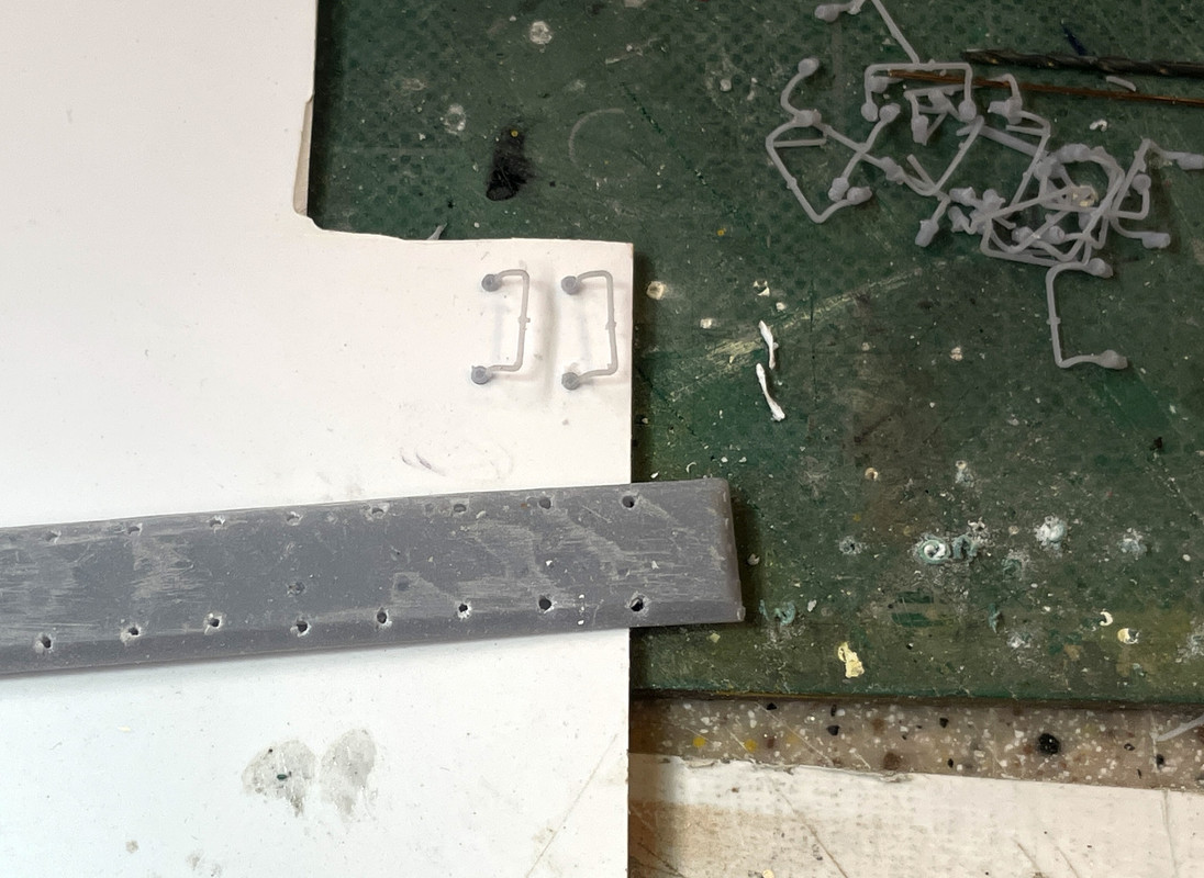
I aslo tried the drill jig idea and it worked. Only problem was some of the holes were into that chamfer area. I also changed this part too for the next print. I’m using a #57 drill, but a #56 would be better since I had to push too hard to get the lugs to seat and that leads to distortion and breakage.
I also got successful prints of the two mirror-image side access hatches. Last print failed three-out-of-four times due to insufficient support at the lowest corner. When that support failed, the part distorted in that area. I added more support and the four parts were perfect. Even the grab handle formed perfectly.
With the Fulament spring built plate I’m using, I rarely have adhesion failures, but I do get support failures. It is crucial to put a lot of heavy supports at the lowest (first) edges that form. Not only do you want to have a good, solid start to the print, but the lower supports have to support the ever-increasing weight of the part as it’s forming. It’s all proportional. A small part may look like this rule doesn’t apply. Afteral, how much can it weigh? But it’s not just gravity you’re fighting. There is also suction created due to the perfectly flat surface created betweenl the FEP when the resin layer is curing. The build plate, through the supports, has to break that seal to lift the part so fresh resin can infill beneath the part. I’ve printed hundreds of parts in the four years I’ve been at this, and still have support failures. There are guidelines, but there are no hard-fast rules.
As the part forms you can lighten the supports on the upper reaches since the amount of mass is greatly reduced. I also add light supports to all details where removing the heavier supports would destroy the detail you’re trying to print when you remove them.
3 Likes
Beautiful work. I have the Mk 38 kit from Pig Models I need to get back to.