With the 5"38 project showing signs of completion, I’m starting to think about the engine room challenge. To get 33 knots, over 250 feet of the entire center of the Iowas were dedicated to propulsion. Each of the four engine rooms generated 53,000 hp. The engines rooms were over 35’ feet long, over 60’ wide and 25’ high. In 1:48 the model’s volume would be 7.8" long, 16.5" wide and 6.5" high. It’s not vastly large. I have general understanding of the layout, but that’s insufficient. The machinery takes up two platforms vertically, with floor gratings separating the levels. I am not planning on modeling the boilers, but may change my mind.
Here’s the four engine rooms withing the envelope of the armored citadel.
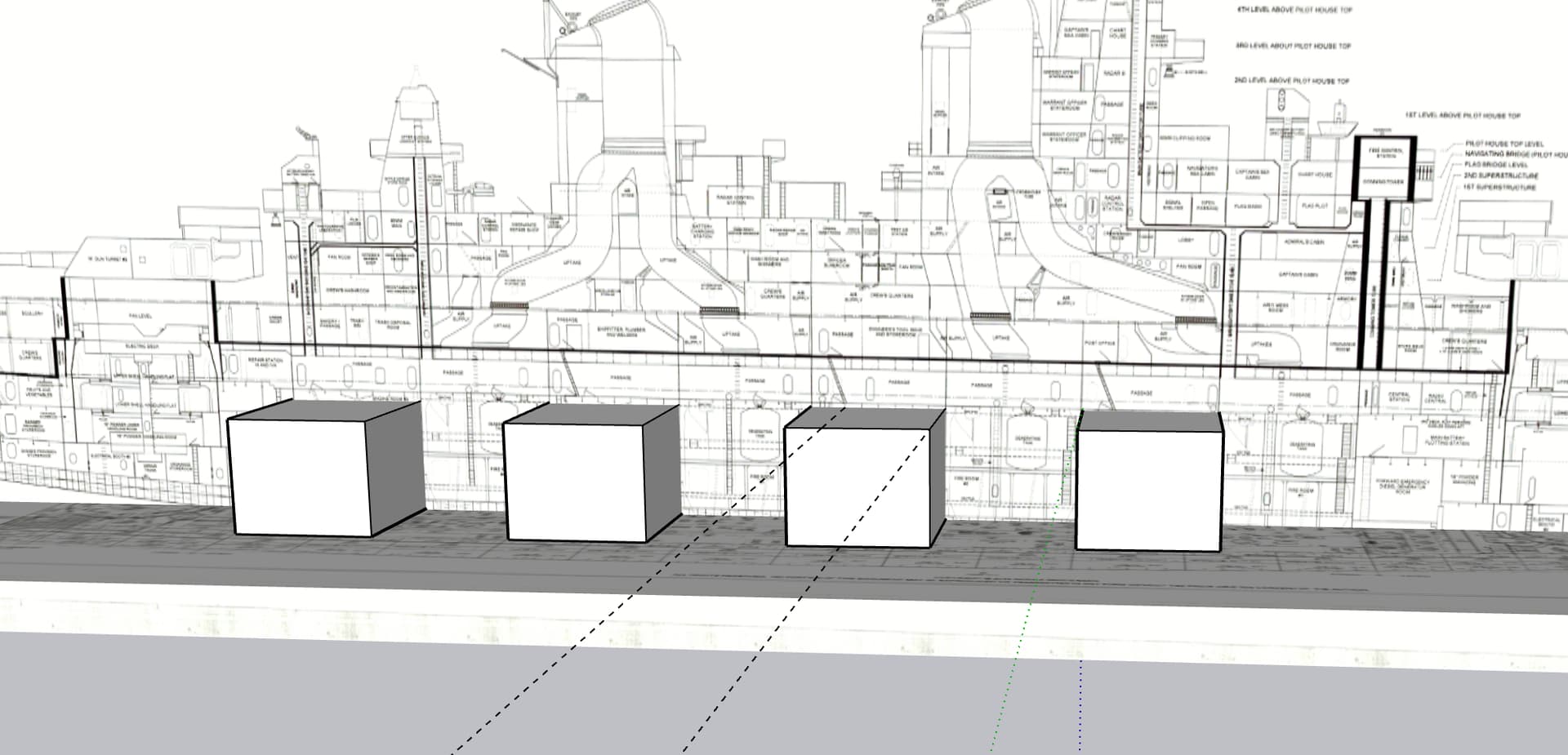
I’m aiming at engine room #3 since it was a rectangluar shape with square corners. Rooms #1 & #2 had tapered sides based on the curvature of the hull.
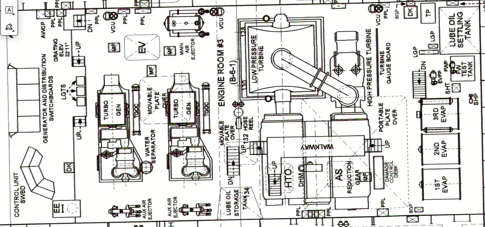
This is the floor plan of #3 from the 1st Platform level. There is the 2nd Platform level where part of this extends downward to. The low pressure turbine is very large and extends downward. The condensors are also very large and are at the lower level.
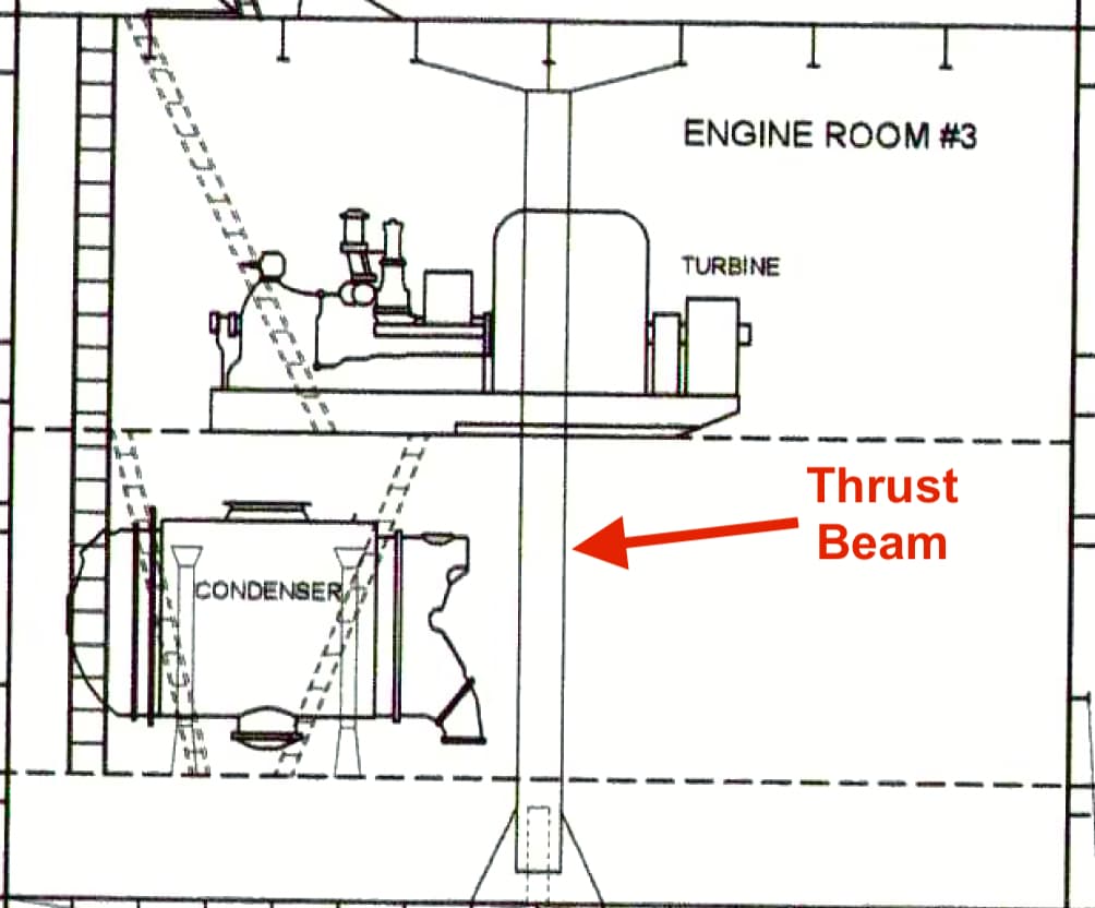
Elevation views of two rooms show equipment from different points of view. I was wondering how the 53,000 hp thrust is captured and transmitted into the ship’s structure. It’s not a simple thing. The prop thrust is captured by the all-important thrust bearing, but where does it go from there. I am assuming that the massive vertical beam that’s attached to the ship’s structure by massive gusset plates is where the thrust enters into the ship proper and propels it forward.
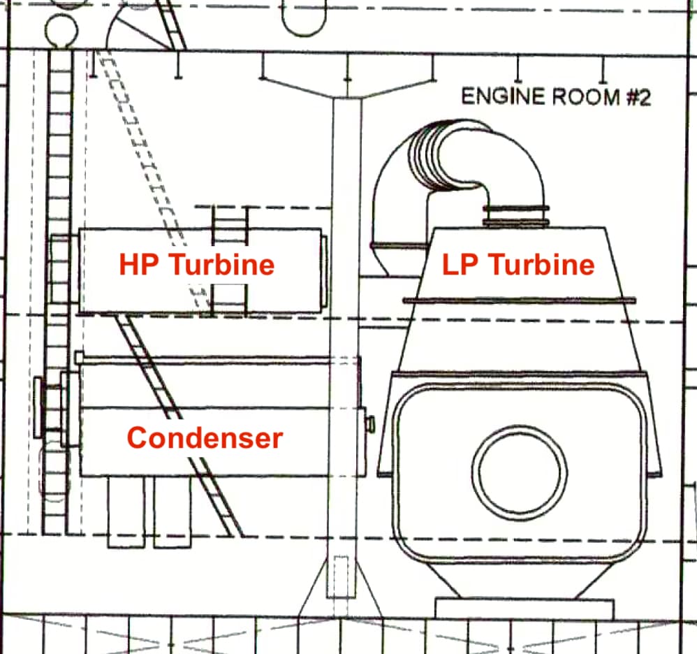
This view gives a good look at the size of the LP turbine.
This project won’t be started for a long time, and will be on a separate thread if and when I do, but I just wanted to give a teaser of what could come.