Awesome! Please let us know how it goes. Two tickets for that is a little too rich for my blood, my son wouldn’t be too happy if I went without him.
It’s too rich for my blood too. I’m getting comped due to the donations of the models I’m making to the ship. I’ve got about 1,000 work hours in the models so it’s probably worth something.
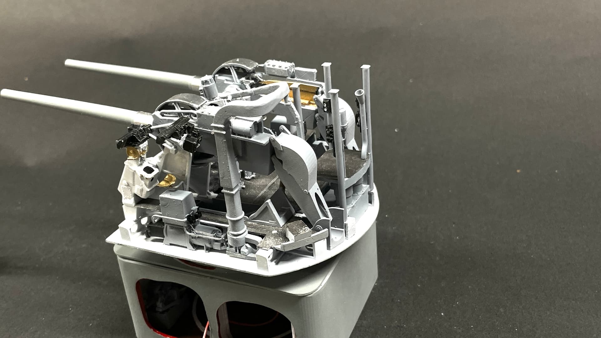
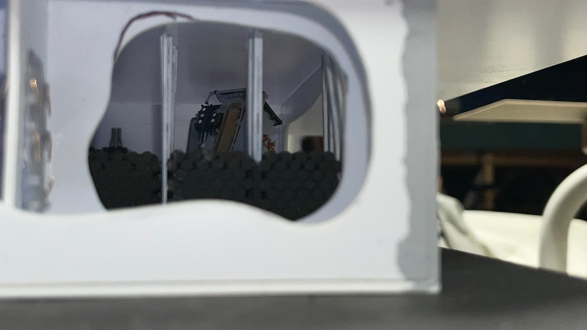
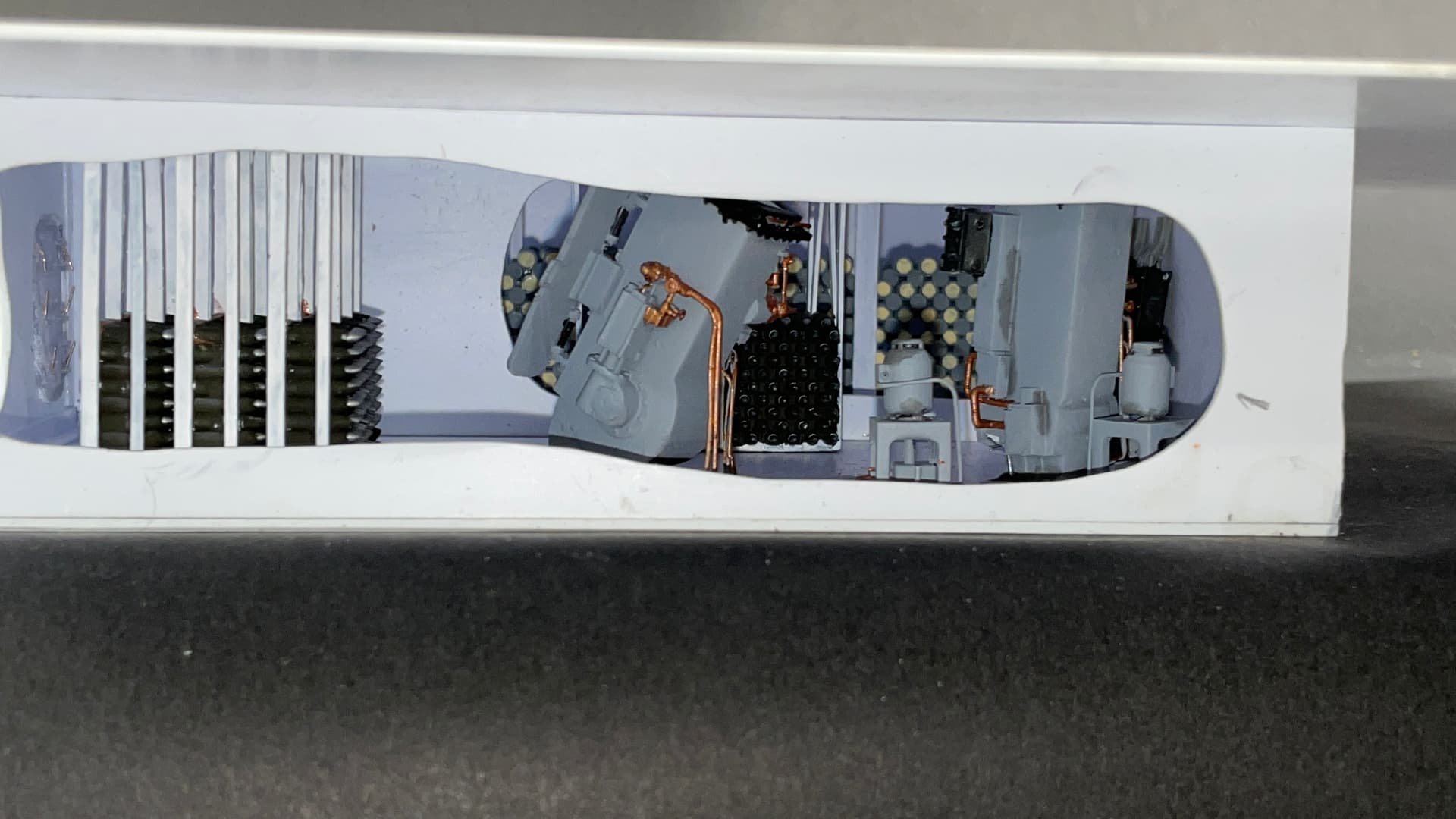
Sort of a milestone day… I pretty much finished all the gun house interior work. All that’s left is to drop the shield over top. That could be a nightmare, but I’m optimistic it will go okay (without breaking off any more foot rungs). There’s a lot of images today so bear with me.
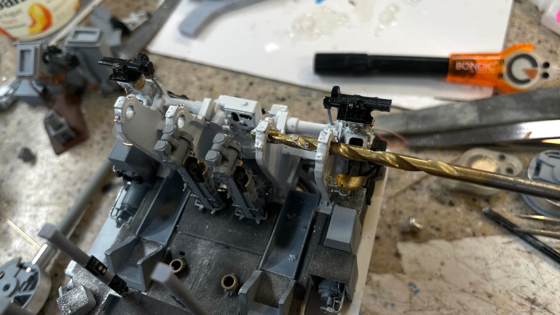
First thing I did was change out those 0015" pins holding the trunnion caps with 0.025" pins. I then drilled the holes in the gun receivers to let the aluminum turned trunions set down completely. They were sticking proud of the surface when I attempted assembling it yesterday. I then found that the trunnions needed too much pressure to insert due to cement and paint inside the bearings. I line bored the bearings to match the same openings in the guns and the pins fit perfectly. After assembling I put a little thin CA into the joint to both glue down the caps AND freeze the guns at the level position. They will not be movabable.
I painted the printed 5" powder cartridges and placed some in strategic locations. One is in the right gun’s load tray and two are protruding from the powder hoists outlets in the floor pan. I made a bunch more of them and might have them on the deck randomly as they would be in action.
I mounted the fuze setters control unit after inserting the right gun’s trunnion pin as I anticipated doing.
I added the oil filters on its support and both of the cartridge chutes that direct the hot, spent cartridges out the back door onto the deck behind the gun house.
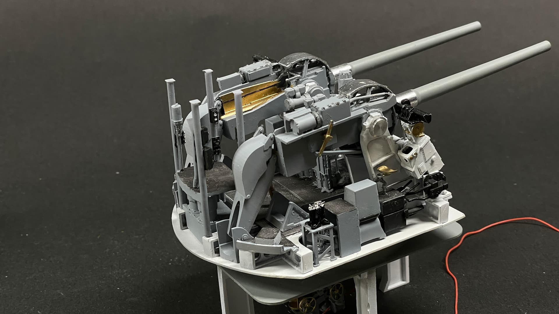
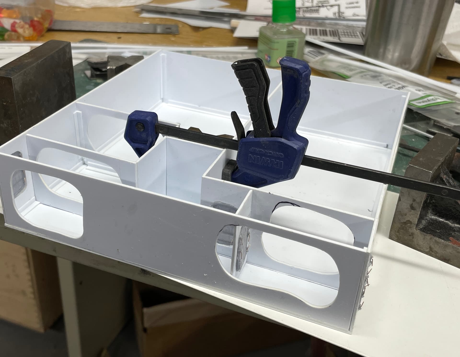
I then realized that there was no way at all that I was going to be able to drop the shield over the innerds AND STILL be able to get the ventialtion system installed properly. It wasn’t going to happen! I cut the vent unit off of the pipe that went through the ceiling girder and worked with it to install with the rest of the equipment. Even all opened up it wasn’t easy fitting it in. Still attached to the sheild assembly it would have been impossible.
I tried fitting the whole deal on the UHR and it will work okay. I’m still thinking about a way to use fasteners to hold the shield to the innerds since it would preclude having to clamp anything.
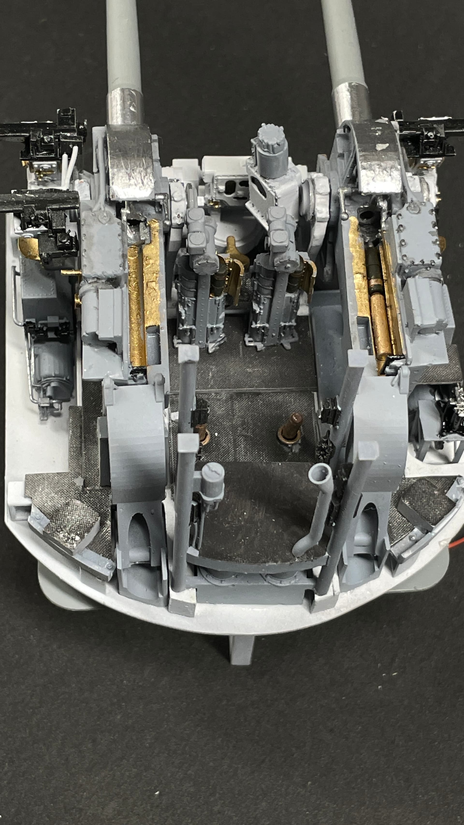
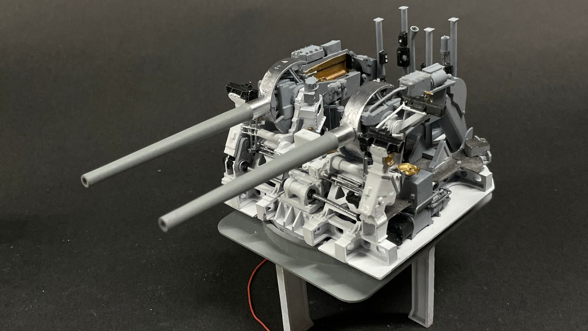
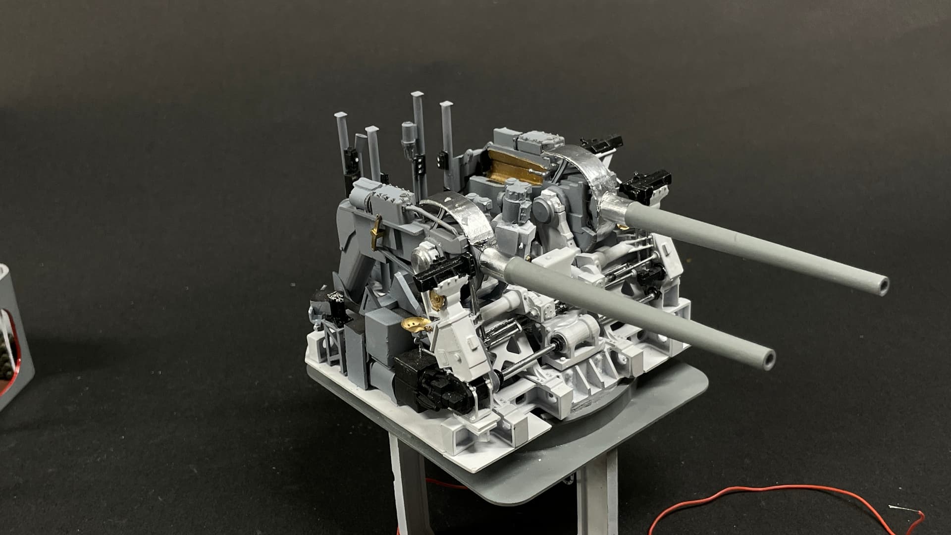
Here’s some frontal shots.
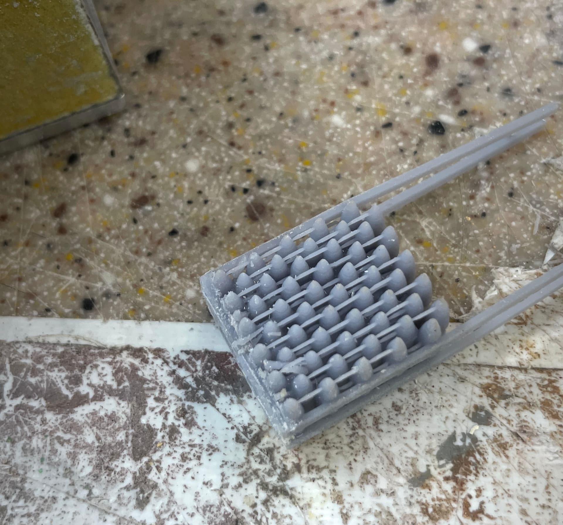
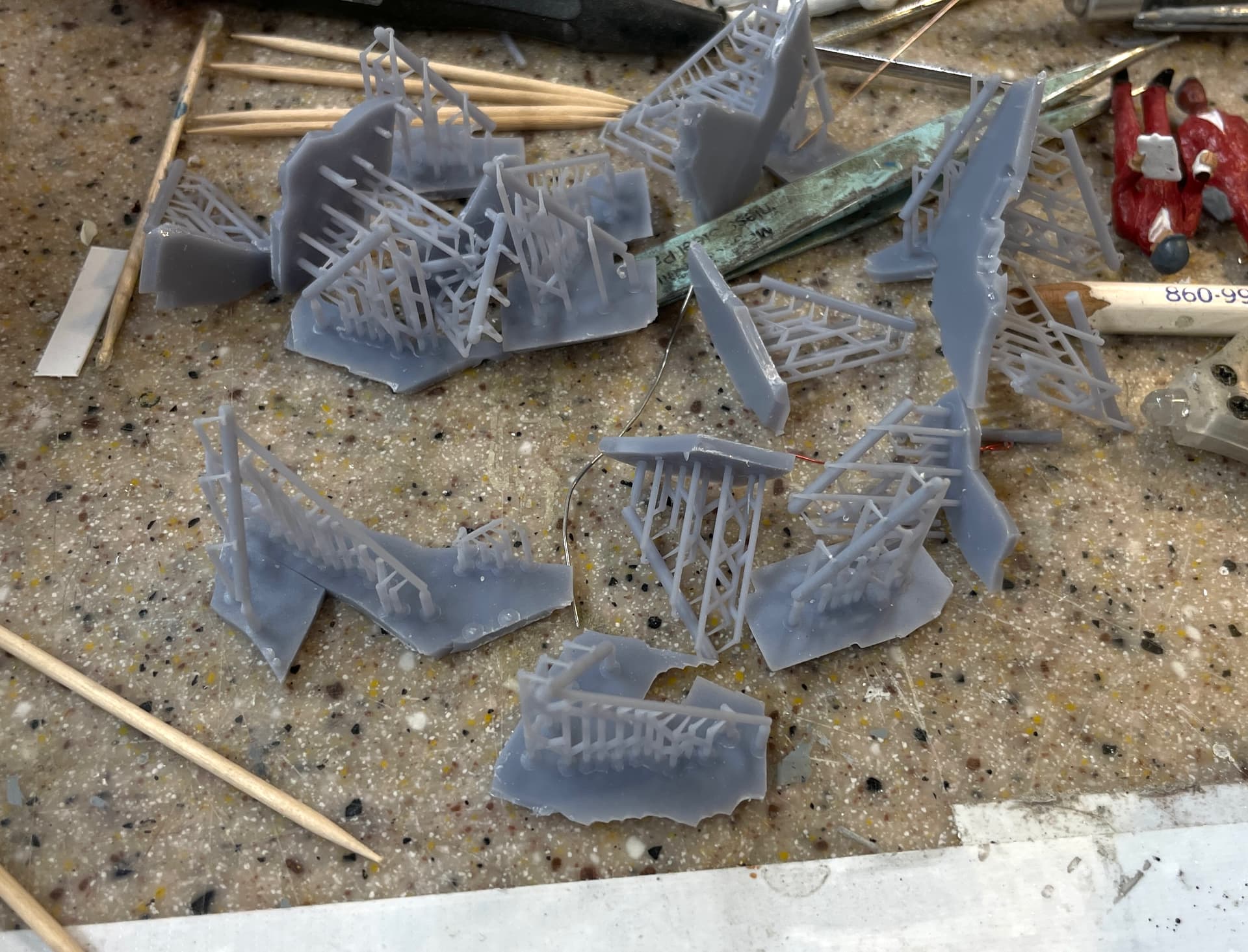
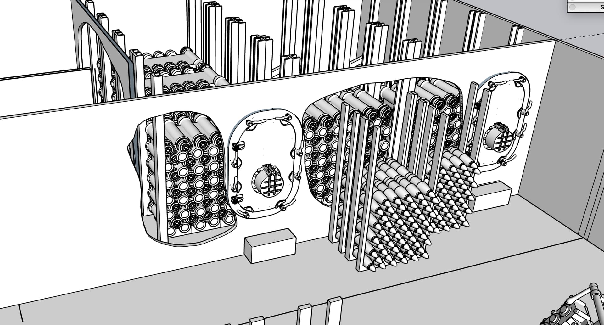
While these various parts were drying I was working on cleaning up pile of projectile racks for the magazine. I need 10 of them.
Because of the way I situated them in the printer, the slicer added a ton of tiny supports holding onto the tips of the projectiles which may not have printed well. It was a challenge to clean up and I’m not done yet. Meanwhile, the printer just finished the first batch of three powder container racks that go into the back room. I need five with ammo and four empty that will be in the background so you’ll only see their poles sicking up.

This shows all those tiny supports. For those that will be behind others removing them all may not be necessary. I got faster the more I did.
And those left to do.
I found some O’scale figures that I’m trying to populate the model. The scale is right, the garb is not. There are companies that make terrific figurines in this scale. I may get some. I can also kitbash some of these Woodland Scenics figures to make them WW2 US Navy sailors.

That’s all the work for this week. Y’all have a nice weekend. It’s finally going to stop raining so we’re going to get out of the house tomorrow.
10 Likes
Some odds and ends from yesterday’s and today’s sessions.
Continuing to print, cleanup and paint various components going into the magazine. By tomorrow all the printing for the model will be complete. While doing this, I’m writing the 3D printing book. It’s good to write it while I’m immersed in such a project. It’s keeping it real.
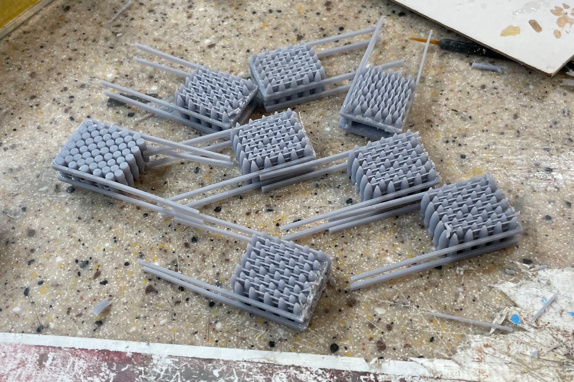
I’ve got all the powder cartridge racks printed. The enpty racks will be behind the vision line, but you’ll see the channels so viewers can assume there are canisters in them. Did that just to reduce the labor and resin use in making this part.
I painted the projectiles Olive Drab and will do detail painting tomorrow. I printed a plan view of the magazine to make sure I know how all these furnishings get installed.
There are 6 racks with canisters and four empty ones. Here are all six before any painting.
I painted a little detail I missed on the hoists. The upper trunk flange is black.
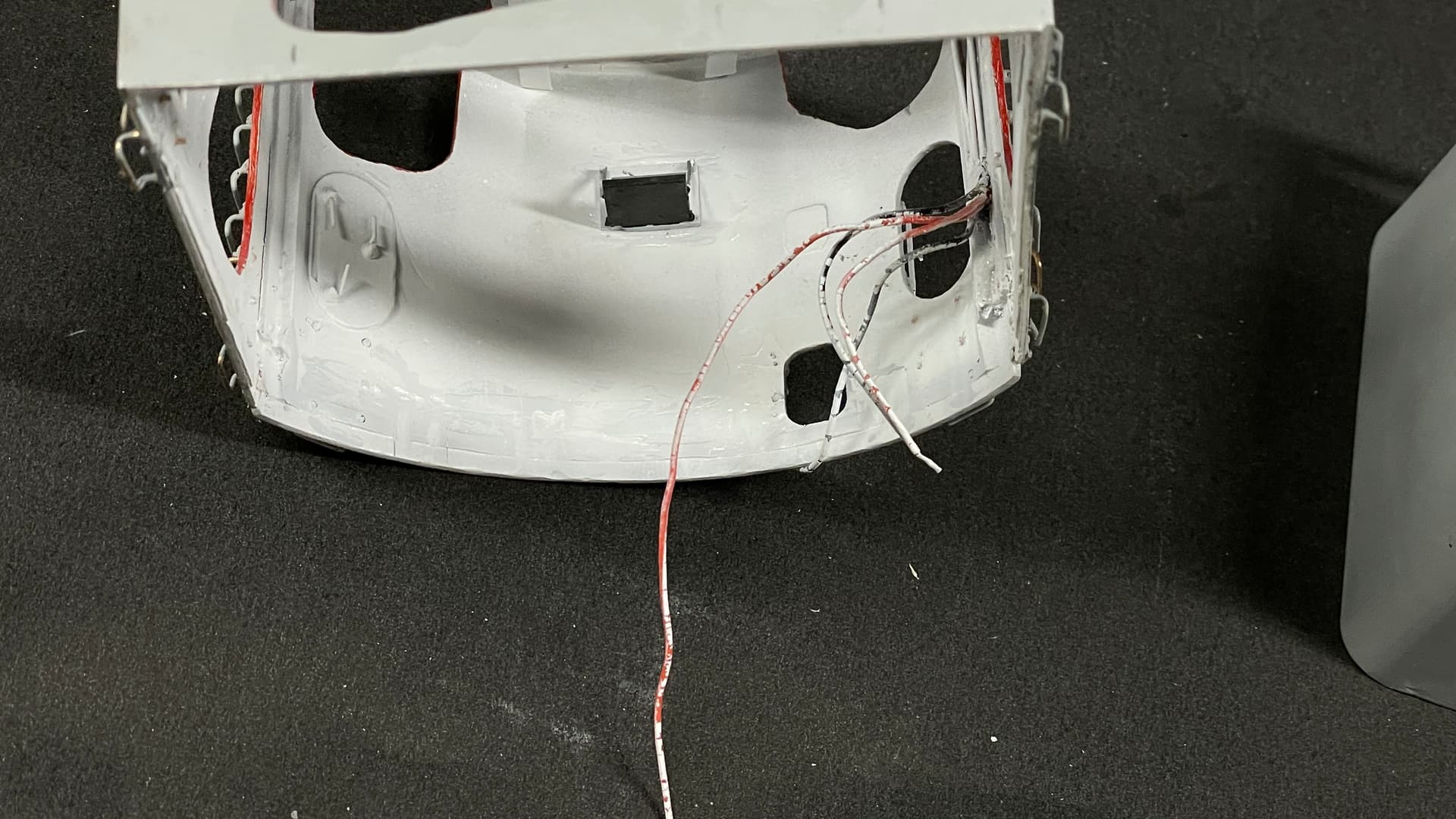
I also did a light check on the gun house shield. I’ve been tugging at those leads for a few weeks and wanted to make sure they were still viable. They were and they’re nice and bright. The white interior will reflect the light into the shadow regions.
I bumped the captain’s manual sight again and broke it again. I tried fixing it… again… but’s it’s a mess and no longer conforms to the model’s quality. I’m printing more of them. I also replaced another 5 broken foot rungs with phos-bronze. Hopefully this is the last of them. I’m getting pretty good at making and installing them, and that’s really a good thing. It means I keep breaking stuff. It’s like getting to know your body shop guy. It’s not somebody you’d like to know that well.
I’m going to remove the old one, but wait until the gun house is installed and safe before re-installing the new one. Again… benefits of designing and printing one’s own parts is you can make more when you screw them up.
I messaged with Ryan and we’re going to visit the ship on Sunday morning, May 19. We’ll be getting into Philly the day before. If we waited any longer the ship might be back in the water.
7 Likes
Hello!
It’s looking really good! I like your painting, too!
With those rungs - I kinda predicted they would break off, remember? With fiddly bits like these it really pays off to make them sturdy, although it’s hard most of the time. My friend who is converting railroad engine models always wanted to have all the fittings made out of metal and anchored because he said he knew he will handle those engines and wanted to avoid stress when something breaks off. I went the same way with my Piaggio model, where I made the antennae from copper sheet metal and guitar strings, to be able to handle the model with the antennae on while painting and decaling with SOME chance of them staying on the model. So far I only had to repair one…
Anyhow, good luck with your build and have a nice day!
Paweł
Thanks! Sometimes you fall into a 3D printing trap. While you really can almost print anything, physics and chemistry come into play and there may be other materials more suited to the task. With all the time I’ve wasted repairing and replacing them, I could have made them from metal in the first place.
For most of my working (and retirement) life, my most creative ideas happen just as I’m waking up in the morning.
For a while I’ve been trying to come up with a way to fasten the gun house shield to the base WITHOUT adhesive. It was an awkward fit and I really could see how to clamp it without damage. Speaking of damage, broke another 5 foot rungs and fixed them with metal. I was able to screw the 16" turret housing on by expoxying wood blocks in various locations using small brass wood screws. There didn’t seem to be any space to do that with this model. There was not vacant floor space!
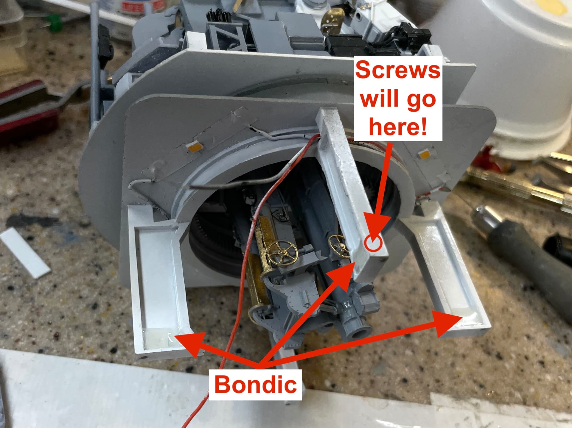
I was having one my normal, nutty dreams about making something or another that made no logical sensse, but as I woke I realized that I could fasten the housing to the frame beams just like the prototype. All I had to do was make them a little beefier to hold a screw. Then I brainstormed how to do that. I thought of wood, then J-B Weld, then epoxy putty like Milliputt, and finally Bondic. You can fill big spaces with Bondic. You just have to do it in multiple applications so you can effectively cure each layer with the UV light. All this noodling happened before I actually opened my eyes.
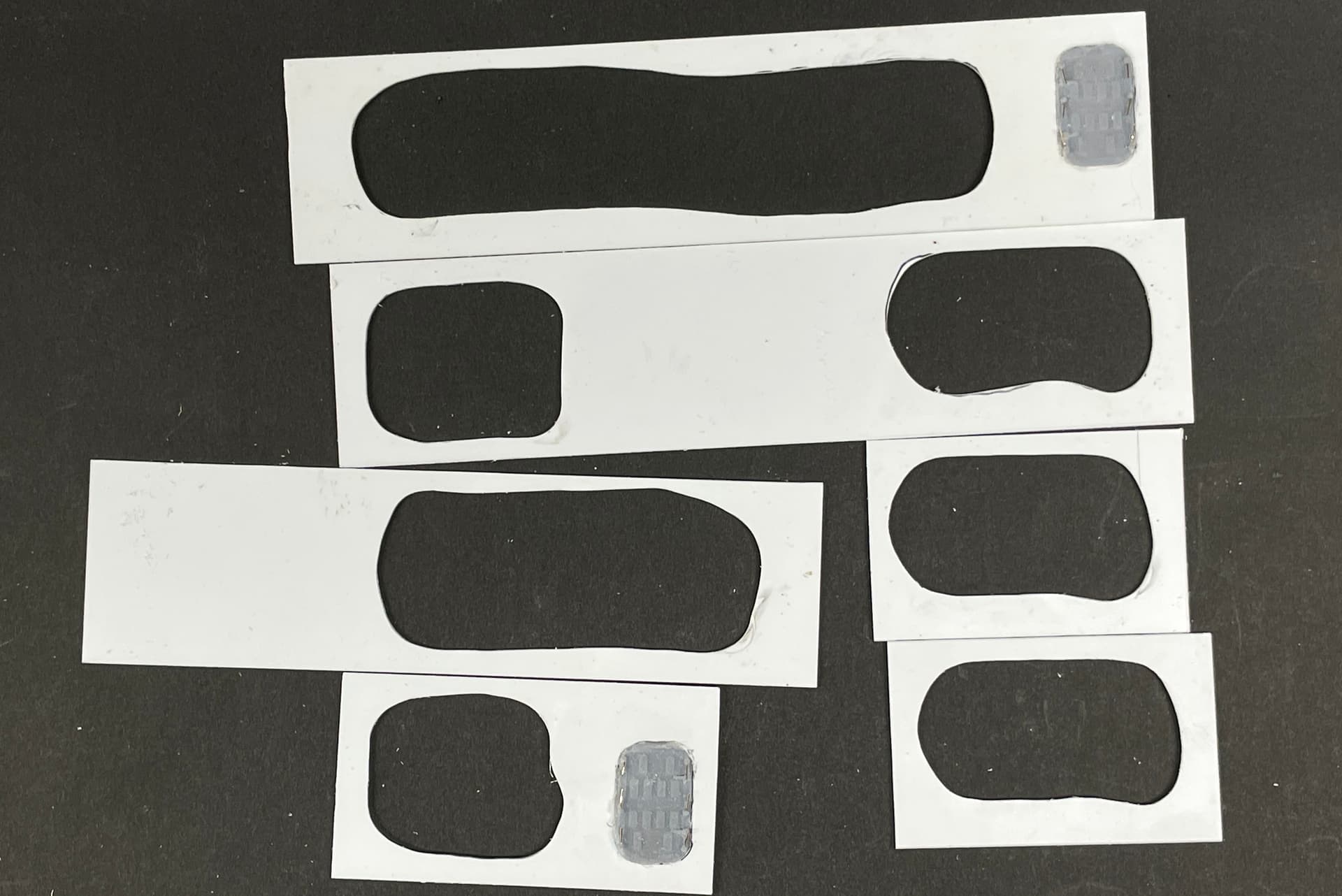
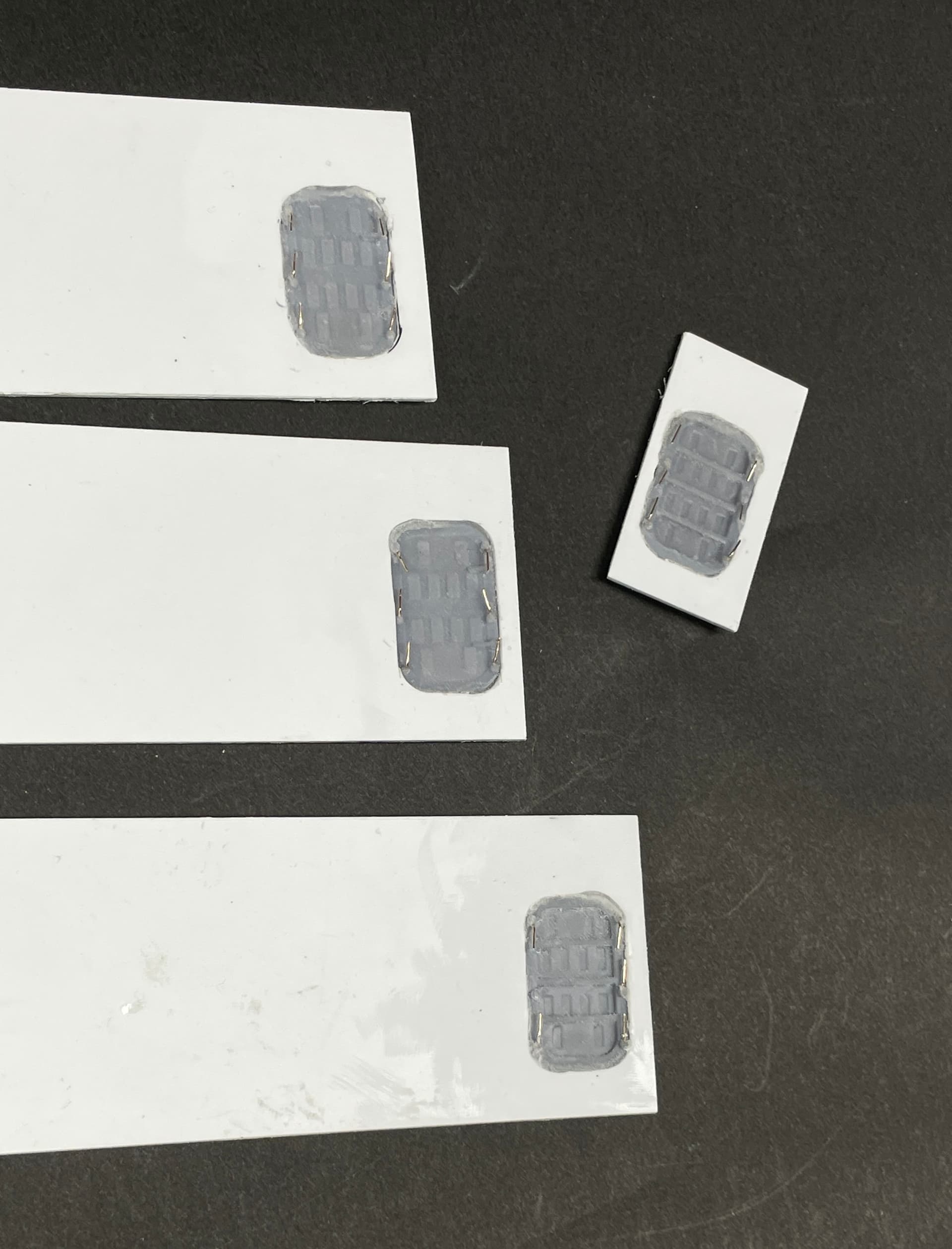
I also decided to try a test piece to see how well it would hold screws. I have some nice small ones that I wanted to use. I used a scrap base ring where I filled one of the bays between the ribs. The drill was a #58. The screw had a #55 diameter. I figured it would cut its own thread.
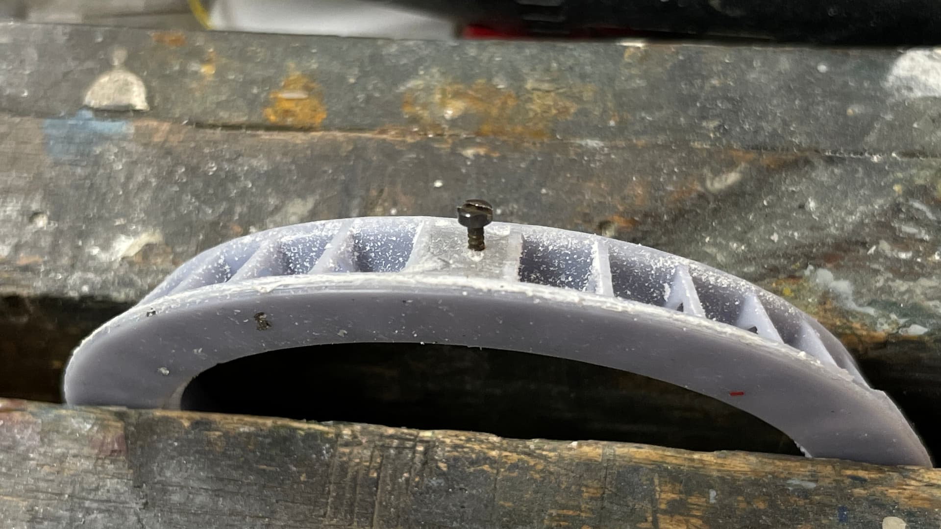
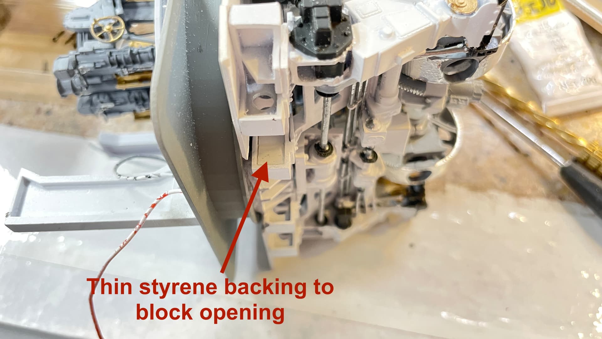
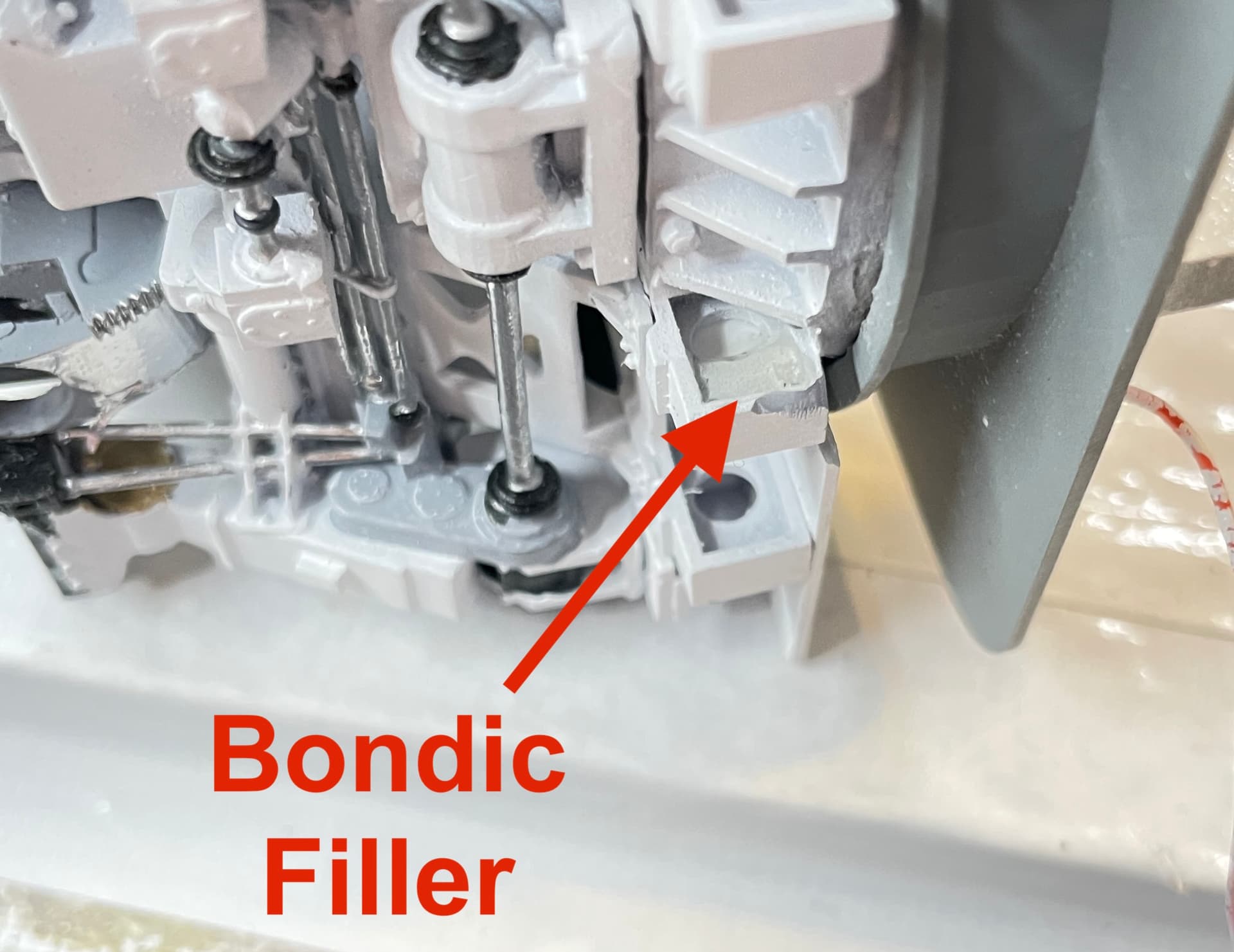
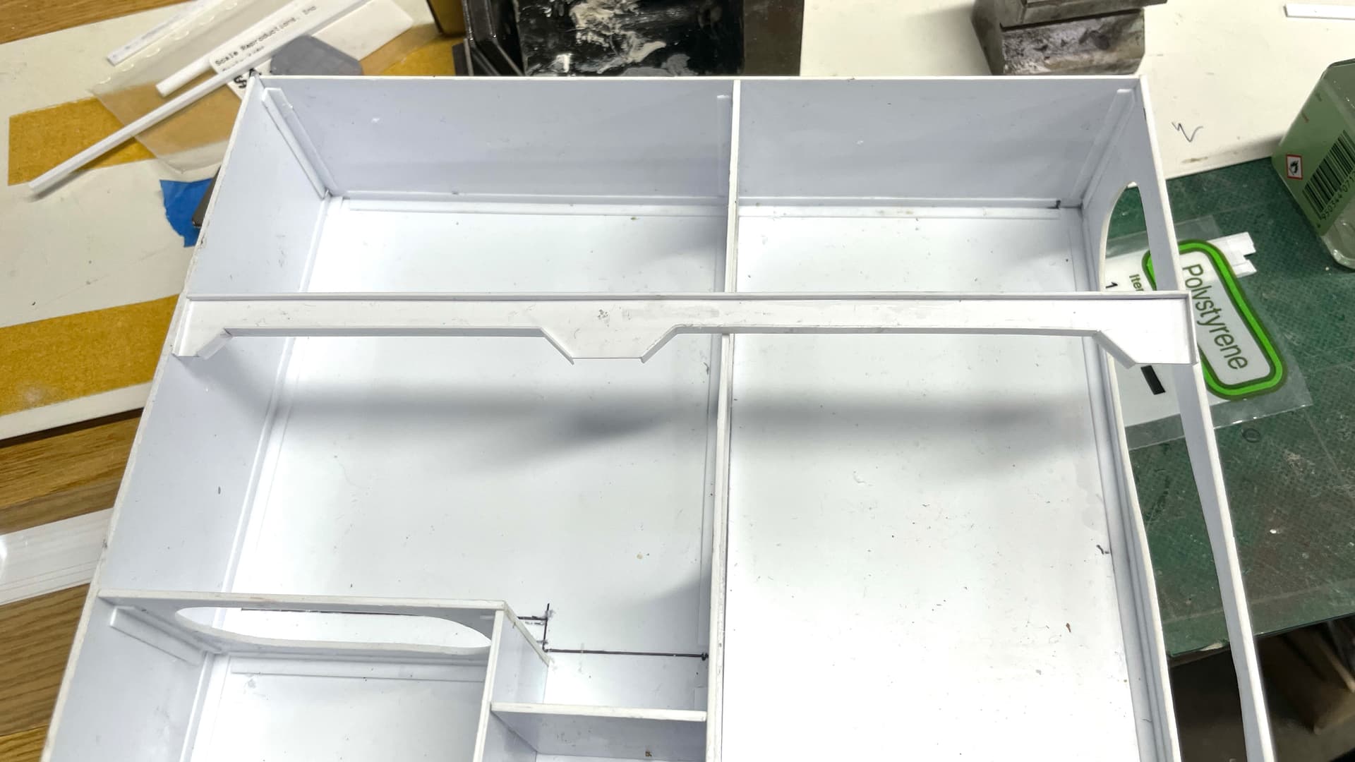
The Frame beams have those large lightening holes. I blocked them off with a small piece of thin styrene and then filled each side with Bondic until it was a solid. Since it’s exactly the same material as the beam, the drill should not wander.
This shows the blocking piece.
And with the Bondic filling.
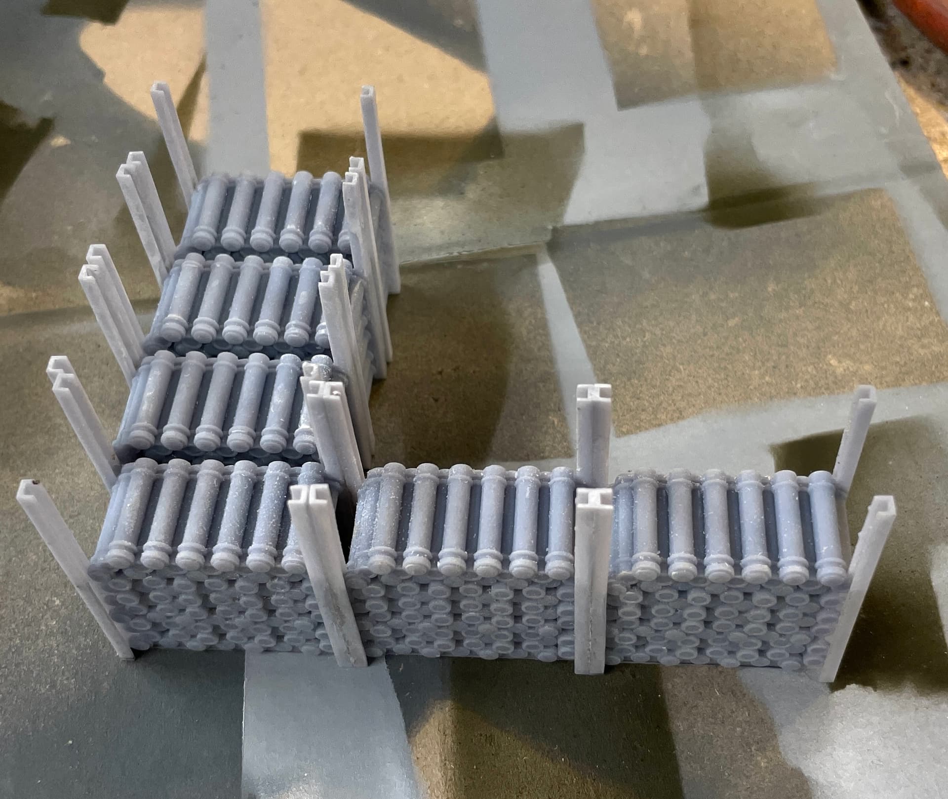
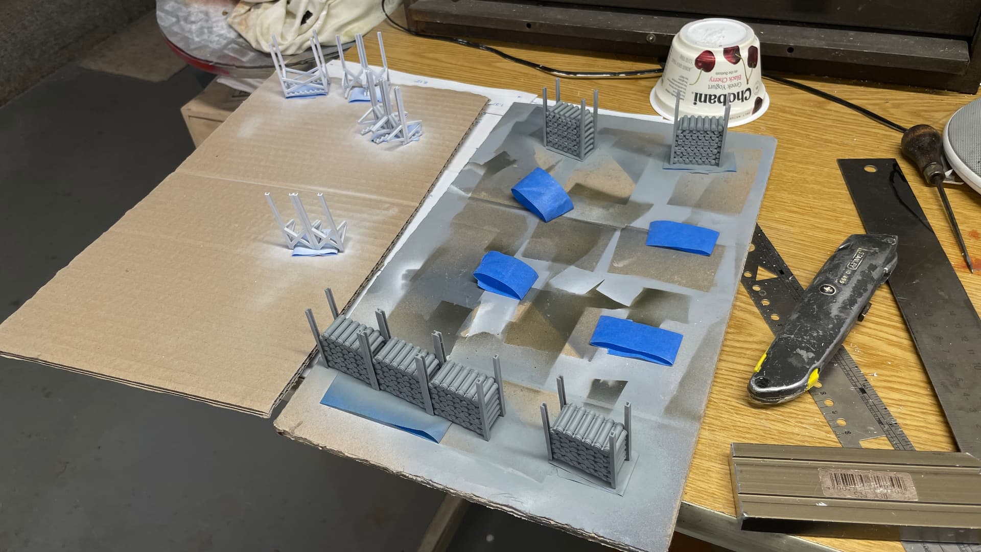
I airbrushed the first coats on all the powder racks for the Magazine: gloss white on the empty racks and haze gray on the full racks. Next session I will detail paint the full racks.
I got successful prints on the replacement captain’s sights, the magazine circuit panels and the portholes.
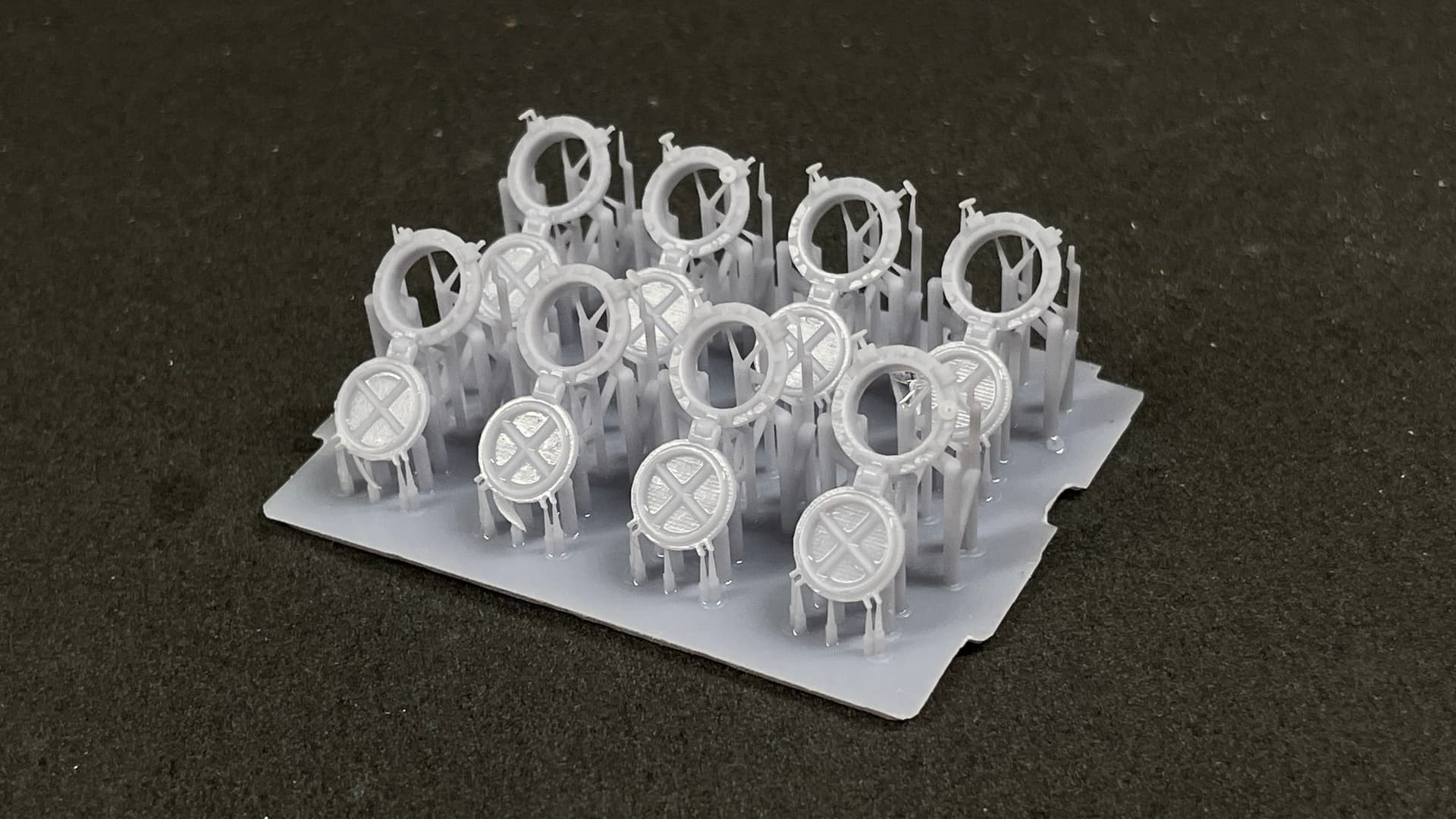
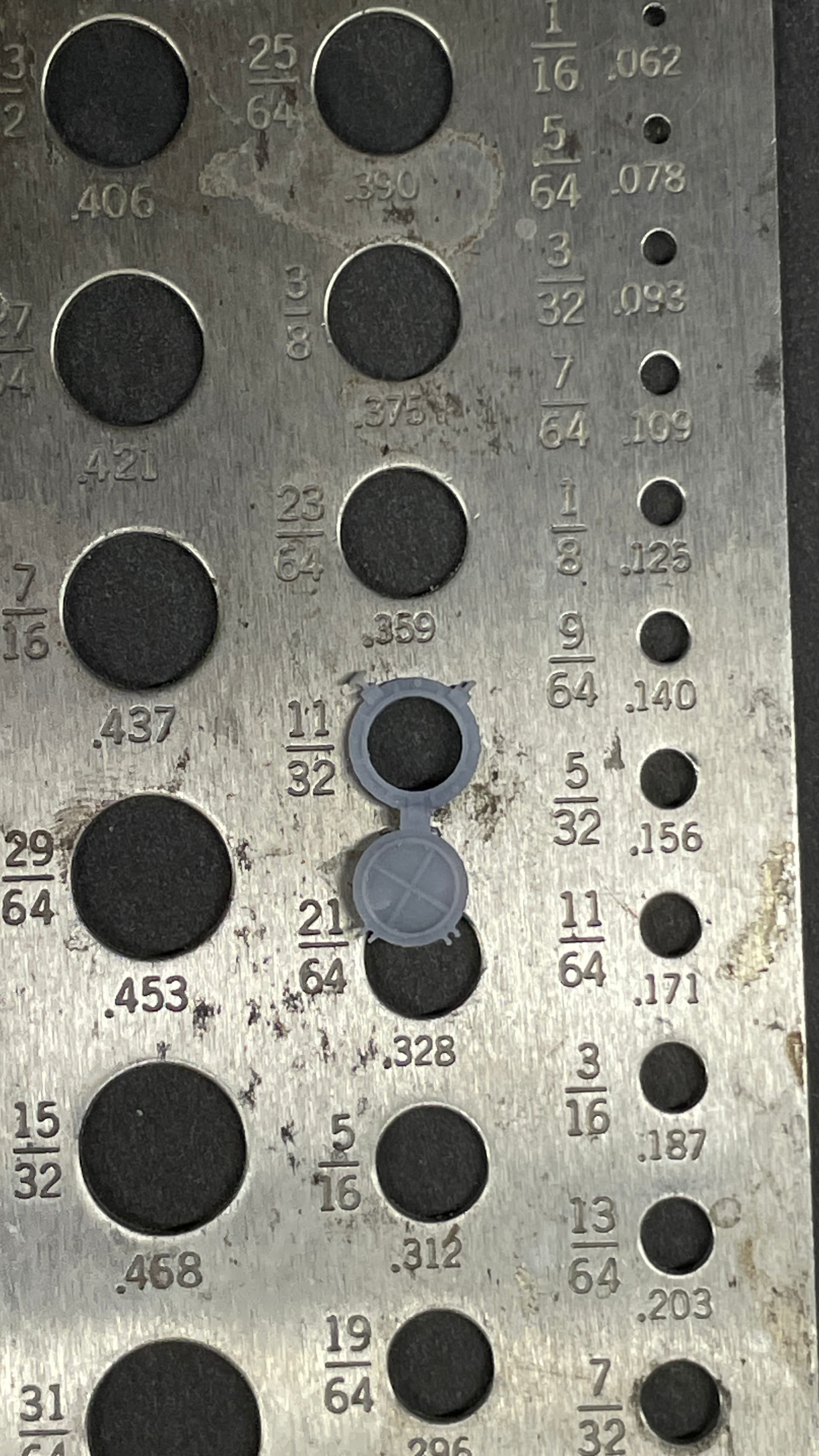
The portholes show the limit of just about what you can do with 3D Printing. Notice that some of the locking handwheels are already gone. There’s just not enough strength to hold up. The porthole fits into a 11/32" hole which will be drilled into the styrene bulkheads. The details inside face and that will be facing away from the viewer.
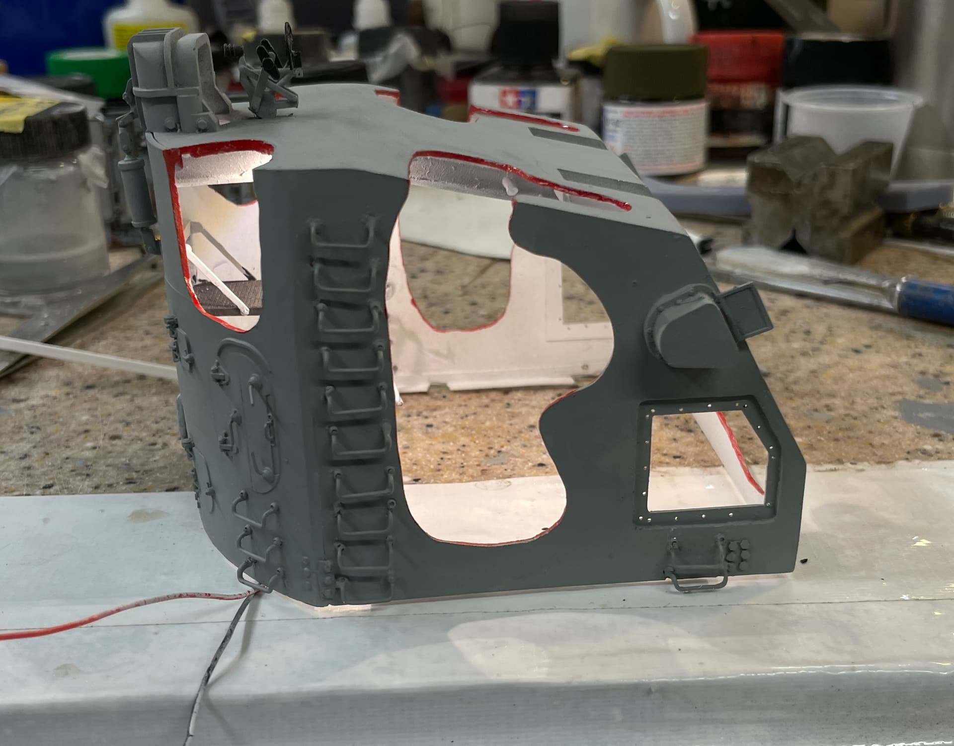
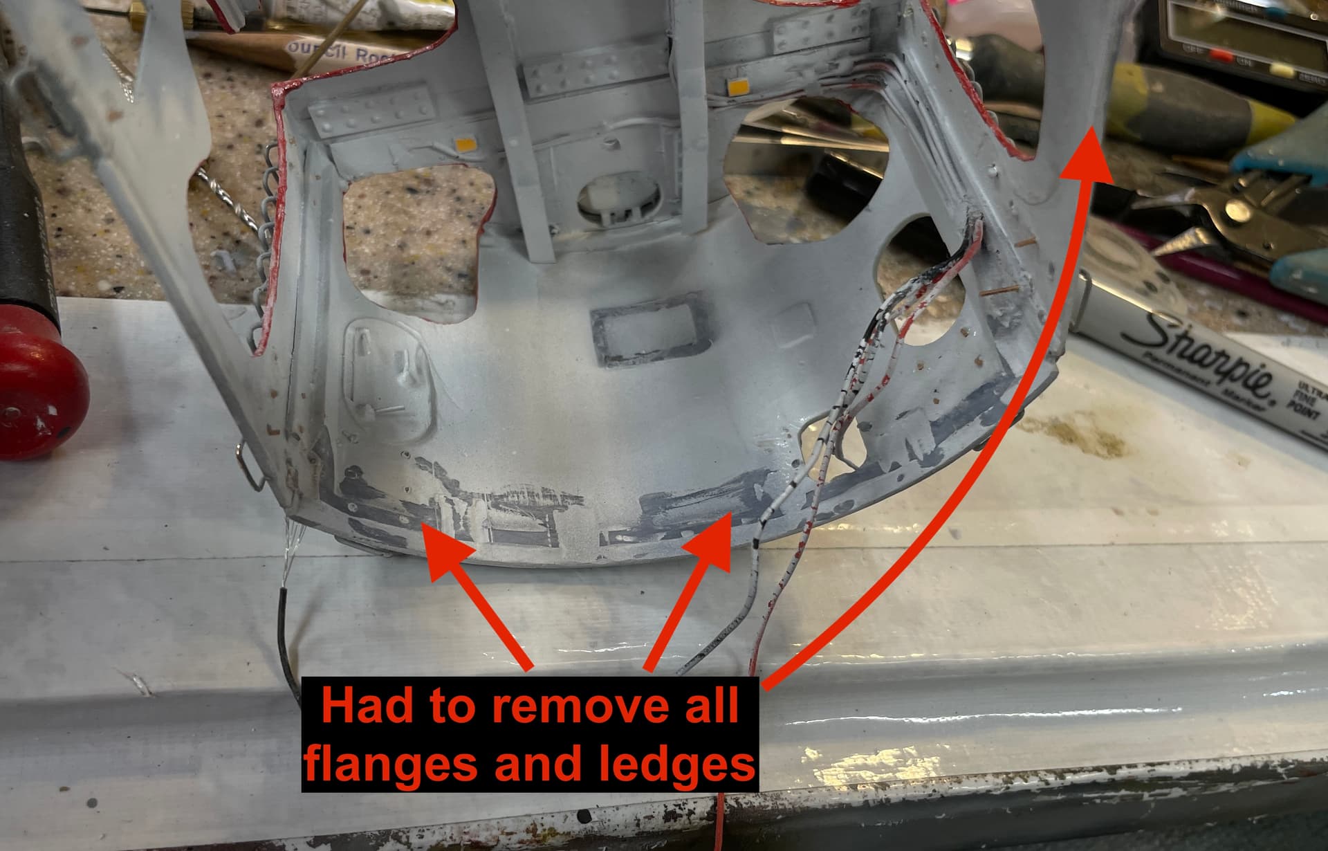
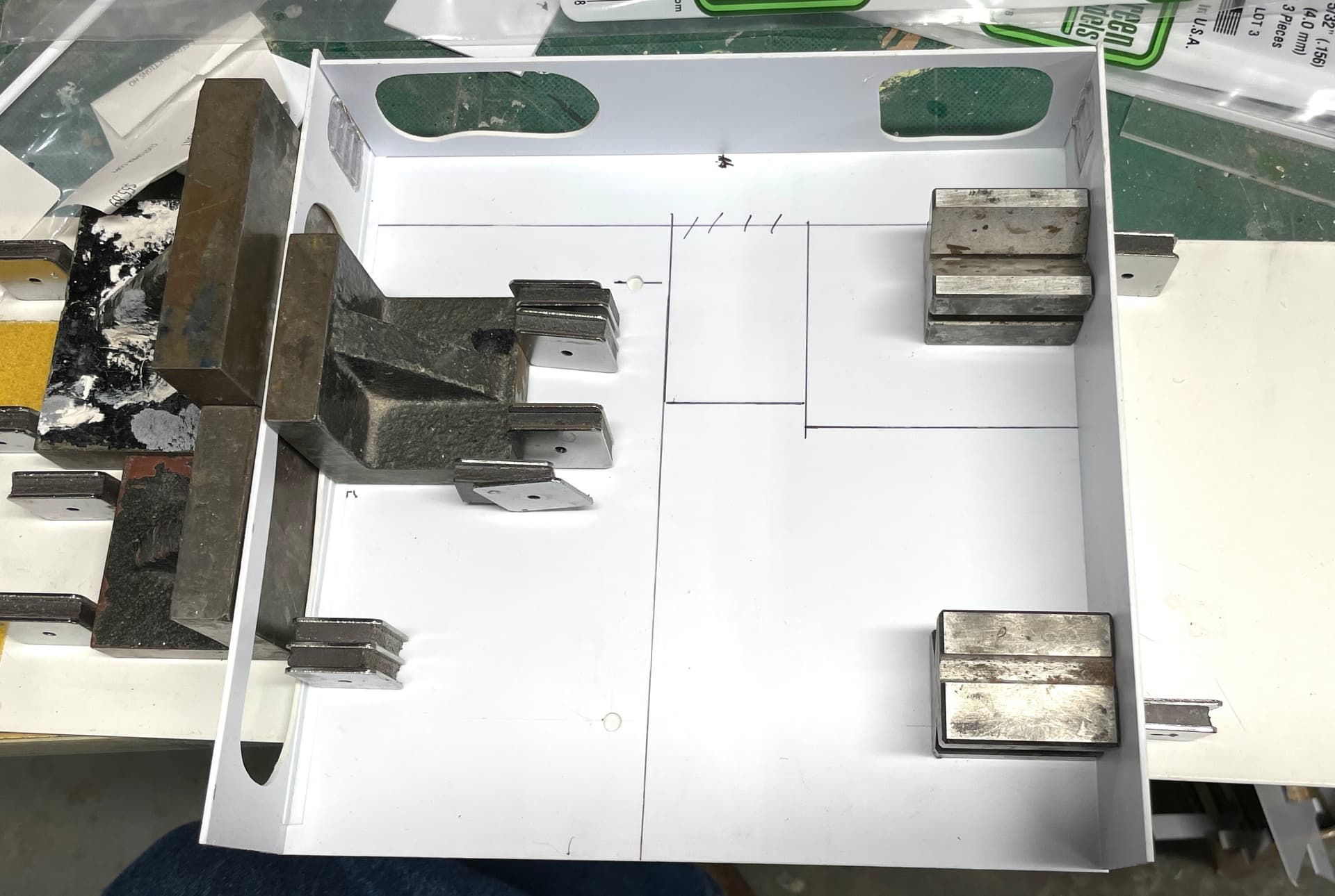
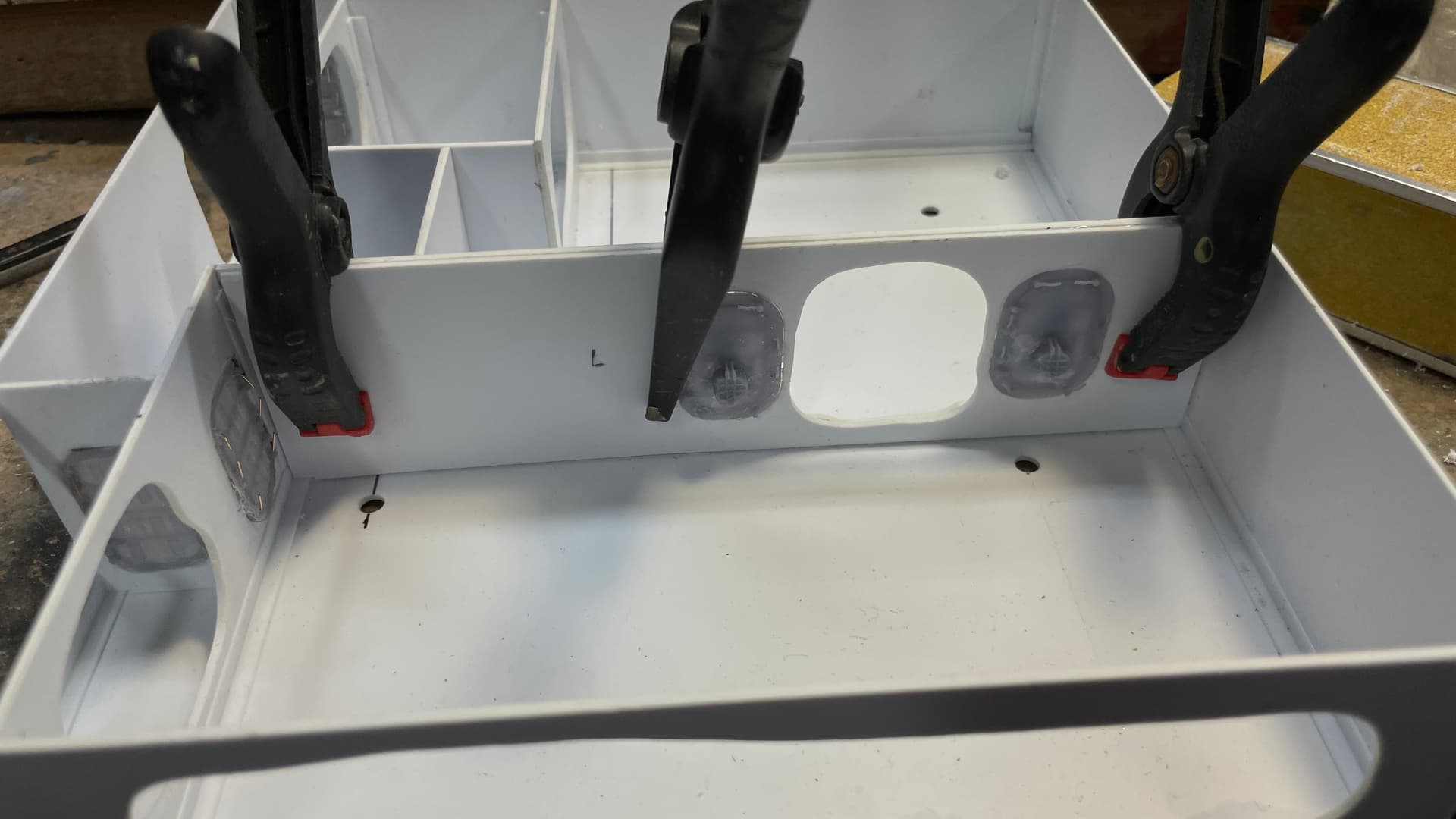
With the decision made on how to fasten the housing to the base, I now had to actually see how it fit. First of all, all the angles and ledges that I had either printed in or glued on were not working. They were hanging up on all the equipment, and they weren’t needed any longer. I cut/ground them off.
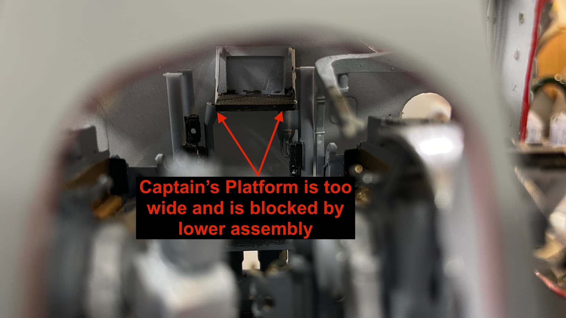
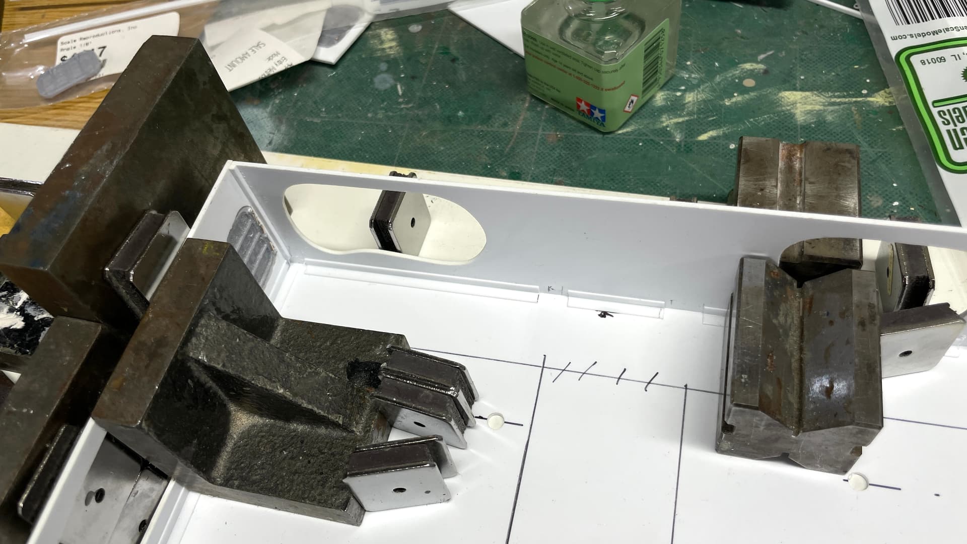
I got the front and sides to fit, but the rear was hanging up. Upon inspection I found that the captain’s platform was too wide and was not letting the housing drop down pass the voice tube and a control switch on the communications installation. If you look closely at this picture you can see it hanging up on them.
The correct fix was to redraw/reprint this part with a different width. I close the lazy approach (which turned out not to be at all), and found another spare and attempted to cut it down and remake the locking arms. Almost got it. The first arm construction went well, but the second one didn’t. It almost fit and in attempting to do a minor adjustment broke the part, reguled it and broke it again. It was scrap. I just redrew a revision and will print it tomorrow. My mistake was the platform fit when it was in its final position, but I didn’t account that it had to slide down through the obstructions to get it there.
With my resistance soldering unit I could actually solder the wire while it was in the resin part without damaging it.
7 Likes
Superb detailing.
Thank you!
The reprinted parts including the platform are done and painted. I cleaned up the gun house shield back wall and airbrushed fresh white on it so it’s ready for the newly resized part. Painted the white rail portions of the ammo racks waiting for the final touch up, and continued cutting out the styrene wall panels for the cabin work. So in summary, work proceed apace.
Making a new manual sight was the correct thing to do and takes advantage of having the 3D printing capacity right in the shop. The old one was just a mess and didn’t belong on the model.
I tested the new platform and it slips between the comm poles without interference so the gun house can be joined to the inerds whenever I want to do it.
All the white paint is on the ammo racks. I have to do some detail and touchup on these and they’re ready to go.
Woke up thinking about lighting scheme for the magazine and how to best run all the wiring to the electrical compartment under the wood base. There is a railing on the deck in front of the gun and I may add that along with the planked wood decking. I need more information about exactly how those rails were constructed. I will just need a little bit of it, so I could make the stanchions out of brass… much stronger than 3D printed resin.
All depends on how much time I have. I want to deliver the model when we do our visit on May 19. That sets a hard date. It’s not easy for us to make the trip back East, so if I don’t deliver it then it will have to wait until 3 months or more later. I don’t like keeping finished commission models around. Once they’re done, I want them out of my hands. I don’t want anything to happen to them.
I have to get the final case dimensions and order the plexiglass and the name plate. I also have to create the AV program. I’m collecting images as I go along for it so the work will be in organization and adding all the text items. Shouldn’t take too long, but it’s another task that’s needs to be completed.
4 Likes
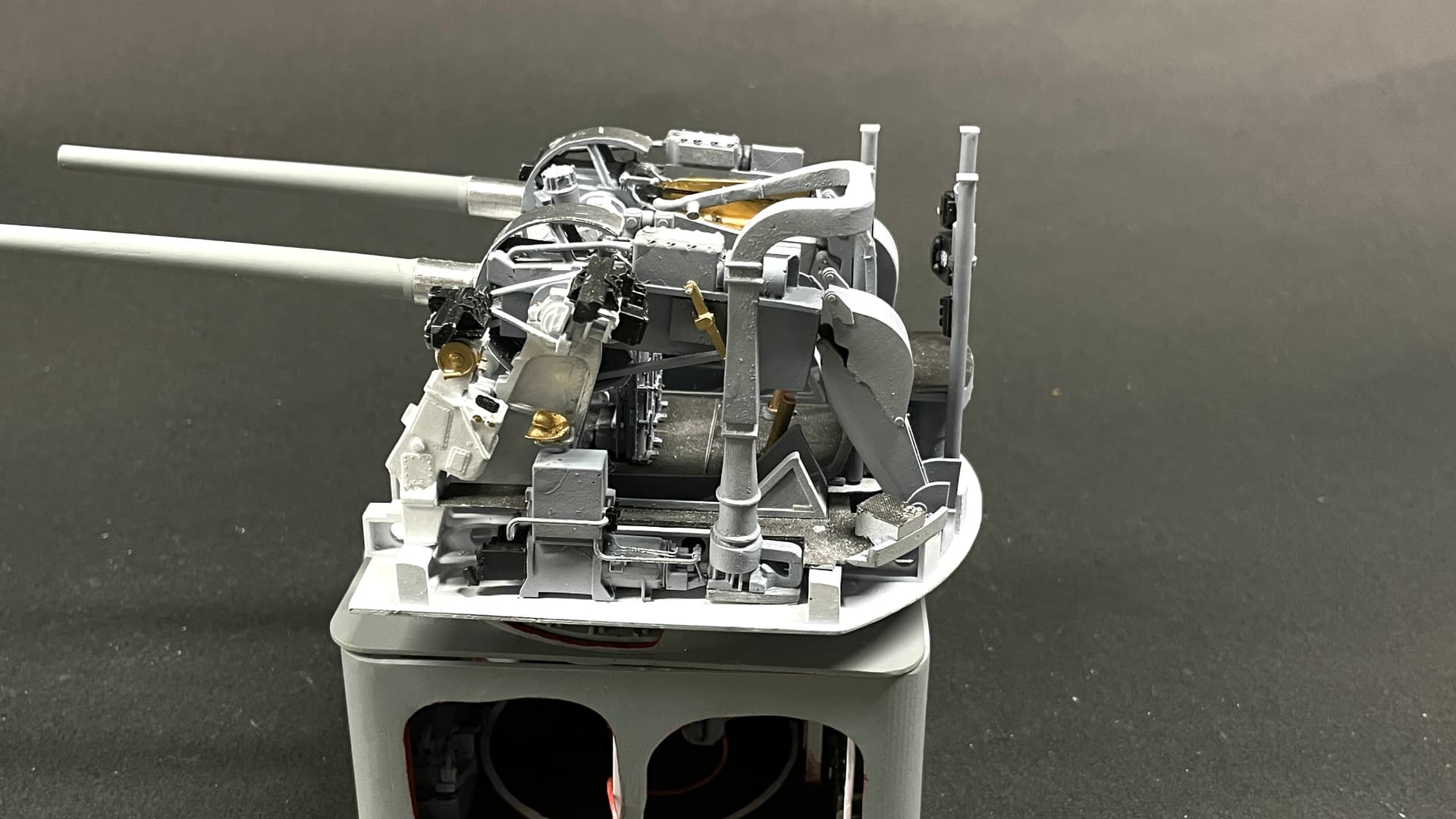
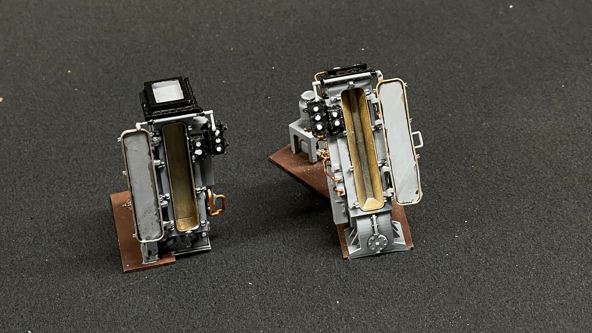
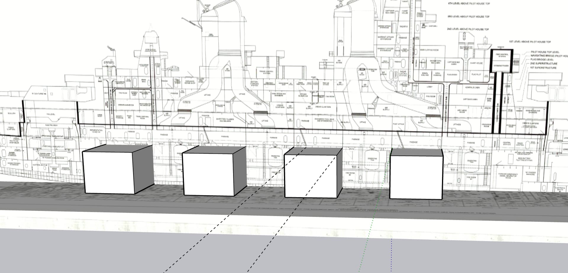
With the 5"38 project showing signs of completion, I’m starting to think about the engine room challenge. To get 33 knots, over 250 feet of the entire center of the Iowas were dedicated to propulsion. Each of the four engine rooms generated 53,000 hp. The engines rooms were over 35’ feet long, over 60’ wide and 25’ high. In 1:48 the model’s volume would be 7.8" long, 16.5" wide and 6.5" high. It’s not vastly large. I have general understanding of the layout, but that’s insufficient. The machinery takes up two platforms vertically, with floor gratings separating the levels. I am not planning on modeling the boilers, but may change my mind.
Here’s the four engine rooms withing the envelope of the armored citadel.
I’m aiming at engine room #3 since it was a rectangluar shape with square corners. Rooms #1 & #2 had tapered sides based on the curvature of the hull.
This is the floor plan of #3 from the 1st Platform level. There is the 2nd Platform level where part of this extends downward to. The low pressure turbine is very large and extends downward. The condensors are also very large and are at the lower level.
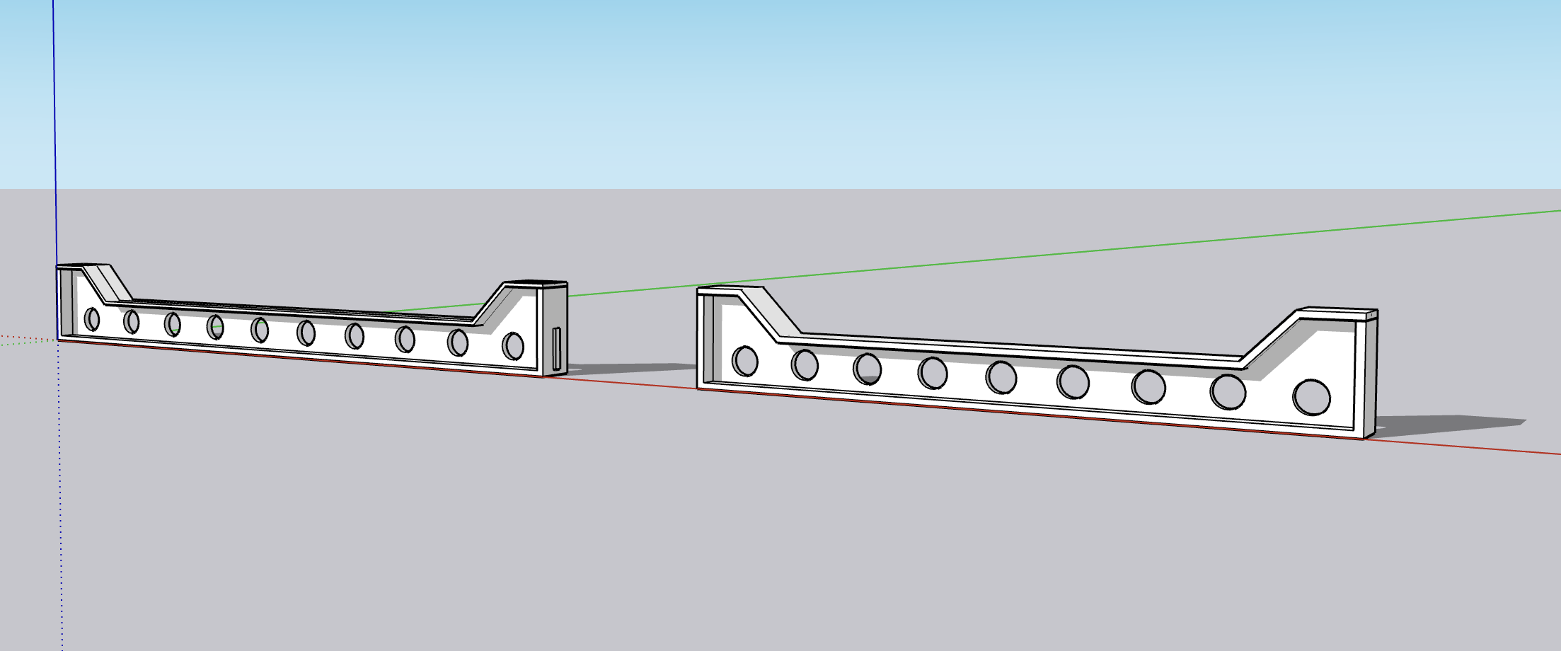
Elevation views of two rooms show equipment from different points of view. I was wondering how the 53,000 hp thrust is captured and transmitted into the ship’s structure. It’s not a simple thing. The prop thrust is captured by the all-important thrust bearing, but where does it go from there. I am assuming that the massive vertical beam that’s attached to the ship’s structure by massive gusset plates is where the thrust enters into the ship proper and propels it forward.
This view gives a good look at the size of the LP turbine.
This project won’t be started for a long time, and will be on a separate thread if and when I do, but I just wanted to give a teaser of what could come.
8 Likes
That will be pretty impressive
1 Like
Careful, you may end up building the whole ship . Amazing work ! I’m hoping to get down to the navy yard this weekend or next to see her but in the meantime found this sat. view
1 Like
That was a neat site. Thank you! If you’re planning on visiting the inside of the ship, it’s off-limits to the public due to all the safety stuff is turned off. Visiting the ship in dry dock is only available on weekends and for the down in the bottom tour is not inexpensive and almost booked up. You may have to wait until it’s back home at the Camden Waterfront.
Yesterday’s work and today’s are in this post. Bunch of odds and ends. Got all the ammo finish painted and ready to install. Mounted the new captain’s platform installed and it works. The gun housing drops right in place. Continue working on the styrene sheet stock cutting the partitions for the magazine. I somehow lost the cut ends of the sighting telescopes which I wanted to glue into the sighting blisters. I took the drawing of same and made a clipped off versions. I’ll print them tommorow. Once they’re finshed I’ll glue them in. Then the housing will be ready to install with the scews.
Speaking of screws; I decided that if it would work to hold the gun house together, why not do the same on the UHR. To that end I added Bondic filler to the bottoms of the four legs of the ring frame. The screws should hold it down nicely, and again, I’ll be able to take it apart should the need arise.
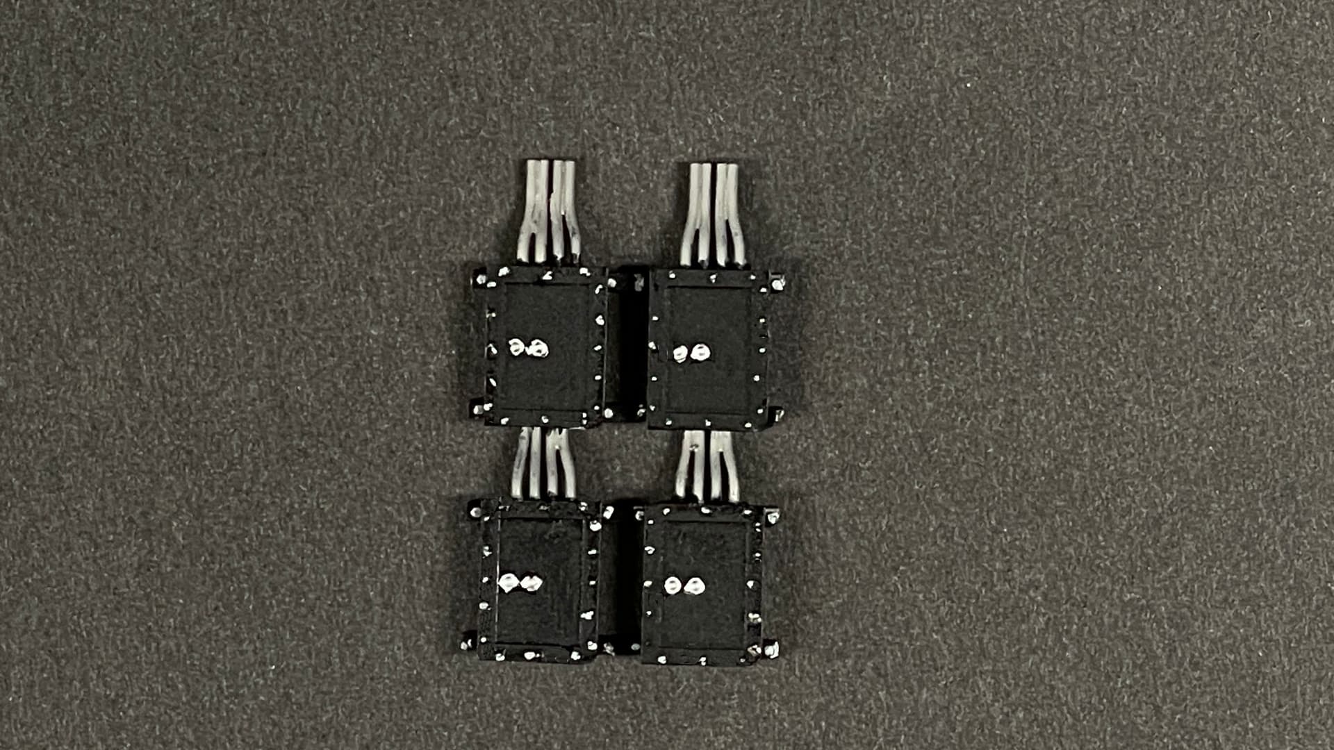
I power my LEDs with the CL2N3 LED drivers soldered into a small circuit board. When I was doing this for the 16" project my first attempt had their polarity reversed. I soldered together another one. That “bad” one was sitting on my bench since them. Today I successfuly de-soldered and removed them. They all survived the ordeal when I tested each one. They’re not that expensive, but they’re not free either. I will use them again.
I finished painting the magazine circuit panels.
Here’s the new platform glued into the rear of the gun house shield.
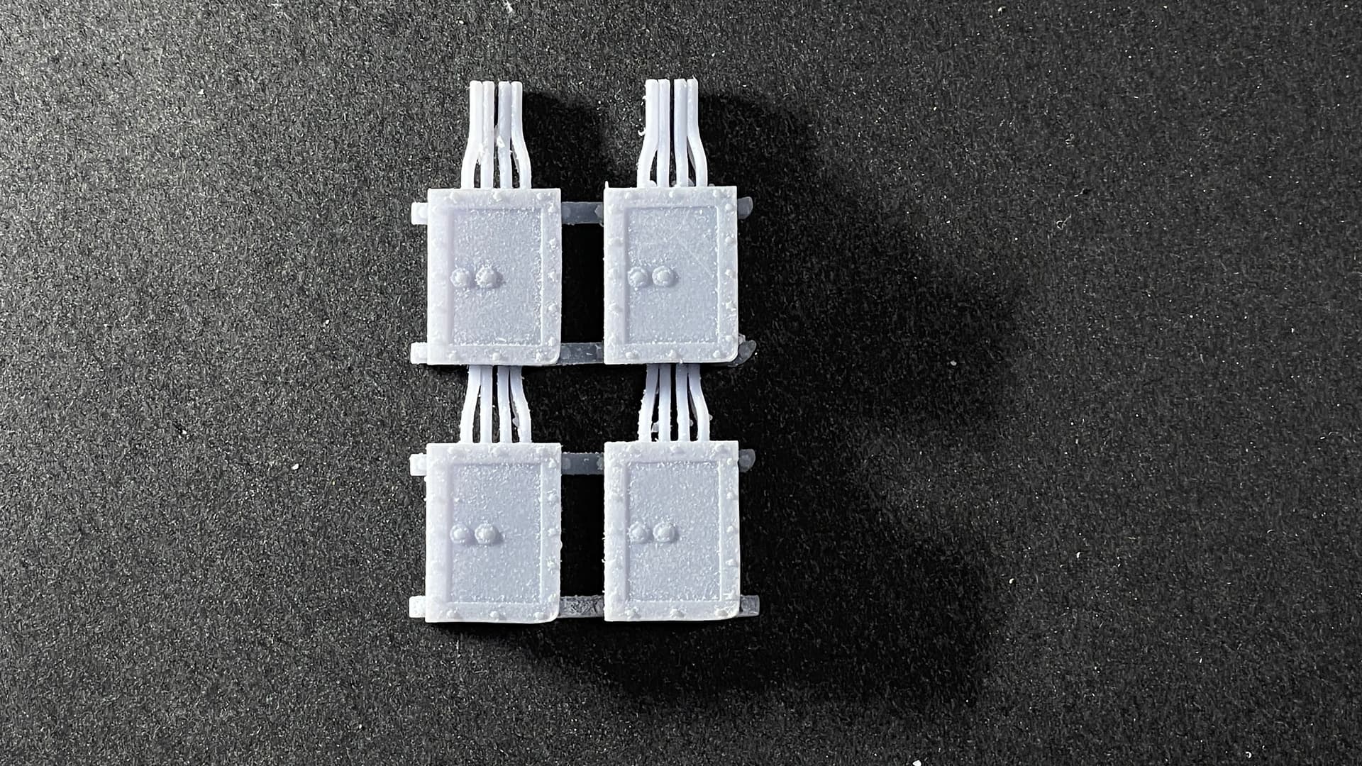
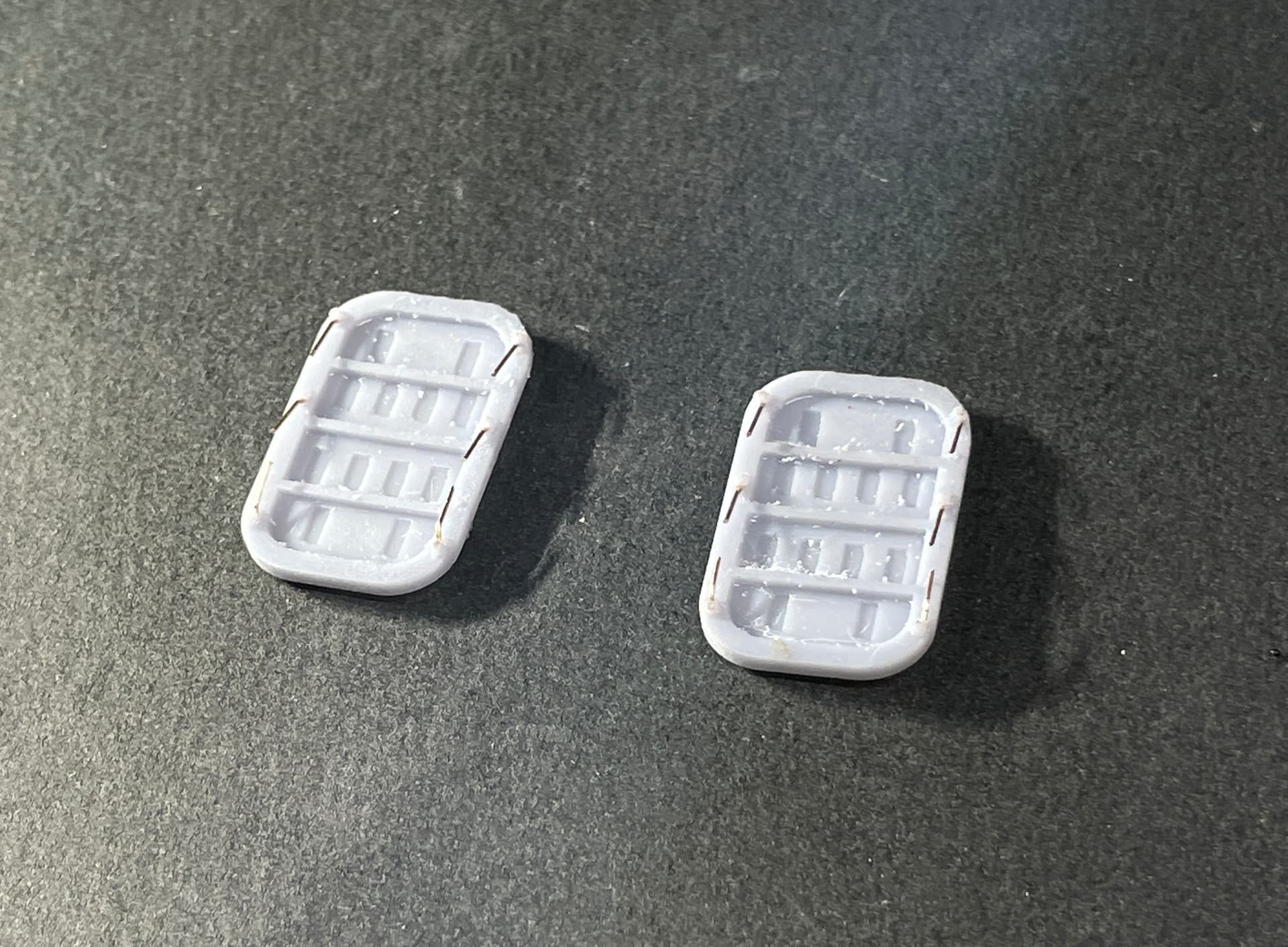
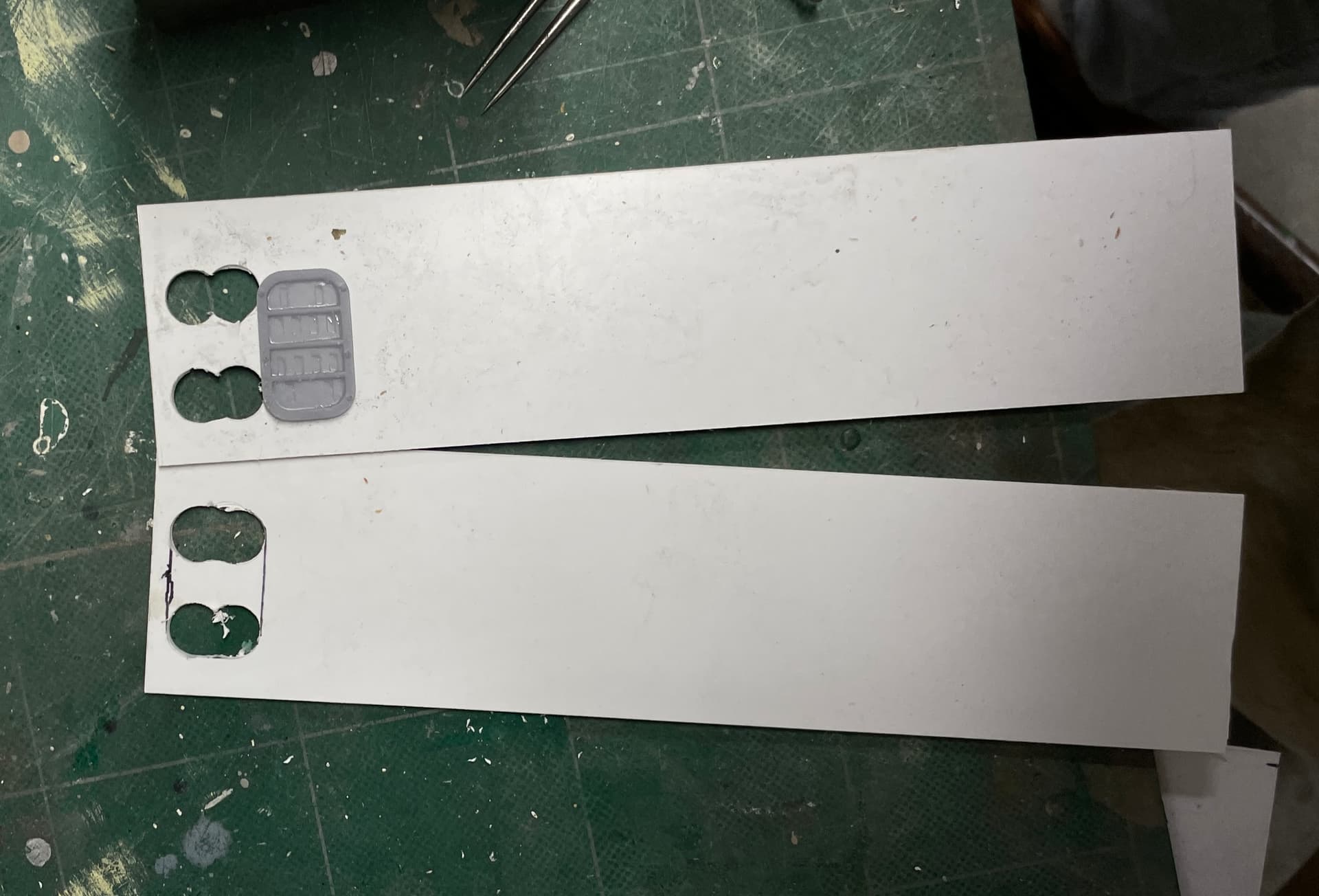
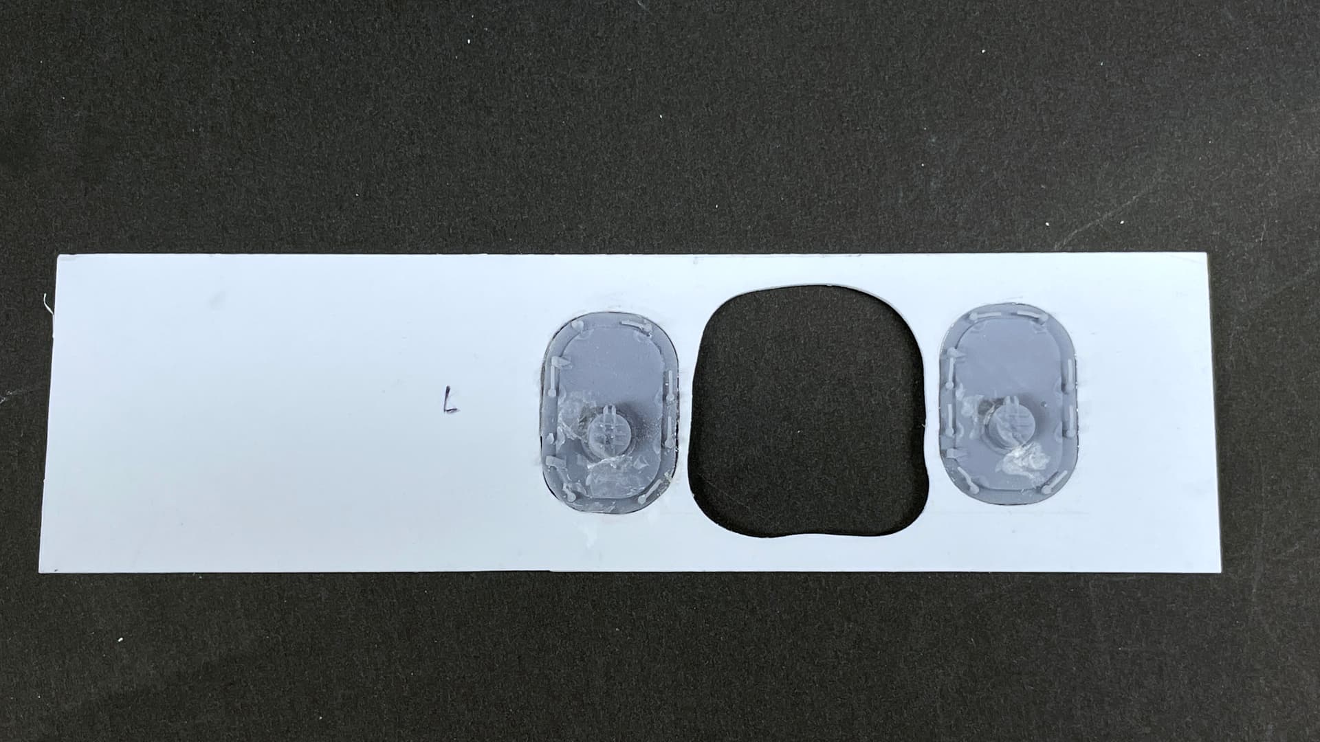
I drew and printed the correctly sized magazine entry doors. On the magazine’s outboard side is a narrow passage. On the port side (towards mid-ships) is “Broadway”, the 300 foot long wide corridor that goes from turret #2 to #3 and has entry to all the magazines, four boiler and four engine rooms. The view of my model will be from outboard looking in.
I didnt even attempt to 3D print the door dog handles knowing now that most would break off. I did made a tiny hole in the drawing whcih the print did pick up as a guide for the drill. I used phos-bronze wire (0.015") for these handles. I did not put them on the non-viisible side.
I’ve started cutting all the walls beginning with the magazine. I’m using a fairly heavy stock for these walls thinking (probably wrong) that the magazine’s walls would be thicker than you’re average partitiion. Still don’t know about the ceiling detail, but have an idea of how to do the roof girders.

Lastly, I got more serious about how to run the wiring and did those Bondic thickening areas to prepare to accept the screws at the bottoms. The Bondic is transparent and will be very unobtrusive.
I suspect things will be going quickly from now on. Building styrene structures goes pretty quickly, and there’s not much more drawing/printing to do except for building the railing and what I do with the ceilings.
7 Likes
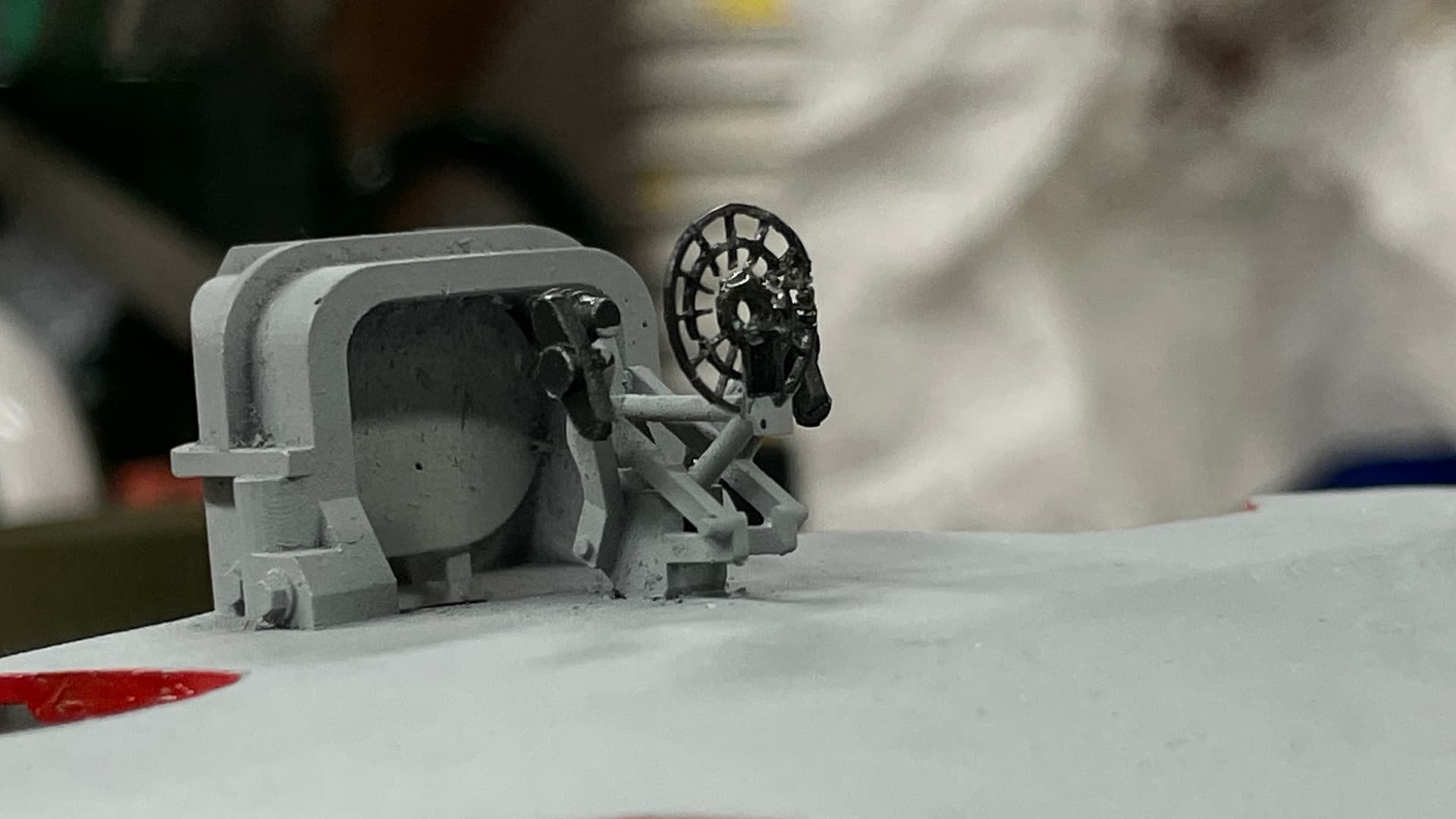
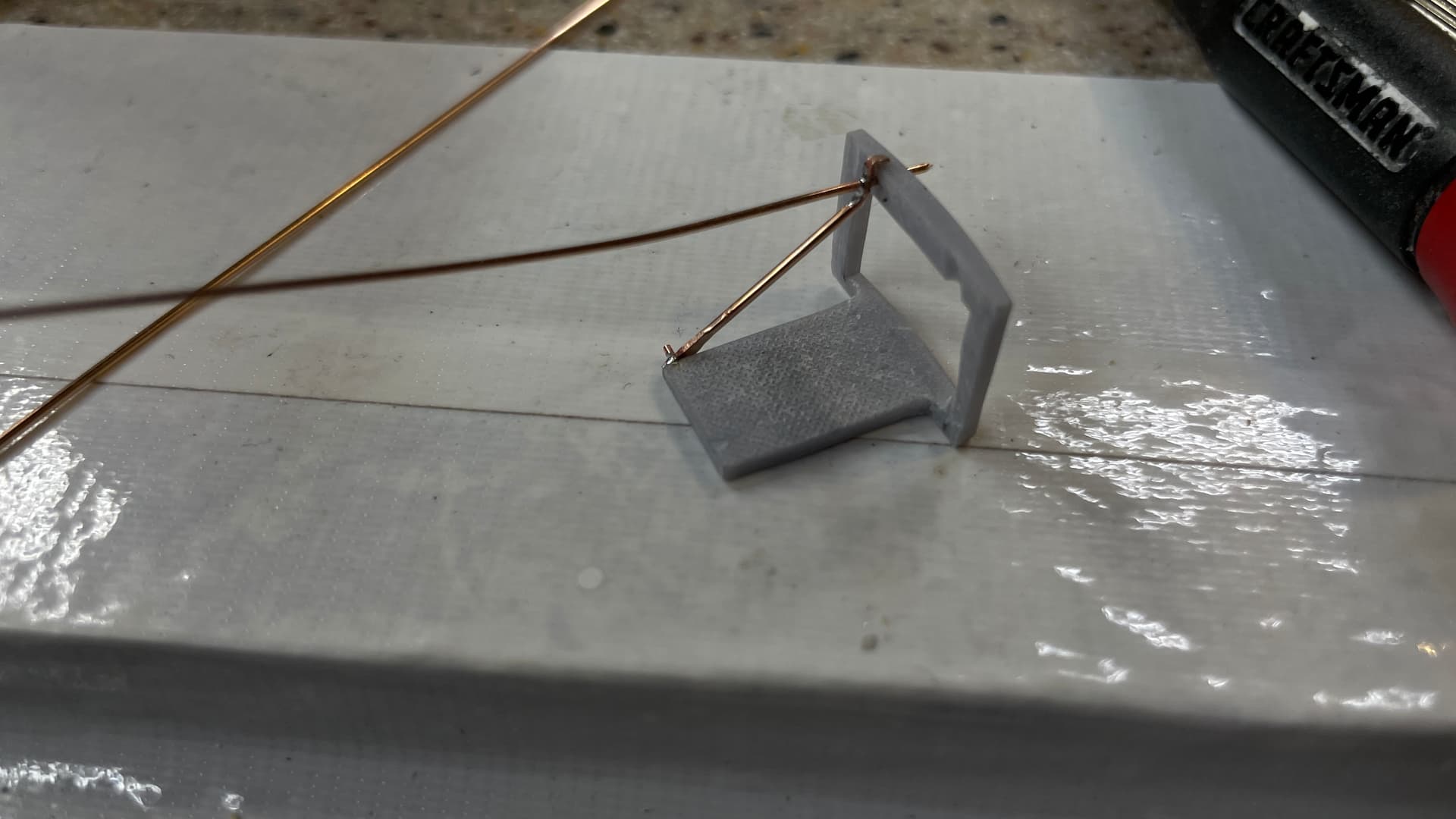
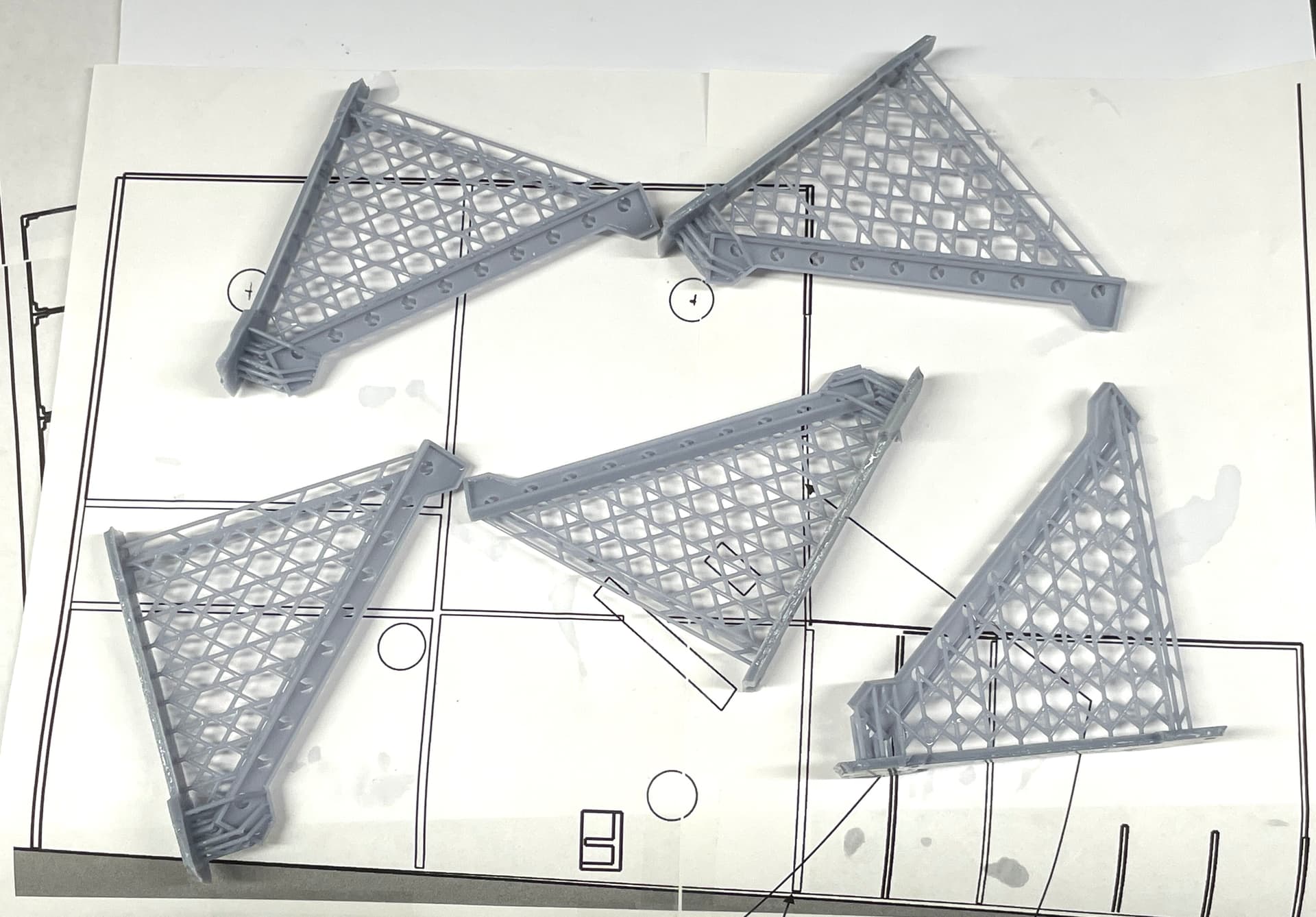
I’m going to try and make cable railings like the real ship has. In 1:48 scale, theoretically, I should be able to. So I designed and printed the stanchions. I think they’ll be strong enough. They should really be brass, but that’s whole other deal and I’d probably go with solid rails not wire. I also printed very tiny turnbuckles. They printed perfectly, but do not have the structural integrity to handle even applying the wire to it, as seen here.
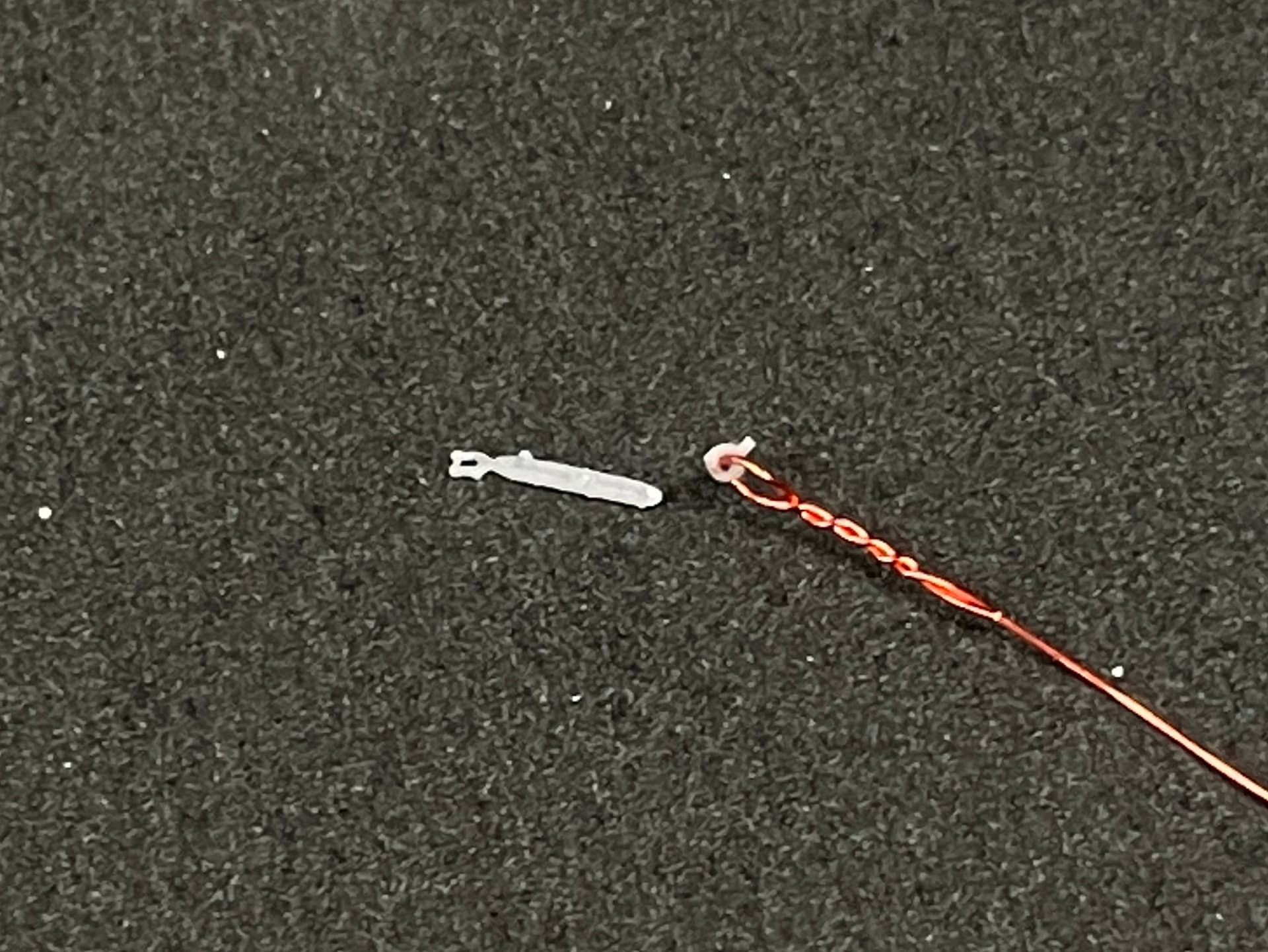
The eye broke off almost instantly.
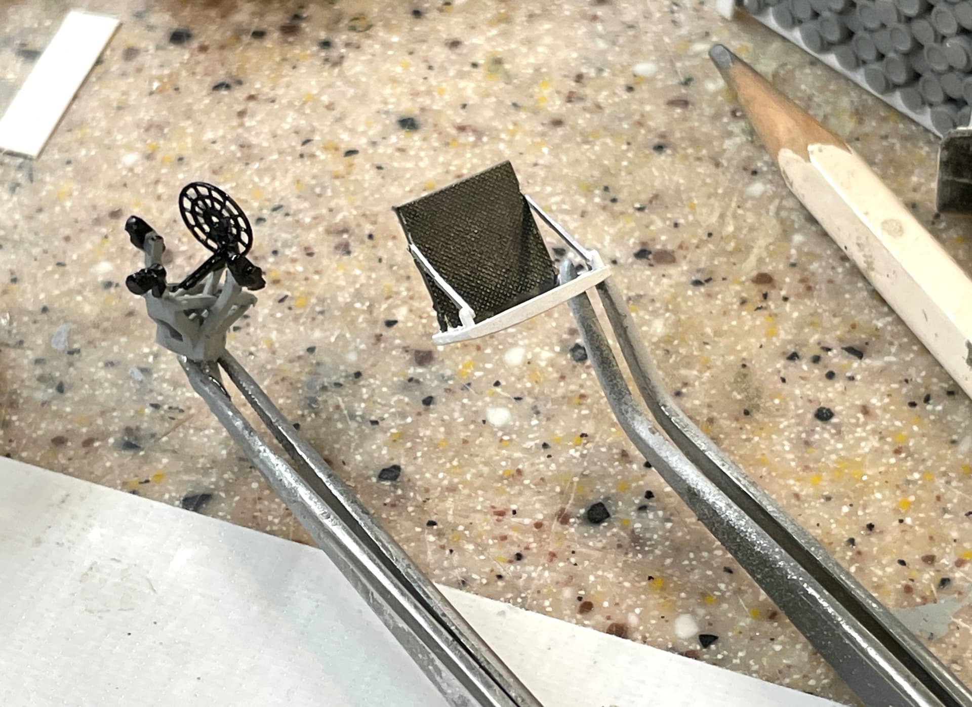
I did thread some magnet wire through the eye on the stanchion and it’s quite strong.
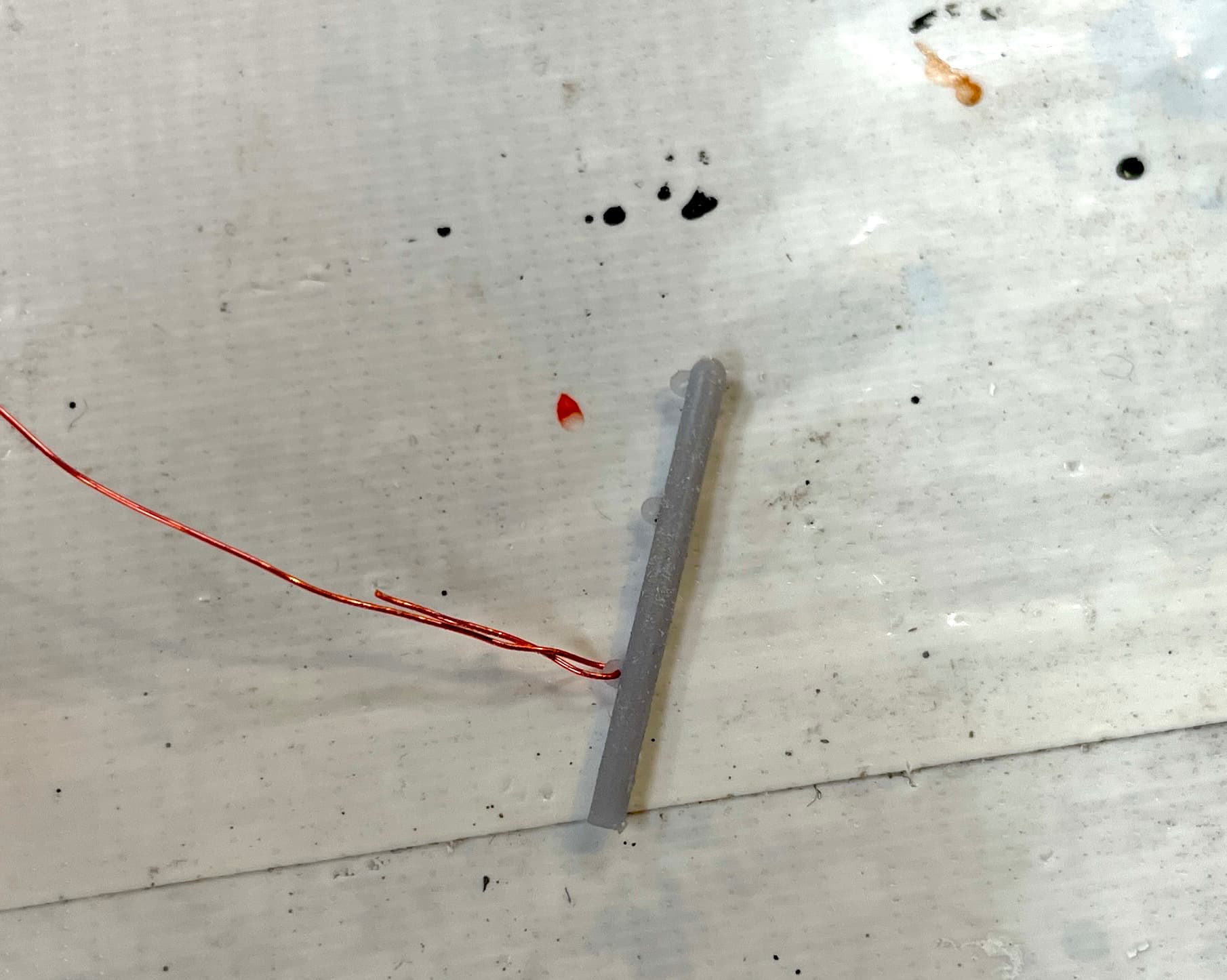
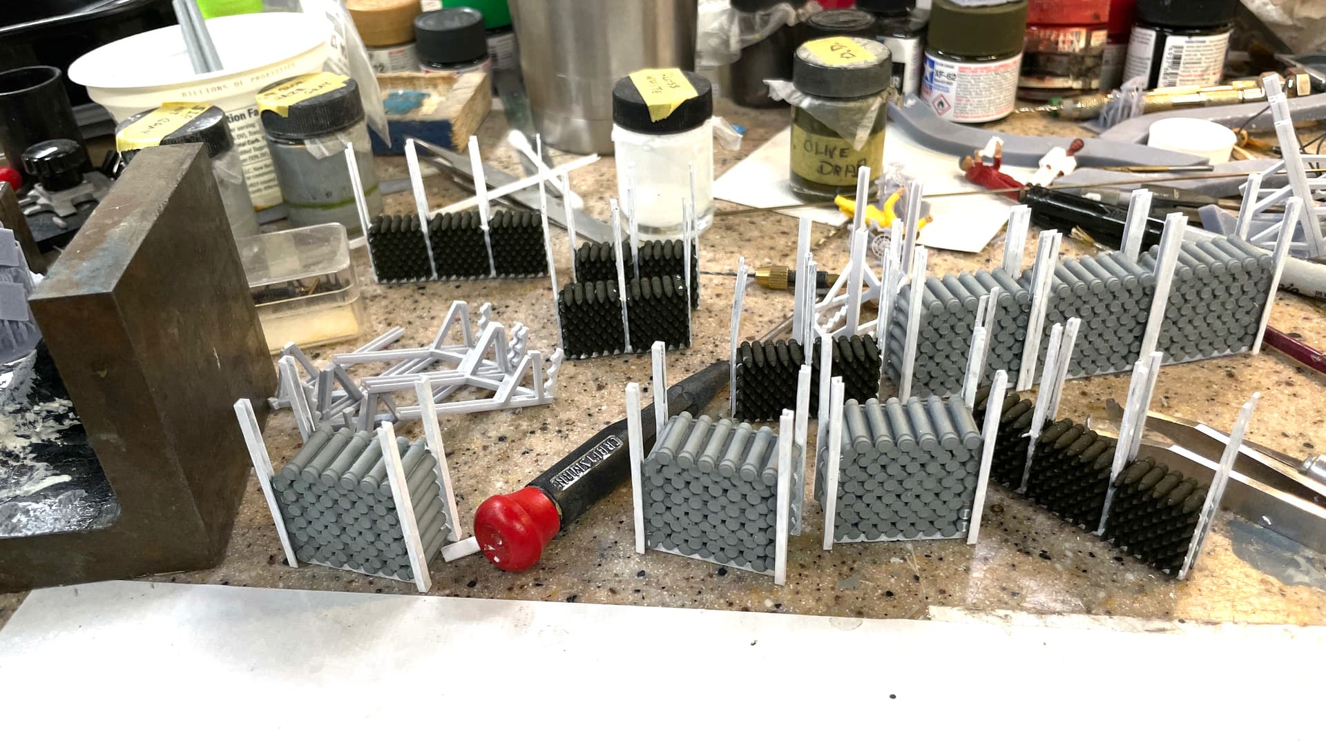
I made two that also have angle braces to withstand the tension of the wire. In fact, I made a whole lot of them.
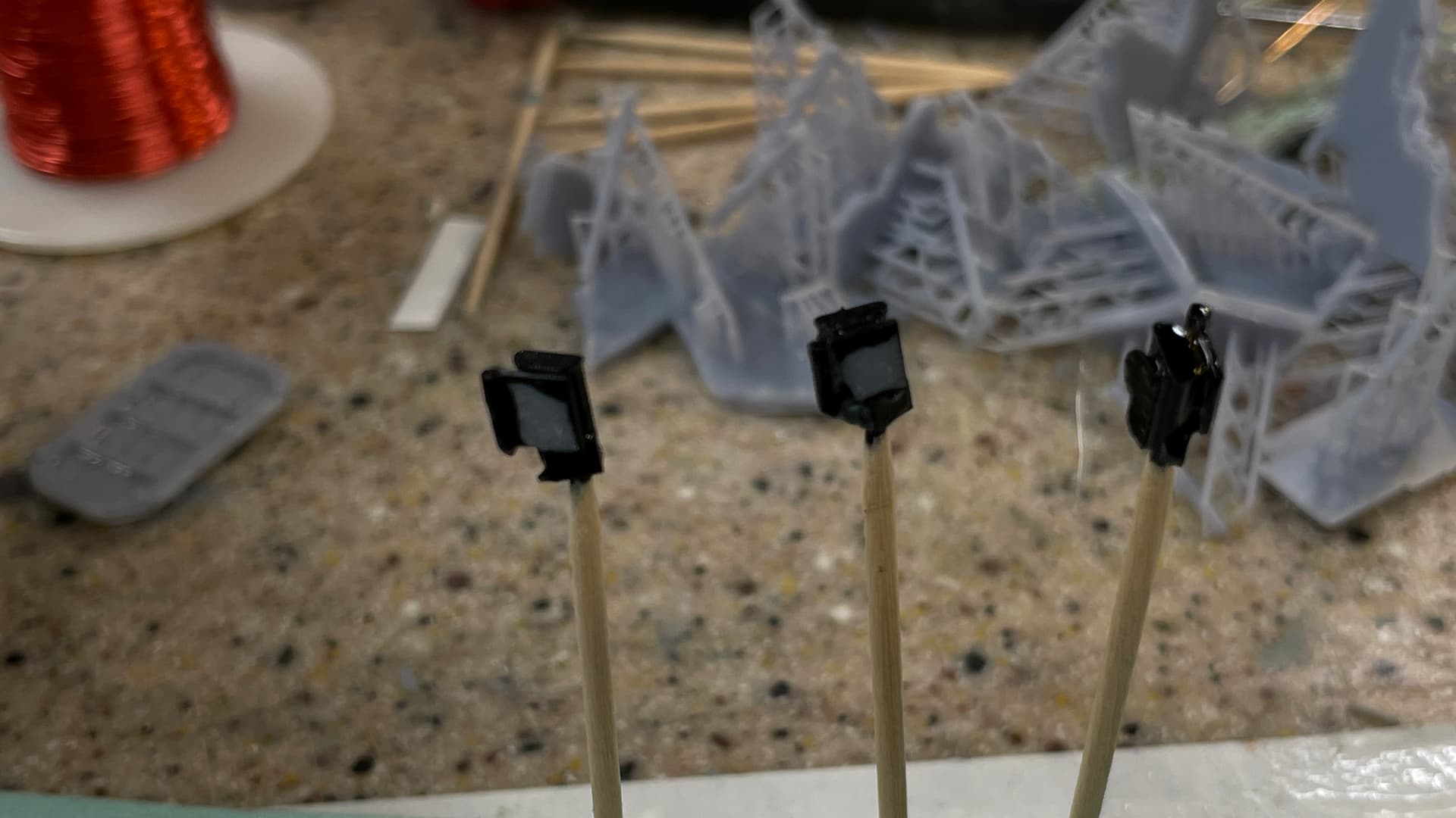
I also printed the telescpe ends for the sighting scopes and painted them semi-gloss black. I purposely did not paint the lens face. I’m going to apply All Clad silver to it overcoated with transparent green to simulate a coated optical surface. I drilled them so I could hold them with a toothpick during the painting process.
Then I went back to cutting wall pieces. I’m using some 3/32 aircraft ply for the main deck. I’m going to plank it and wood glues to wood better than to styrene. There will be a little lip glue to the front edge so you won’t be able to tell it’s wood. Started cutting out the openings for the access hatches.
7 Likes
I was lucky enough to see this in person last week. its truly impressive!
The BattleScale Collectica Show
Seeing it in person is something you don’t forget. I’ve been at the ship five times. May 19 will be #6 and the most impressive I am assuming.
Not much time in the shop since I was spending hours fixing up all the nonesense with my software. Besides the SU extensions challenge (all fixed now), I ran into a problem with CorelDraw and Mac Sonoma. While I could print directly out of CD with tiled pages so I could print full-size plans even thought my printer could only hand letter-sized paper. Mac changed Sonoma so CD no longer prints at all, let alone tiled prints. I would have to buy CD 2024 to have a fix, but I don’t want to incur that cost if only to get it to occasionally print over-large images.
So I did some more research and found a web app that takes over-large PNG files and coverts them to multi-page PDF files that can be printed out of Adobe Acrobat Reader. Adobe also can print “poster” objects, except…. that feature is grayed out unless you subsribe to the Pro edition. Seems lilke I was getting caught at every turn.
The app is PosteRazor. You upload the PNG, define how you want it tiled and it downloads the formatted PDF. No charge!
Like I said, I produce oversized plans a couple of times a year. I don’t want to have to spend hundreds of dollars to just do that. I’m a hobbyist, not business and I’m on a fixed income and, while I don’t mind paying for the software, I don’t like getting hit becasue it no longer does a basic funtion like printing.
So I was able to create full-size, Scotch-taped-together, prints of the decks and elevations I’m going to need to finish the superstructure and lower deck compartments. I bought more styrene sheet to finish the job, I also came up with another way to do a scale railing.
Instead of trying to coax magnet wire to behave better, I’m going to use E-Z Line Lycra thread to make the “Cable” hand rails. I also re-printed the stanchions so the turnbuckles are not integral with the end posts. All the stress will be direct pulling and they will do just fine.
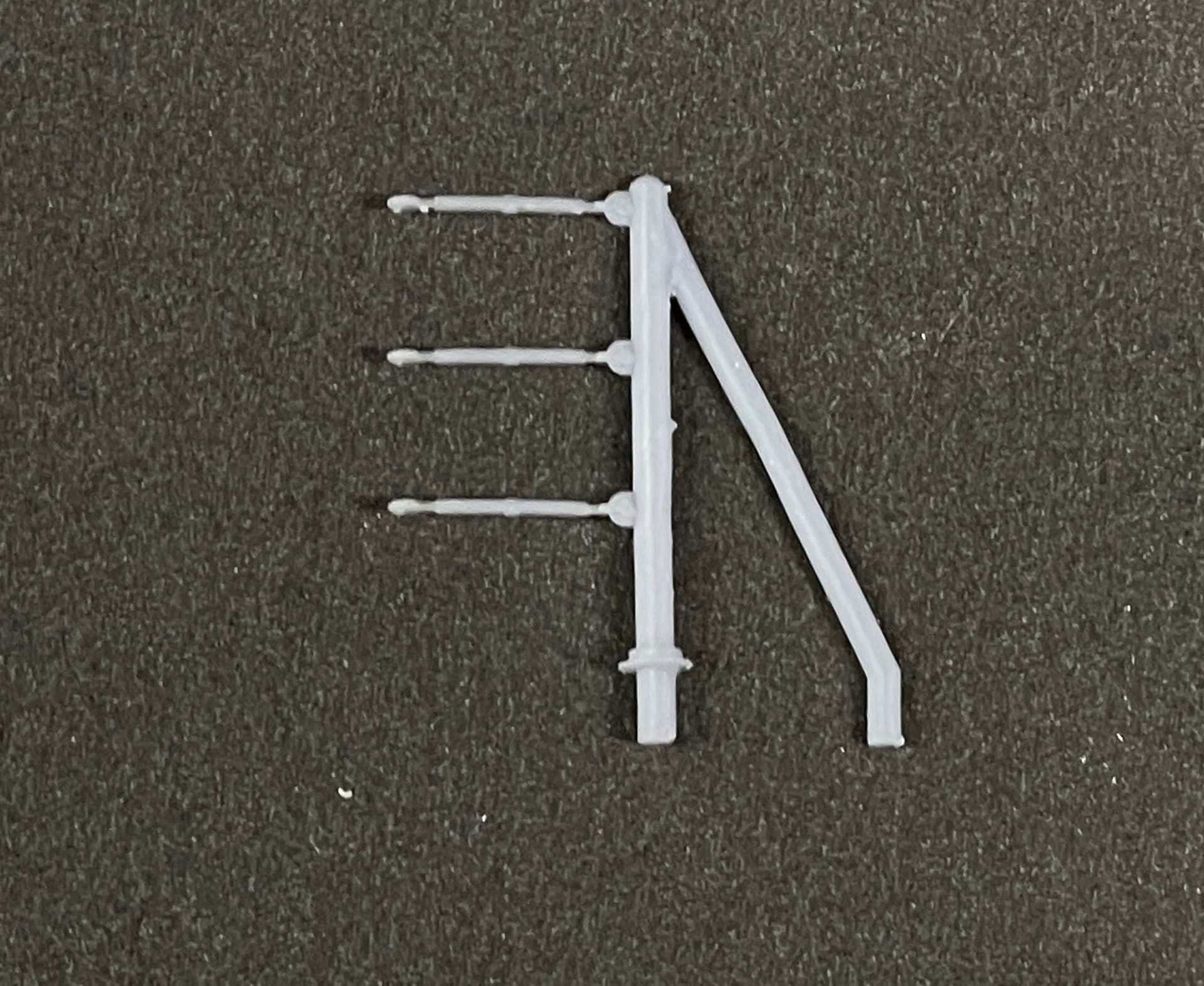
I added a flange at the bottom to control how deep they sit into the decking. I also changed the angle on the brace, so it too would sit nicely.
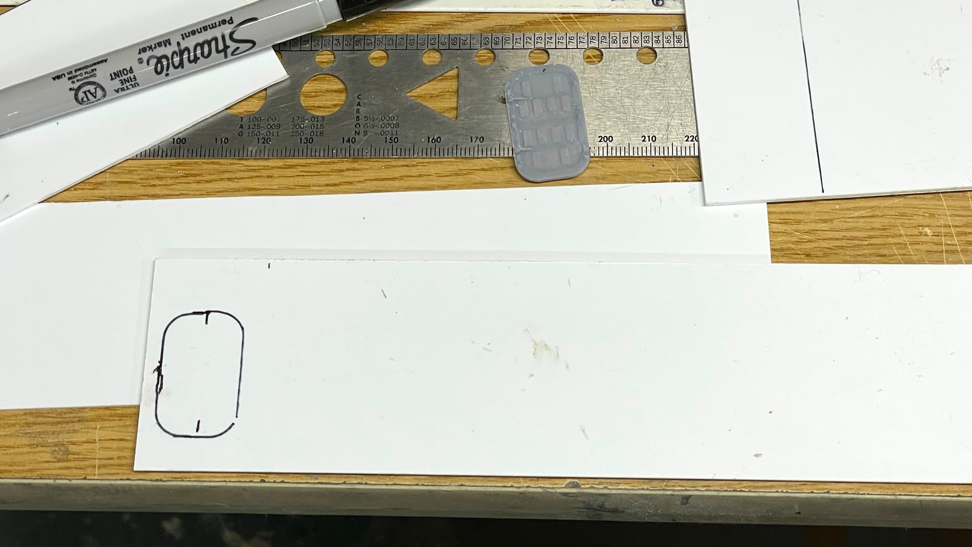
I reprinted the magazine access doors to enlarge the bosses for the locking dogs. They were really tiny and not giving good enough purchase to the phos-bronze handles.
With all the plans done, and enough stock on hand, all that’s left is to turn all of them into walls.
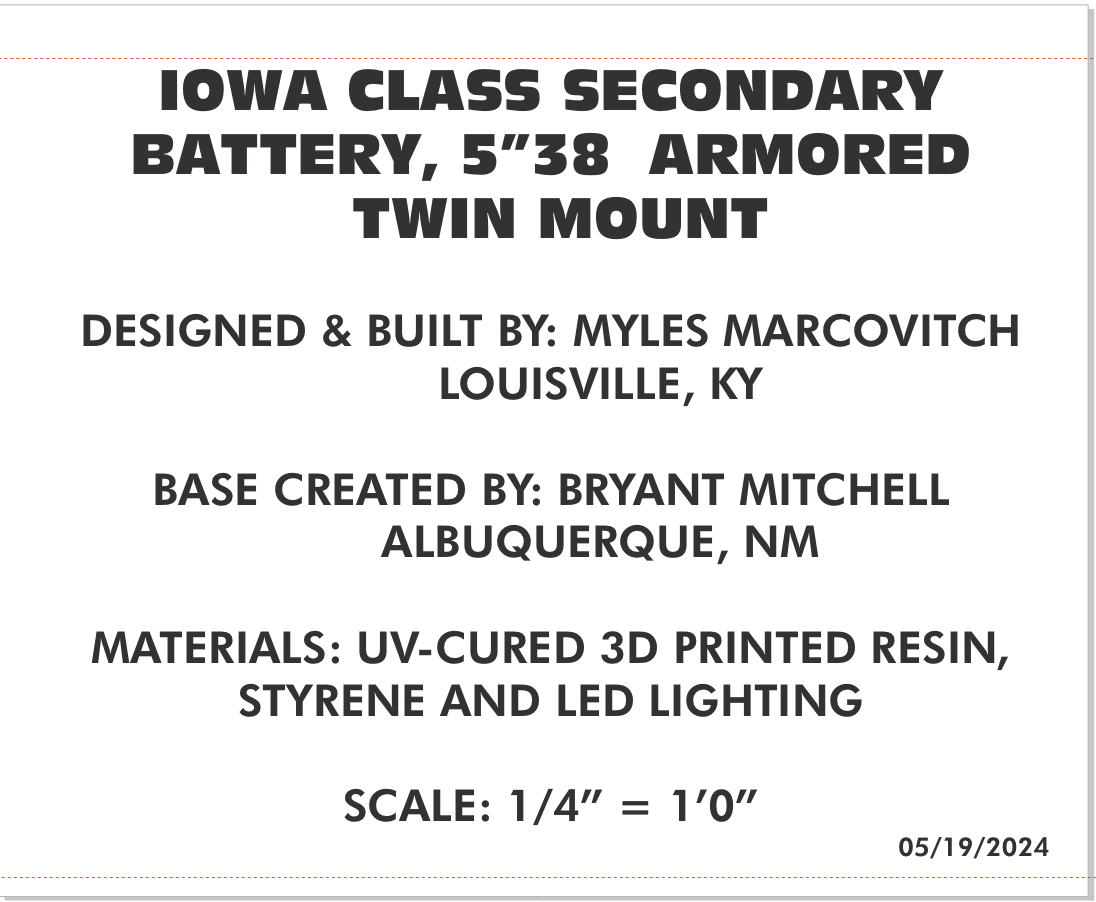
I got the final base size from my friend and drew the correctly size plexiglass case. i will order those pieces this week. I also created the nameplate that will go onto the base.
I created a QR code label to direct folks to one of the build threads I’m doing, so if they so desire, can see all the gory details of creating such a thing.
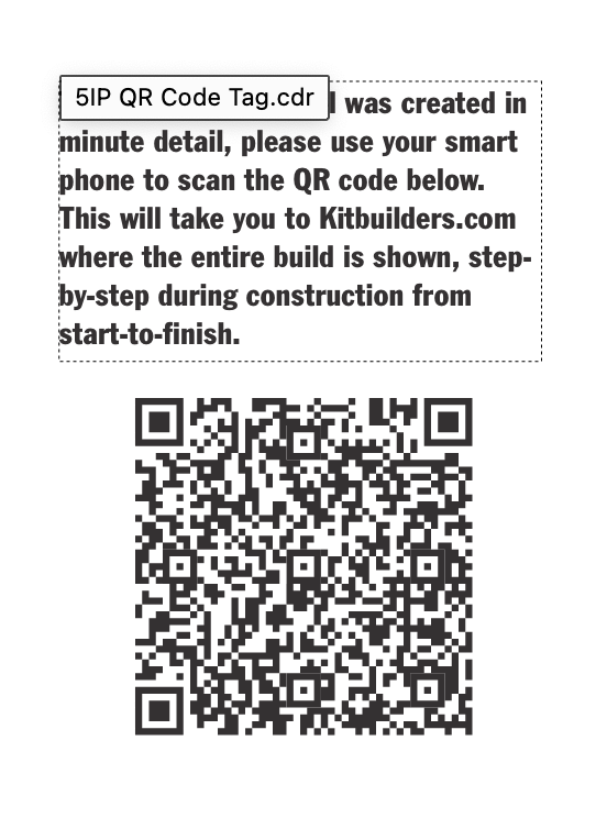
And I have to do the AV program. If I don’t get it done by the delivery date of May 19, it’s something that I can sent later through regular shipping channels. The model can’t. I have to hand-deliver that.
6 Likes
QR code is a smart idea. That will open a few peoples eyes !!
1 Like
Thanks! I did the same thing on the big gun turret. I have no idea how many people checked it out. I need to get feedback from Ryan about any comments about that model. The fact that he’s gung ho for another tells me nobody complained, at least.
Tom, that’s a good idea. I only need large plans a couple of times a year, and if I can get good accuracy by taping together the sheets, I’m okay with that. That said, Louisville is a big enough town that there are services to do what you suggested and I will keep it in mind going forward.
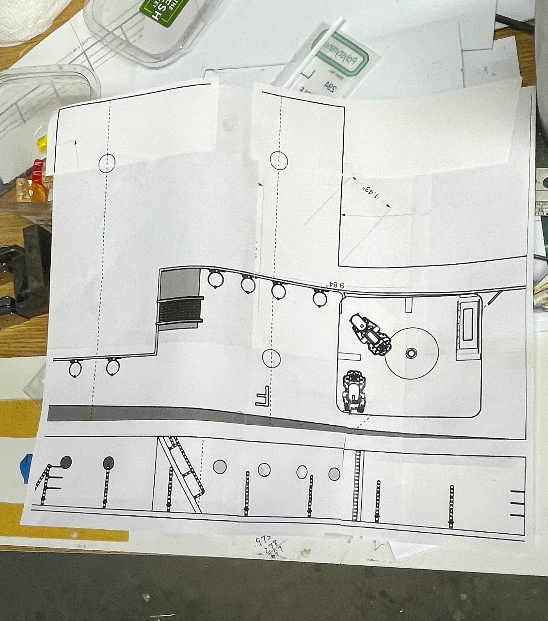
Again, a short session. Between taking walks with my steadily improving wife (up to two miles now), and a haircut, got less than an hour in the shop, but I did do something. Finished putting all the multiple sheets together and now have a full set of plans for each deck. The reaons these are so important is the openings for the hoist trunks.
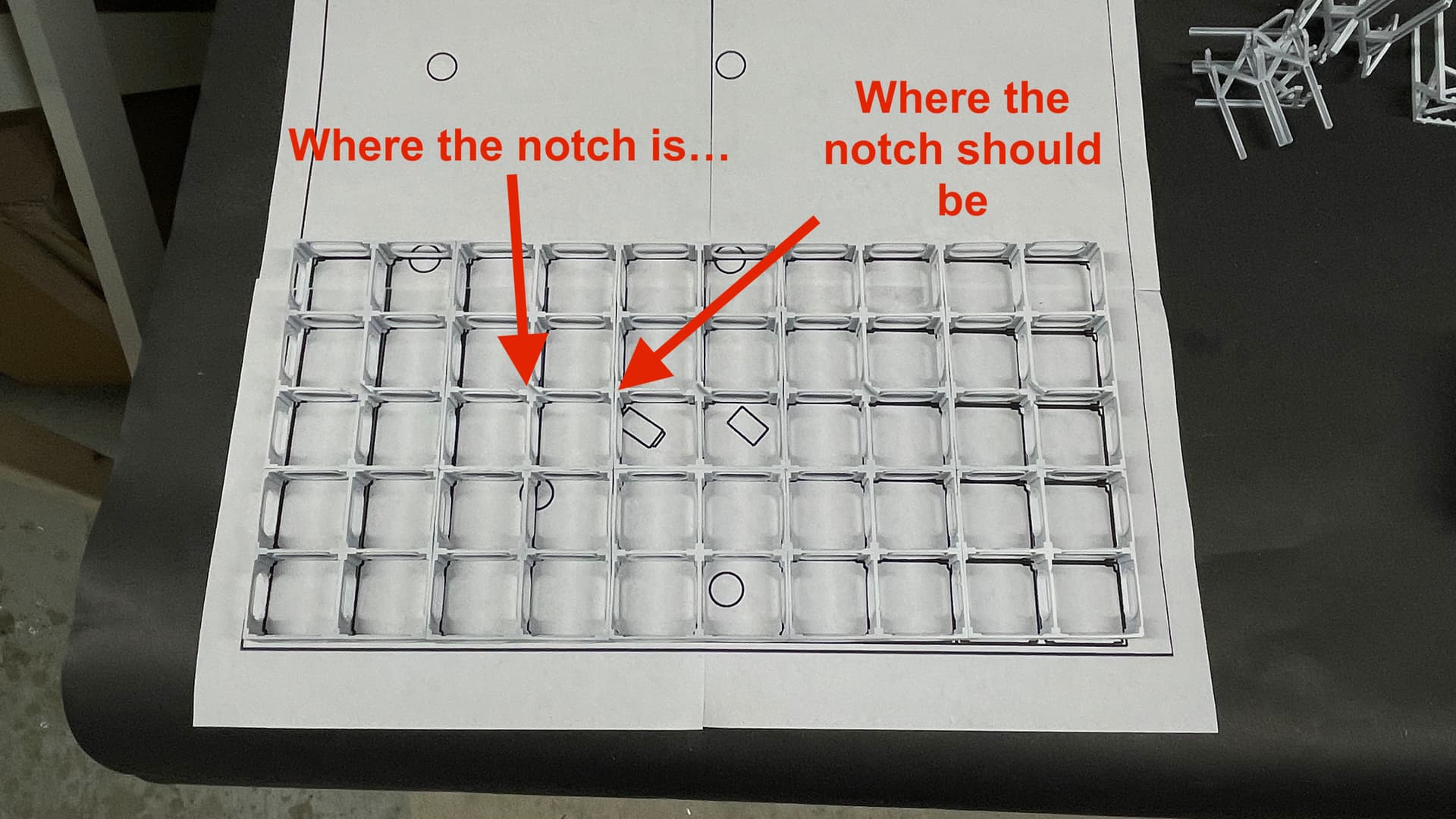
And I found that my relief cuts that I drew into the splinter deck are not aligned with the trunk. It was the way I decided to create the modules. I will have to cut them by hand anyway. The plans are very close to the actual size of the objects.
I cut the door openings old school using the Dremel with a carbide router. I had tried to use a brad-point drill bit to cut the corners, but it tore out on exit and destroyed the piece. I also got very nice prints of the slightly modified Magazine Access Doors. These have bigger dog bosses so I should get a more secure attachment for the wire handles.
Here’s another example of plans all taped together. I have circles drawn for alignment tubes that will keep all three decks in registration, again for those trunks. It must have been fun building the real ship figuring out their pathway through decks and bulkheads as they wend their way from magazine to upper handling room.
I hope to have a longer session tomorrow. I did order the nameplate and have final measures for the plexiglass. I know from experience that it takes on day to do the electrics, one to do the outer case, and another day to plank the deck, and I have probably 10 or more hours to finish the model. I should be done by May 18.
7 Likes
Construction has begun on the Magazine proper. I should say, construction, then de-construction, then construction again, and another de-construction and so on. Yesterday I go the Mag’'s walls done with all of their cutaways. One set was supposed to be three walls with identical cutaways. I first tried to use a jewelers saw to cut them laminated together. This wasn’t working. I then resorted to using the Dremel with carbide routing bit. This was a multi-step process: Routing, small drum sandings, hand sanding, and some more power sanding.
I reprinted the doors and added all those little handles. That took almost an hour.
That brings us to today. I was anxious to get started gluing walls together. Maybe a bit too anxious. I didn’t make one mistak, or two. I made three. It’s my ADHD kicking in.
All the walls had angle stock glued to give more strength. It sure did! When I needed to take things apart (with more to come… unfortunately), they were very difficult to take apart. I have a steel plate with special magnets for building model structures purchased from MicroMark years ago. This is a good use for it. I got the first wall glued in nicely.
I then glued in the second wall. Only much, much later I found that I glued it in reversed. Remember those three walls with the same cutaway, well… the outermost wall opening should be on the left (looking at the wall). The result is the cutawys don’t align as I wanted them to do. And there’s a little partitiion wall which you now see its exposed edge. My first dumb mistake by not paying attention to my own planning. It’s not a critical error because I kind of like that you see on both sides of that little wall which shows the door to enter the magazine.
I then glued it all up and found my second screw up. I put the rear wall in upisde down. I noticed this when I took a picture and saw the door sill was now very high. It’s supposed to be 16 scale inches, and it was more like two feet. I ripped it out and re-glue it correctly.
I got all the walls in and then found two more errors. The first doesn’t matter much at all. For the left blank wall I used a piece that was almost exactly the same size, but cut from the wrong thicikness stock. It’s also not as perfectly fit at the “real” one. I’m not doing anything about it. The next one is more seriious.
In this image you can see the rear door sitting much to high on the wall.
The fourth screw up is I forgot to cut the openings in the front of the powder room to include the spaces for the scuttle doors. These are an esesntial part of the magazine and I printed them. I’ve thought about how to modify the wall without ripping it out, but am coming up short. I think I have to make a new one and reinstall. DOH!
I want to put in some ceiling beams and cobbled one by hand to see how it will work. I was satisfied with it, but crafting them this was was taking way too long. Besides, they have lightening holes to pass piping and wiring, which was much harder to do in styrene. Answer: Draw and 3D print them.
I don’t know the spacing between them and asked Ryan if he can provide that. Speaking of Ryan. He’s geting his 15 minutes of fame. He was mentioned a lot in a New York Times article this week on the Battleship New Jersey’s makeover. It a big …. Deal.
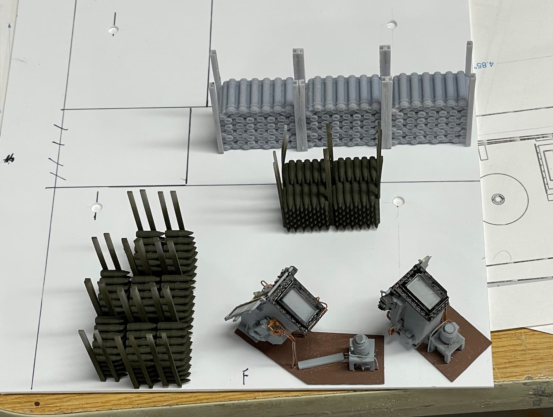
I put some furnishing in the magazine and took some pictures. They look like my drawings. When painted and lit, it will be interesting.
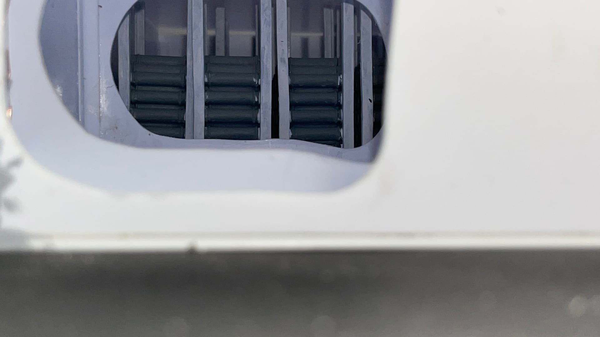
In this next image looking in the front, the large opening into the powder room should have the scuttle doors in it. Now it’s just a big hole.
It should look like this.
Had an “interesting” experience yesterday. I was using the 0.015 carbide drill to make the holes for the dog levers on the reprinted doors. These tiny drills are ground on the ends of 1/8" carbide shafts. I reached into the special box they come in, only to have one impale itself on the second finger of my right hand… DEEP… all the way in. I ranked my hand off and the drill came out of the case with it. Then I shook it and the drill flew onto the floor. Hurt like heck! When I looked at the drill, it was missing the bit part. Was it in my finger? I swept the floor to find since they always break when dropped, but couldn’t find it. Meanwhile, it’s not hurting any more, Tungsten Carbide is effecetively inert and won’t degrade in my finger, so we’ll see what happens. It was very surprising!
6 Likes
Dang. If it’s not hurting, its probably out.
2 Likes
Give it a couple of days… ![]()
![]()
1 Like
Naw… I don’t think there’s 3/8" of tungsten carbide in the finger. It’s not hurting at all.
Another problem solved! Whew!
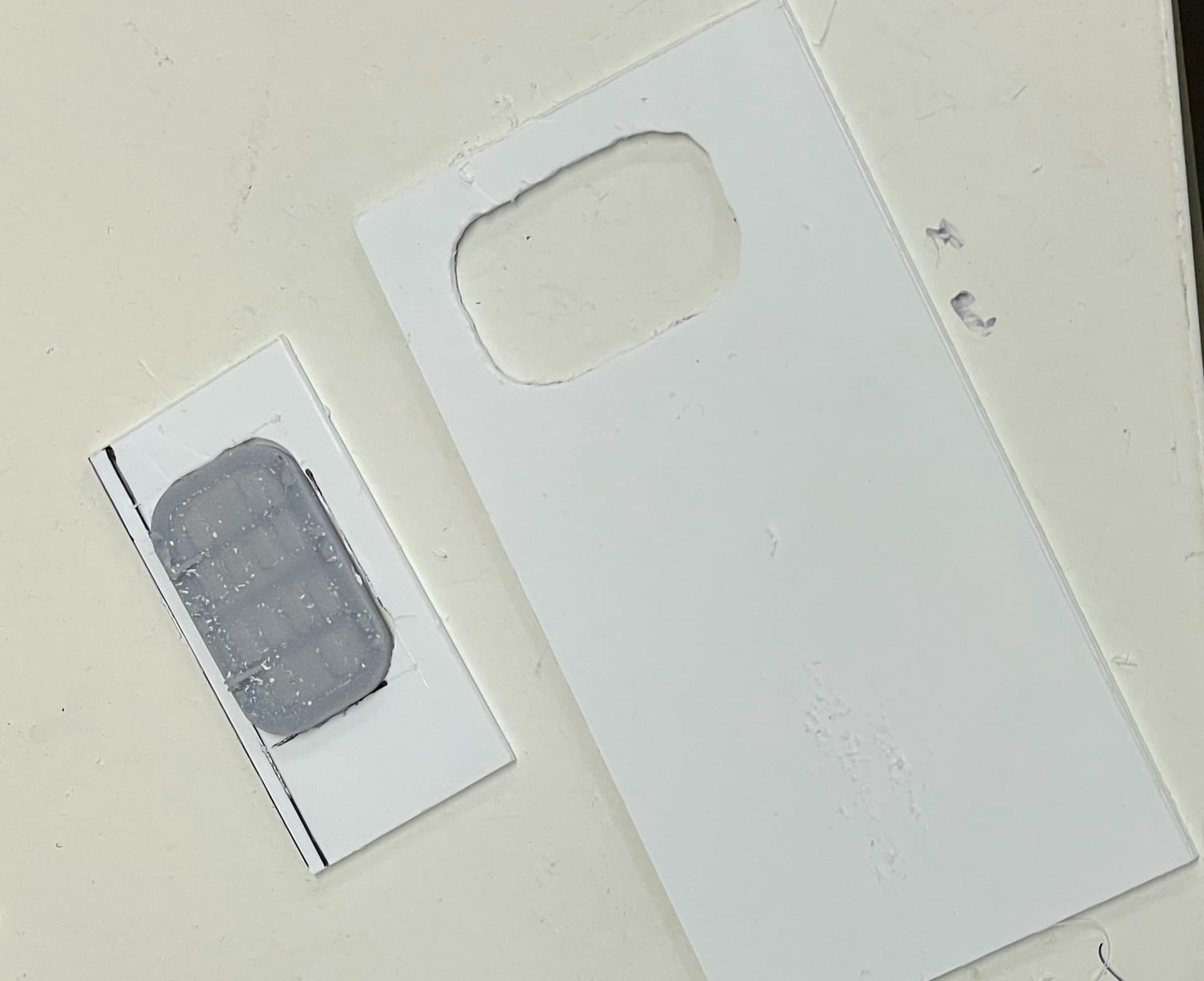
I went to sleep last night working through the various ways to fix that wall without ripping anything out. I came up with laminating an new wall on the front with the proper cutouts for the scuttle doors. Actually, it looks like the powder magazine walls are very thick and may be filled with concrete. Doubling the walls thickness isn’t so far fetched.
To do this I traced the cutaway on the existing wall and matched what I was opening on the repair so they would look okay. I traced the scuttle door and between router and sanding got a very nice, close fit; much better than my previous attempts.
I glued the new all in place with good old Testor’s tube cement since it gives more working time. The cutaway needed some fine touching up and I was able to reach through the front wall’s opening with the Dremel Flexishaft and cleaned it up.
The new opening give less view than before, but those doors had to be there. They are an essential piece to isolate the powder from the rest of the ship.
I printed the first set of long roof girders. Ryan answered me by suggesting the spacing is the same as the ship’s frames = 4 feet. I’m going to enlarge that for a couple of reasons, mostly to ensure that the hoist trunks have a straight shot out of the magazine, and not cast too many shawdows from the ceiling lighting. Prints are essentially perfect. Sure beats cobbling them together by hand.
Asked for a quote for the Plexiglass, my friend’s putting the laquer on the base, and the nameplate is ordered. If I get the plexiglass by end next week, I will finish that on time. Takes one work session to build the case.
I’m also making a good start on the AV program.
8 Likes