Work progresses…
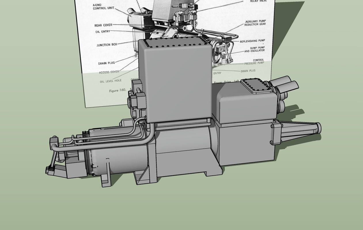
I designed the Training Gear hydraulic plant. This sits down between the girders on the gun house’s right side behind the Trainer’s seat and regulator. Luckily this one is drawn in profile in one of the cross-section images I found so I could get the profiles down. I’ve scaled these drawings so they are representing correct lateral dimensions.
There are two output shafts that extend out of the end and I probably will make these out of correctly sized wire. It was gratified after finishing the drawing that it fit perfectly in the space it was supposed to. I have an add-on that facilitates making those neat curved edges. Also, SU is pretty easy to draw complicated pipe runs once you know what you’re doing with connecting lines and adding curves to them.
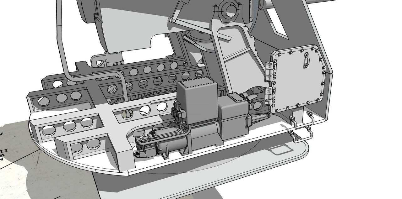
Here it is dropped into position.
Next up will be to design this units hydraulic counterpart, the Elevation Gear Hydraulic Plant.
As in the big gun’s turret, all the systems are driven by hydraulic motors with the pressure generated in a remote motor/pump setup. In the case of the big gun, the motor/pump (A-end) was physically remote from the hydraulic motor (B-end), but in the case of this smaller turret complex, the motor/pump was directly in line with it’s b-end hydraulic motor.
With my newly refined printer setup, I have no doubt that all that delicate piping will render. It should look pretty good.