5"38 Cutaway Turret Complex; CAD and 3D Printed

On Monday the model will be done! Today was a mishmash of tasks to finalize the build. And there was the usual passal of complications that seem to crop up at the last minute. Alls well that ends well" sums up the day.

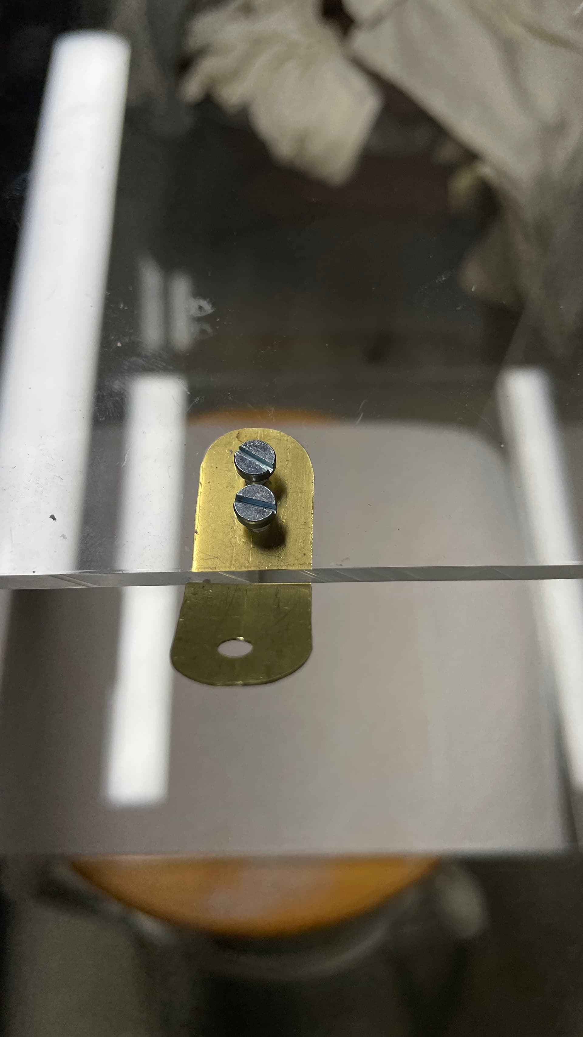
I started by fabricating the brass clips that would secure the case. I was halfway through when I realized that I should glue the GH/UHR assembly since it would need a good hour of setup time before I could handle the model. To do the wiring it had to be in place and be able to let me lay the case on its side to access the bottom.

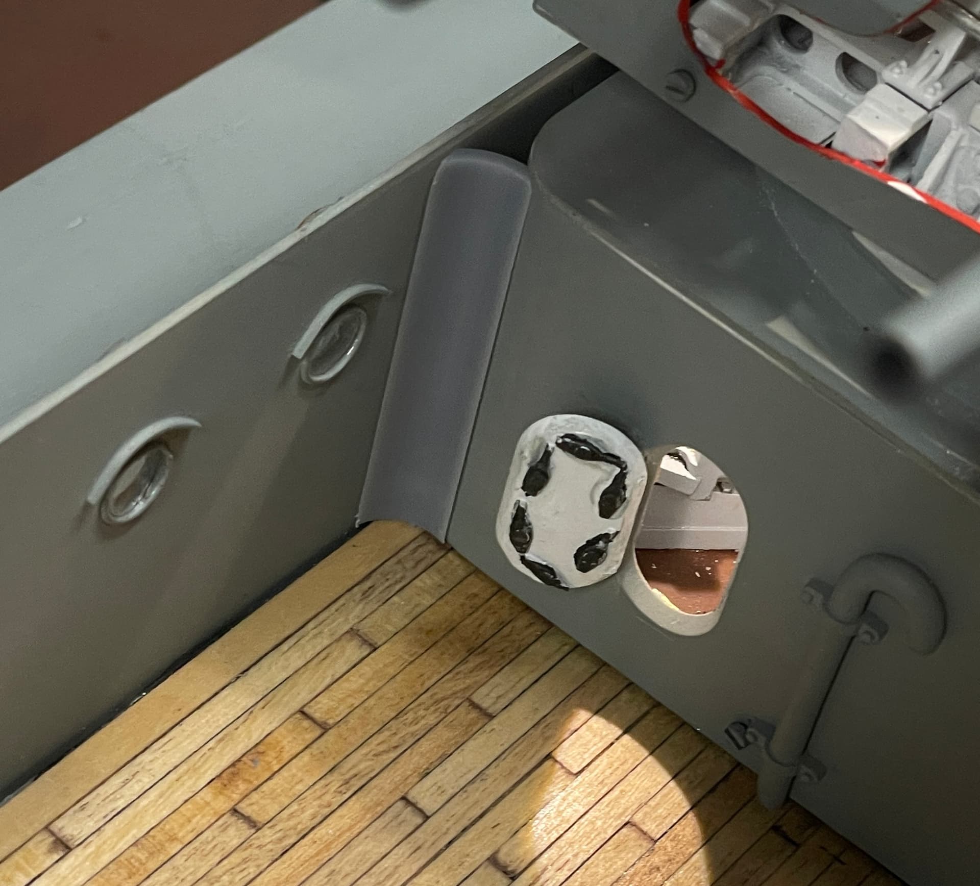
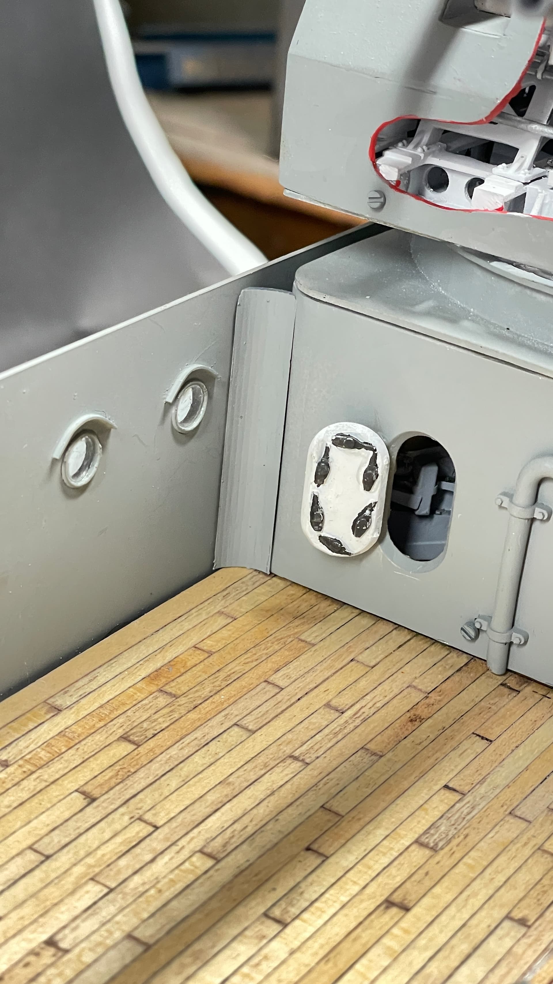
I marked its location on the deck and applied the J-B Structural Cement so it did not ooze out of the edges.

The assembly sits just a bit proud of the superstructure bulkhead due to the screw heads protruding. Believe it or not, this little bit almost caused a problem.

While drying I got back to making the locks.

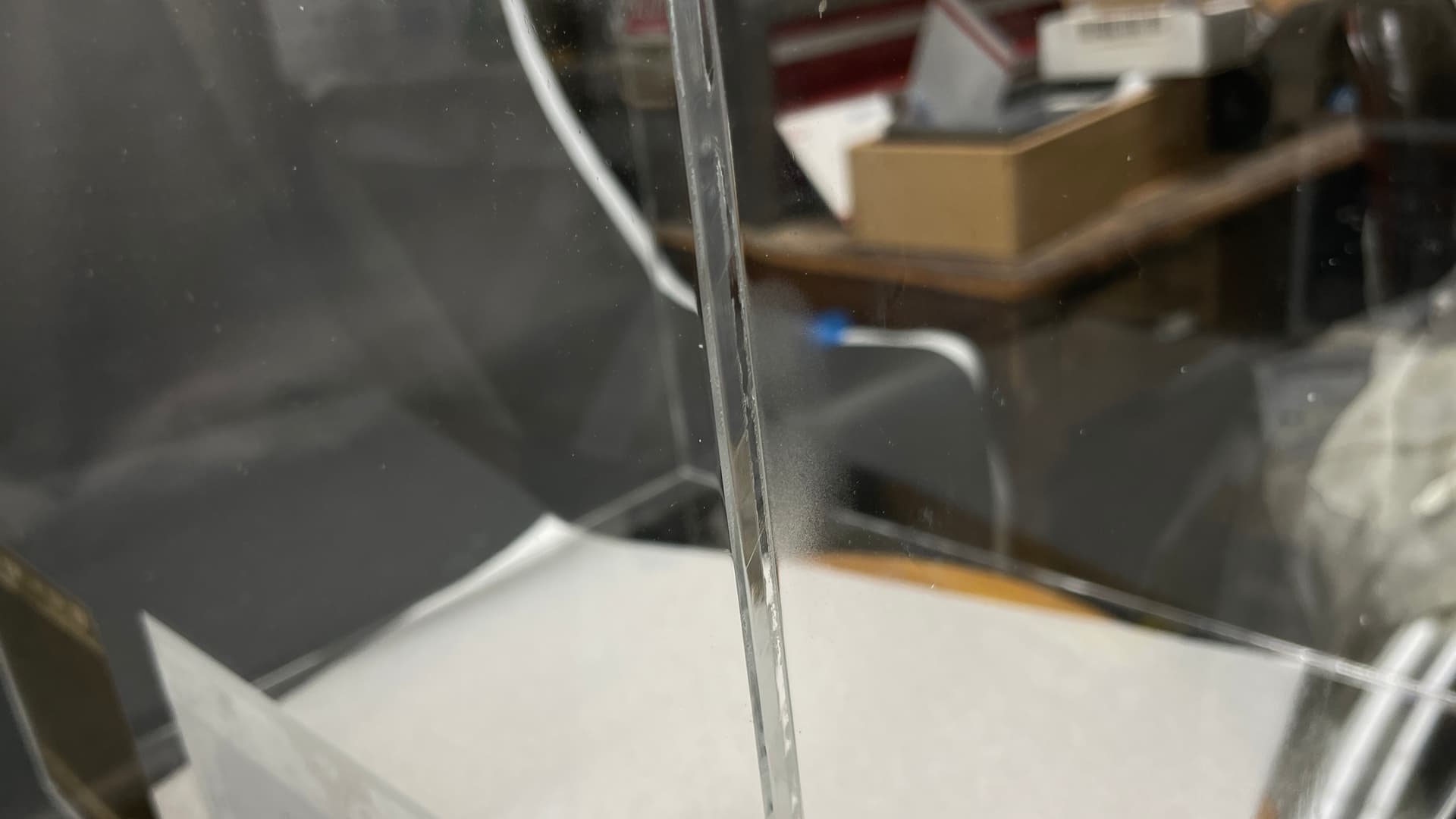
Before drilling I did a bit more flame polishing. In the lighting where I was doing this showed that it wasn’t done enough. I also overdid it in one spot. Yes… you can overdo flame polishing.

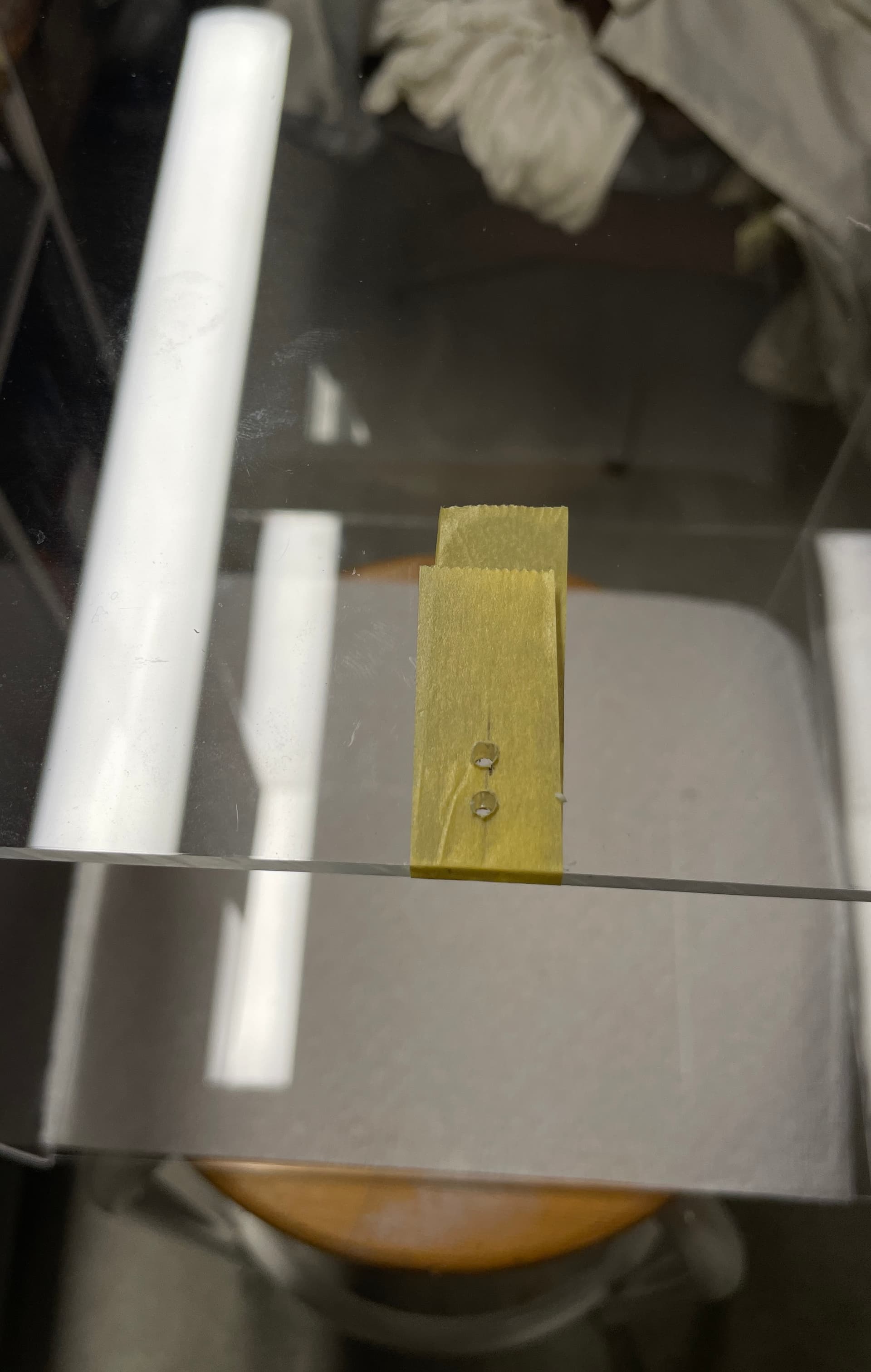
Drilling acrylic can be tricky due to fracturing upon exit at the hole’s bottom. To counteract I used masking tape on both sides. It also provided a place to mark the locations.

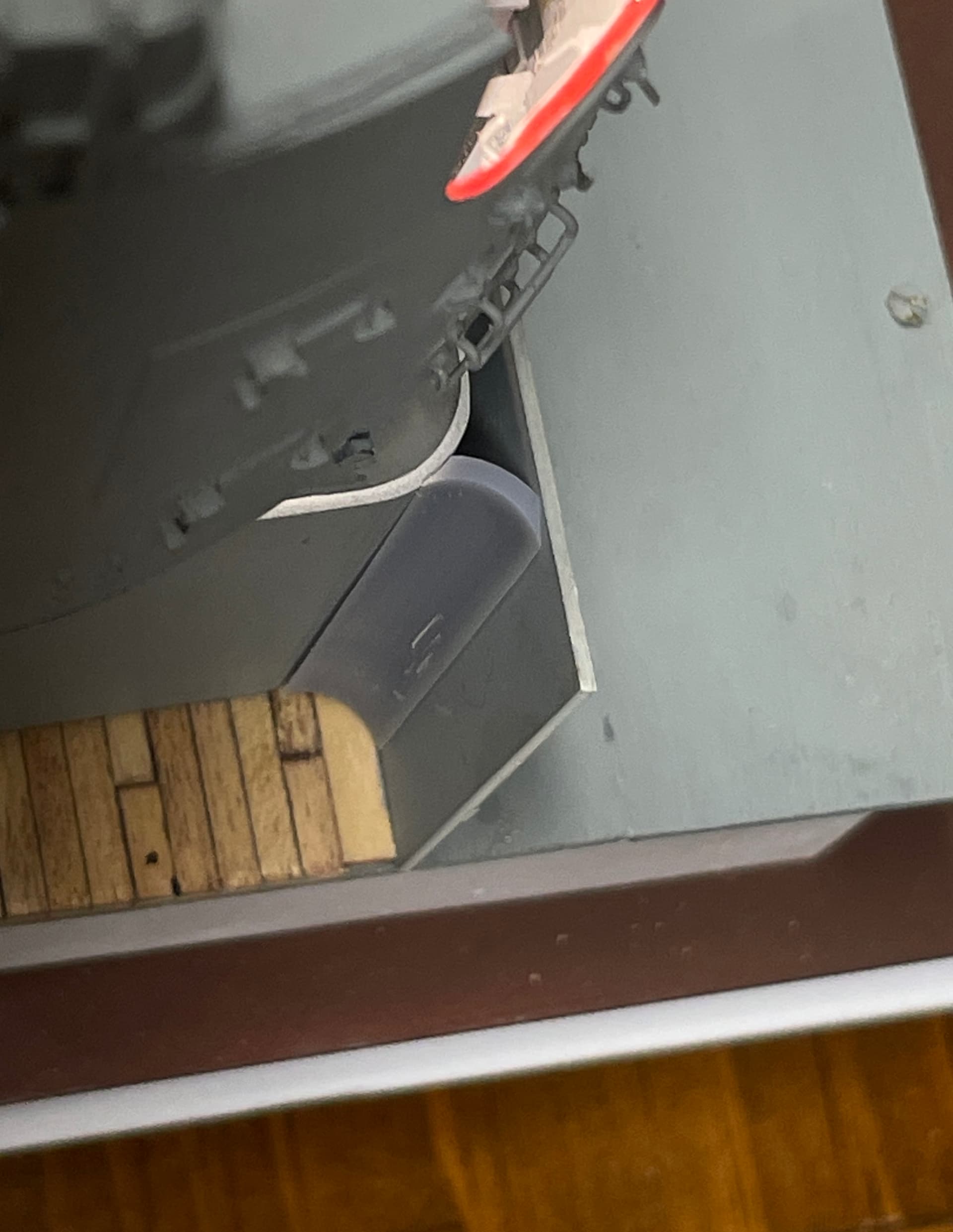
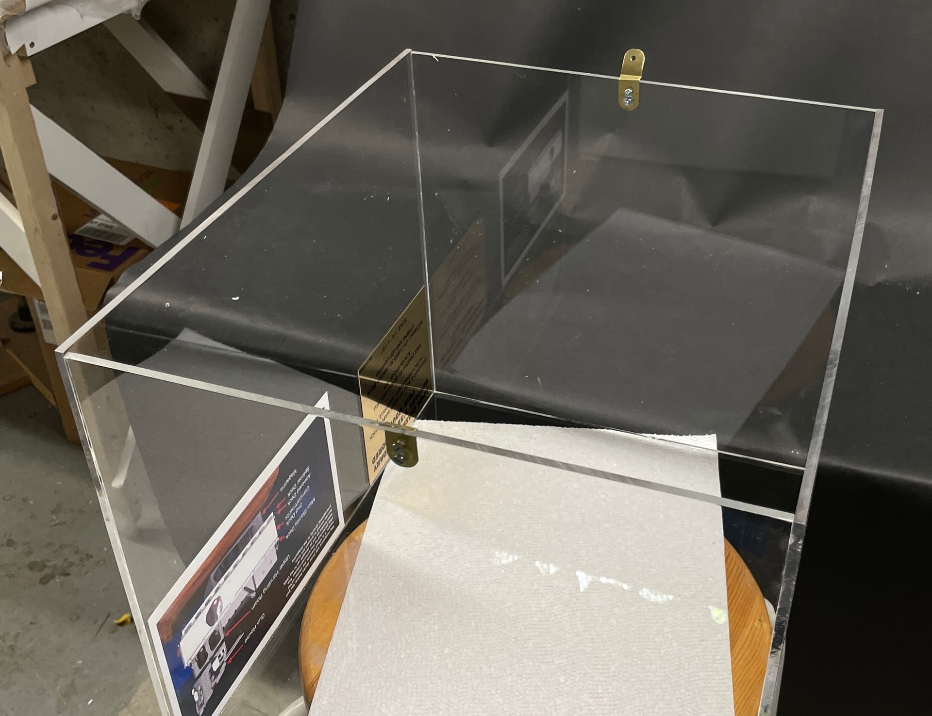
The bracket is screwed in from the back side and passes under the end acrylic sheet. The 1/16" gap came in handy for this and I used it.

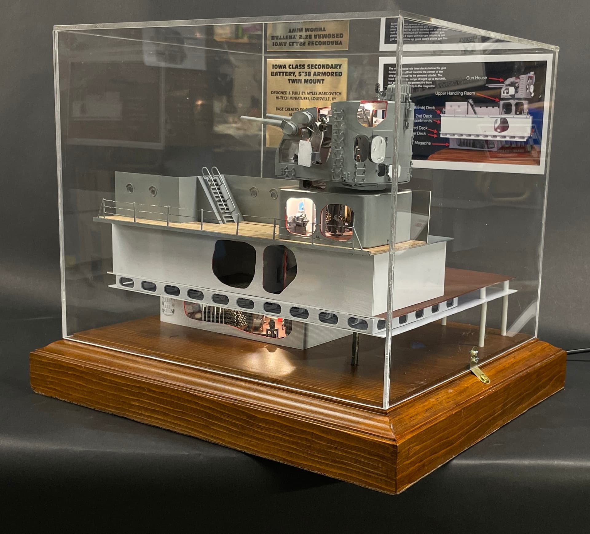
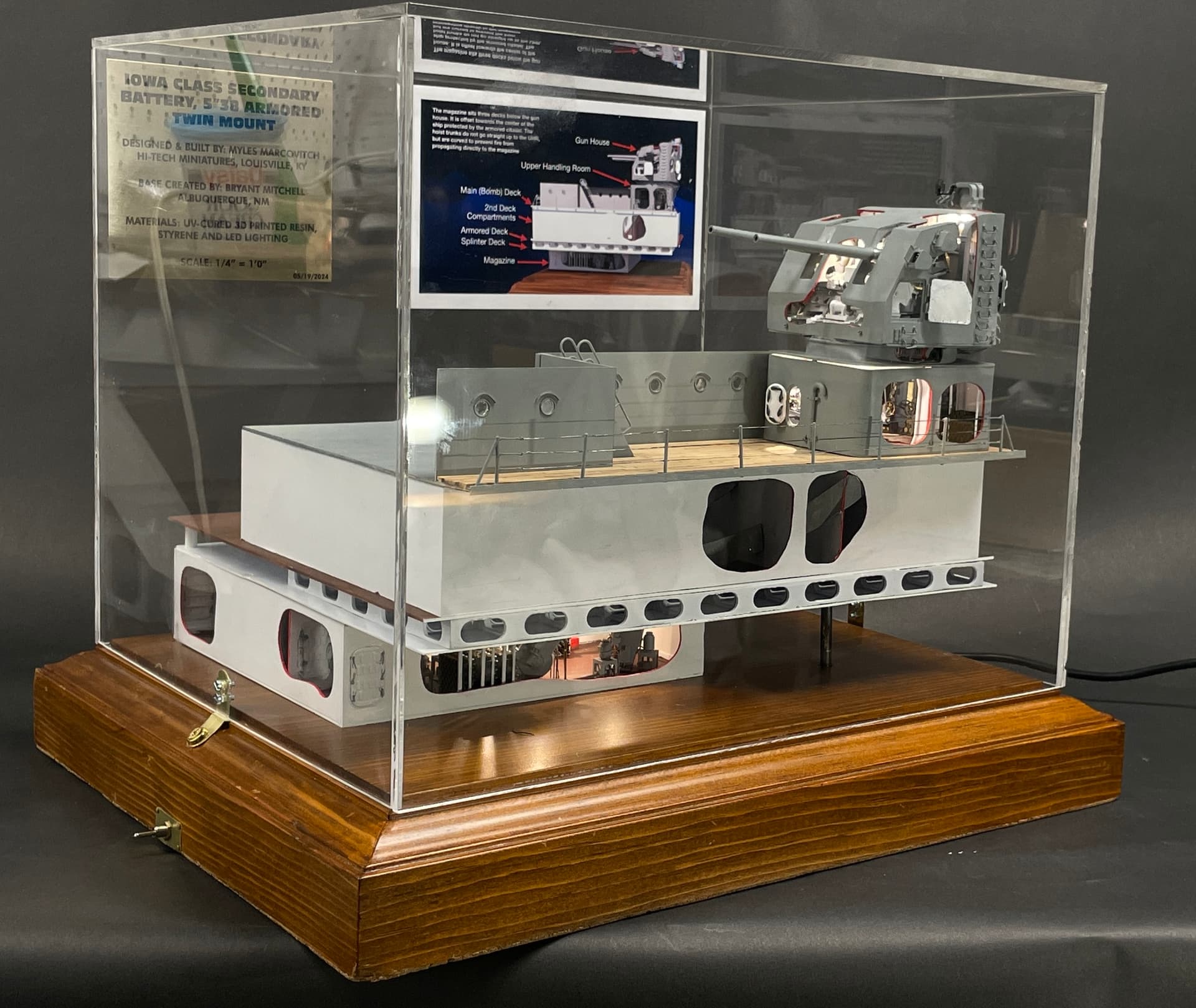
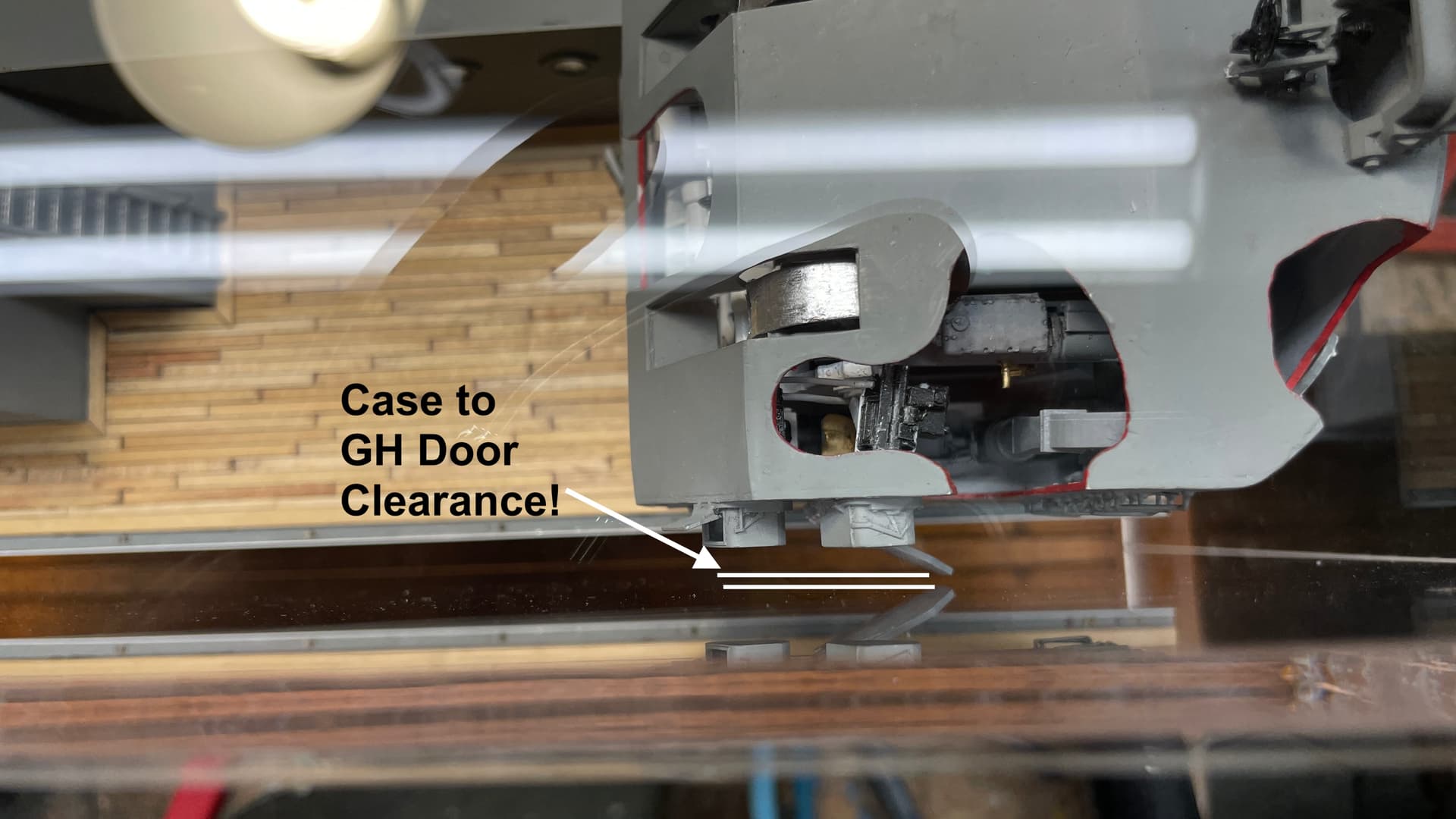
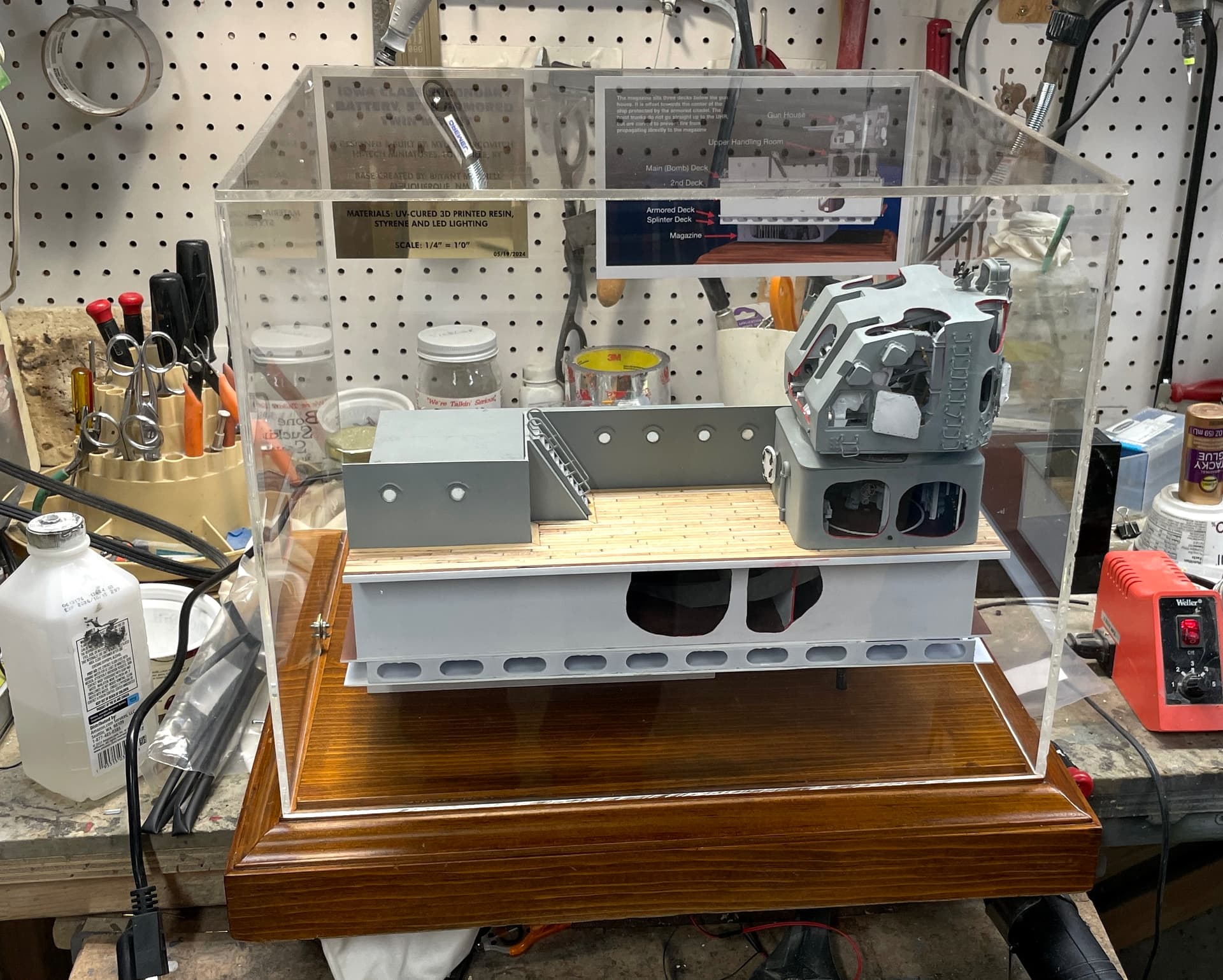
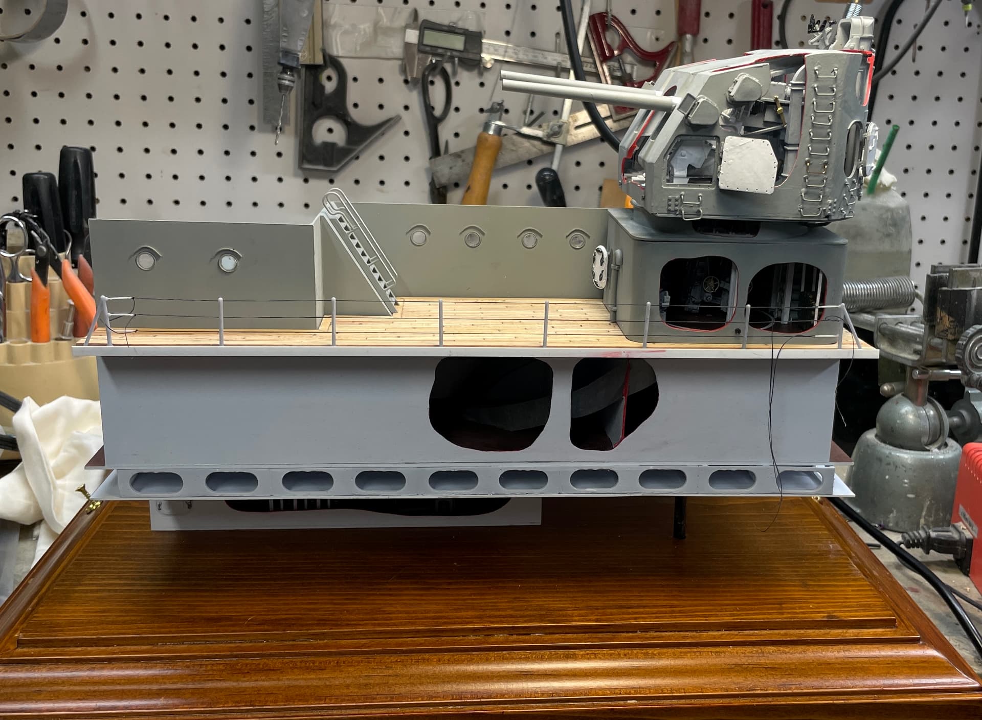
I fit the case over the base with the model in it and found that I only had a fraction of an inch clearance between the open access GH hatches and the plexiglass. Luckily, I built in some play and was able to scooch the case forward a bit to gain just a bit more room. I was very, very lucky. I was concerned about the protrusions on the gun house as I drew it and the base, those open doors were not in the drawing. If it didn’t fit, frankly, I have no idea what I would do.

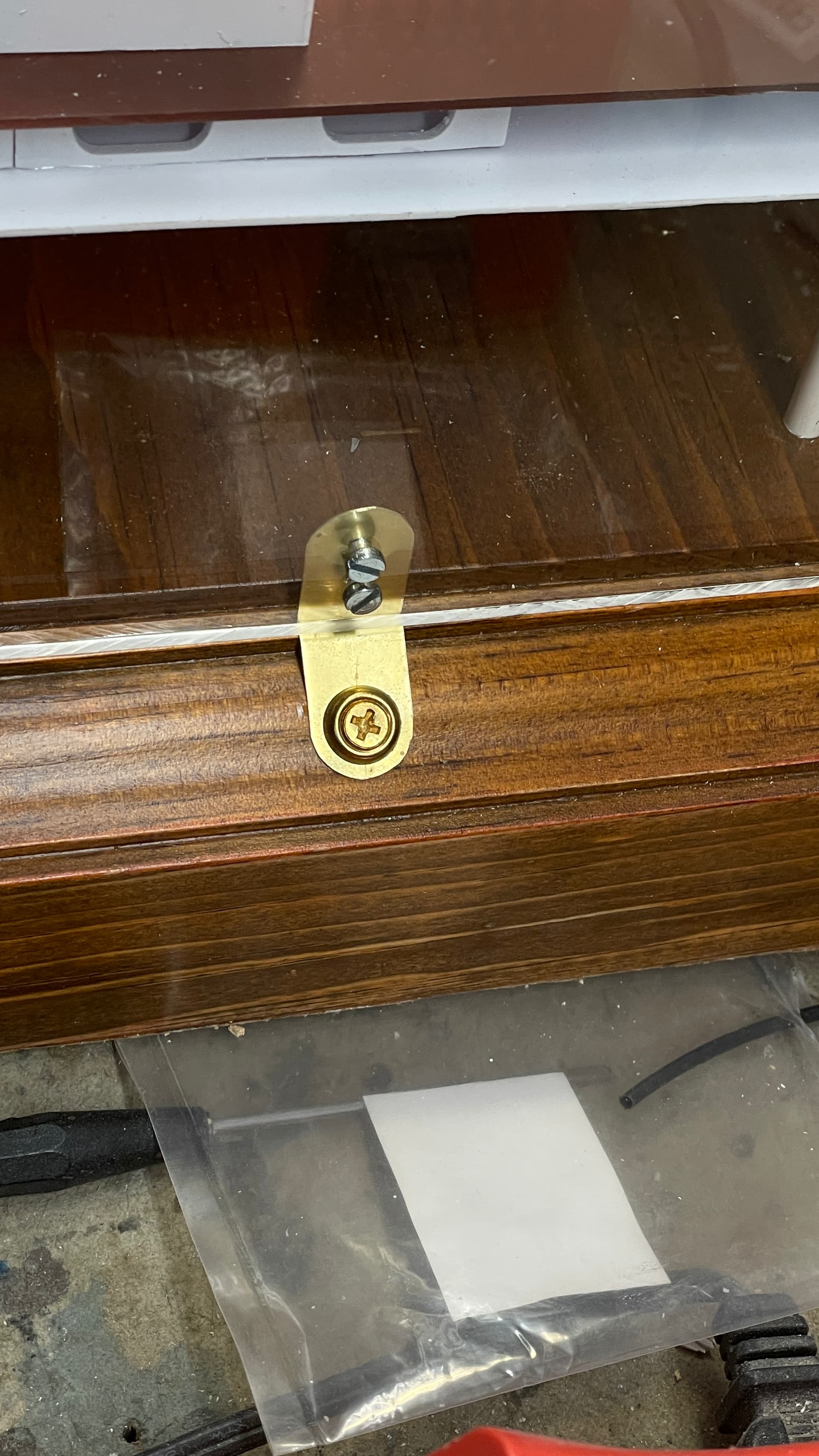
With the case positioned properly, I drilled the pilot holes for the flat-head brass screws with dress washers. Came out nice and neat.

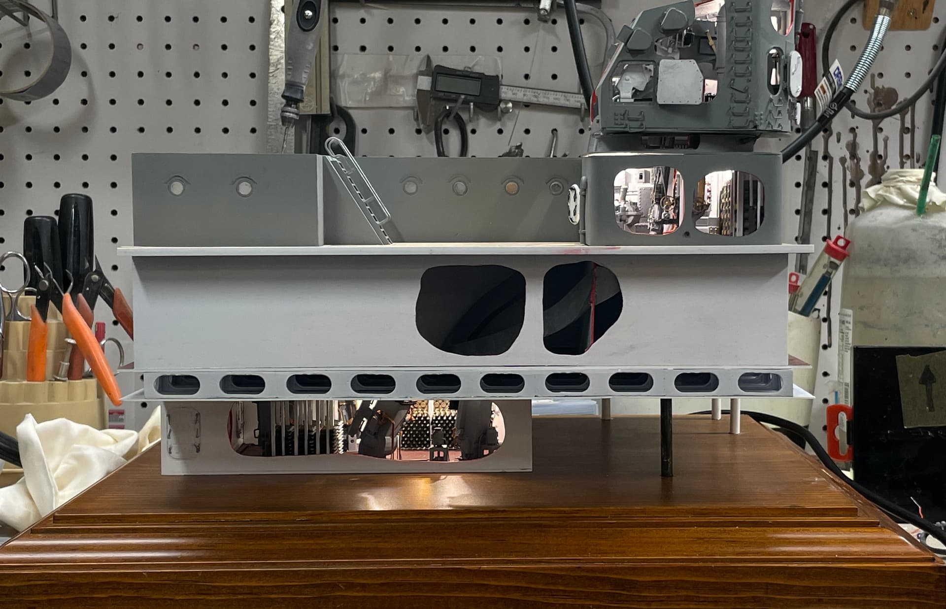
And with the case on.

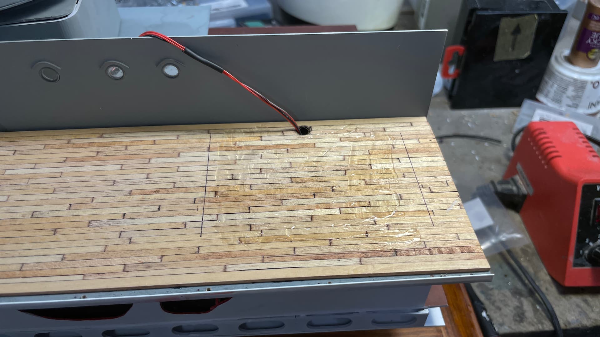
With the case fastened, I was able to tip the model backwards and terminate the light leads. I had passed the GH/UHR leads done the conduit tube before gluing in place.

I bought some very small gauge ferrules from Ferrules Direct for the 32 gauge wire I use with LEDs. These protect the delicate conductors and make connections into Euro-style terminal strips must more secure.

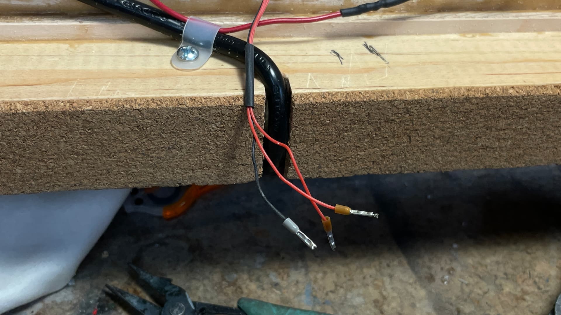
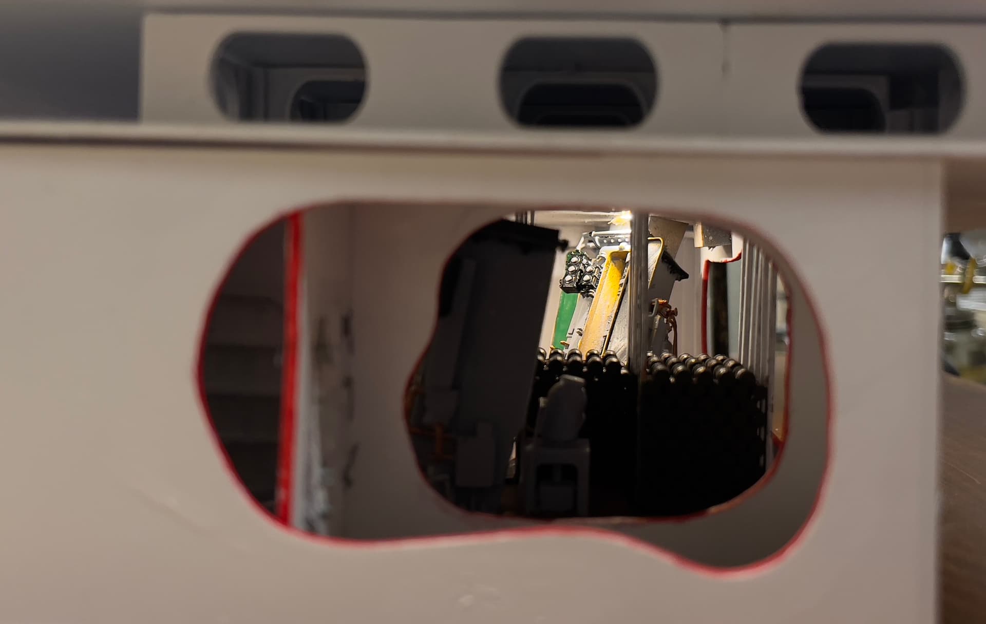
Making the connections only took a few minutes. Then I tried the lights and they ALL WORKED! Excapt for one thing… the lights in the magazine were very yellow, like high pressure sodium lights. Oh darn! I never took off the tiny pieces of Tamiya masking tape I applied to protect the LEDs from painting. The magazine is very difficut to reach now, being set way back.

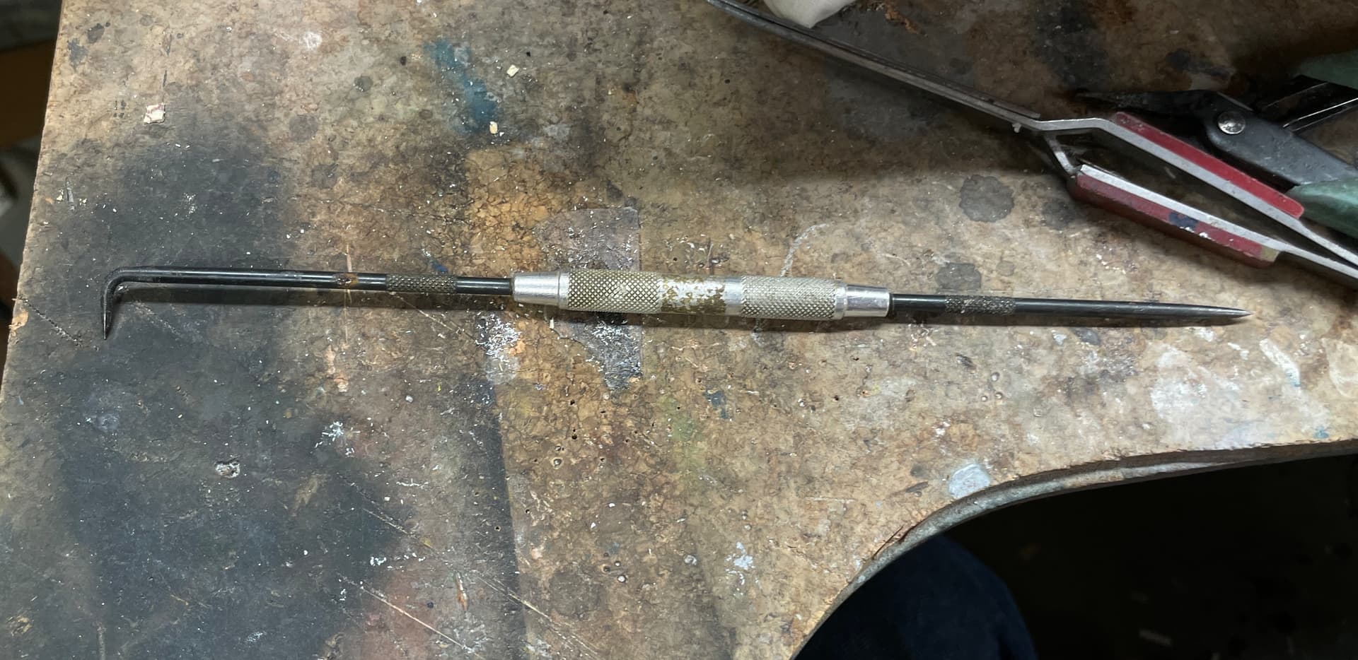
Using this long machinist’s scribe, I was able to reach them even in the powder room and remove the tape from the lights.

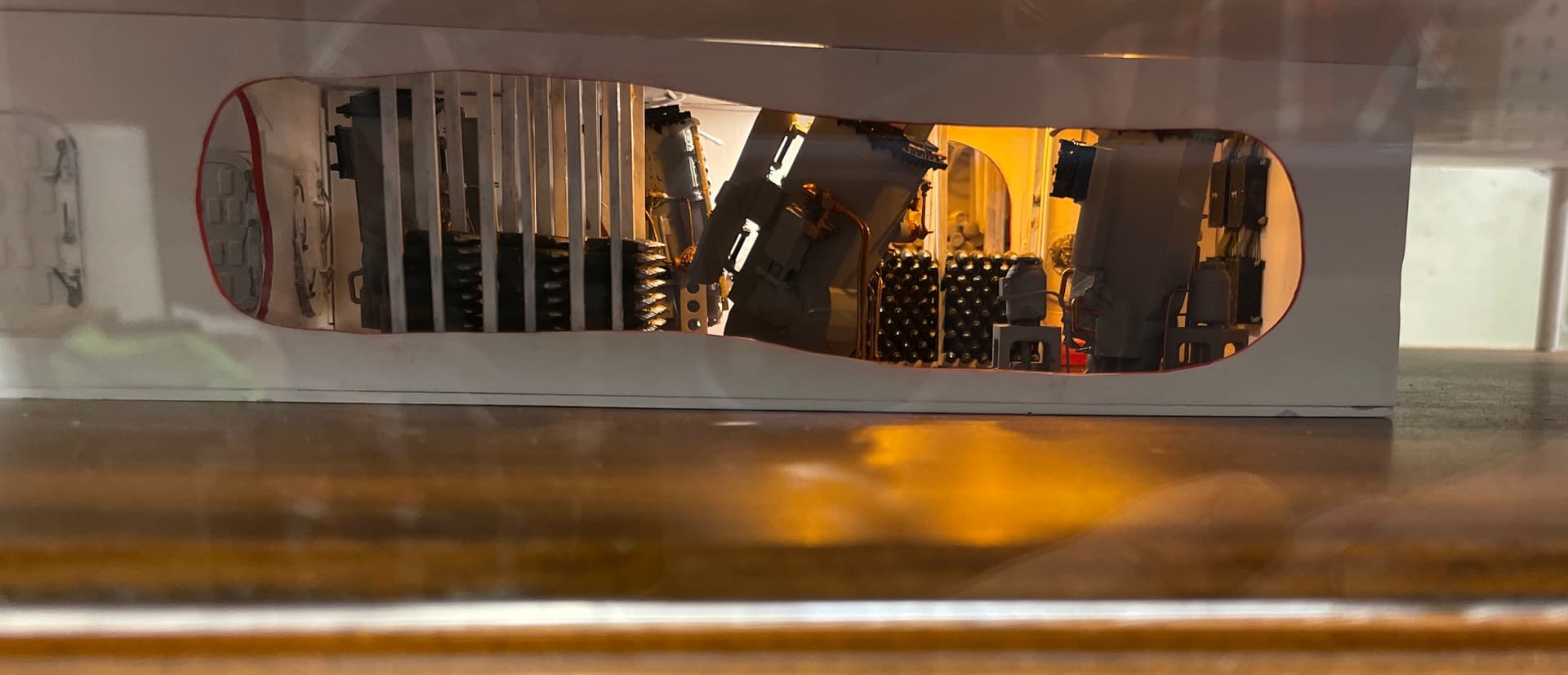
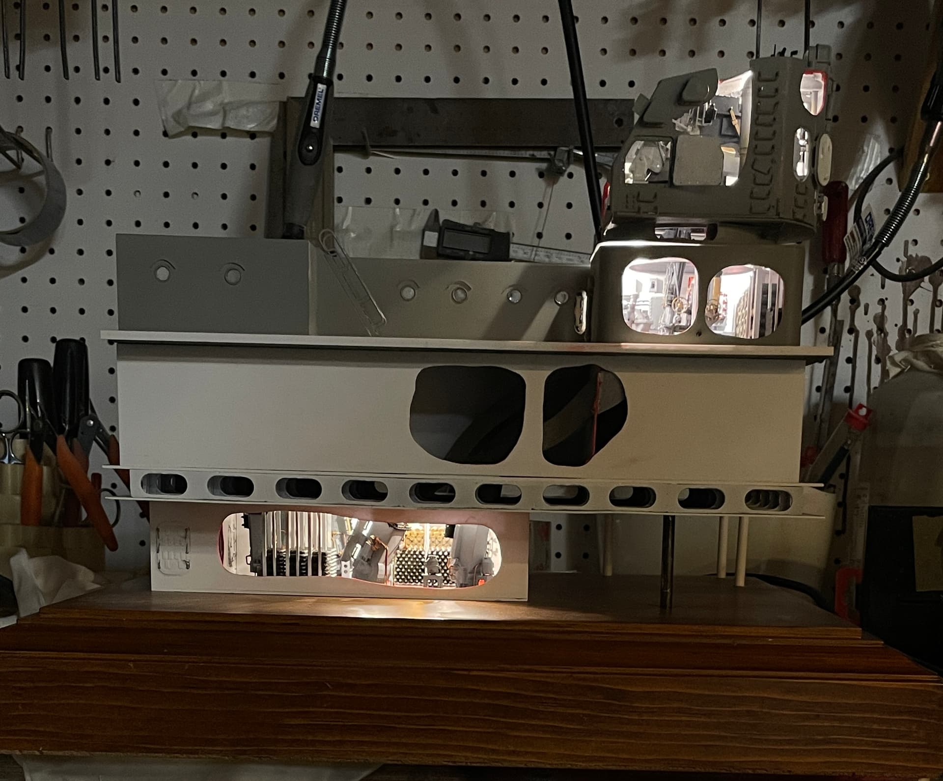
That was today’s panic moment. With the tape off, the lighting was excellent.

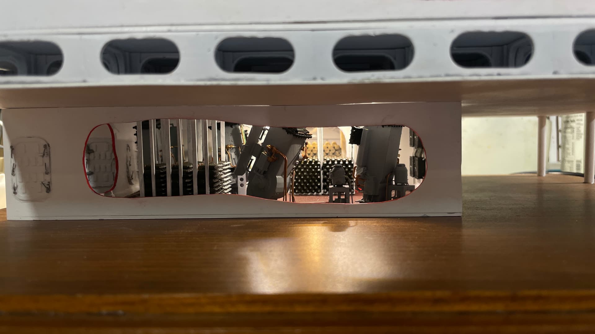
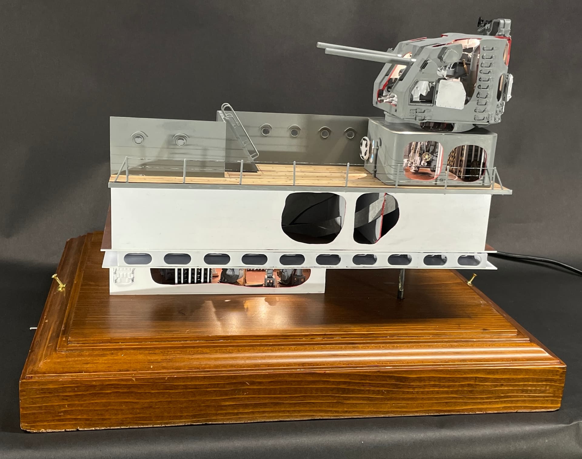
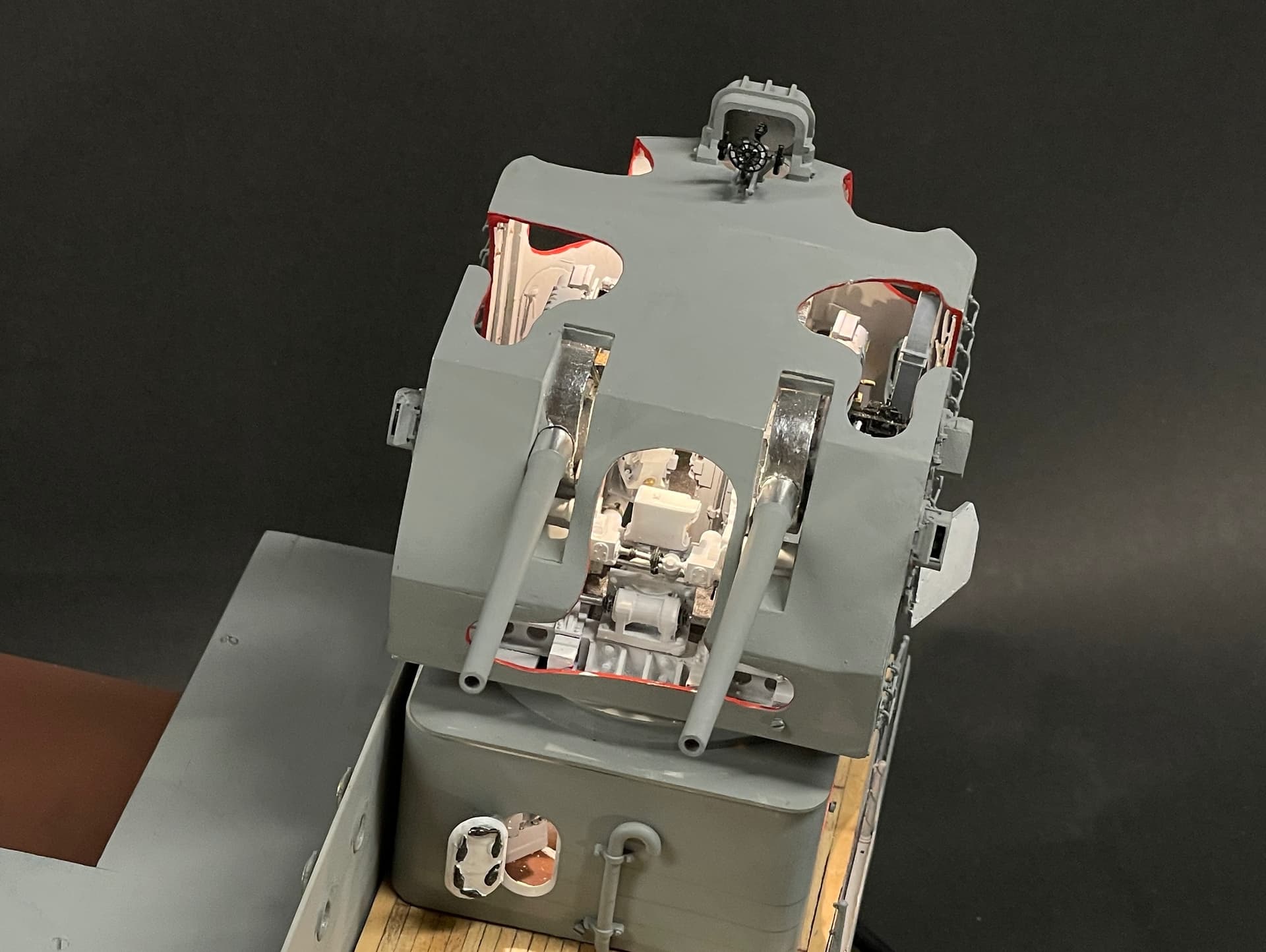
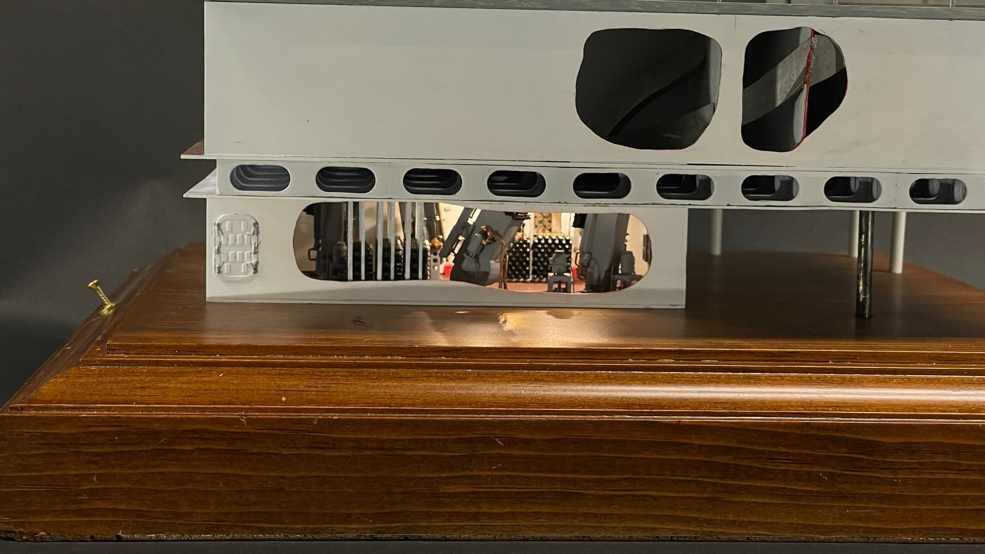
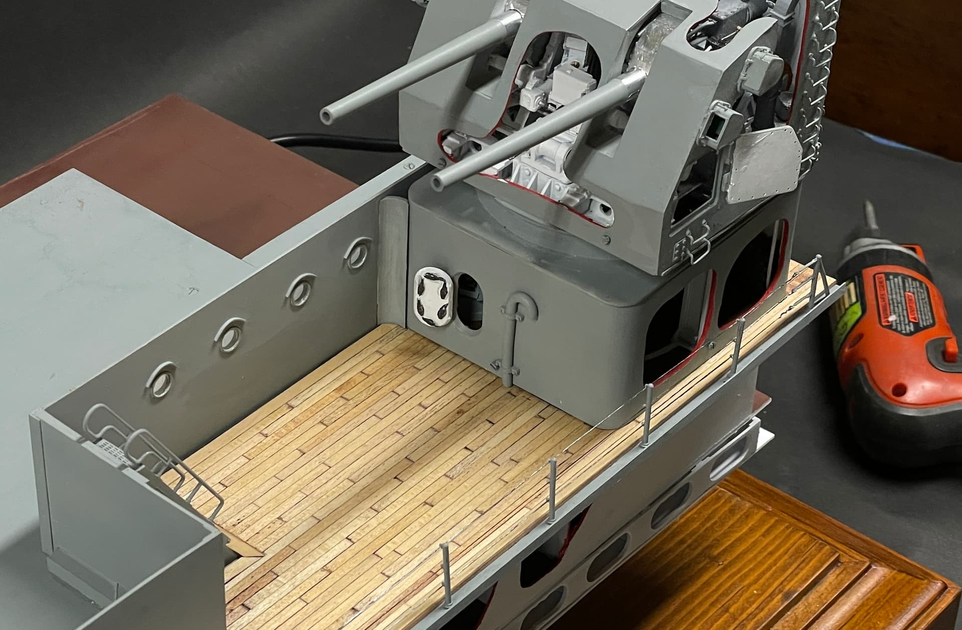
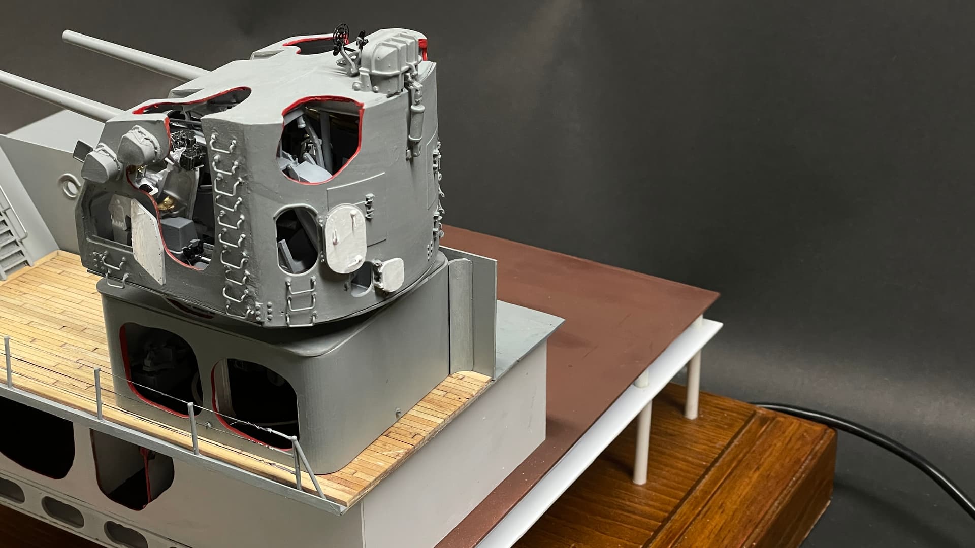
Looking from the side you can see the front faces of the those complicated hoists which I spent so much time designing, printing and painting.

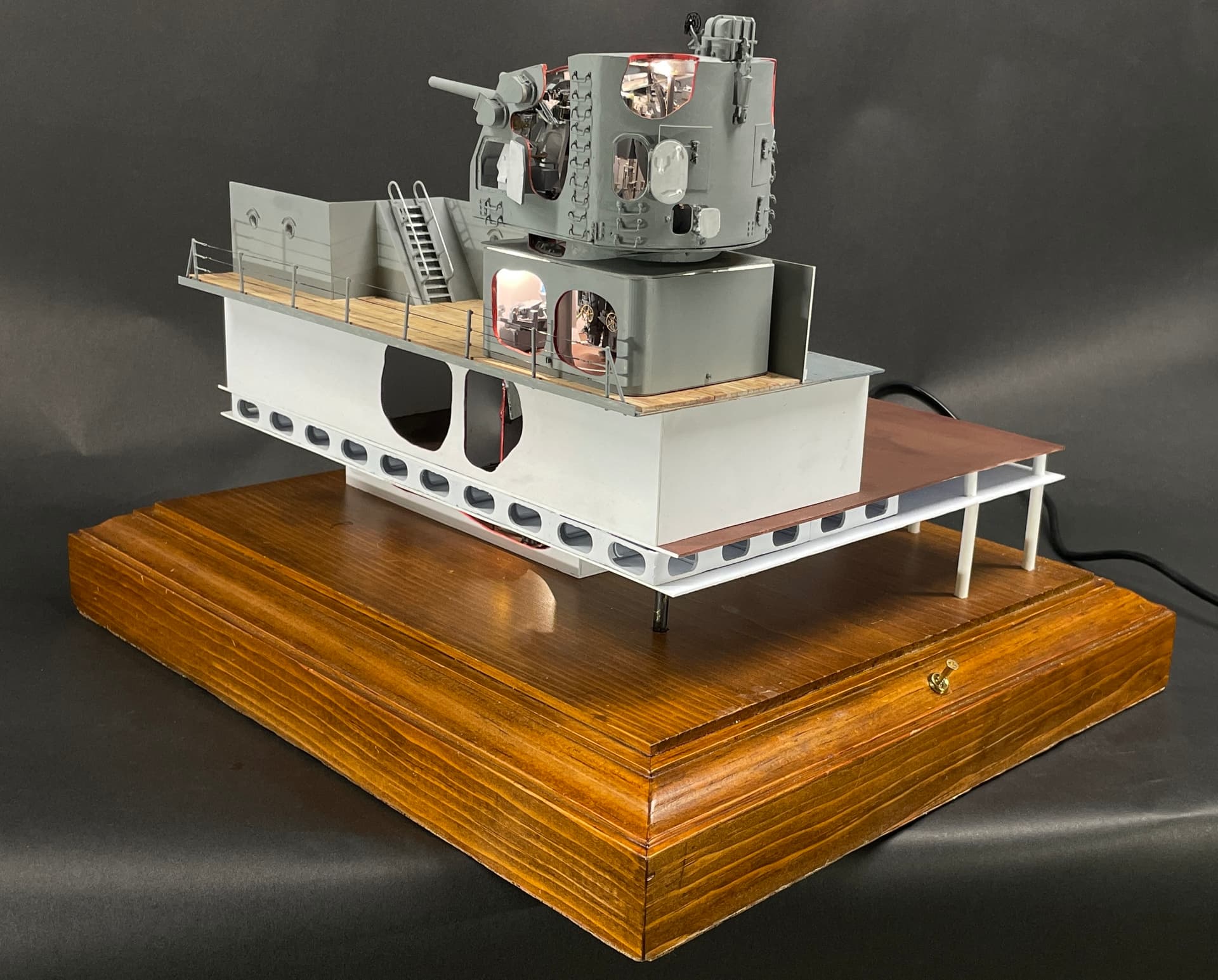
I took some more pictures with the room lights dimmed and bright to see how it looks. I’m not all that happy with the light leakage at the UHR’s roof joint. With the bright lights inside I can see that it’s caused by the vertical beam still being a little too long and keeping the roof from nestling down. Nothing I can do about this now. I kept shortening them, but apparently not enough.

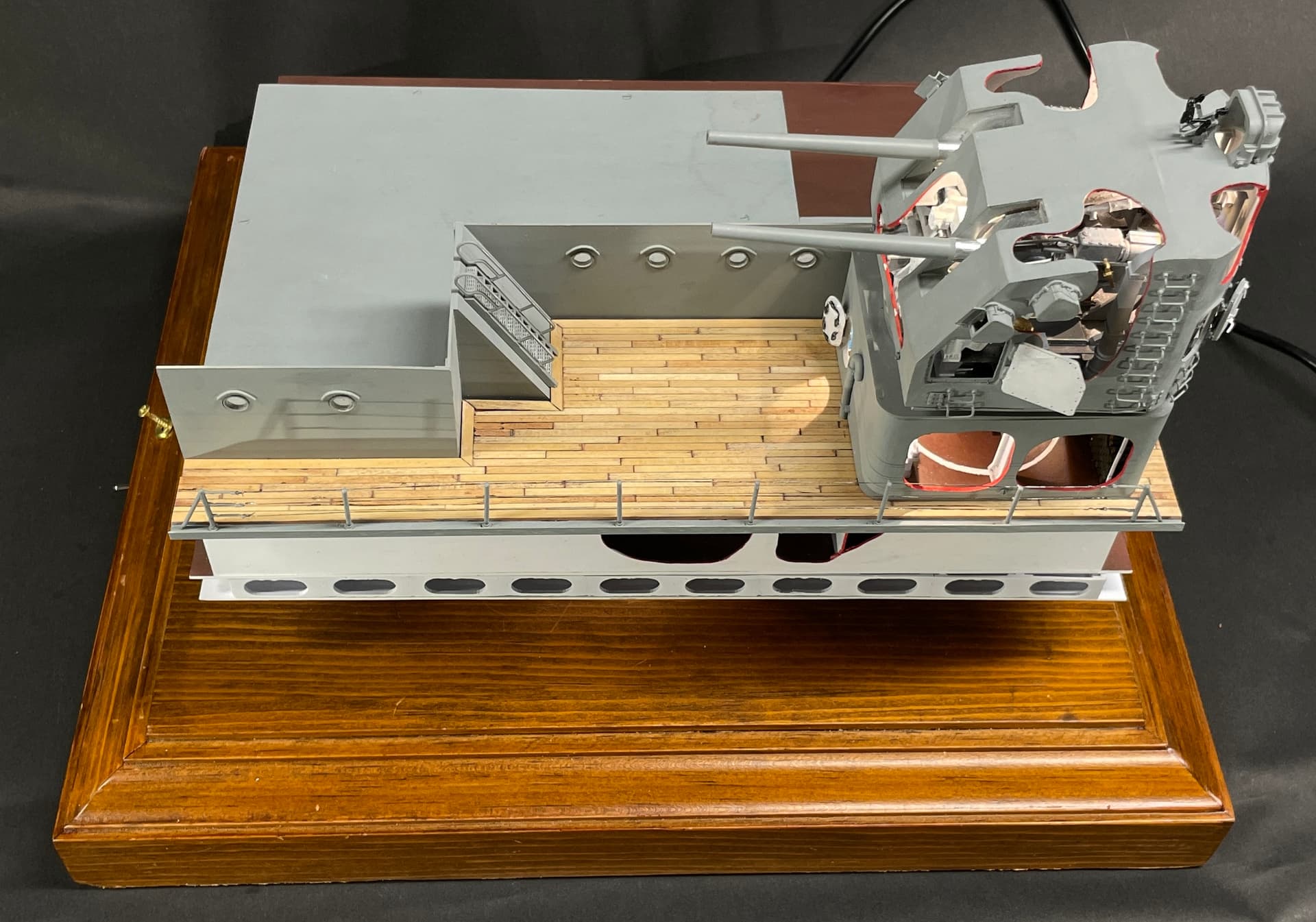
All that was left was the railings. I didn’t have much time before my 5:00 quitting time, but I got them strung. I only have to trim the excess E-Z Line and paint. The stanchion holes are sized perfectly and I didn’t have use any cement. They were all a nice push fit. I broke one turnbuckle, but I had already strung the first line and it was all CA’d so removal could be a problem. I am going to live with it. Actually, you probably would only need turnbuckles on one end of the run.

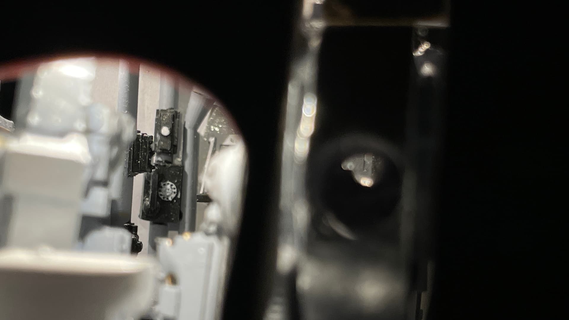
I took this image looking through the cutaway at the GH front and took a picture of the telephone dial. I sent the image to Ryan and he wondered why I didn’t paint in the numbers. He’s a kidder…

On Monday, I finish the railing and go around one more time doing a any cleanup/touchup and the model will be finished!

The AV program is done too. I have to purchase the digital picture frame to run it. Since I now have some time, I can order it, install the program and debug it before delivering it to Ryan.

I will take some beauty shots next week that will resprent the As-Built Builder’s Photos.

I will do a final wrap up and “Lessons Learned” discussion when it’s finished.

8 Likes

Myles I should save this until you declare the project finished, but for me it’s been one of the most enjoyable and entertaining ones ever, and my vote for Best of 2024 even though we’re not even halfway. Brilliant doesn’t even come close :trophy:

3 Likes

Thanks, and here are the Really Done Pictures!

Thanks Guys! Today’s a big day. I’m declaring it DONE! While I’m saying that, I’m printing out one last part. There are curved transition pieces from the ship’s bulkheads to the UHR corners. I may not use them because putting them in risks making mistakes and mess when the model is really done and clean. I’ll how well they fit and then decide.

Having spare printed railing parts, I removed all the initial E-Z Line rails, and replaced that broken right end stanchion. I also reinforced the very delicate joint between the turnbuckle and the stanchion with Bondic on both ends giving some more heft to the part. Doing it the second time went much faster than the first. I harden the tip of the E-Z Line with thin CA and then slice the end to a sharp angle to facilitate getting it through the stanchion eyes. I painted the stanchions and the outer waterway trim Life Color Haze Gray and then went over the E-Z Line with a fat headed Molotow Chrome Pen. I’m now at ease about that rail. I didn’t like having it screwed up especially since I now had the time to fix it.

And now with the case on…

I have to set a date with Ryan for delivery after the ship is back at its home berth.

So… left me do an after-action report. Let’s say, a Plus, Minus, Interesting review.

Plus:

  1. 5"38 was a very complex structure which I really didn’t know if I could pull it off. The fact that I did AND that it follows so closely to my original drawings was a definite Plus.
  2. The challenge to display the layers in roughly the correct geometric relationship to the real ship came out well. The magaizine’s offset from the gun is very close to prototype distance.
  3. Creating the AV program to show details of the model that aren’t readily seen was a good solution to the problem. Thanks to Bryant for the idea, and the acceptance of it by Ryan.
  4. When the Takom kit was out of stock, I really didn’t know if I could proceed. The gun house’s geometry, the shape and delicacy of the guns themselves had to be solved for the model to work. My skills had progressed to the point where I thought I could scratch-build all of it. Clearly, that was true.
  5. I am not patient, but I am very persistent. Making five versions of the complex front mechanism proved that point.
  6. My acrylic case-building skills continue to evolve. I’m not perfect yet, but I’ve come a long way.
  7. Managing LED light installations are getting easier and more predictable.
  8. Screwing the decks in place was a good idea and more positive than gluing them all.
  9. The wood deck came out terrific. I’m glad I chose to do it.
  10. Having two models now being displayed in the real ship is a life goal achieved. When I was offered a place in the captain’s cabin of my Missouri model, but couldn’t get it there on my own, I thought that was the first and last chance to have something displyed where it would exist after I’m gone. Through the effort I make to communicate all this stuff to folks all over the world is the reason that I was able to contact Ryan Syzmanski. The rest is history.

Minus:

  1. Unhappy with alignment of upper hoists. When I reglued the units after they had broken loose, I didn’t pay enough attention to this. Most (or all) of the viewers probably won’t notice, but I know
  2. I chose to not create the Splinter Deck Lattice so it stretched all the way across the Splinter Deck. This created a very squishy cantilever that I need to reinforce with plastic posts that ARE NOT on the ship.
  3. If I did it again, I would split the gun house down the middle and leave half off fully exposing the insides. It would have shown more to the viewers, although may have been less interesting where viewers have to pay close attention to see what’s going on inside.
  4. Still haven’t figured out the best way to make those snaky hoist trunks. Messing with them at the very end could have crashed the project.
  5. Some parts, like those tiny turnbuckles, were just too frail and I should have done something different.
  6. Even with my foresight of installing guns last and how to handle the sight telescopes, the telescopes did not work out well. If I did it again, havind half open would make that problem go away.
  7. More light is needed at the very front of the Magazine to show off the hoist side facing the viewers. I could have installed an LED aimed at the cutaway to do this.

Interesting:

  1. I know know enough about the main and secondary armament systems of the Iowas to be a docent. If we still lived in the Philly area, I would volunteer there.
  2. Watching my relationship with Ryan change from casual, arm’s length to full colleague was fun and rewarding.
  3. Because of my contribution to the Big J and being able to have that amazing private tour of the bottom was worth all the effort.
  4. It is franky, fun, building models that no one else, anywhere, has ever constructed. The icing on the cake is doing them well enough to be displayed to the public.
  5. Having been a model builder for 70 years, it is wonderful to be well-enough, have enough cognitive strength, and the creativity to do the best work I’ve ever done.
  6. It has been a great pleasure sharing all of this with you.
10 Likes

Absolutely stunning Myles. Not sure anyone else could have pulled this one off.
The BattleScale Collectica Show

2 Likes

This is just incredible! The amount of time you’ve put into this is worth it IMO. The attention to detail and masterful CAD work really makes this piece pop. Congrats on finishing!

Colin :grin:

2 Likes

Well done Myles - I really enjoyed following this.
I’ll have to visit the Big J and see it in person when all are available.
Cheers- Richard

3 Likes

Thanks guys. Ship should be open to the public in time for July 4th Weekend.

I will probably be delivering the model at the end of July.

2 Likes

Another amazing build Myles. Really great stuff - thanks for all the detailed posts in your build thread. Really fun to follow along.

Superb build and display of engineering prowess… :+1:

Thanks for all the wonderful thoughts!

I decided to do just one more thing. I drew, printed and now fit the transition pieces between the superstructure bulkhead and the UHR. It bugged me that I hadn’t done it. Tomorrow I’ll glue the two of them in place… very carefully.


And painted (not glued)

So… tomorrow it will be completely done!

7 Likes

These will be the last posts on this topic until I deliver the model in late July.

It’s now OFFICIALLY DONE with the additional of the transition pieces. I am not happen with the final result. My test fitting seemed tighter than the glued-in part. Don’t know how that could happen. The glue film was quite thin. It still works, but I really wanted it flush. I screwed the case back on and it’s never coming off (unless something breaks).

Until the next time, it’s been great sharing with y’all!

I now posting my Takom AH-64D build again at Takom 1/35 AH-64D Longbow Start-to-Finish Build - #27 by Builder2010. I hope to see some of you over there.

6 Likes

These will be the last posts on this topic until I deliver the model in late July.

It’s now OFFICIALLY DONE with the additional of the transition pieces. I am not happen with the final result. My test fitting seemed tighter than the glued-in part. Don’t know how that could happen. The glue film was quite thin. It still works, but I really wanted it flush. I screwed the case back on and it’s never coming off (unless something breaks).

Until the next time, it’s been great sharing with y’all!

I now posting my Takom AH-64D build again at Takom 1/35 AH-64D Longbow Start-to-Finish Build - #27 by Builder2010

8 Likes

Aloha,

Wow!! I just discovered this thread.

What an incredible build! Thank you for your attention to detail and thoroughness. It is a masterclass in design and construction as well as the mechanics of the gun system.

The New Jersey has always been special to me as my grandfather served on her during WW2 as a machinist’s mate. One of his jobs was making stops and cams so the various guns wouldn’t shoot the ship.

Happy Modeling,
Zon

3 Likes

This is some stunning, AWESOME work! Really impressive, thanks for sharing it with us.

The P2V-5 model along with the 5"38 project were delivered successfully to all parties. Larry was totally satisfied with his plane. I also learned that his crew got the “Best Crew Award” in 1961. This apparently is a big deal. He was the plane captain and besides handling weapons he also served as flight engineer. I will start working on the stand tomorrow.

I Spent three hours at the Battleship New Jersey. We were able to drive right up to the ship just steps from the elevator on the pier.

From there we (my nephew and I) were able to bring the model directly into the Officer’s Ward Room Lounge where the 16" model also resides. This avoided carrying the model down a ship’s ladder to Ryan’s office as we did with the first model. At that time, Ryan didn’t have a final place for it.

I spent time in the lounge talking with Ryan and other docents from the New Jersey. They were very happy with the models and had lots of questions about their construction.

From there we headed to Engine Room #3. #3 is only partially lit as it is not on the public tour route. Engine Room #2, however, was, and we should have started there. We did get there later, but by that time my phone was just about out of juice. I was using a new 3D scanning program, Polycam, which is an energy hog. I did get some scans, but I’m not so sure how valuable they will be. My nephew took about 100 pictures as well. The success (or failure) about this project is going to come down to the quality of drawings I find at the National Archives.

Ryan gave me a wonderful book “A Visual Tour of the Battleship New Jersey” by John M. Miano. John created a beautiful work showing details that I didn’t even have when doing my models. I contacted the author and we’ve shared some communications. I suggested we collaborate since I need all the help I can get doing a 3D model of the engine room. He told me that the drawings he found had blurry details. After further probing, I learned that these WERE NOT the original drawings I’m expecting to examine, In fact, he was unaware of sets of originals at the Archives. That lifeted my spirits. Right now, my wife and I are thinking about a trip to Washington DC in October where I can review the drawings.

Right now, the selected spot is on this small end table. I originally thought to have it next to the 16" model on the bookcase. This may not work because the base is deeper than the bookcase and it sticks out over the edge. We were unable to put it in final position on the bookcase becasue the 16" model is screwed down. It may still end of there. It’s Ryan’s choice. We were waiting on an extension cord to get its lights on.

Here I am explaining something about its construction showing images on my iPhone to one of the docents.

Walt, our guide was scrutinizing the model. He was a boilerman on a Forrestal class aircraft carrier. He knew his stuff! The only problem with having the model so low is having to get on one’s knees to peer inside the magazine. The kids will love it.

​You can see the 5"38 base extending out past the bookcase edge in this image with me explaining something to Ryan Syzmanski, the NJ’s curator. It may still end up there, especially if the bookcase can be moved away from the wall a little bit.

The engine rooms are reached from Broadway. This is the widest, longest and straightest passage in the ship. It connects all the propulsion spaces and magazines and is on Deck 2. The boiler rooms and magazines are reeched directly through passages, whereas the engines rooms are on deck lower and reached via ship ladders in side compartments. Broadway’s walls are lined with damage control stations. It has a heavy beam lining the ceiling where 16" projectiles can be moved from turrets at the ends of Broadway. Sections of the beam are removable at watertight doors to seal the spaces.

This is the hatch down to Engine Room #2.

The engine rooms are massively complex. There is no place where you can visualize the entire space making it very difficult to use images to lay out the space. I believe I can successuflly model the specific operating units. I am not so sure about modeling the room’s structure and the piping. Even with over 100 pictures, it’s still very difficult to discern what you’re actualy viewing. I’m not a novice with machinery and understand what I see, but it’s still going to be hugely challenging.

Engine room #2 was well lit. The diamond plate flooring is not how it was during wartime. Underneath is a grating floor. Diamond plate was used for better foorting for public visitation. I believe I can print grating and will use it, if I can. i know I can print diamond plate. The foreground ladder is the one leading from deck 2. The engine rooms occupy 2 levels: Deck 3 and the First Platform. On the left side of the image is the Main Reduction Gear and Low Pressure Turbine. In the center are the degaussing generators, and on the right is one of the two auxiliary turbo-generators that produce ship electric power. Engine room #2 is air conditioned and the open duct is seen on the right. Engine Room #3 was NOT, and it was hot and smelly. All that was lacking were screaming turbines and lots of electric pumps. It was a hearing protection area when alive. This view also shows some of the original floor grating behind the ladder.

This is a detail shot of one of the Turbo-generators showing just how complex the model could be. Modeling all the insulation that wraps all the hot areas is not going to be easy. It may require other modeling techniques such as hand modeling with epoxy putty. Lots of decisions coming.

8 Likes

Man, that was quite a journey! And one that paid off extremely well! What you pulled off is beyond doubt second to none… Being on public display, it will be able to amaze people for decades to come… Thanks for taking us along on your quest…

2 Likes

An athlete’s life goal could be getting into and winning in the Olymipics. A musician’s could be getting inducted into the Rock and Roll Hall of Fame or selling a million records. Model makers’ goal could be to have their work displayed in a museum. To that end I am very honored to have reached this goal and having it happen before I’m not here any longer. Lots of museum models are donated by survivors.

When I missed my chance to have my Missouri in the battleship in Pearl in 2012 I thought I missed my opportunity. Now having two models in the New Jersey and possibly one more, was a very nice surprise. Instead of gathering dust in my home and wondering what my heirs will do with them, I now have models that will be cared for long after I’m gone. It doesn’t get any better than this. And I am especially pleased with how all the folks that read my endless threads respond. All of this has made retirement rewarding beyond my wildest expectations.

I have friends who do not have the creative and invigorating hobby that I have. They keep working long past retirement age because they wouldn’t know what to do with their time if they stop. While I didn’t want to go into a forced retirement at 64 due to the housing collapse in the late 2000s, I quickly saw it as a time to do what I really wanted to; build models and a spectacular train layout. Thankfully, we had the financial resources to do it, and I have recieved minimal compensation for some of my work to help feed the “habit”. I also started writing.

I hated writing as a student. Of course that’s before being able to do it on a computer. My cursive was illegible, my hand cramped up, and it was just drudgery. I would freeze looking at a blank piece of paper, so I avoided it. But my work as a training professional required writing, and lots of it. I got better at it. Then with keyboarding and the DELETE key, I was able to get words down fast like my brain works. I’ve been published many times and have written thousands of words on the forums on which I contribute. I get great feedback and especially like it when people credit me for getting them started doing something that they were hestiating about. That makes it all worthwhile.

And I apologize for waxing so philosophic. If you’ve read this far, thank you.

6 Likes

If you having seen this, check out Ryan’s latest New Jersey video. He said he was going to put something out and he’s a man of his word.

4 Likes

Sweet… He does look quite uncomfortable to be on camera.
It is a pity that you can tell where the footrungs took a beating… :frowning:

1 Like

He shouldn’t be. He’s done many of these.

I was a little surpised at the ultra closeups. There’s more amiss than those pesky foot rungs when you zoom in that close. With my nre Elegoo Saturn 4 Ultra, I could print the entire gun house as a single part saving a lot of fussing. The mistakes prove it was hand made…so there’s that.

1 Like