5"38 Cutaway Turret Complex; CAD and 3D Printed

The end is near… in a good way. The nameplate is finished and ready for pickup. The plexiglass is ordered and will be ready on Friday. I got the 2nd deck compartments glued up and ready for paint. I had to modify the wood decking. I’m reprinting a modified ceiling beams, and changed my strategy for the hoist trunks.

Here’s the fully built 2nd deck compartments. I added corner bracing to help hold it square. It’s rather flexible. It won’t be when fully glued to the decks on top and bottom, but I want it to be stable as possible, so that goes well.

I’m adding mounting blocks for the styene armor deck below, and the wood main deck above. For the styrene armor deck, I’ve glued styrene 1/4" sq. stock. For the wood main deck, I’m going to glue in 1/4" sq. basswood blocks using CA, so I can get a better adhesion to the wood decking.

After further analysis, I changed the positioning of the 2nd deck structures which changed the shape of the main deck. The cutout portion in the right rear was now too small. I’m good at doing “Board Extending” and had not one chance to do it today, but two. A twofer if you will. When I measured for the first extension, I hadn’t positioned the cabins properly. I needed to add more. Luckily, I had more of the ply, and used epoxy to hold on the biggest part, and then med CA with accelerator to glue the smaller piece. I filled any gaps with CA and then went back with Bondic. When all was hardened I sanded it flush. When finished the repair will be invisibe.

I had to make relief cuts on the lap bracing so they cleared the styrene compartment walls.

Here’s the modified deck properly fitted on the cabins. I also did the cutaways on this structure. The reason for the cutaways is just to show the pathway for the ammo hoist trunks. I’m not doing any detailing of these various compartments. They are not the focus of the model other than to show that the magazines are not directly below the gun mounts.

Things are moving quickly. I have to put in the lighting for the magazine before I get any further. I changed the scheme for the hoist trunks. Just like on the big gun model, getting the hoist part to thread through all the decks and bulkheads was just not working when I mentally constructed the model. As in the big gun, I’m separating the hoist into pieces that will glue in seperately between the decks and buikheads. The viewer doesn’t care if they’re actually contiguous, just that they’re there. For their passage through the Splinter Deck lattice, I’m just going to remove the lattice completely, rather than try to cope in a precise path. You won’t see it and it greatly complicates the installation.

There’s still a lot to do, but I’m on a roll and all the critical path items are on track. There could still be nasty surprises, but hopefully not as heart-stopping as I had with the final asembly of the big turret.

5 Likes

Work continues.

I glued in the screw blocks in the 2nd deck structure and then drilled and applied small, flat head, brass screws. I’m not going to use any glue to hold the parts together. This way, it can all be disassembled should some catastrope happen. I got the lighting installed for the magazine, and that was a significant step. I’m ready to do the painting of the remaining structures and building the real wood main deck. That could take a couple of days. I need a full day to build the showcase, and at least a day to bring it all together. Tomorrow I will build the power supply board. There are only four lighting circuits to be powered.

I was originally going to glue the styrene Splinter Deck floor to the Magazine, but seeing how well the screws worked on the main deck, I chose to add wood blocks to the magazine upper wall edges to capature the screws. I won’t be doing this for the splinter deck, but will use epoxy instead. This part of the model doesn’t have any functional components and should never have to be disassembled.

It took me literally three attempts to layout the lighting circuit on the Magazine celing. I was working with the structure upside down on the work bench and just couldn’t get the orientation right. My first attempt was completely wrong. My second only partially wrong. Finally, I got it correct and was able to first use 3M transfer tape to adhere the thin ply to the styrene and then apply adhesive copper foil ciruit runs. The fun didn’t stop there.

I tested the Surface Mount LEDs before installation and again after soldering them into the circuit. I mark the + and – polarity so I can solder them in correctly. Works great, especially when I pay attention to it. In this case, the first LED was in correctly, but I reversed the second. So they worked when I applied power individually, but didn’t when I applied power to the circuit. LEDs are Diodes, and therefore, block current from the opposing polarity. In my desoldering I overheated them and they were scrap. I replaced them and my test rig failed. I had salvaged some CL2N3 LED driver chips from a previous project, which I had tested and they worked okay. My test rig has an unprotected 12 VDC lead for protected LED circuits and another with a CL2 in the line to apply 12VDC at 20ma for the unprotected LEDs. It was failing and over-drove the circuit blowing out all three LEDs. After redoing the test rig and applying all new LEDs, I got good tests on all circuits. With 12VDC applied, I’m limited to 3 LEDs in series since they each drop 3.3 volts. A fourth LED would be 13.2 volts which doesn’t work with a 12 v power supply.

Here’s the bare circuit. This will all be painted ceiling color and won’t be very obvious.

I used Bondic as a cable clamp and combined the negatives in parallel, but each positive circuit will go to its own CL2N3 driver in a little circuit board below the base. I scuffed up the styrene where the Bondic was going so it had more grip.

I installed a 1/4" brass tube to act as a wire conduit for these wires and those coming down from above. I have drills sharped to drill plastic. It’s a much sharper angle than standard 135º point angle. They don’t grab on exit and can drill plexiglass and down shatter the plastic on exiting.

5 Likes

Big day! It was the kind of day that gave me confidence that the model will be completed on schedule. Only had one catastrophe which I sort-of corrected. We were supposed to have wild weather, but itw as sunny and warm so painting outdoors worked fine. I had to prepare some stuff before painting. I joined the gun house shell to the base and continued working on the wiring harness.

I didn’t use screws to hold the armor deck to the underside of the 2nd deck cabins. I glued it, and I’m going to glue the Splinter Deck lattice to the underside of this part since there’s not good place to put the attachment blocks on the Splinter Deck. When the glue set it was ready for paint. I printed the now-fragmented trunks, and painted them metal color, mostly so they’re show up when people peer into the spaces to see their path.

While all this was drying, I started to put the gun house together. It just about fit, but there were still some problem areas. All of the fit problems stem from one error that I suspected, but didn’t take any action about. The sub-floor under the GH frame was too far back…about 1/16 (or more) rearward. It may have been a drawing error. Some things about the shield design changed throughout the various iterations of the project.

This error caused a lot of troubles that didn’t really appear until now. For example, it pushed the sight scopes rearward. This put stress on the sight checker’s scope, which decided to break off when I was working on another fit problem. Oh… and I also broke off two more resin footrungs. I think I’ve replaced half of these already. Getting very good at it.

The scope broke out here…

And this is what the chunk looked like. Even with my resin mix with Tenacious (a flexible resin) small cross-sections are still very fragile.

I had a spare that I used as a guide on how this thing went back together. I got it into place with Bondic, but it’s aligned poorly. There’s not much I can do about that since it’s the base position problem that’s causing the alighment problem.

I didn’t want to remove the shell to get it fit better. I had some difficulty with the screws not establishing solid threads and removing them would basically make them useless. I’m hoping that it won’t be so noticeable.

Another problem caused by the plate position: the front frame girders were sticking out beyond the base plate and were distorting the front lower edge of the gun shield. I power sanded the excess to make it flush with the base plate so the front panel was no longer distorted.

Similarly, about a 1/16" of the base plate was sticking out behind the curved rear wall. After taking this picture, I sanded that off too.

The gun house light circuit is now combined with the UHR light circuit with all the leads dressed and ready to go further down into the model. They are running down the back of the UHR, nestled into the veritcal support beam, and won’t be very visible. I joined the negative leads from both circuits since the negatives will be on a common bus.

Here’s another image of the gun house in place.

Tomorrow, I will airbrush final coats on all the parts, and do detail painting on all the various hatches. Then I’ll get to building the main deck superstructure and planking the main deck. With that the model will effectively be complete. I’m looking forward to doing this last part since it’s just traditional model making and shouldn’t cause too much anxiety. This gives me three to four more days of solid work time to get it all done. I have a couple of doctors appointments next week, but they’re not long ones.

10 Likes

Very impressive build.

Happy Mother’s Day to all for which it is appropriate!

Several things are going on. Almost done the model proper. All the major painting is done, have to finalize the electronics, and produce some more graphics. Deck to cabin attachement is nearly complete. Both the main deck to 2nd Deck Compartments, and Magazine Ceiling to Magazine are now held with screws. All linoleum is finish coated. Gun house is finally ready for joining to UHR and everthing is filled that needed to be.

However, I have a major glitch with the plexiglass. I took a small risk ordering the plexiglass by measurements given to me by my friend Bryan, the base builder.

I picked up the Plexiglass on Thursday and the base arrived in perfect condition on Friday.

When I tried the plexiglass on for size, the front/back and top were about 1 1/4" too short!!! The sides were fine. What the heck happened???

Went back to my drawings and realized that when Bryant gave me the measurements they were shorter than what I had on my drawing. A red flag should have gone up, but instead, I adjusted my drawing, and then measured the plexiglass with this new measure. That was wrong! I should have called Bryant and asked him to recheck.

I called General Rubber & Plastics here in town and asked them to cut three more piecces to the new measures as taken diectly from the (CORRECT) base and they will rush the job. If it comes in by Wednesday, I will be okay. Thrusday may not work since the acrylic cement takes 24 hours to fully cure and I don’t want to risk it coming apart during handling.

So what went wrong. Bryant is a perfectionist (like I am sometimes), but it was his error. His ruler’s end is not the start of the measuring and he forgot to add the difference. Ergo, he measured the correct base and got an incorrect answer. The worst that can happen is it cost me an additional $50.00.

I got most of the detail painting done on the three new Lower Hoists. They came out very nicely.

I masked the edges and brush-painted the linoleum color on the magazine and visible floors on the 2nd deck. And with the apparatus fitted. I may not use my roof beams. They are going to impinge on the hoists. My hoists may be a tad over-sized and my beams are definitely over-sized. Regardless, they will be hard to see.

I will call General Rubber tomorrow and get a fix on delivery. Shouldn’t take to long to cut 3 peices of 3/16 plexiglass. They mill it will a CNC machine so the edges are just about ready for gluing. I hit them with some light sanding, chamfer slightly the gluing edge and they’re ready to go. Should only take 1/2 hour to make the case once I have the correct stock in hand.

I really want to deliver this when we’re at the dry dock tour. It’s a perfect time to get it there with the renewed interest in the ship with all the news coverage it’s been getting. It would be great to have it sitting next to the big gun when it reopens in June. If I miss this date it will have to wait until we drive back East again, and that could be as late as fall. Meanwhile, it would sitting around here risking something bad happening to it.

6 Likes

Good luck getting that plexiglass!

1 Like

Thanks! If you can’t be good, be lucky.

Made substantial progress today, and I’m feeling pretty good about finishing the model (at least) on time. Finished all the detail painting on the reprinted lower hoists so they’re done. Built the LED driver board with 7 parallel circuits. 6 are dedicted now, but I’m thinking of adding some light into the 2nd deck cabins showing the hoist trunks and one over the overhang where I may be placing the nameplate. If I don’t put it there, it will be adhered to the back wall of the showcase.

Since I’m already paralleling some of the negative leads before they even get to the circuti board, I don’t need very many barrier terminals. I DO need a separate positive circuit for each 3-LED series sub-circuit.

The bottom is not very neat because it not really a printed circuit board. It’s more like a bread board. The positive ends of the CL2N3 driver chips is a common bus, but the output side goes to each circuit individually.

I finished crafting the final wall structure; the sample of the superstructure that resides next to the #4 gun mount. I needed to make precise holes to accept the 3D printed porthole assemblies. It’s a pretty big hole and I attempted to grind a plastic-pointed drill with the 100º drill point angle. It didn’t work and grabbed and tore my test piece. I reverted to making my “Poor-man’s Punch” scheme.

It goes like this:

  1. Grind the tail end of the drill you want to use with a diagonal flat surface.
  2. Lightly grind the diameter to remove any burrs and give a sharp edge/
  3. With the business-end of the drill, create a hole in a piece of steel, aluminum or brass that will serve as the die side.
  4. Reverse the drill in the drill press with the punch-end in this newly formed hole to align it with the drill press spindle.
  5. Lower the chuck while loose over the punch and manipulate it so it is as vertical as you can get it.
  6. Clamp the die end (over a block of wood with the same hole) and clamp the drill press table.
  7. Tighten the flute end of the drill in the chuck without disturbing the geometry. Note: the drill really isn’t symetrical and clamping it in a 3-jaw drill chuck is optimal. You’re not going to turn the drill on, just press straight down
  8. Place the plastic on the die and punch the hole.

I laid out the hole locations and scribed circles of the correct diameter to use as a guide when positioning under the punch.

This was the test!

And here was the actual run. The plastic doesn’t pull away when you raise the tool. Real punch presses have stripper plates that sit between the punch and die to remove the part from the punch. Since it’s just plastic, it’s not hard to remove the workpice.

Here were the pieces punched for the portholes.

And assembled.

And now with the portholes installed.

Notice there is a raised lip around the porthole which is exactly as I wanted it with the 0.040" plastic sheet I was using.

This is the back side with won’t be viewed by the public, but all the porthole details are there.

Tomorrow, this new stuff gets painted. And I will start on planking the main deck. Should take a day. More painting needs to be done on some of the decks. Final assembly should be on Wednesday and hopefully building the case.

I finalize the AV program, but don’t yet have the digital picture frame. You can get 15" screens for about $100.00 and I’m trying to convince Ryan to spring for this one thing.

Here’s a sample of the visuals i created for AV program.

7 Likes

Outstanding work! It was a pleasure meeting you in Louisville a few Fridays ago, and I was lucky enough to see this model up front and in person.
What is the status of the plexiglass? Will you get in in time?

The BattleScale Collectica Show

Thanks and like wise. The plexiglass was done today and as you’ll read, put to good use.

Thanks for the input. I’m using the acrylic adhesive that they sell at the plastics house. It appears to work like other acrylic cements with very low viscosity and the ability to be attracted by static charge.

The replacements were available today. I picked them up in the early afternoon and got the case built by 4:30. I’m getting better at building these things, but I’m still not great. This one has a minimum of glue where it’s not supposed to go. For that I am thankful.

Before I retrieved it, I did more detail work on the model. I installed 3/16" square stock edge thickeners on the upper superstructure to provide more glue surface when I glue it down tomorrow. I also added a corner brace to square up that external 90º corner. I then started to paint it and realized I hadn’t installed the “eyebrows” over the portholes. It’s a little detail, but I wanted to include it. I was using a very forgiving paint (Life Color), wiped it off and made the eyebrows out some very small styrene strip. I got them on and painted the part. To fully cure it takes overnight.

I also finally painted all the cutaway edges of the magazine and 2nd Deck compartment openings, and final touch up on the gun house and UHR. They’re all ready for final assembly. I used Vallejo Crimson Red, and then back painted all the red that got on the outer surfaces with Vallejo White. Both paints have good hiding qualities and the final looks very neat and trim. I’m still worried about doing the planked deck. It could take a lot of time which I no longer have. I have two days!

Then I got the case parts. I was disappointed that the replacement parts were saw-cut and not CNC milled. They were much rougher and had some chipping. I’m not complaining. They turned the job over in less than two days. They’ll suffice.

To clean up the edges some… I have a edge sanding contraption that I built when gluing up balsa skins making a very large RC aircraft 13 years ago. It’s a 1X3 screwed to a 1X4 capturing the sandpaper in between. It provides a long, square edged surface with abrasive and works pretty well. The saw marks were deeper than it was reasonable to expect their removal via hand sanding.

After cleaning up the edges as good as I could get, I determined the edge that were going to get glued and created a very slight chamfer on the inside glue edge with a sanding block. The chamfer is very small, but enough to help guide the needle applicator and promote capilary flow. Speaking of capilary flow, I was also told to use a Q-tip and coat the glue edges with cement before taping together. It helps flow into the joint.

The fellow at the plastics house also recommended removing ALL the protective film. It just gets in the way. Acrylic has a lot of static charge. It’s a problem because it will draw cement off the applicator and deposit it where you don’t want it. Another trick he told me last time was to do all the work with the assembly sitting on a damp towel to reduce static charge.

I then used two micro-fiber cloths to clean off any dirt and sanding debris. One was damp followed by a clean dry one. These cloths are fabulous! I bought a stack of 100 of them from Amazon for something around $12.00. They’re washable and worked great on the stove, cleaning leather car upholstery, mirrors, etc. And they worked great on acrylic!

I started taping it all together using Tamiya wide tape, but it didn’t have enough grip strength to hold it together. I switched to 3M Blue Tape. I put the sides together first sitting on the top piece, and then errored thinking that I had to turn it over to get the top fitted. That attempt loosened a lot of the tape forcing me to reconsider. I replaced the taped-together-walls back on the top, slide it off the table a bit and so I could apply tape to its underside, rotated it off the edge and did the rest of the sides in order.

Tomorrow starts the full-court press. If I don’t get it done, I can’t blame the Plexiglass.

I applied the glue using the last tip I received; squeeze the air out of the bottle applicator and then release as you rotate the tip into position. This way you don’t get that “spurt” when you tip the bottle oveer to apply the cement. This tip really helps making clean job.

I made a measurement error too. I made the height measure for the new long pieces 1/16" too tall. It shows up here…

The effect is to raise the ends a little off the wood base, but it’s well supported by the long sides. Oh well…

After gluing, letting it set up about 1/2 hour, I was able to lift it, put it on the base and clean off any tape residue. It came out very clean and better than my past attempts.

8 Likes

The end is nigh! I got the main deck planked in a little over two hours. I woke worried that I didn’t have enough scale wood, but I had way more than I needed. I gang cut the wood in my modified Chopper 2. I built a depth stop on this useful tool, that lacked it. I makes it much more useful. I cut the scale 3 X 2s to scale 8’ lengths. I don’t really know how long the deck planks are, but they don’t look very long.

I laid the 16" long strips on the deck to estimate how many planks I would need.

In the past when I planked a deck that had dark caulking, I laid strips of black construction paper edge-on, and then shaved the excess off with a razor. I didn’t have the paper so I tried another approach. I mixed Aleen’s Tacky Glue with black India Ink to make a jet black PVA glue. I pre-stained the planks, but after sanding most of the color was removed. The black glue make the joints dark and looks pretty good.

When first applied it looked like a mess.

And when fully planked really didn’t impress me very much.

But, after sanding, it looked pretty good. When I started gluing I applied it by brush to each piece. Later I realized that it was easier to apply it to the substrate. It was a cleaner approach and at least 2X faster.

And with a coat of clear Urethane, it looks pretty nice indeed. Tomorrow I’ll glue down the superstructure. It’s just sitting there looking pretty.

I laid out and drilled for the railings. The end stanchions have faux turnbuckles. They look good, but are very, very fragile. I’m going to rig with E-Z Line and will wait until I’m ready to put the case on before doing it so I won’t be reaching over it to do anything else.

I got the power system all button up and made a brass plate to hold the power switch. I’m not turning on the primary. Instead, I’m turning off the secondary. Everything is waiting for the wiring to come down from the model.

So… what’s left. Everything is painted and staged. I have to asssemble the layers together. Before doing that I have to populate the magazine with all of it’s appliances. I have to paint one exposed deck, that’s now white, but I want it linoleum color. I have to install the chunks of the hoist trunks during the stacking process. Lastly, I have to make the locking system for the showcase like i did with the big gun.

Meanwhile, we’re going to early vote tomorrow since we’ll be gone on primary day and I have a cardiology checkup at 1:00. Still, I’m optimitic that I can bring it all together. I was worried about the case and the planking and both are done and no longer an issue. The rest should go together pretty well. (Famous last words!)

7 Likes

My optismism was not well-placed. I came very close to finishing today, but, as usual, something in the final assembly proved much more challenging that it would have appeared. That said, I did get much done. I got the magazine finished, mounted on the base and fastened it’s roof on with the wiring led below. I got the splinter deck glued to this roof and then actually glued the second deck in place. I got the gun house and UHR joined and decided on the simplest of conduits for the rest of the wiring. But what got me was trying to install those segregated pieces of hoist trunk through the cutaway openings in the 2nd deck cabins. It was very difficult… it was getting messy… I was running out of time and I envisioned bad things happening. I gave up and will pick it up after we return. Besides, Ryan has his hands full right now and it might not have been such a good tie to bring it.

I you look closely at this image, you might pick up that I installed that first row of powder canisters backwards. I know it’s backwards because I spent a lot of time painting the yellow on the openning end of the canister and they’re not seen here. Would anyone care? No! But, it’s an indication that I was rushing. Things don’t go well when I do.

I got the little steps laind in at the base of the powder room doors and painted the mechanism steel color. I used 3M transfer tape to hold the hoists down. All the rest is held by the J-B Weld construction adhesive.

I pre-fit the stack with a couple of small screws holding the magazine ceiling and reckoned where the UHR wiring was going to penetrate the main deck. I marked this and drilled all the way through the stack with a 1/4" plastic drill bit. I then used a transfer punch to mark the location of this hole on the base. For the uninitiated, a transfer punch is a specifically-sized piece of tool steel with a center-punch point on it. They come in a set that matches a full set of drills and they’re used to mark locations using a hole as the datum. (harder to describe than used).

I drilled the base with the 1/4" brad point drill and now had a straight path for the wiring to go below through a brass 1/4" tube. The tube will be visible, but not obtrusive and will help support that very cantilvered from of the model. It also greatly simplified getting the wring done.

Here’s the punch before running it all the way down and tapping lightly with a jeweler’s hammer.

The conduit top opening fits directly under the openning in the UHR 's rear floor next to the back support.

Here’s the lead opening in the UHR floor.

I’m going to chemically treat the brass tube so it will be very dark and in the background.

My arrangement varies slightly from my original design bringing the splinter deck and cabin all the wasy forward. This changed the trajectory of the hoist trunks.

I used the plans to find the location of the Splinter Deck lattice and then to remove any interfering lattice so the hoist trunks can pass through. If you remember, I originally drew and printed openings. This all went out the window since I had slightly changed the geometry.

I made small drill marks at the corners of the rectangles that represent the hoist trunks at that posiition. After gluing down the lattic and the hoist trunk parts, they didn’t align well with the hoists themseleve and I had to position them back and to the left about a 1/4". I then removed any interfering lattice.

After assemblng and gluing the whole stack, In my agression fitting the rest of the hoist trunks the glue fell apart, but it was good it did. I was having trouble getting the middle to settle in properly. The reason was the hoist parts were about 3/32" too high and well keeping the whole center from gluing.

I broke them loose (they were CA’d) and ground off the excess on the belt sander. So when I finally glue it back together it should nestle down much better.

I glued a thin strip of styrene on the front deck edge as a scupper gutter. Needs to be painted.

This was the clamping scheme.

I finally put the gun house and UHR together with four small screws. I dont like the roof fit, but it was a 3D Printed affair and not a styrene part. I also don’t like that the UHR hoists are tipped forward and not centered in the space. Can’t be fixed now. That ship has left the dock.

As much as I wanted to finish it for this trip, we’ll be making other trips and, as I noted, messing with the hoist pieces was getting messier after each attempt and leading to something bad to happen.

So what’s left? I have to get the hoist trunks in and clean up the mess inside those spaces. I have to connect the field wiring. The railing needs to be built as the last thing. I have to mount the name plate and the one graphic on the rear case wall, and make the lock clamps for same. Instead of the construction glue, I’m going to use the J-B Epoxy designed for plastics. It needs to be secure. I screws the magazine to base with self-tapping screws so it’s not going anywhere.

Everyone have a nice Memorial Day and I’ll be back after that.

10 Likes

bearing in mind those few issues you had on this update, that really is a hell of build. Now its all coming together, the time and effort has proven to be well worth it. Superb engineering :+1:

4 Likes

Finish line is close! This is my second one of your extensive builds (first being the Iowa class turret). So fun to follow your process. I’d love to see one of these in person some day.

3 Likes

The nice thing is all you have to do is visit the ship. Even when I’m gone, it should still be there. I found out today that we’re getting a private tour with Ryan. I will document it and share with all. All I needed was one more work session…

4 Likes

Hello gang!

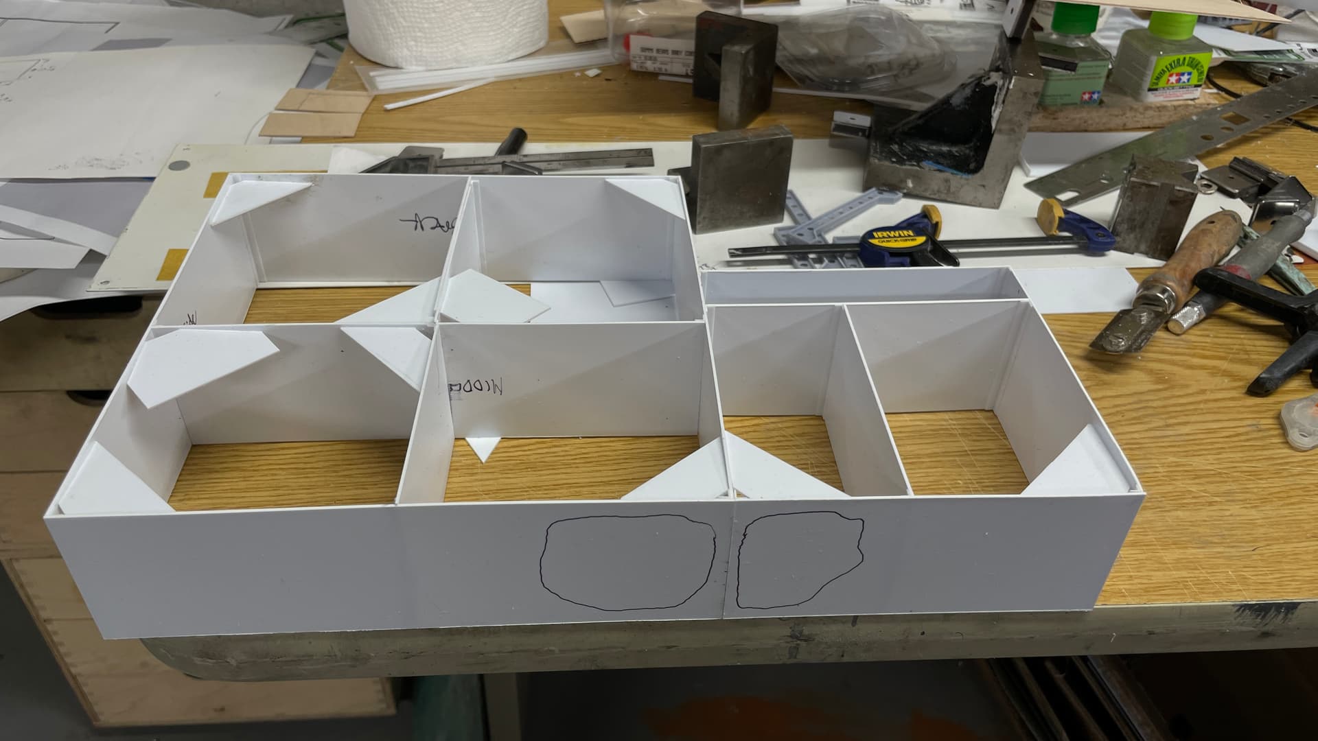
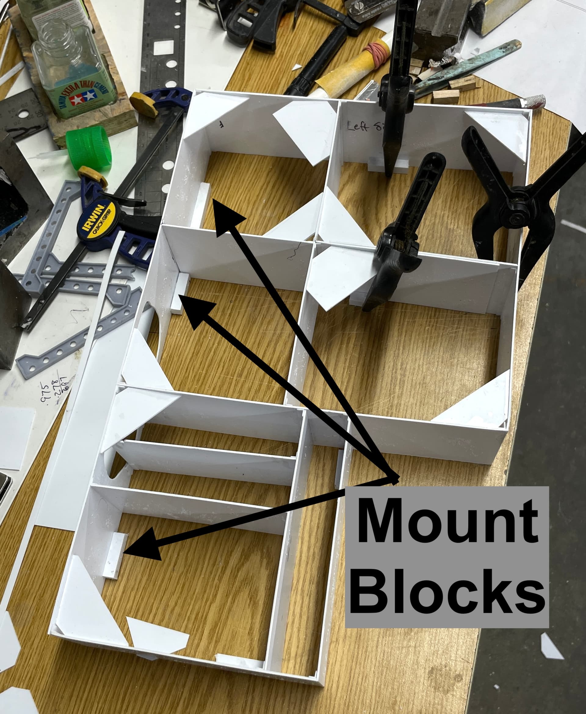
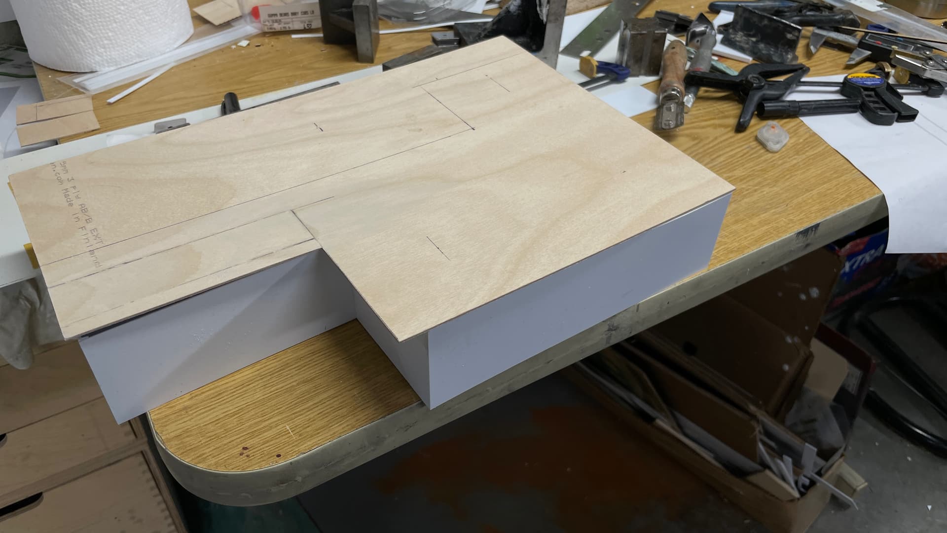
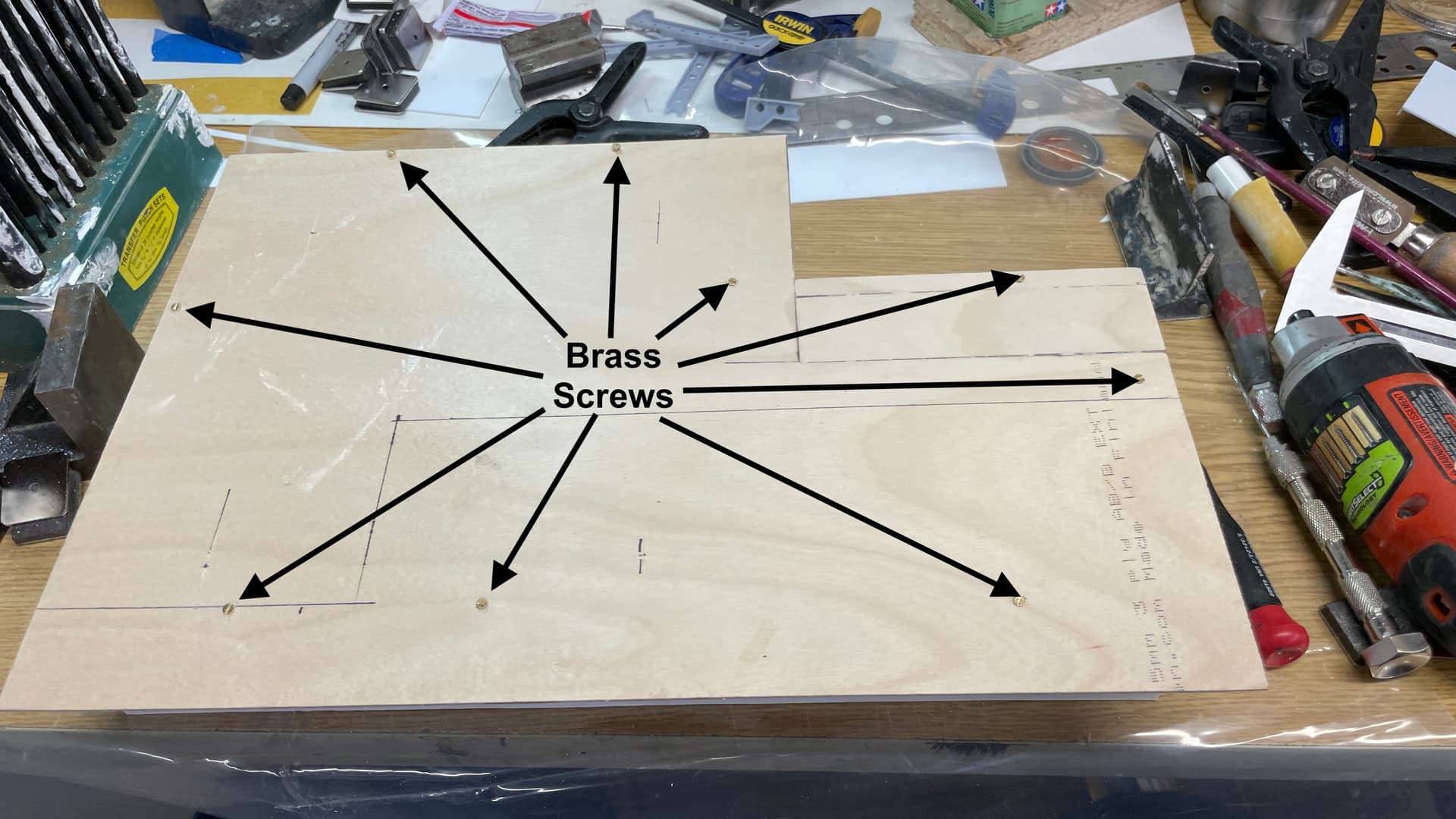
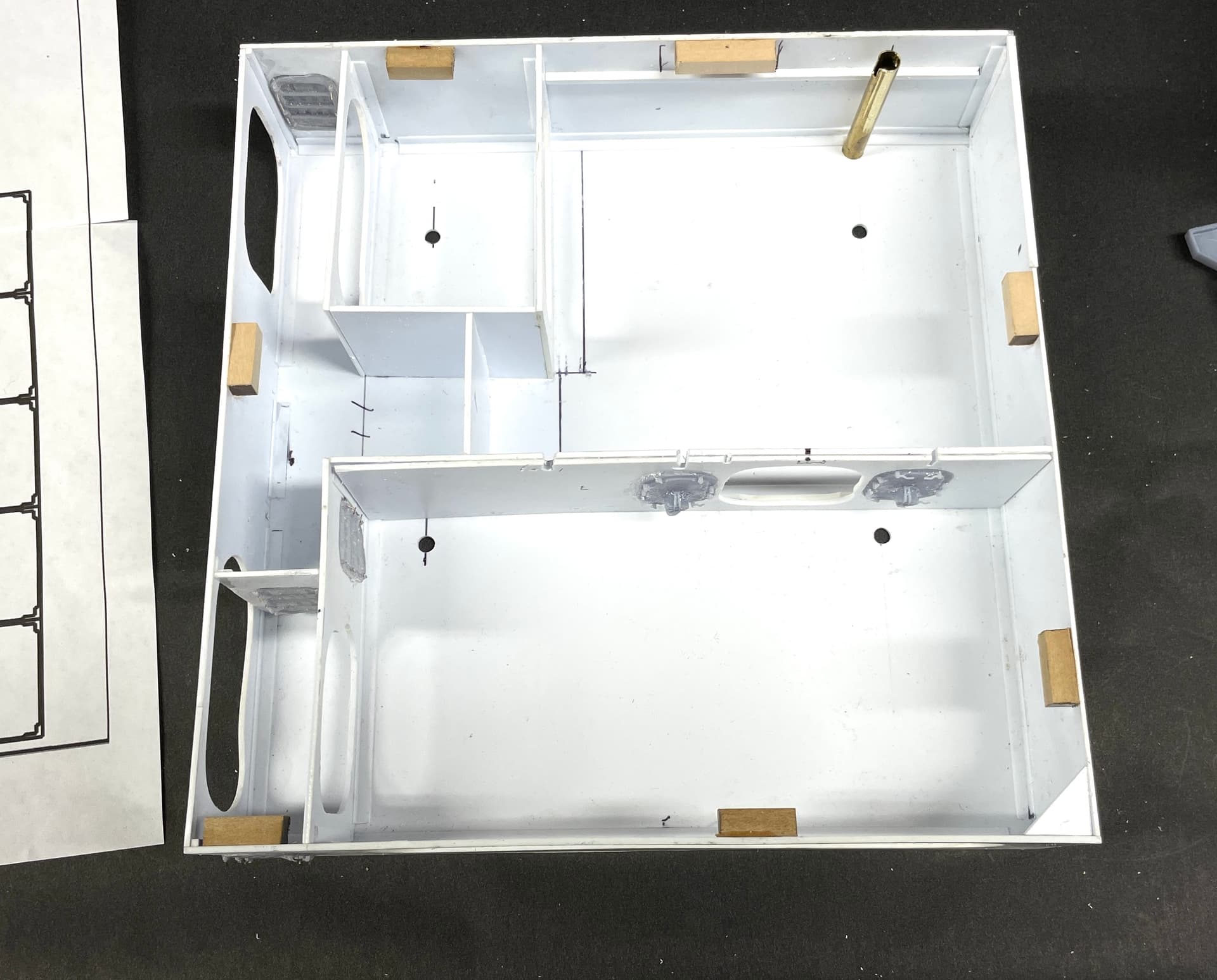
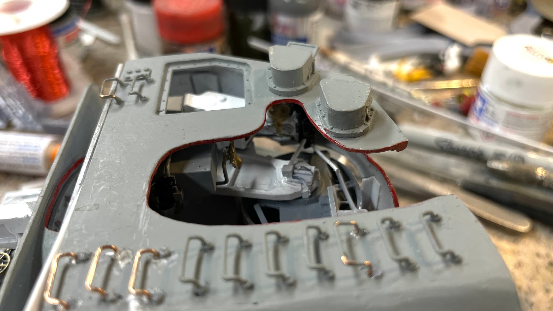
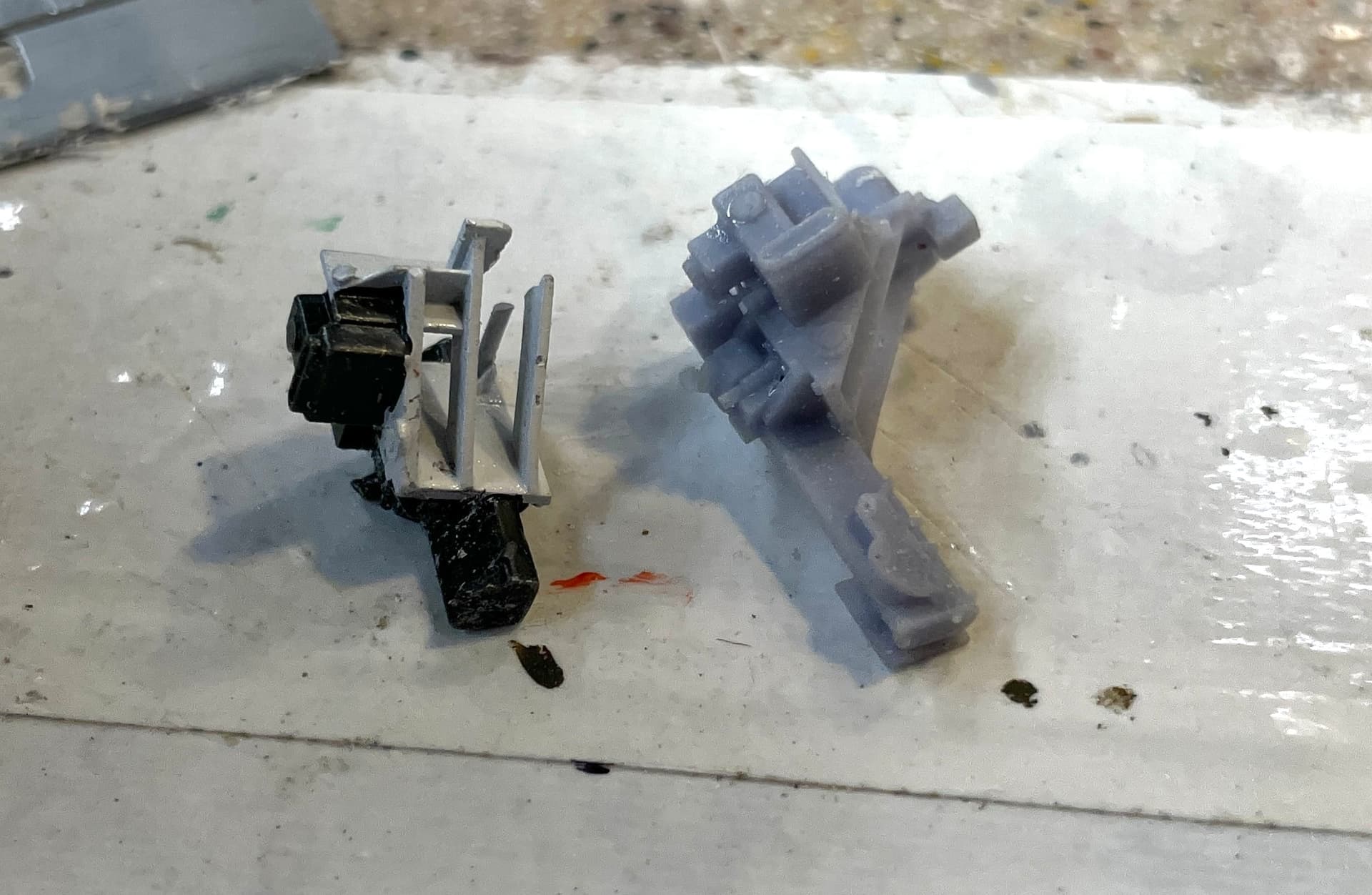
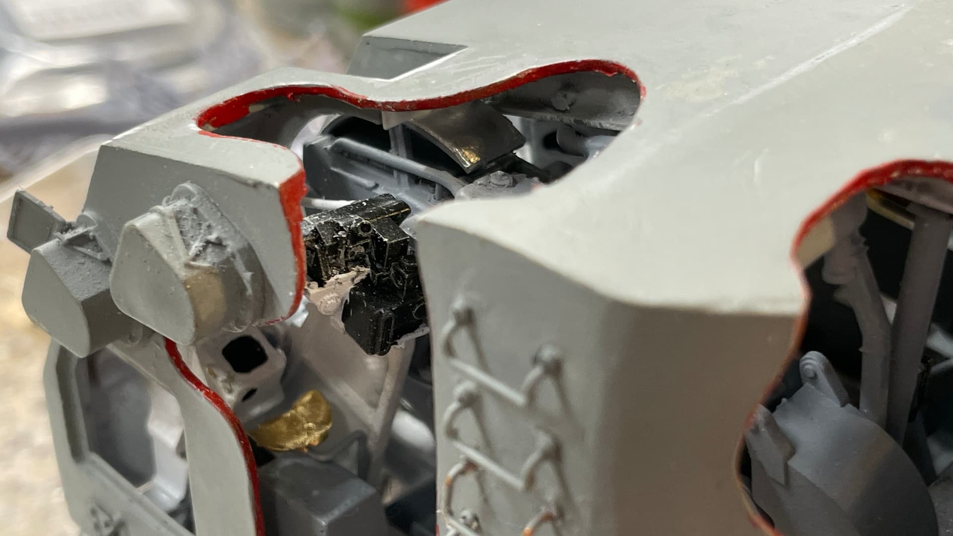
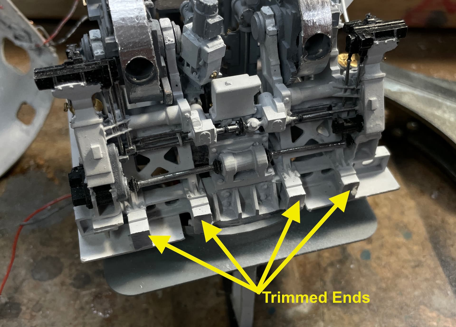
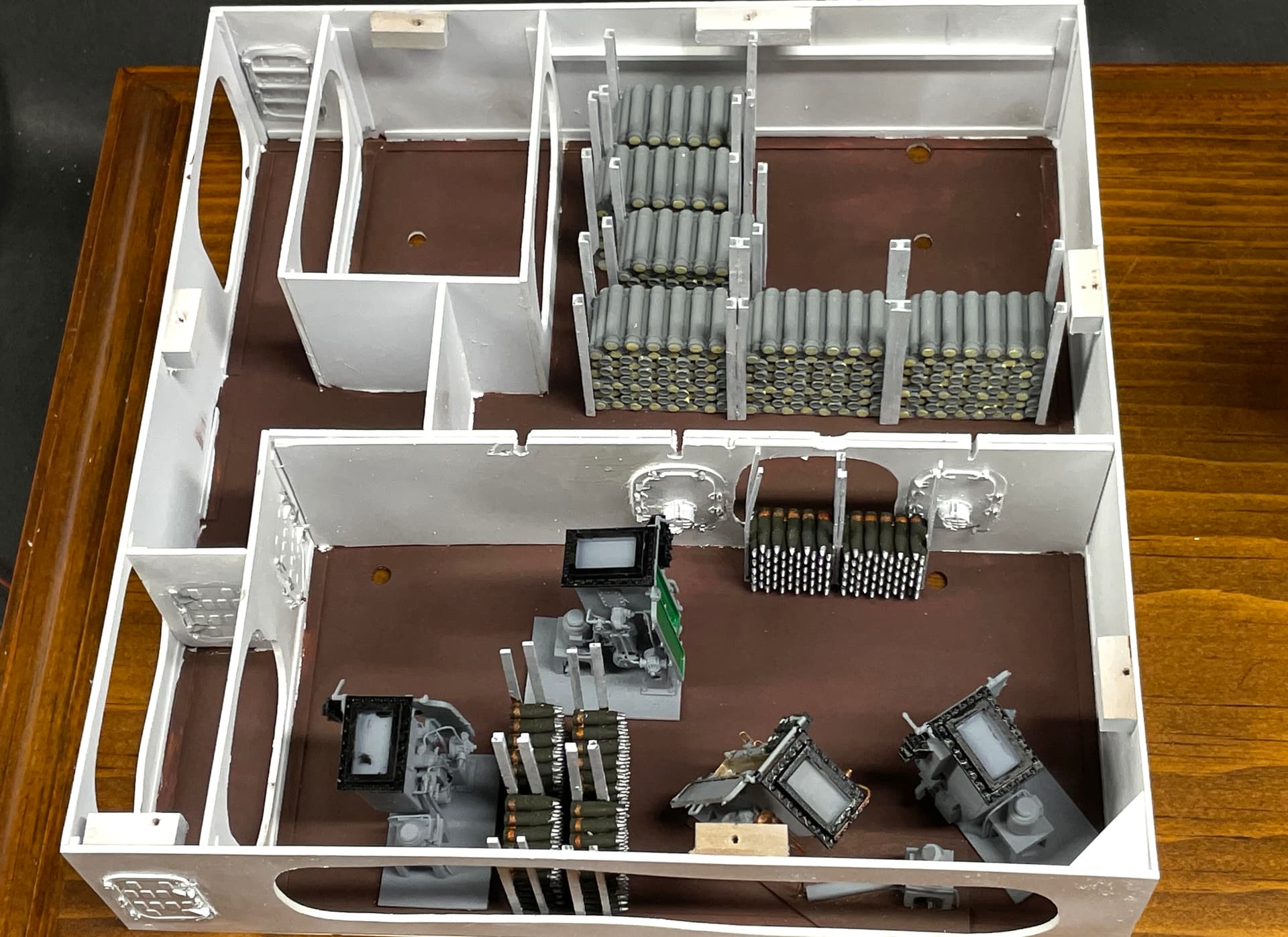
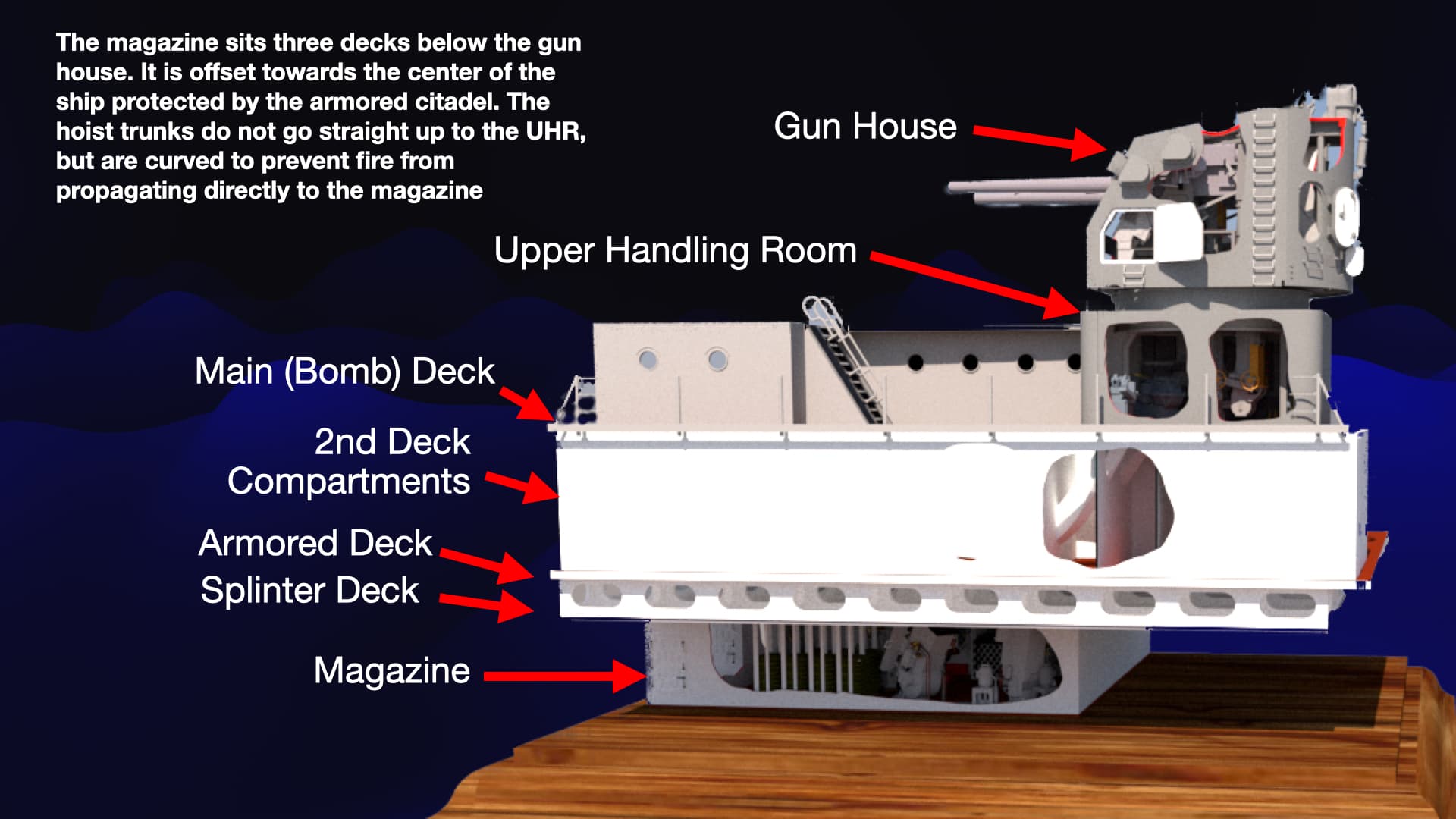
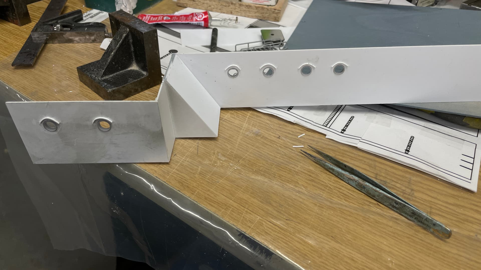
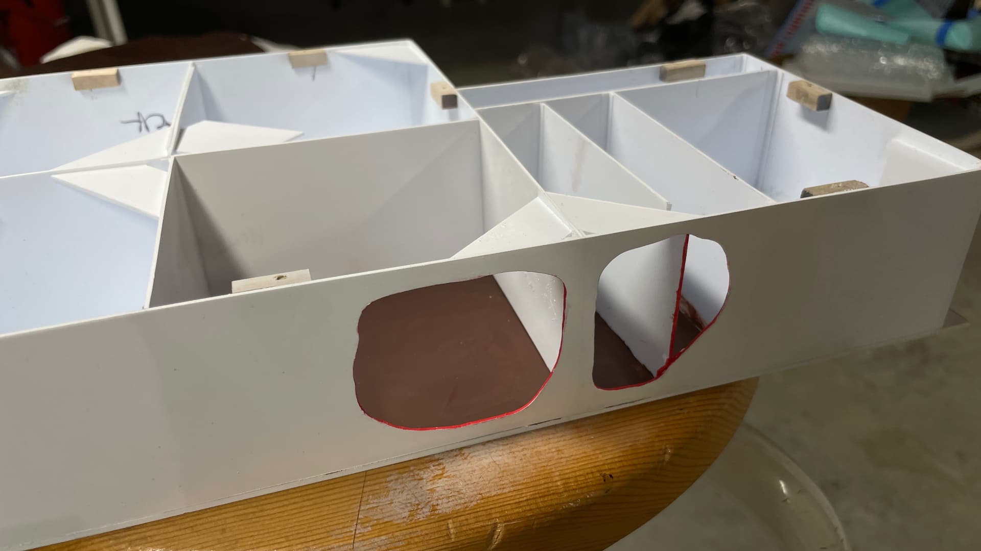
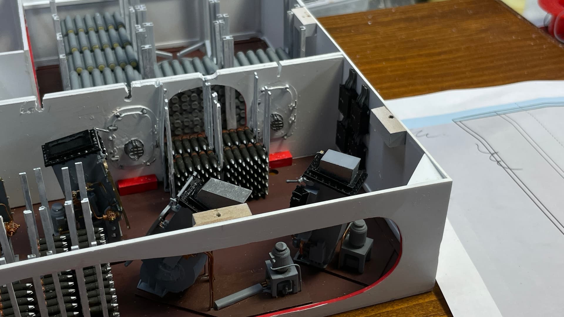
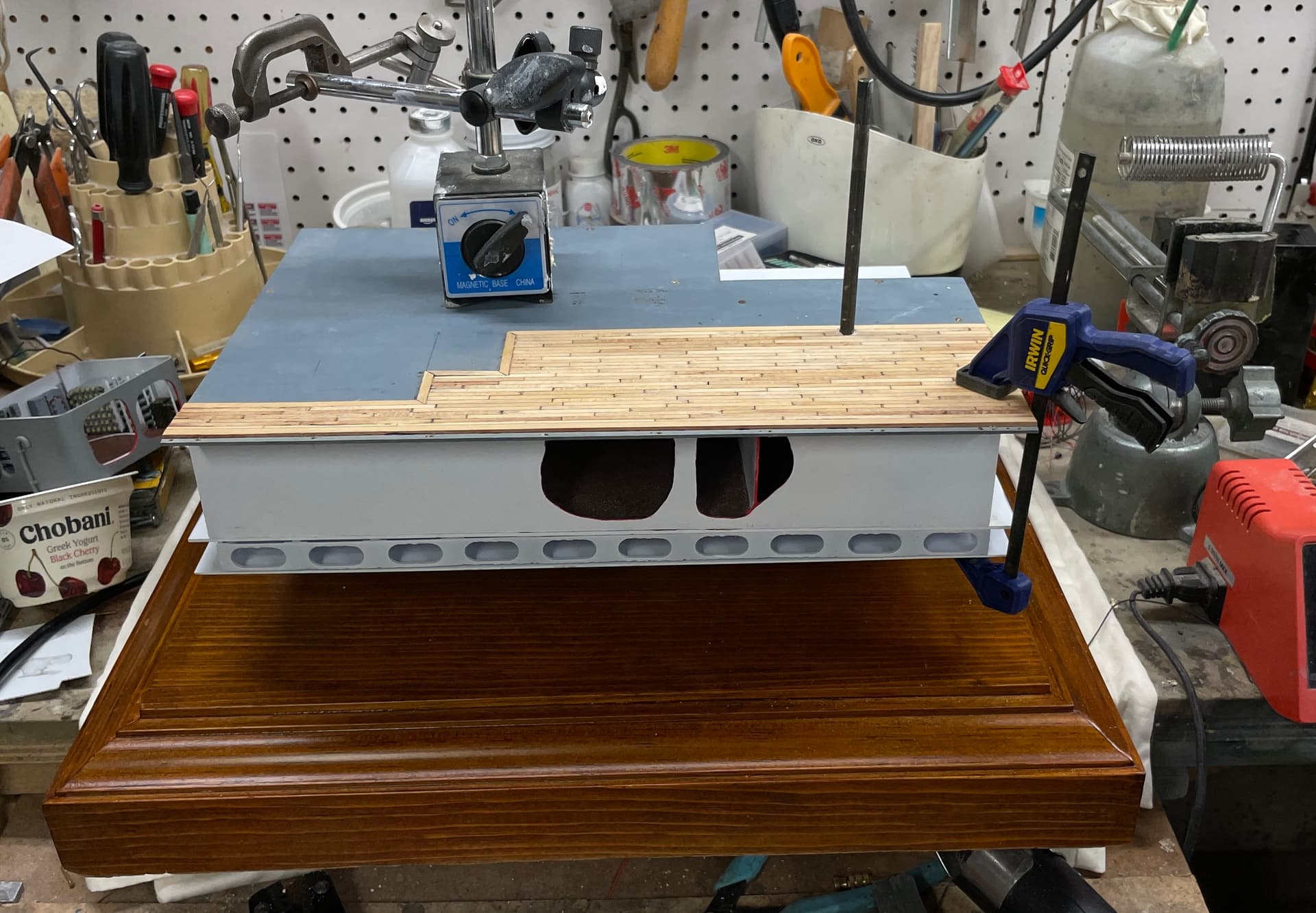
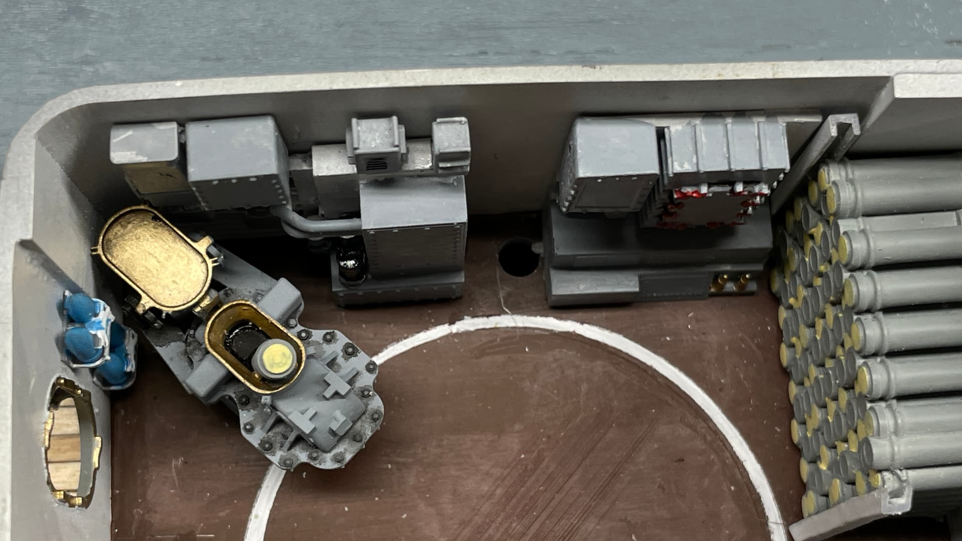
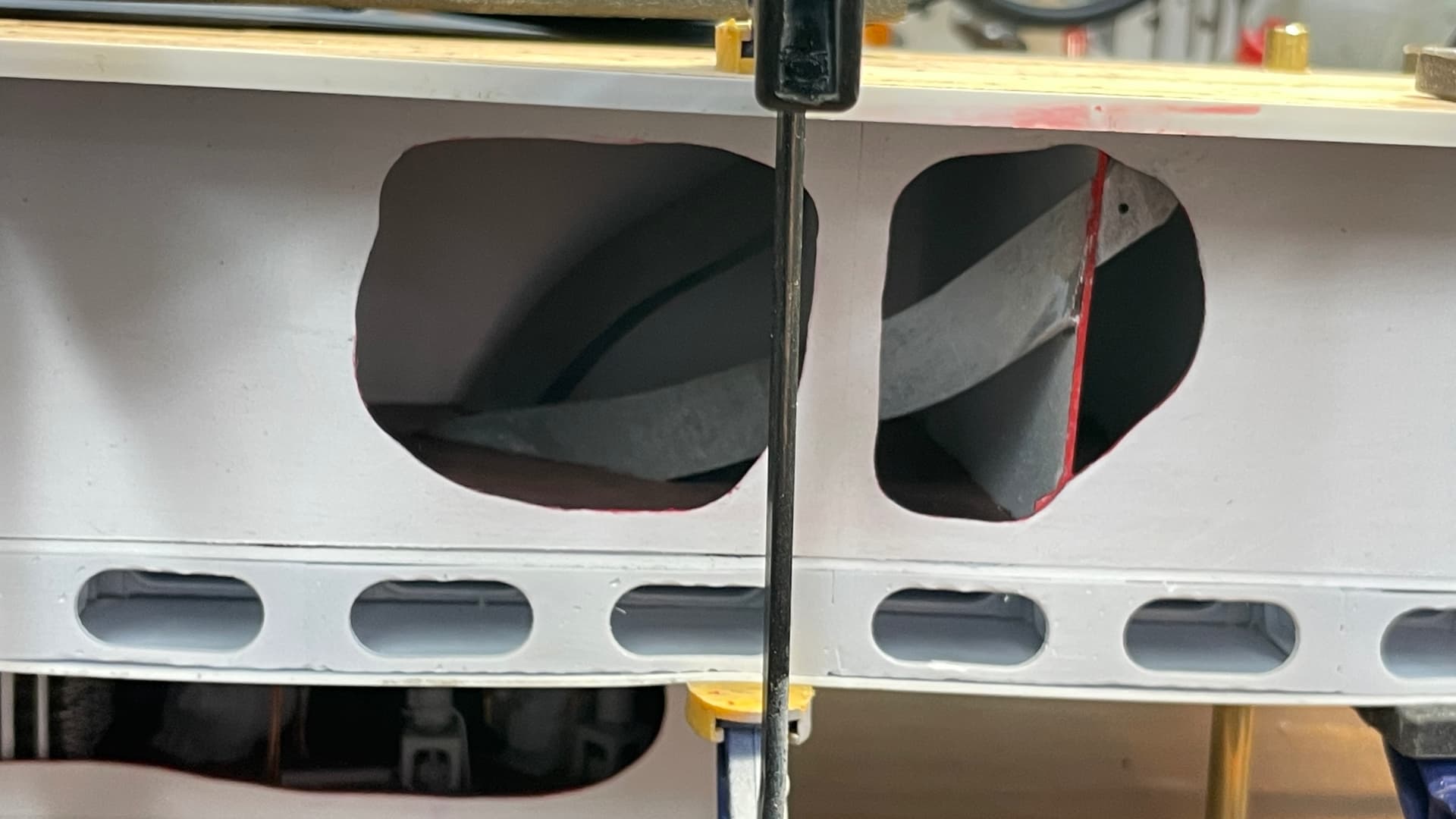
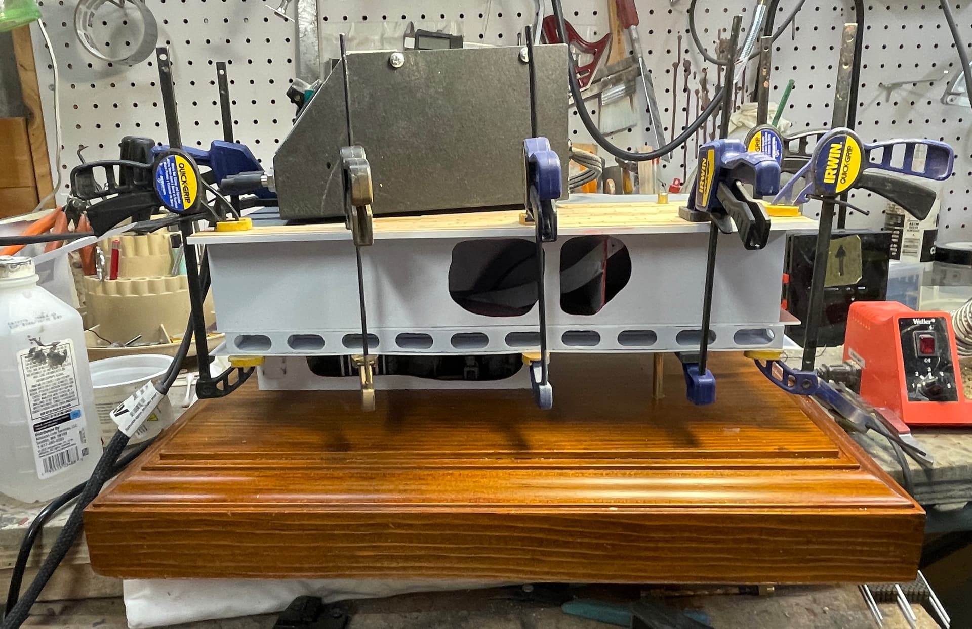
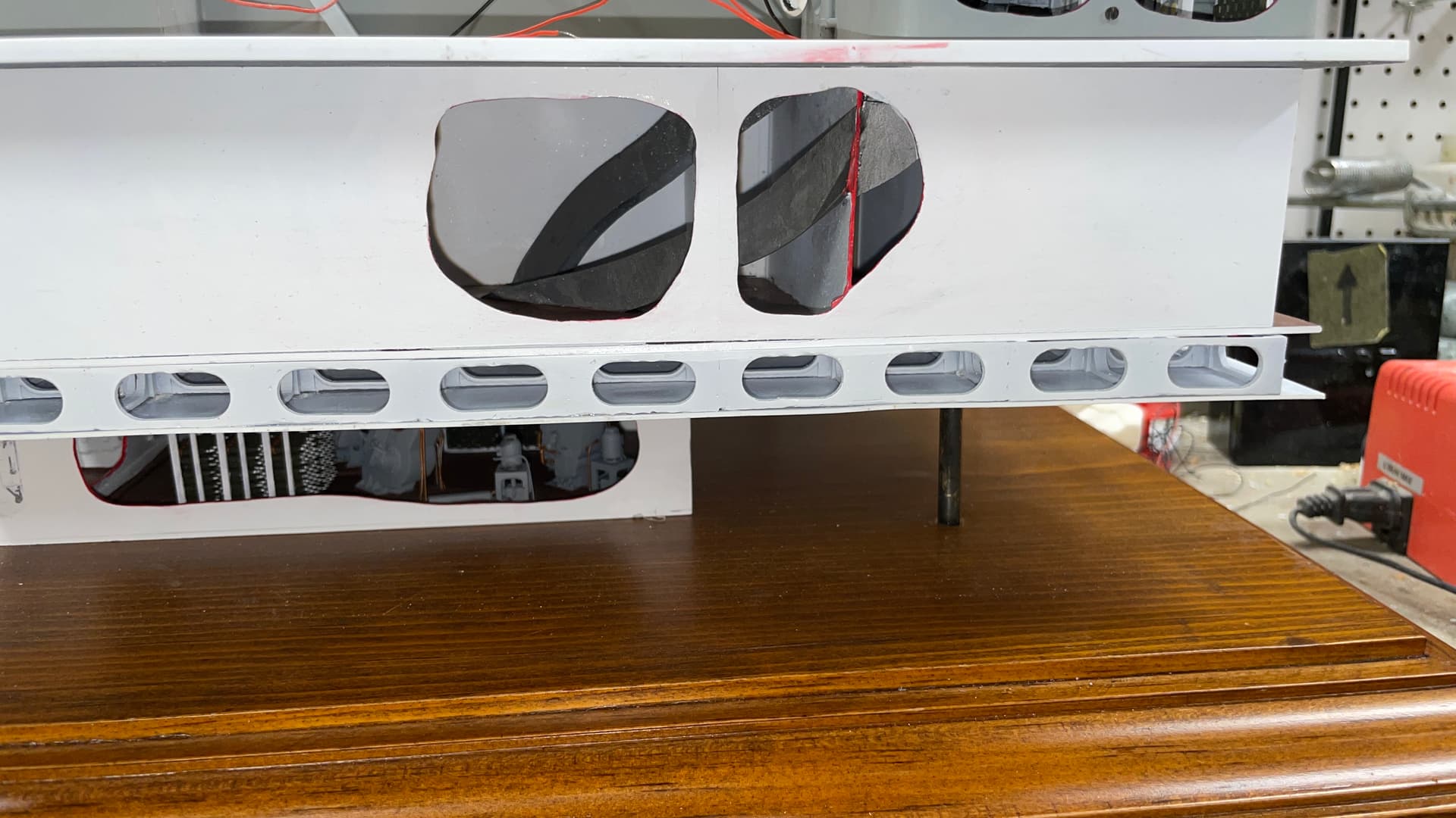
I needed one more day to finish the model, but didn’t do it. I ran into a challenge getting those bits of hoist trunks into the 2nd deck cabin spaces. I was making a mess and had to stop. BUT… we did get that tour and it did not disappoint. My wife, who is anti-military model building and was very luke warm about going on the tour, was blown away. She was quoting Ryan’s comments to others during our Philly visit with friends and family.

The refurbishment project was estimated to cost $10m USD. They were granted $5m from the state of New Jersey, and raised an addtional $4m through donations. While a million short, they started the project. They had a brainstorm to charge for bottom tours. Prices were $1,000//person for Ryan, $500/person for his communications manager and $225 for other docents. It was so successful that to-date they raised another $1.5m and were able to extend the project until mid-June to do some other items that they thought would have to be left undone. Ryan was surprised that they have to beg people to take the $35 in-ship tours, but were booked solid for the $1,000 bottom tours. People are coming from all over the world to see it. Ryan has become somewhat of a celebrity both through the now-100s of videos he produced and getting publicized on CBS World News and the New York Times.

The ship is in the graving dock where it was originally outfitted in 1943. The Big J and Wisconsin were built there. The dry dock is 100 years old and when the Jersey leaves after this project, it’s going to be decommissioned and filled up. It is a casson dock. The wall that keeps out the Delaware River is hollow. It floats. The ship is pushed into position by the tugs, the casson is floated into position and then filled with water. The casson sinks and aligns with the tapered slots on the dock’s sides. When it reaches the bottom, it plugs off the river. The water is pumped out and the ship is sitting on 292, 4’ square concrete blocks with steel shims. At 47,000 tons, each block supports 322,000 pounds.

To accurately position the ship, there are blocks marking the extremes of the ship. They hang a plumb bob from the forepeak and when it’s centered over the block, the ship’s positioned correctly.

To refloat the ship, the water is let into the dock, the casson is pumped out and floated. It’s towed away and the ship is then free to leave.

In order to move the ship under the Walt Whitman Bridge they had to add 500,000 gallons of water (4,000 tons) to lower it deeper in the river to clear the masts. Water was also moved around in the various tanks in the ship to lower it equally on all those 292 blocks. If it contacted one end or the other first, the massive weight would crush that part. It wa a correographed ballet to get it to settle evenly.

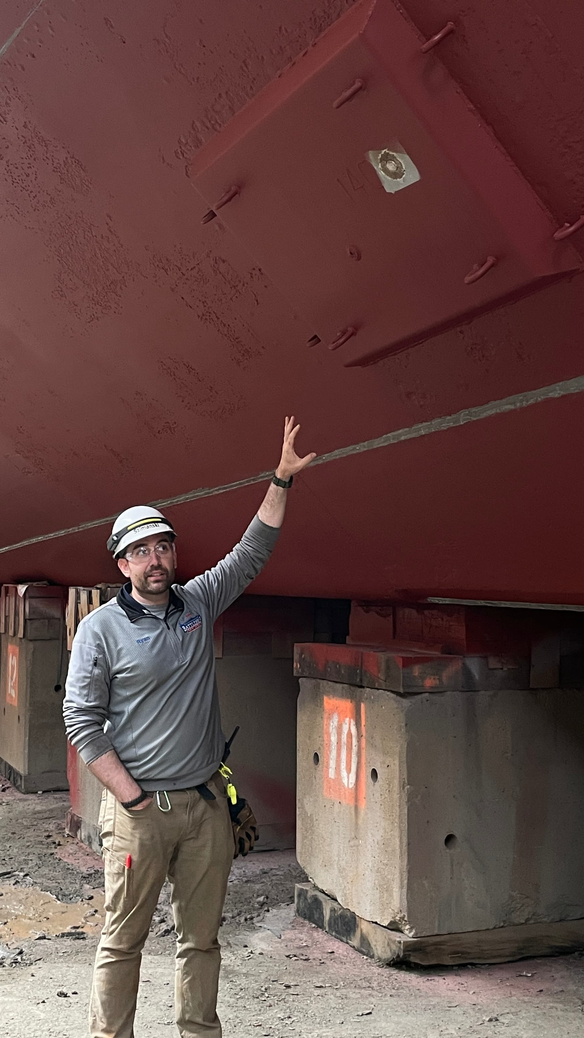
Ryan Syzmanski is not only the curator, but also the project lead on the refurbishment.

This is the first time in 34 years that the ship was out of water. The bottom was in remarkedly good shape.

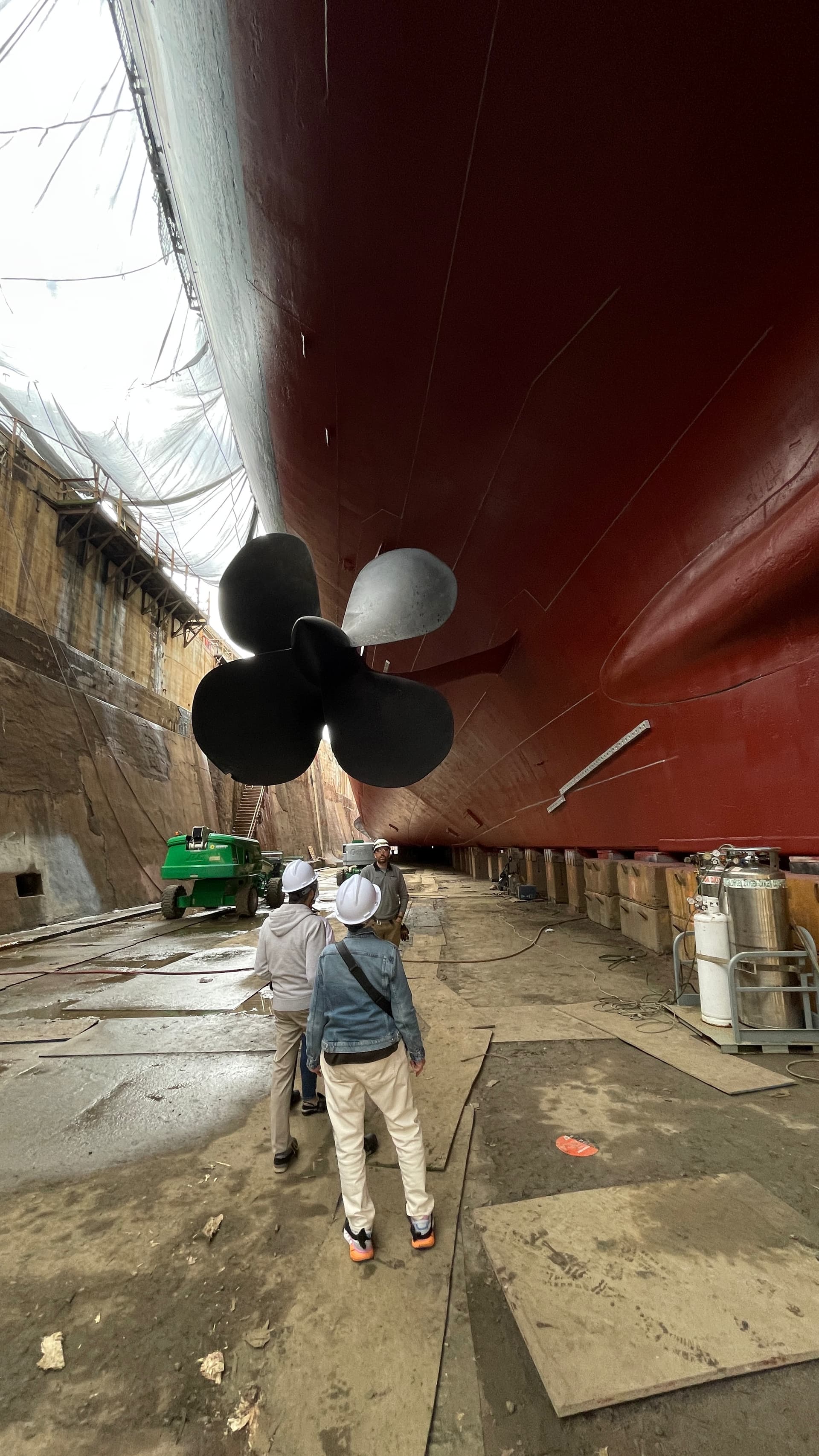
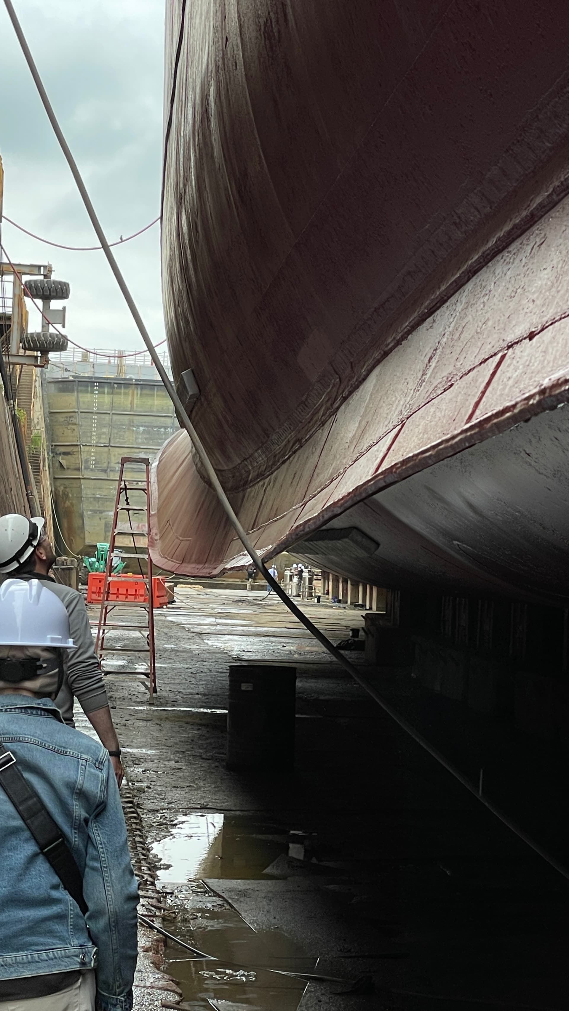
To access the bottom you must negotiate 75 concrete steps from ground level to the bottom. This was daunting to think about, but both my wife and I did it okay. When you descend the steps this is the view. There are stairs at the four corners of the dry dock. You come down at the starboard stern and go back up at the end at the starboard bow.

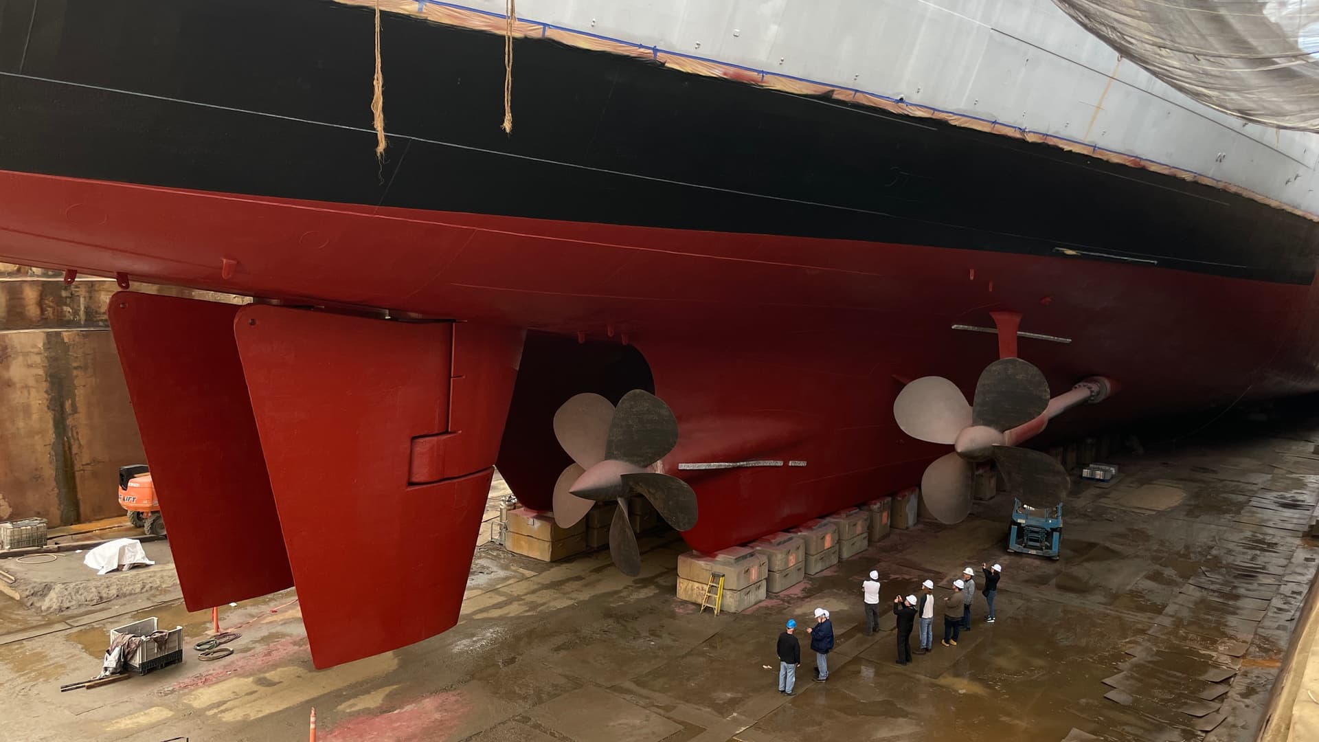
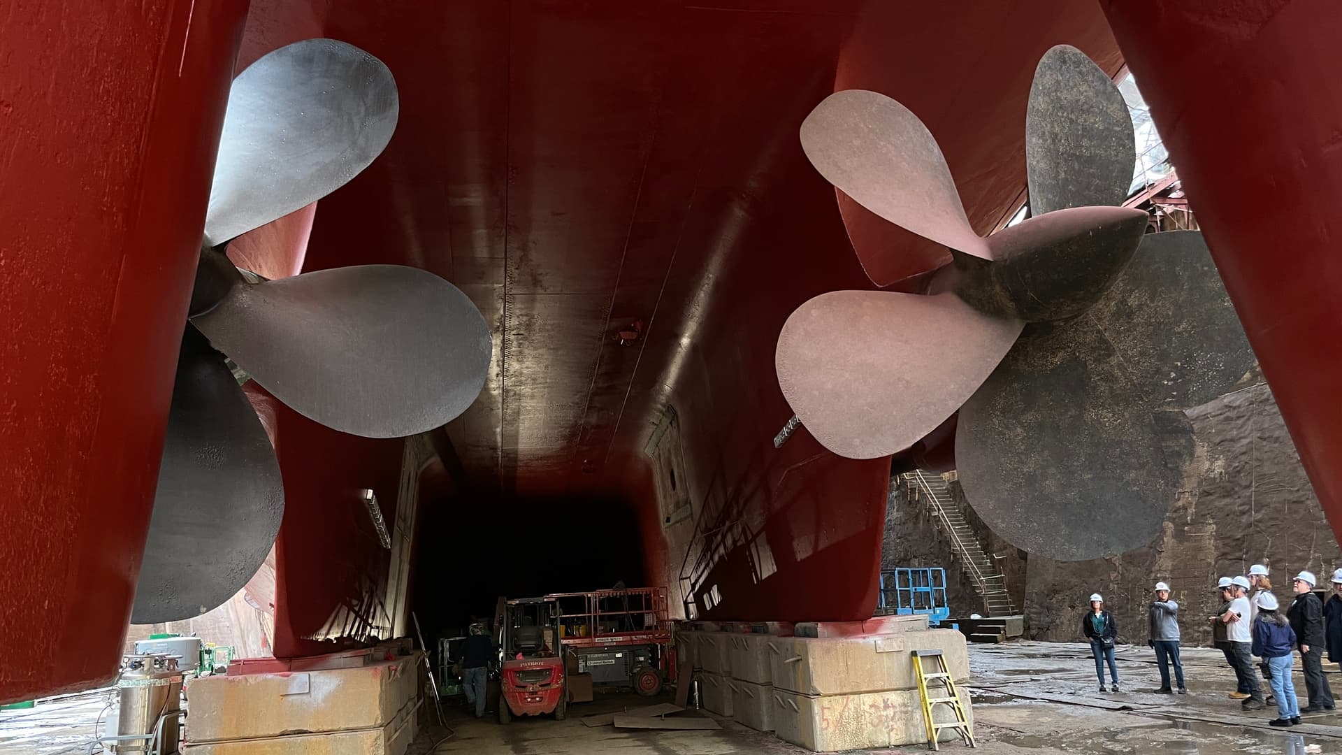
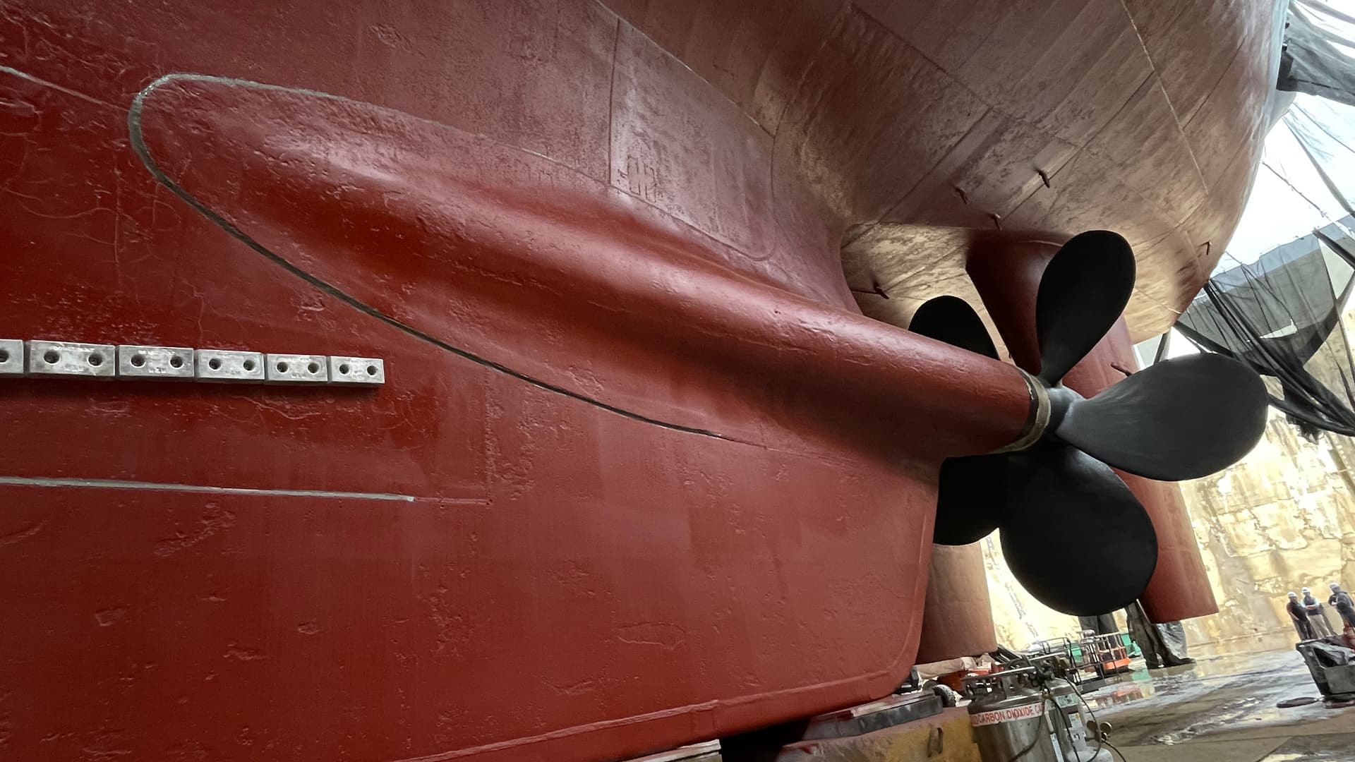
The inboard 5-bladed propellers are 17’ in diameter. The outboard are 4-bladed 18’ in diameter. The two skegs channel water to the inboard props and the rudders to increase their efficiency.

The channel between the skegs is known as “The Holland Tunnel” due to it’s size. Two cars can pass side-by-side. The outer bearing is held in a massive casting that’s welded to the skegs.

The two massive rudders are single piece, hollow castings. They had to do internal inspections of them to determine if any corrosion was taking place. The are of semi-balanced design to reduce the turning force required for their operation. The hull is repainted with 18,000 pounds of special Sherman Williams anti-fouling red.

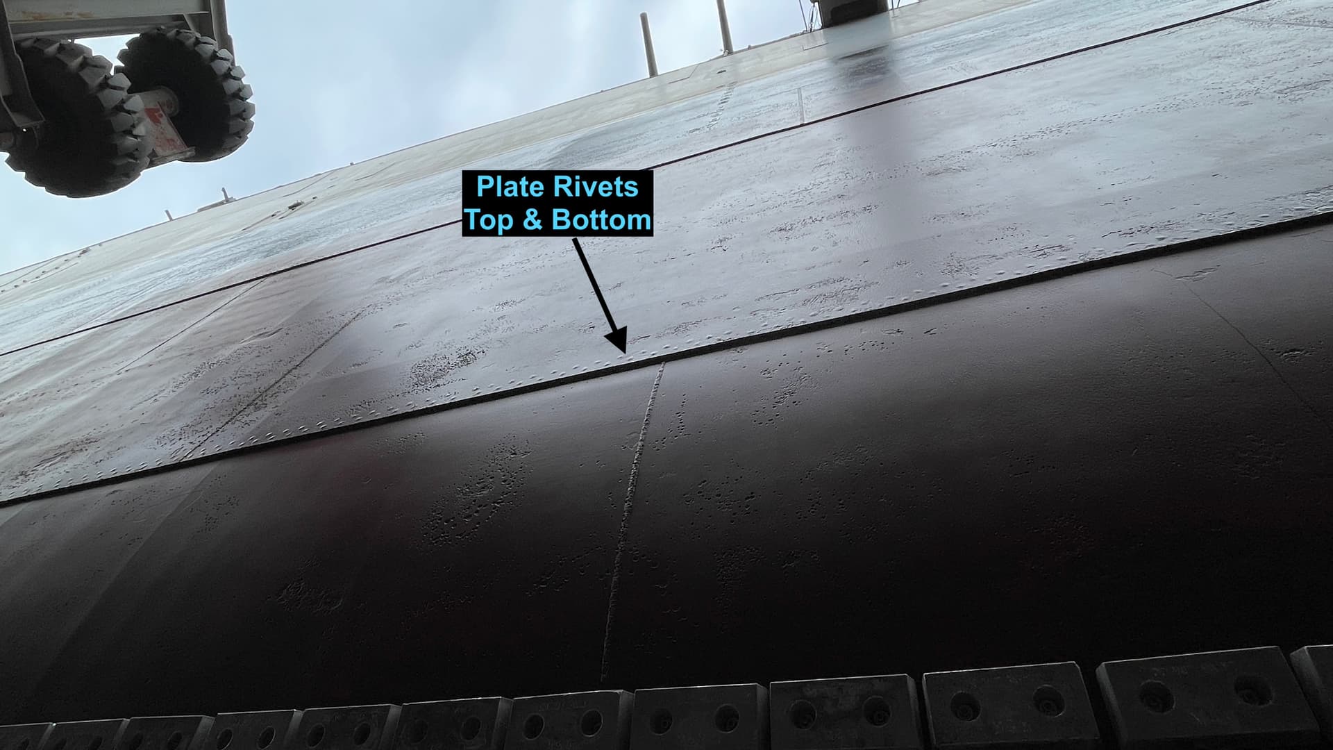
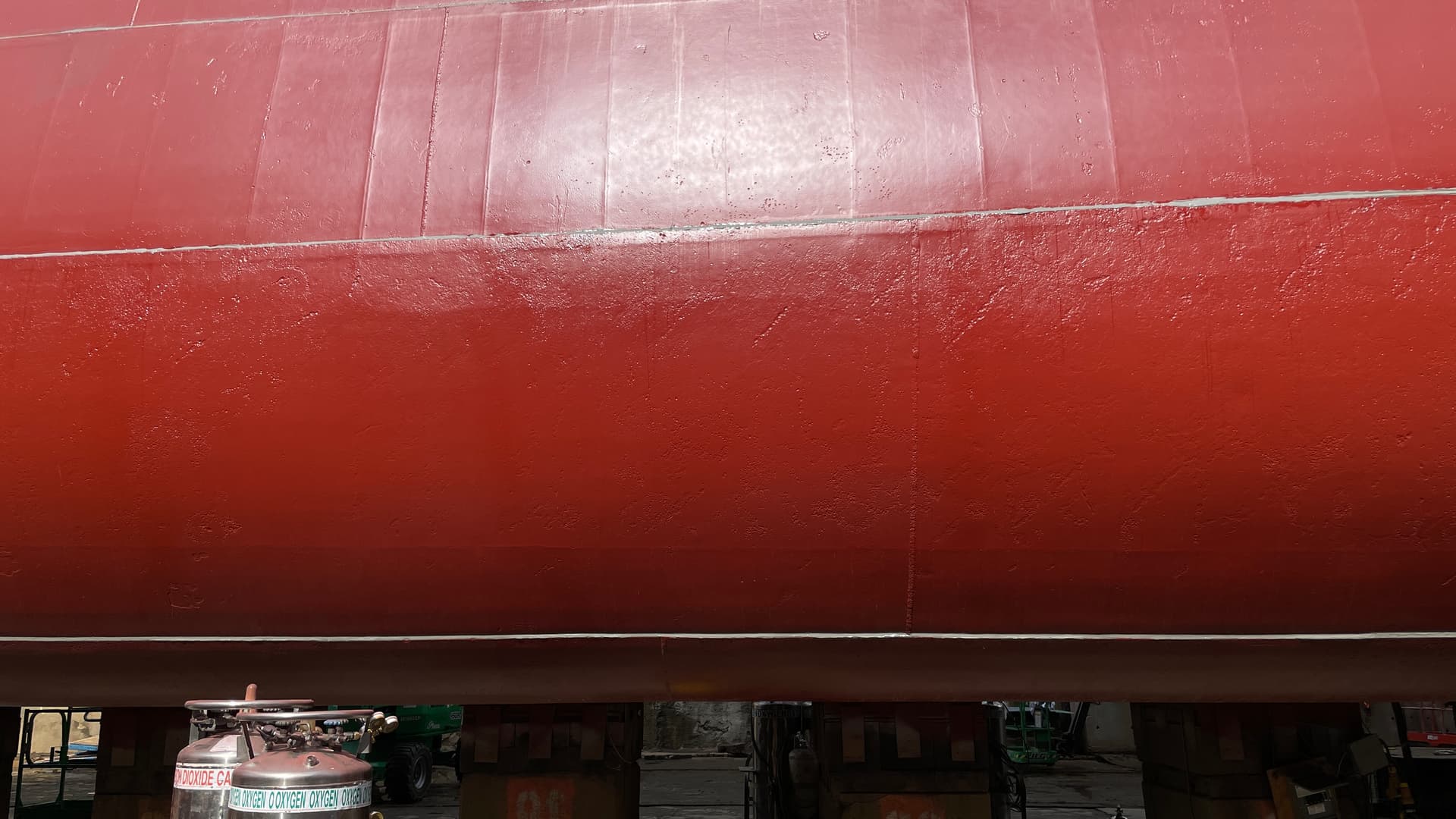
The ship is so huge that it’s impossible to ascertain just how big it is standing below it. I was able to visualize how the hull was constructed. The hull plates are lapped over each going up. The upper and lower edges were rivited with semi-flush rivets and fore and aft joints are welded. Modelers who like to acccentuate the plating on 1:350 scale ship models are overdoing it. The ship’s side are quite smooth.

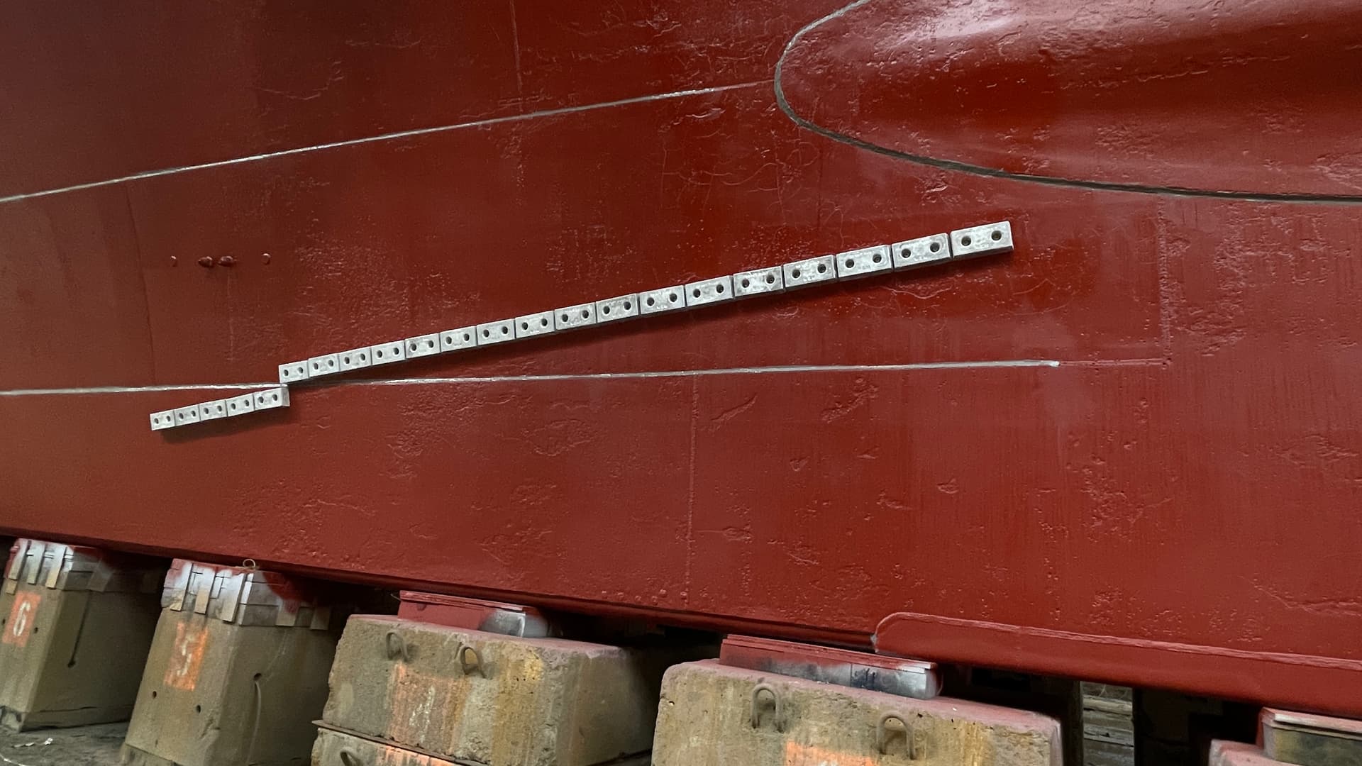
At sea, the ship had 1,600 Zinc galvanic corrosion blocks bolted to the hull to prevent erosion of the properller bronze. The ship’s hull is the negative/ground plane for the vast amount of electrical energy generated within. With the action of saltwater as an electrolyte, the less nobel properllers would give up metal ions to the steel hull. With the zinc, being a less nobel metal than the props, they would be sacrificed saving the properllers.

At least that’s the way it’s supposed to work. Whe the ship’s bottom was exposed, there was no errosion on the zinc blocks. That’s because the ship was not in salt water. It was in brackish water of the lower Delaware River. After analysis, they found that aluminum was the correct metal to use and all 1,600 blocks were replaced. In pure fresh water the metal would be magnesium.

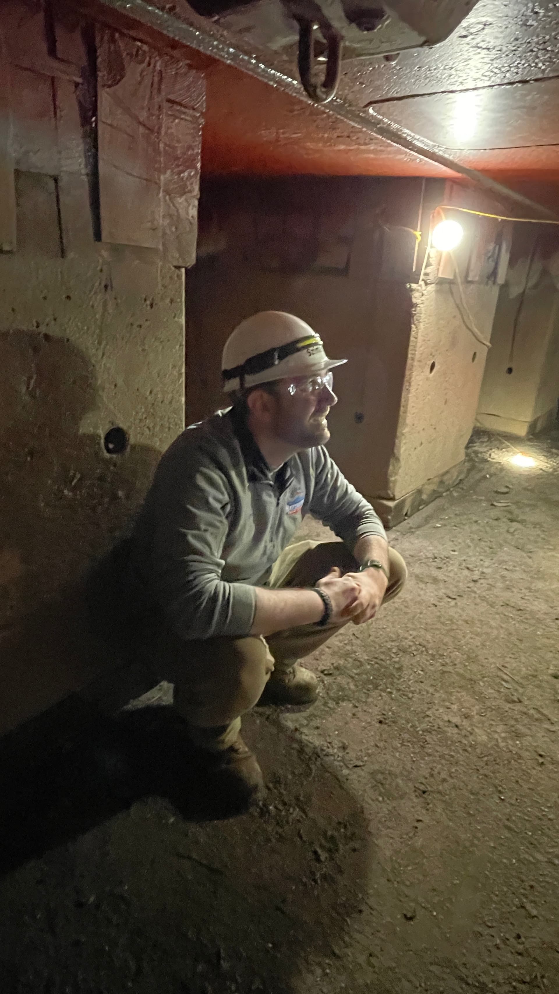
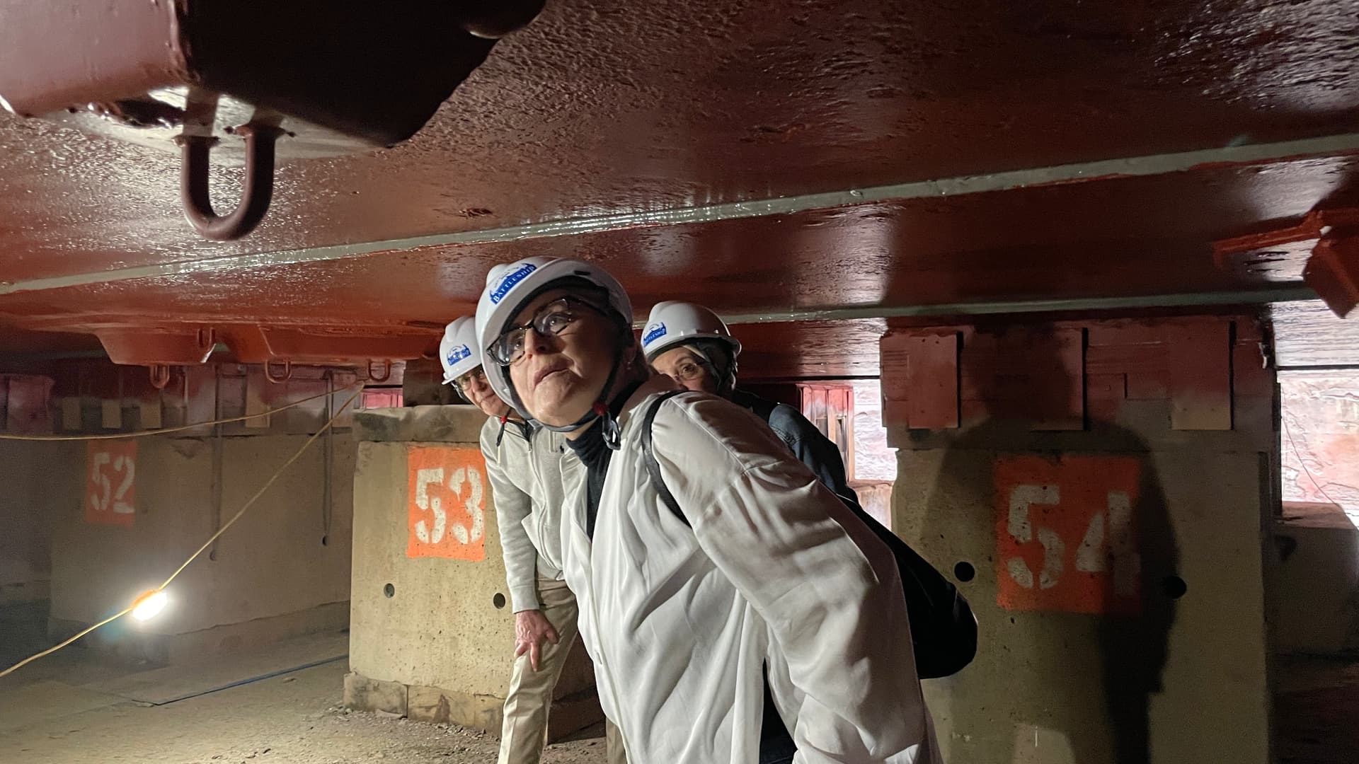
Clearance under the ship is tight and somewhat claustrophobic at four feet. This height was chosen supposedly so the painter’s can sit on a paint bucket while painting the vast bottom. Here was Ryan regaling us on that thought.

We were given hard harts which came in very, very handy when stooping under the vessel.

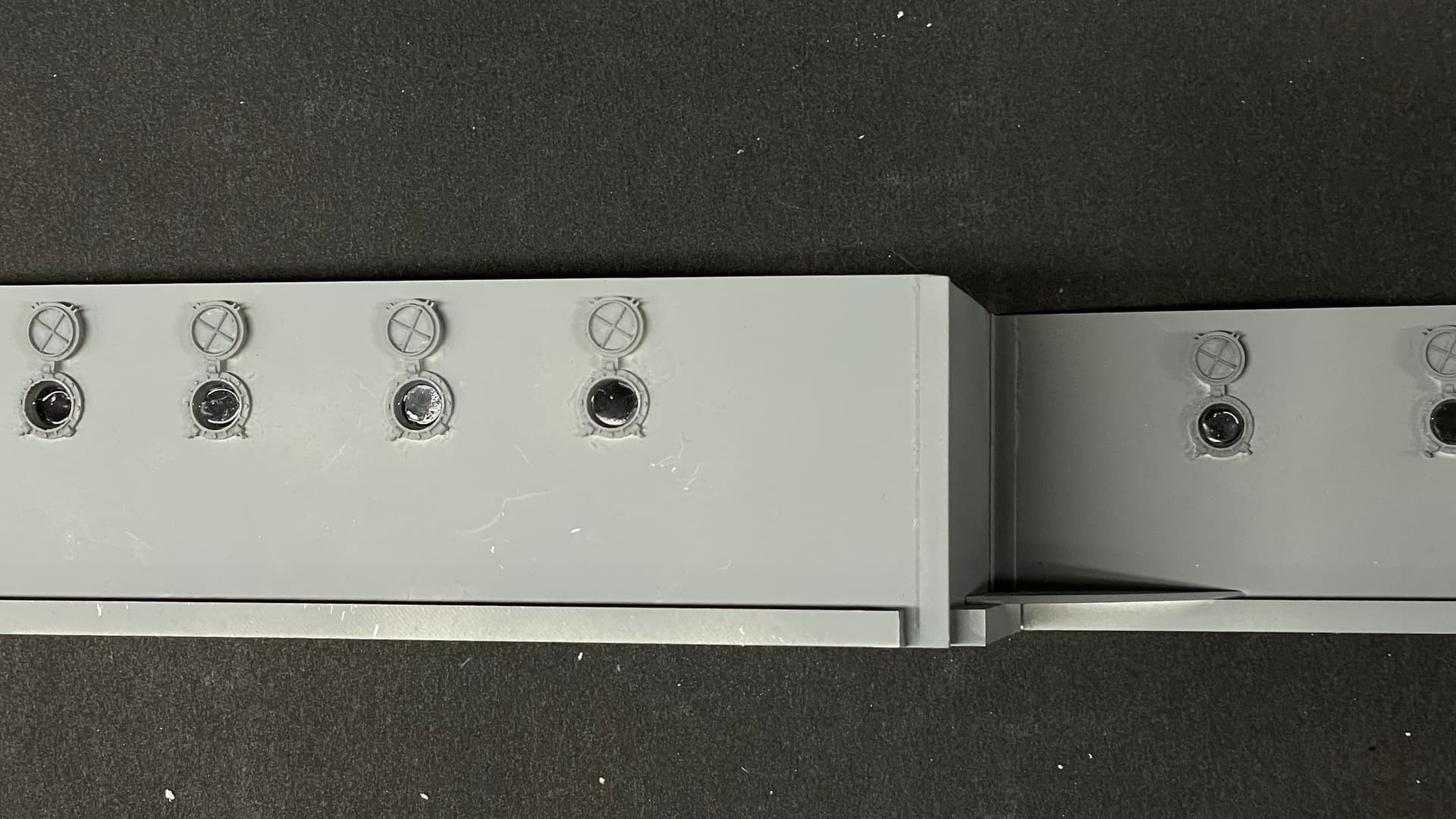
The ship has 160 sea chests, openings to pass water into and out of the ship for all the various things needing it, e.g., boiler feed, condenser cooling water, drinking water feed to the evaporators, etc. All of these are plugged with welded covers and all had to be inspected for leakage. At sea they would all be open. They penetrate the hull at various angles depending on if the ship’s forward velocity is used to give a ram effect. The Delaware River’s visiblility is about 15" so nothing could be learned while it was in the water. The assessment had to wait until the ship was exposed.

The bilge keel was damaged during some move or another and was fixed by adding welded sheet steel. The welding popped the rivet next to the damage requiring it to be welded, which popped the next rivet and so it went for hundreds of them.

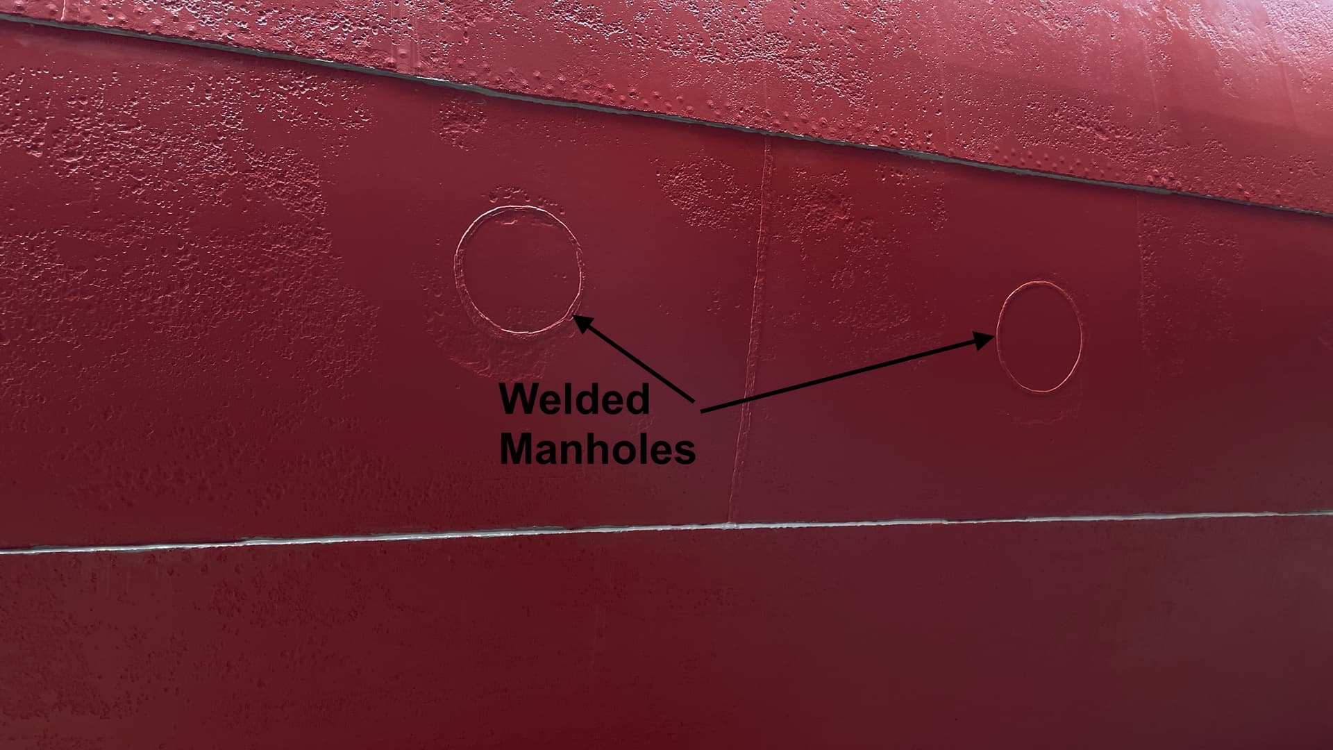
Another thing found when the ship was dry were these welded circles that were close to the bilge turn. They didn’t know what they were for. After investigating, it was determined that during the 1980s refit, the ship was converted from Bunker C oil to distillate (heating oil). Before refilling the tanks, they had to be completely cleaned of all the tarry residue from the heavy oil. The fuel tanks form are the entire bottom of the first layer of the triple-bottomed hull. They cut man-sized holes in the tanks and men with steam lances had to enter to melt and then remove the tar. It was an awful task! They then welded the circles back on. Having fuel at the bottom provided buoyancy control and torpedo defense.

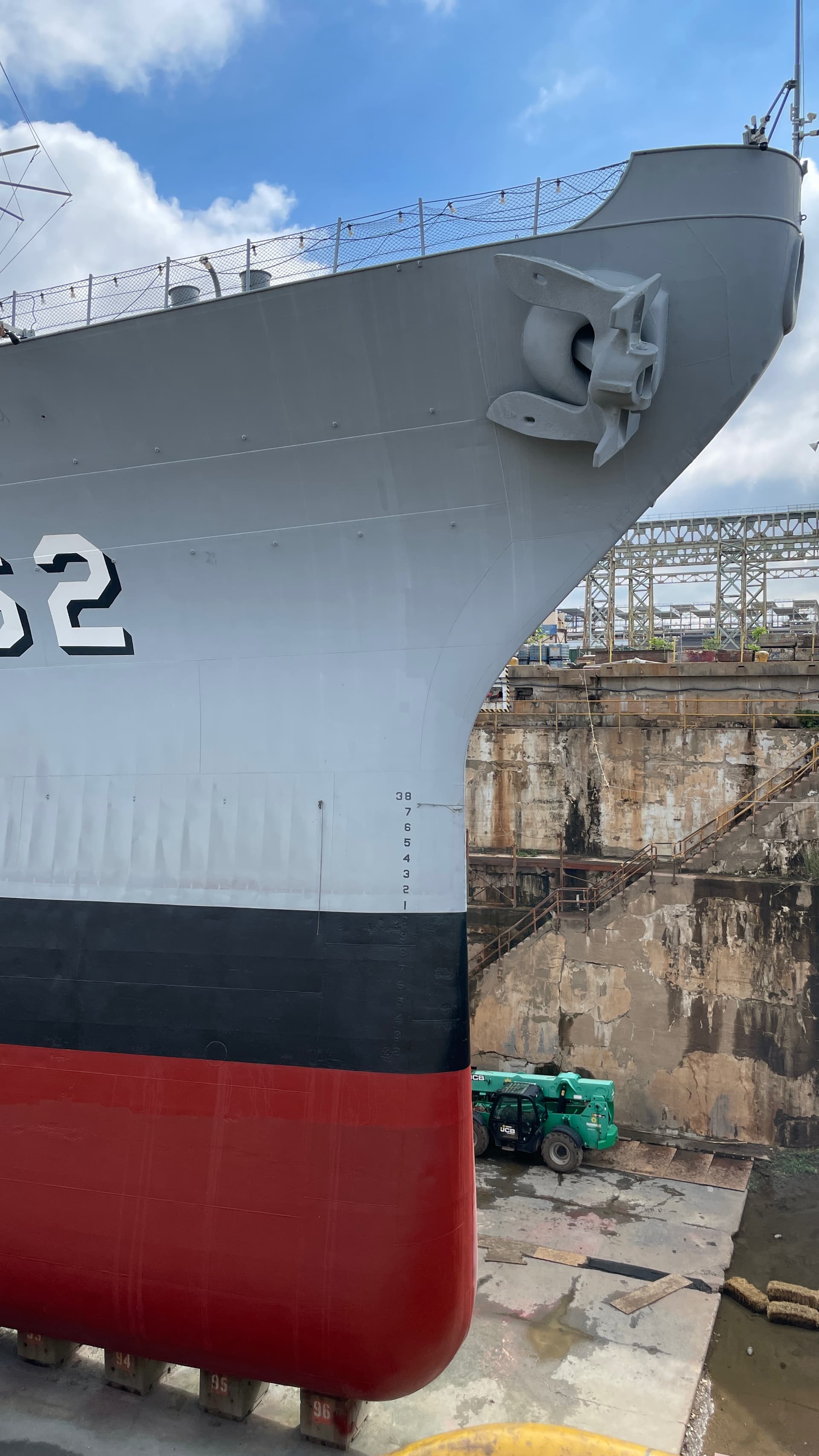
Most of the hull skin is very streamlined with minimum ripples. There is some erosion that’s visible under the fresh coat of paint, but all in all the ship looks fabulous for being 81 years old.

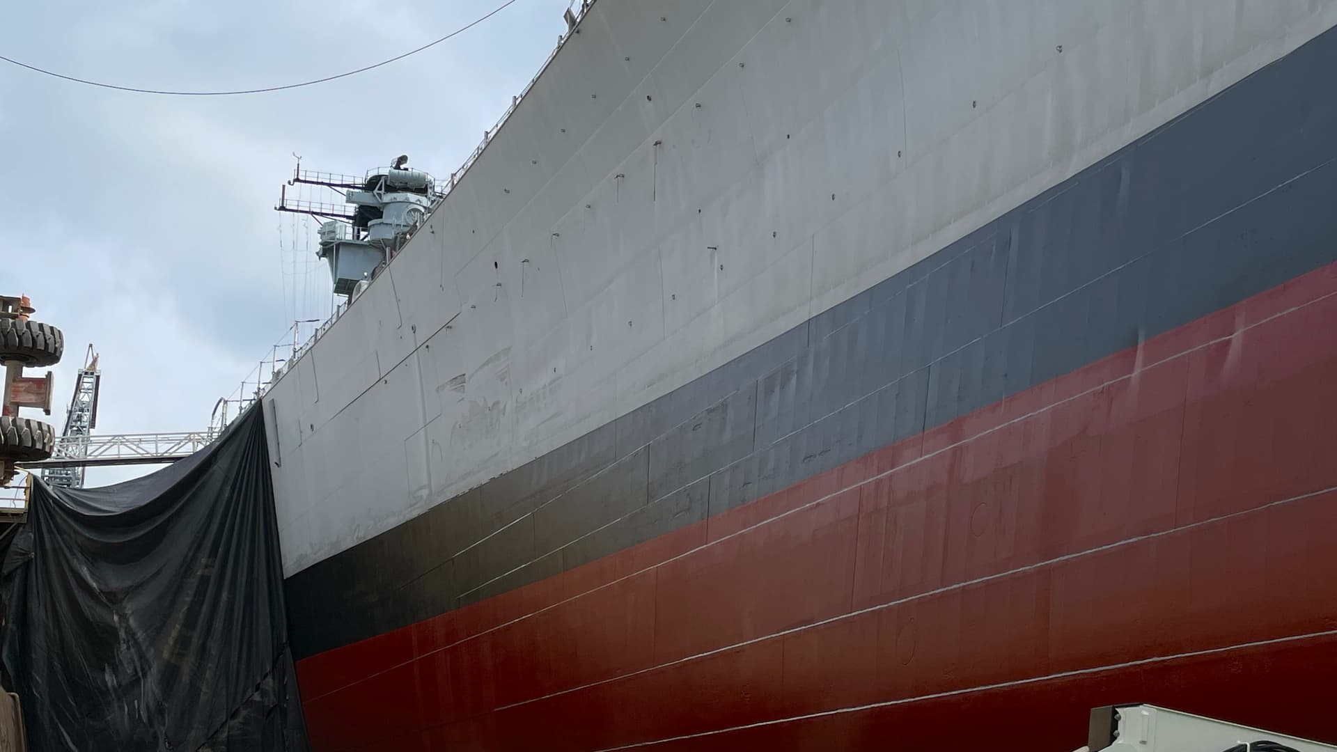
There’s a minimum amount of ‘oil-canning’ around the areas with the lightest plating, namely the bow and stern. It’s most pronounced on the black boot topping. The sun’s heat expands the steel, but it’s constrained by the framing. The only place the thin steel can go is to buckle slightly. Modelers who want to add this detail need to consider it’s only at certain areas of the hull, not the whole ship.

Where the ship is sitting on the blocks it can’t be painted. To accomodate this when on active duty, the ship is drydocked every two years for a bottom paint. It’s positioned in three ways. The 2nd and 3rd positions are two and four feet off the original position, so they can paint the area that was blocked initially. However, from WW2 to the last deploy, the ship was only activated for a year at a time, and each time they painted it, they used position 1, meaning there were 292, 4ft square areas on the bottom that hadn’t been painted in 75 years. To fix this problem, the ship will be re-floated and moved 4ft forward and set back on the blocks in the new position exposing the unpainted areas. This little move will cost over $100,000.00.

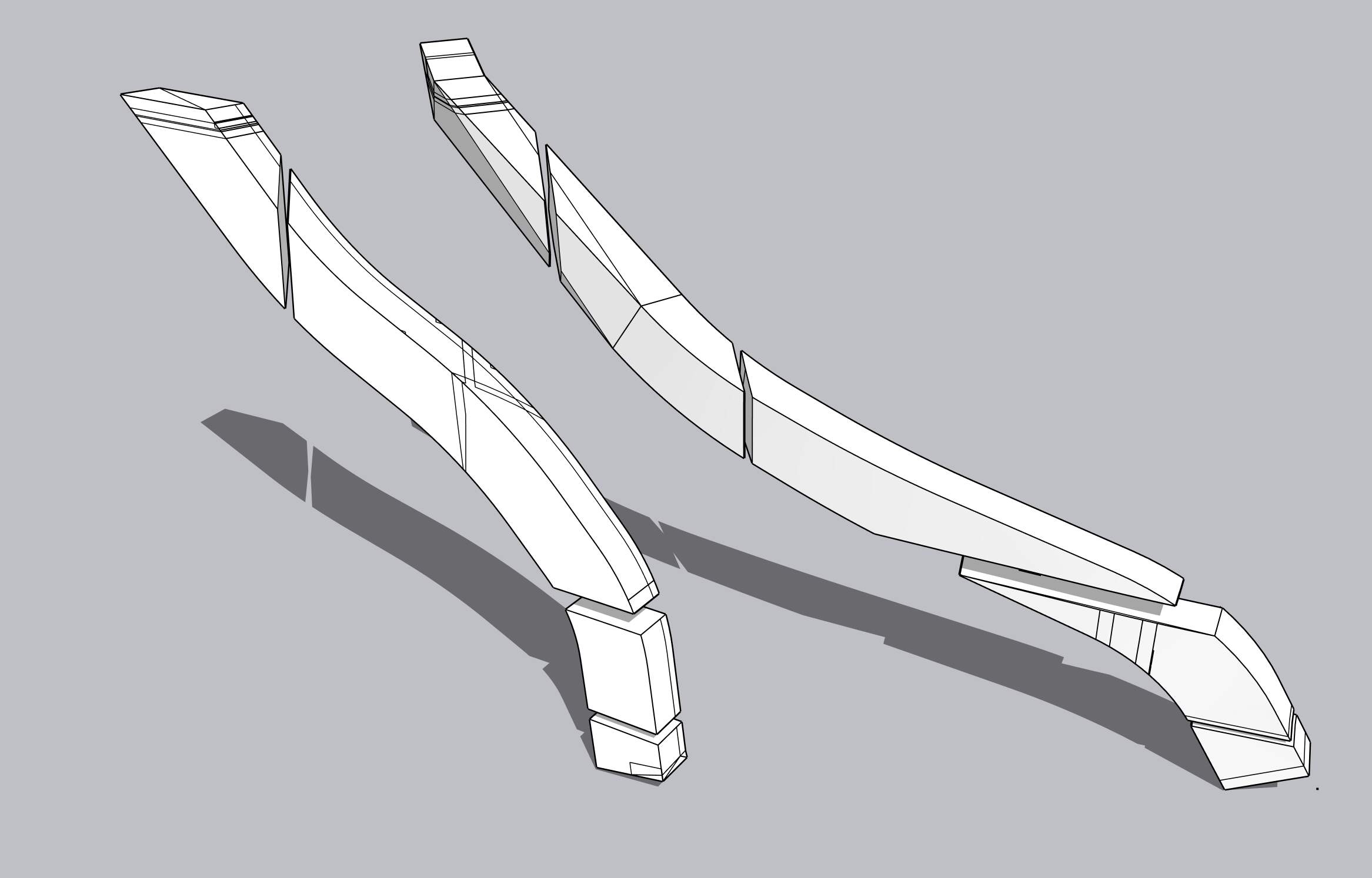
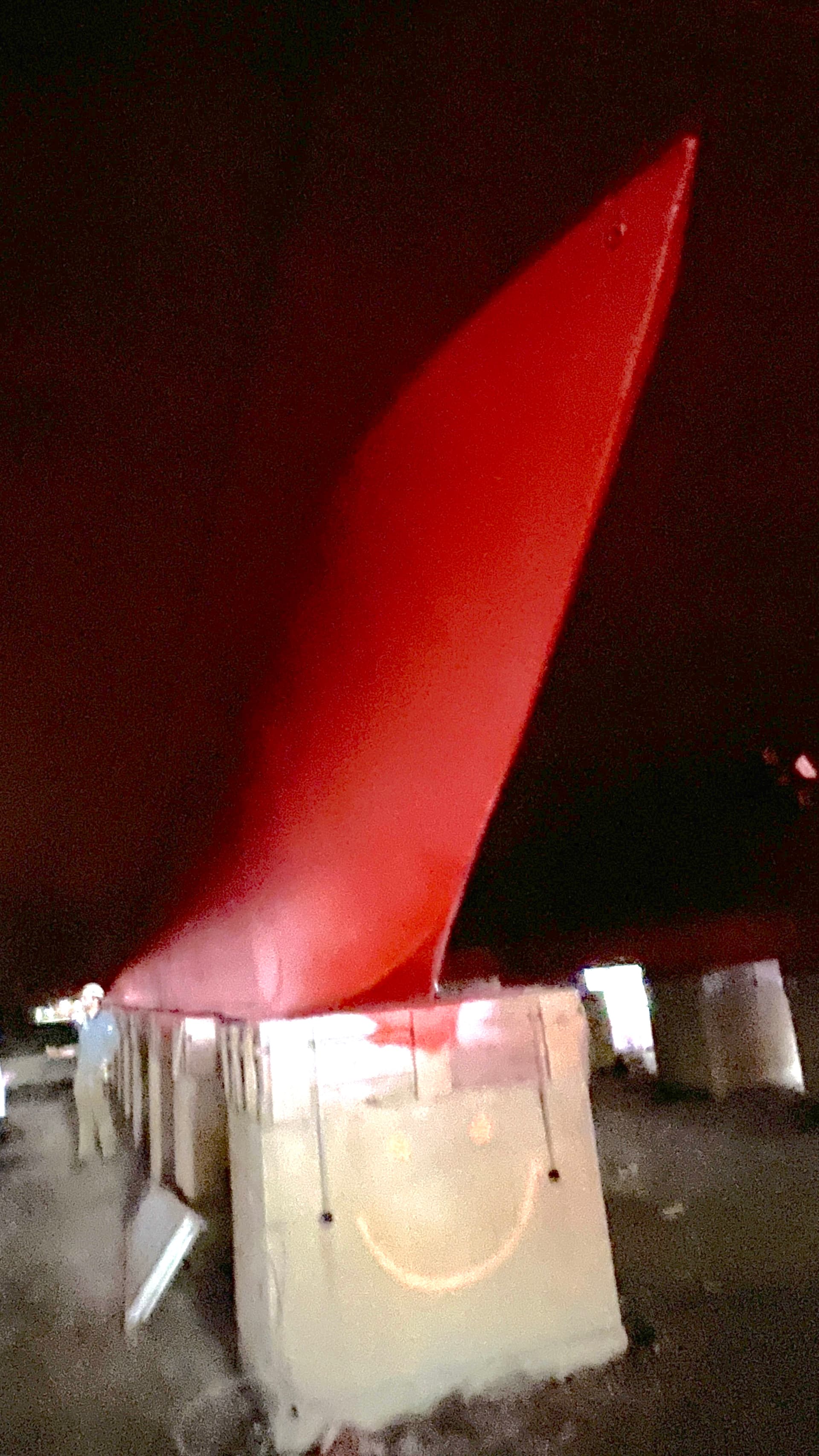
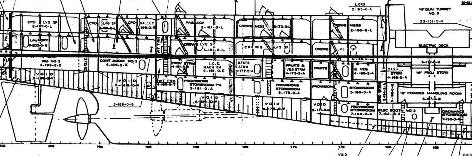
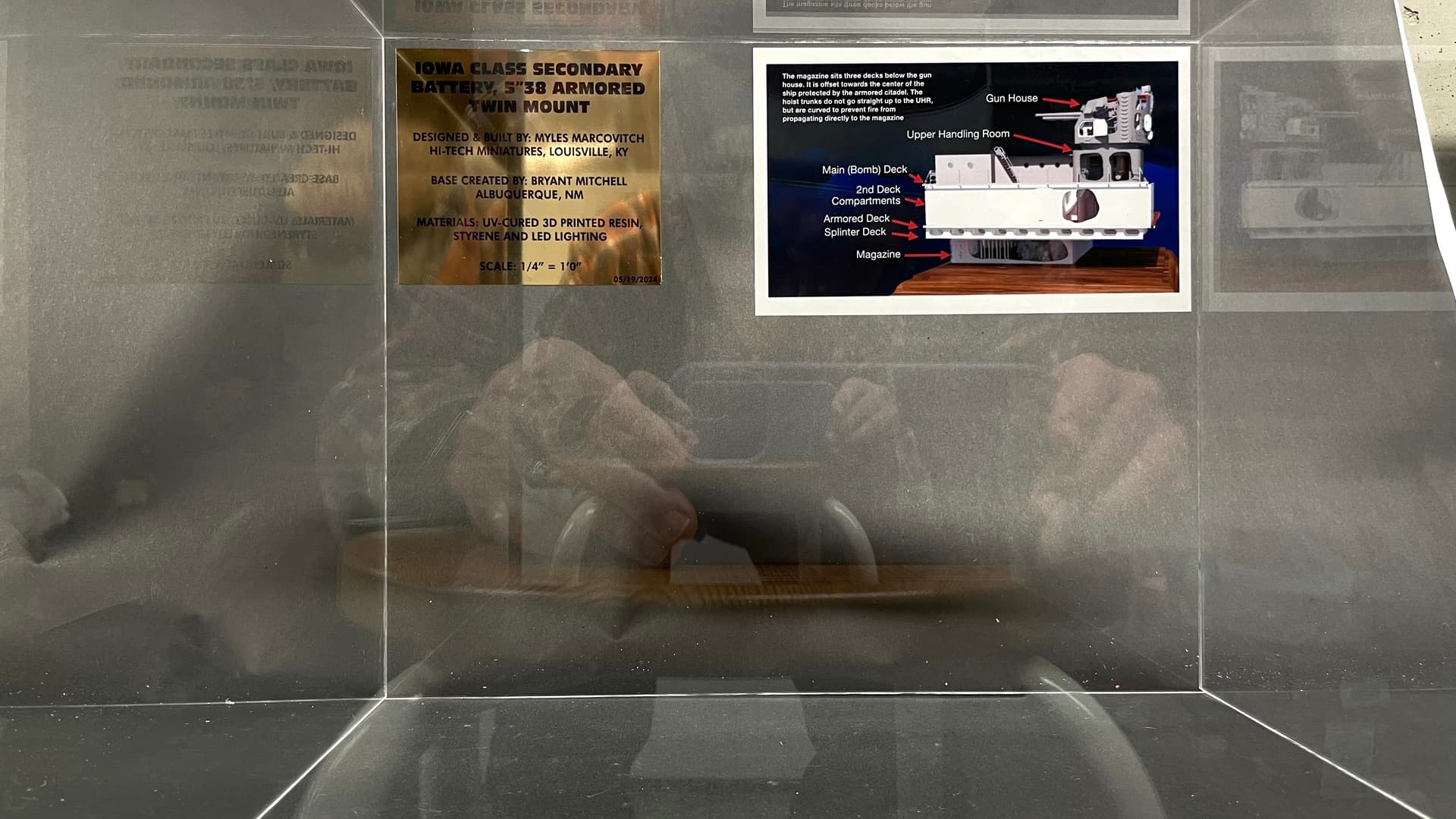
There is one detail that is never included on models of the Iowas. Between the skegs is the tail of the actual keel of the ship. It’s rather pronounced and ends in a very sharp knife edge, mirroring that of the bow. It’s buried in the Holland Tunnel and when you see side elevations, they don’t show it. Even mid-line section drawings don’t show it and NO MODELs have it, but there it is.

It is not shown on this section drawing.

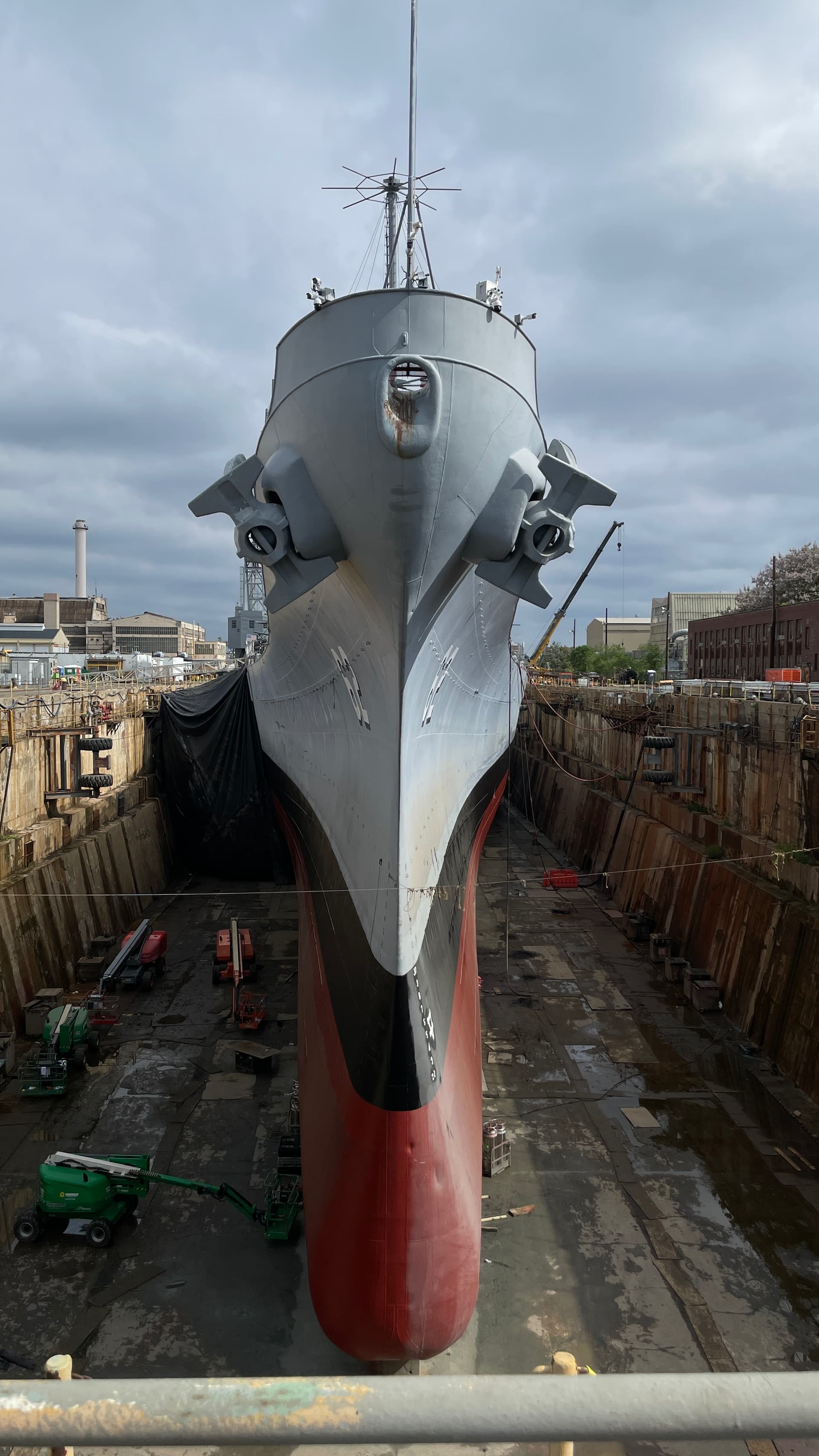
When we got up those steps we walked out on the catwalk atop the casson and I took this shot straight onto the bow. From this view the ship is all about speed.

From the stern the ship is all power; 212,000 hp to move 57,000 tons at 35 knots in sea trials.

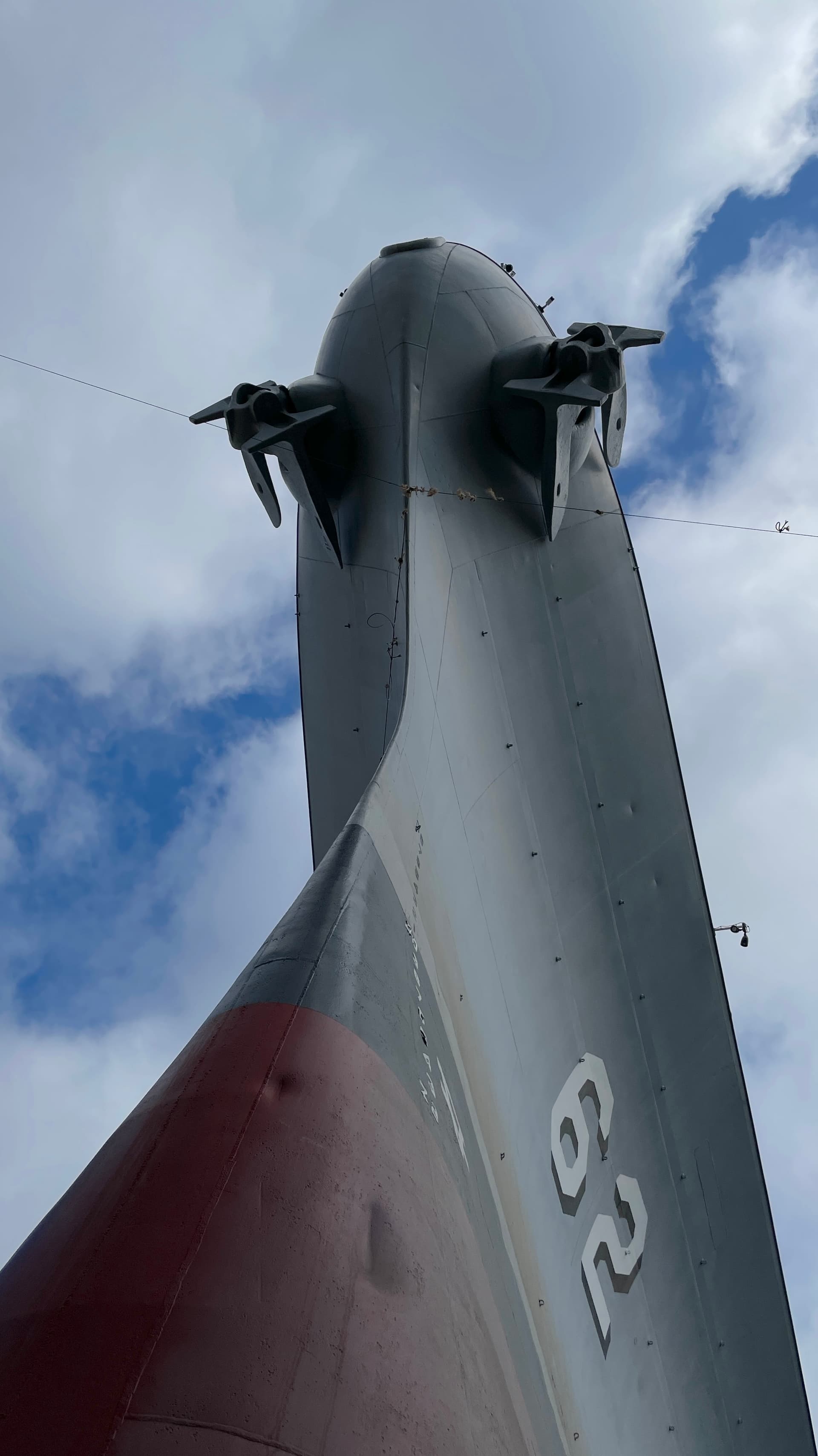
Looking up at the bow you realize how tall the hull is. Due to it’s massive displacement and fine lines, the ship draws 36 feet of water.

The bow’s profile is gorgeous!

The first two Iowas (Iowa and NJ) didn’t sit with the main deck parallel to the ocean surface. The bow was 8 feet higher than the stern and the water line refected this. The last two; Missouri and Wisconsin, had 5,000 tons of armor added to turret #1’s barbette and these two ships sit level. If you’re modeling the NJ you should consider this difference.

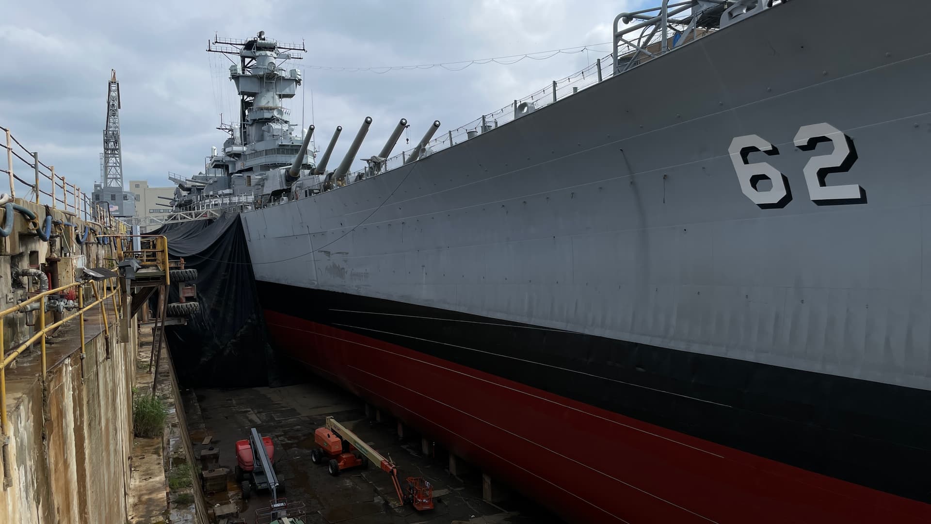
Here’s a look down the length from the casson.

Without 10,000 tons of ammo, fuel and stores, the ship’s waterline is 8 feet lower than it would be in active duty.

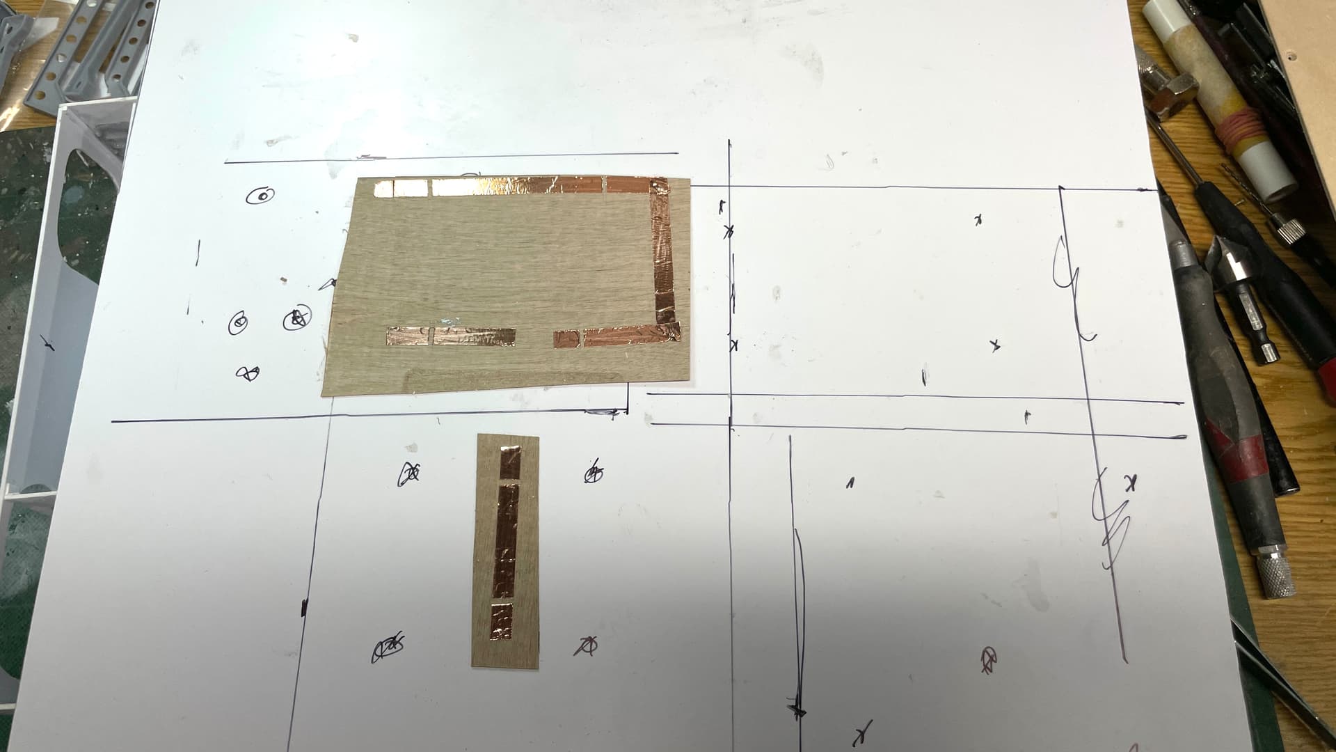
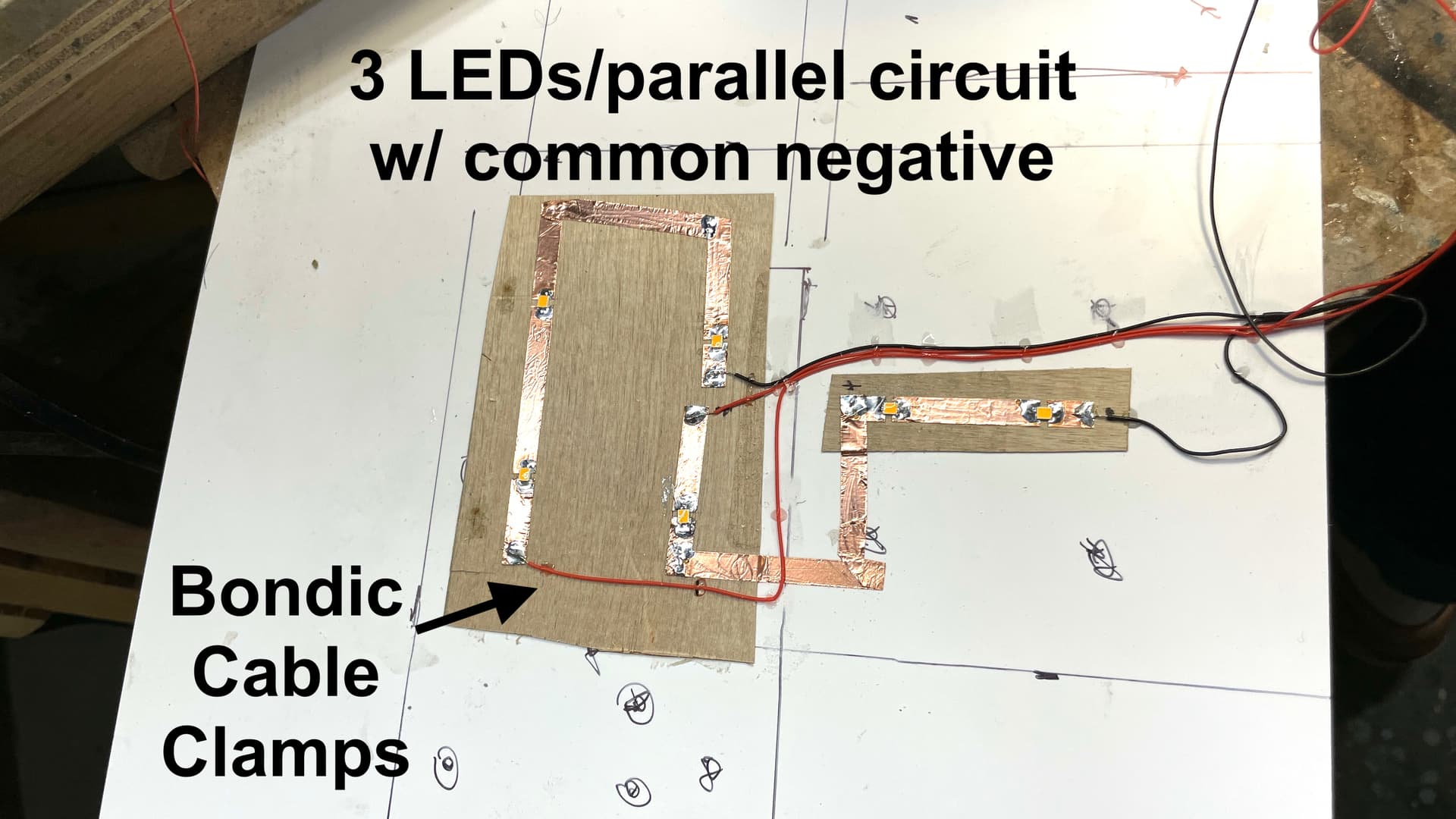
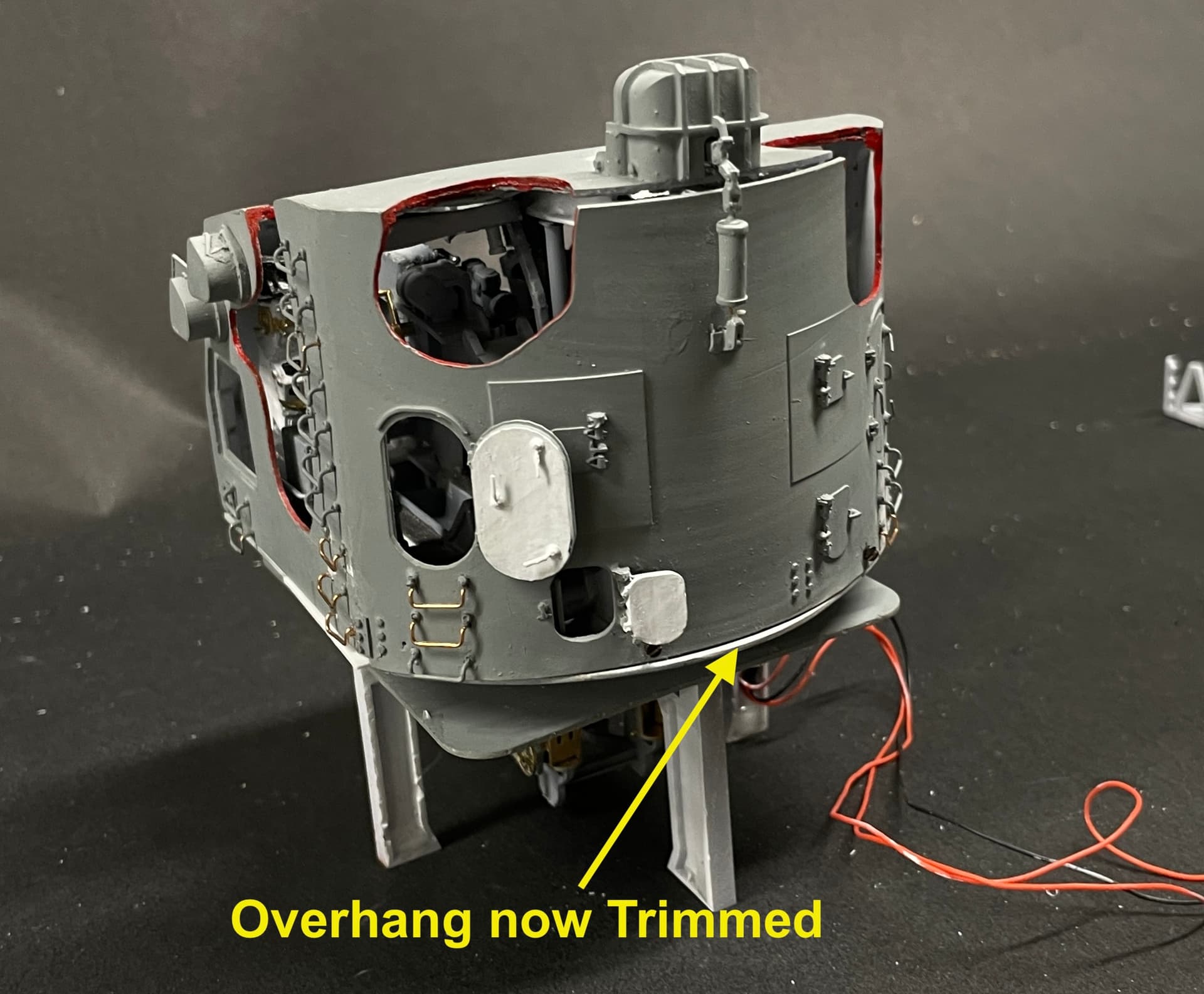
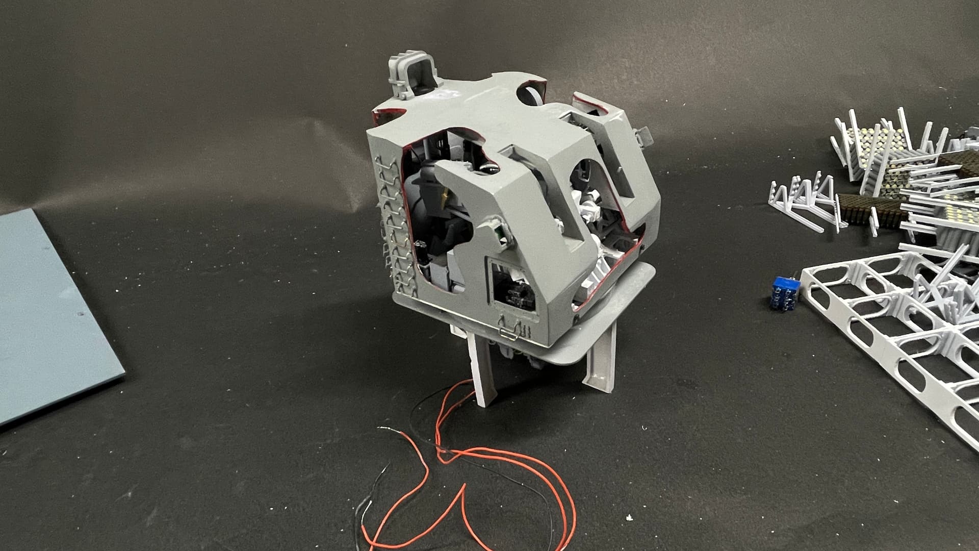
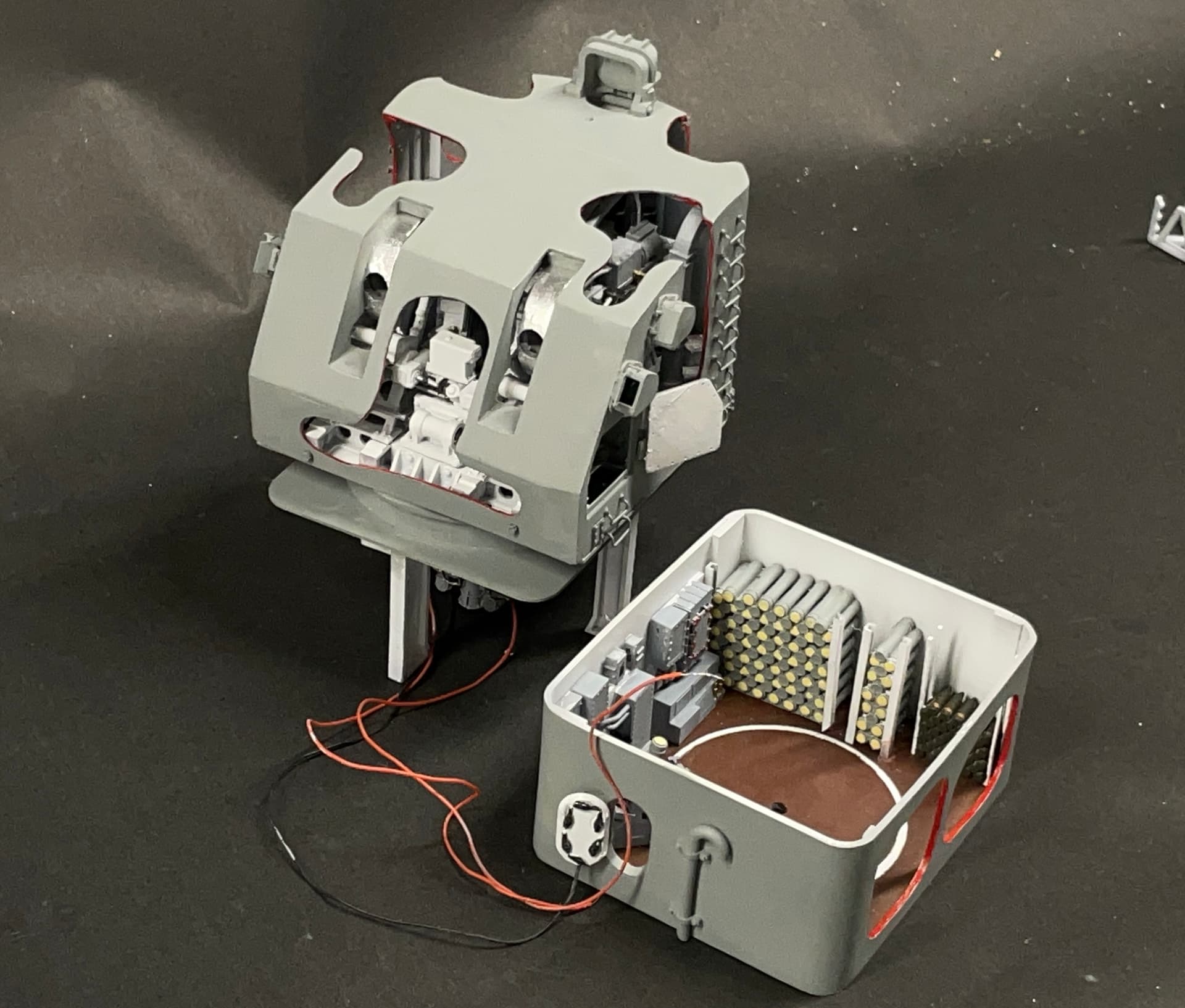
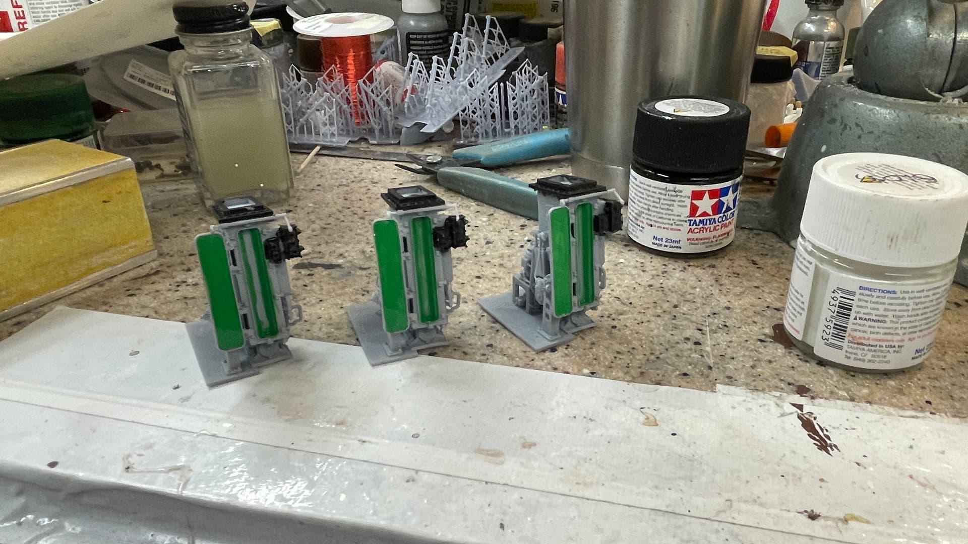
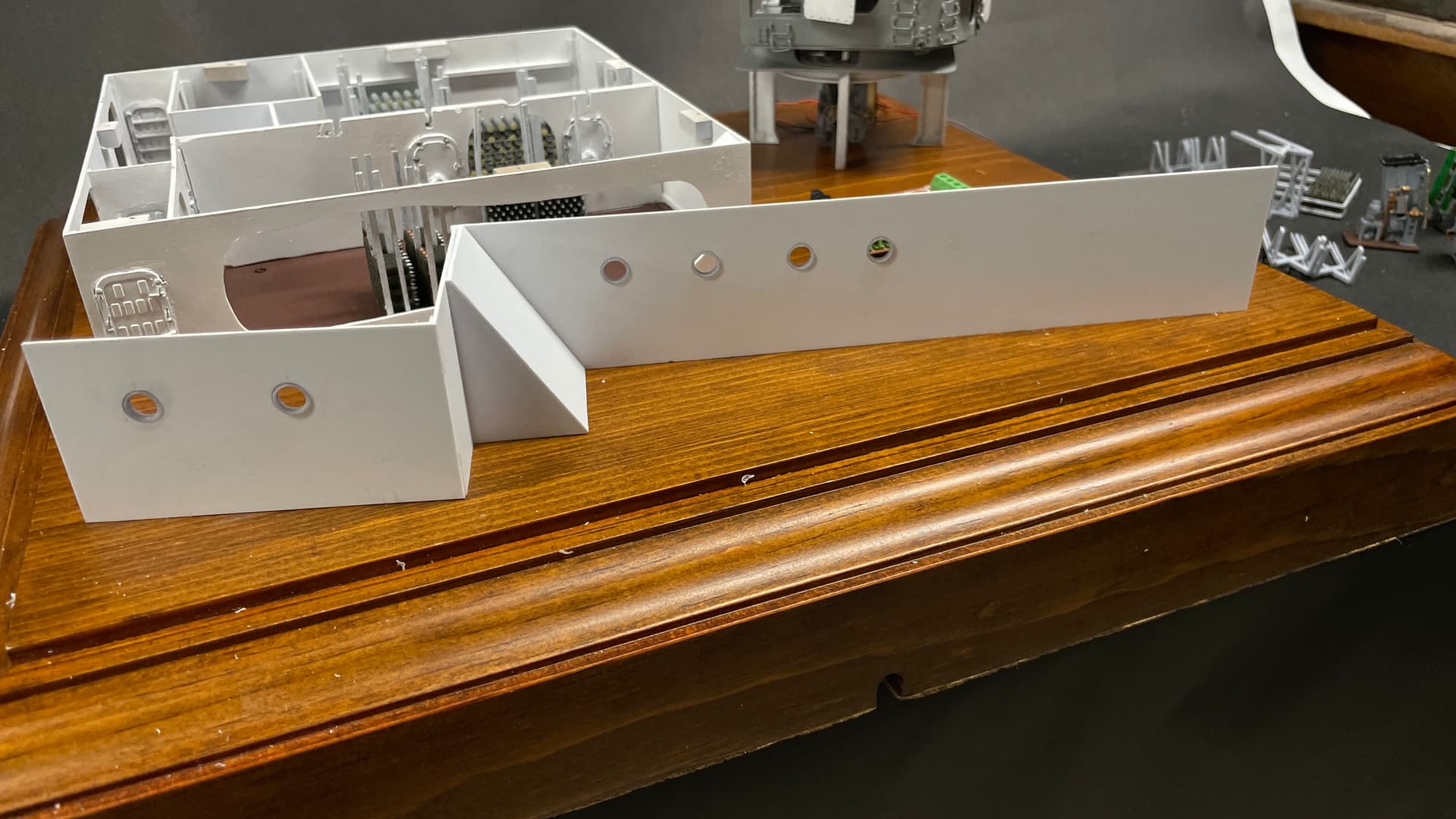
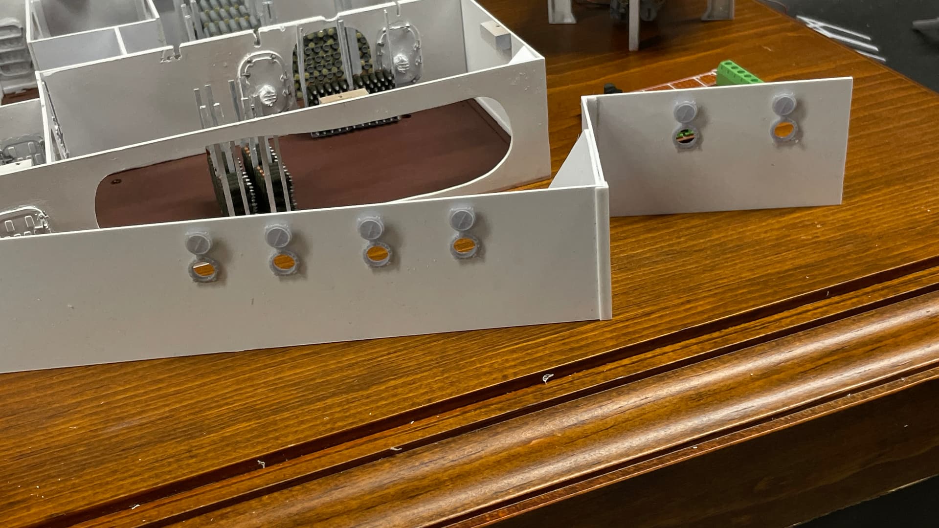
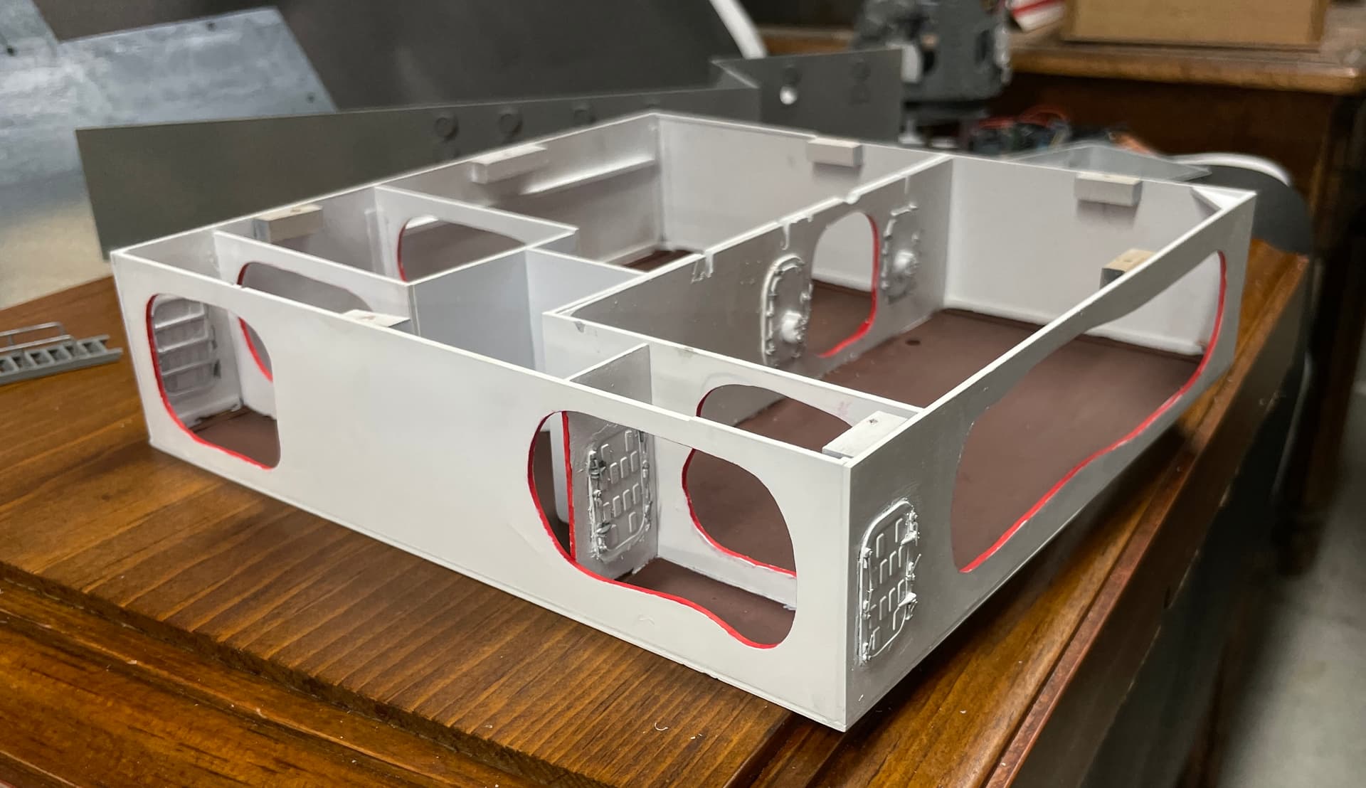
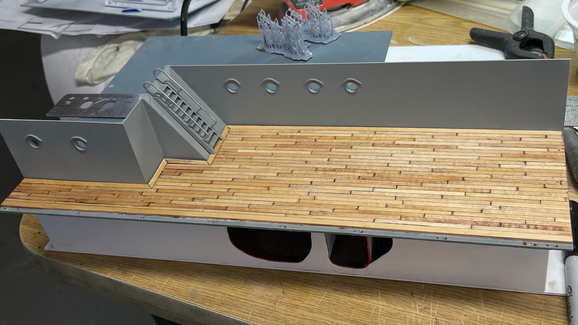
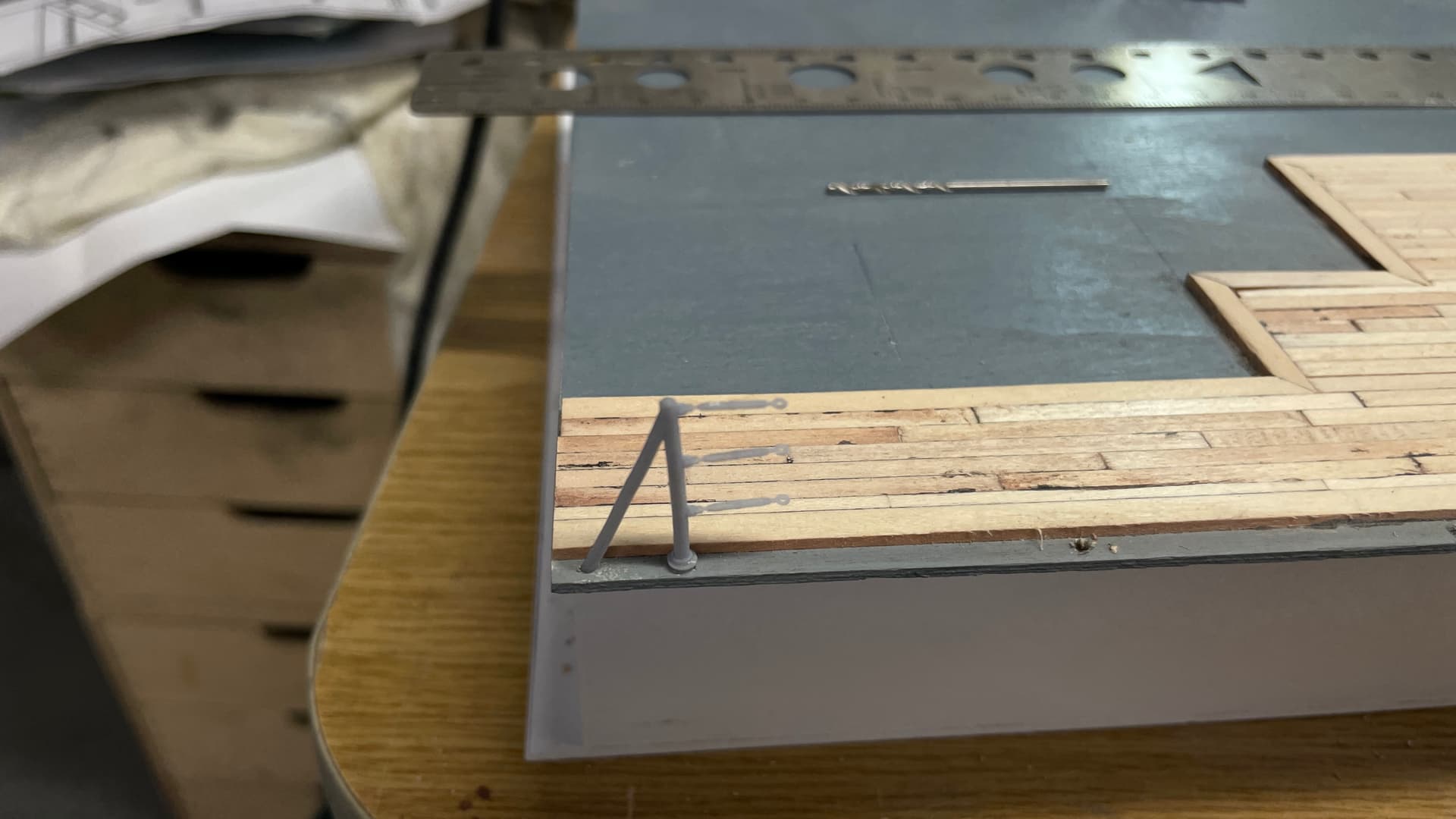
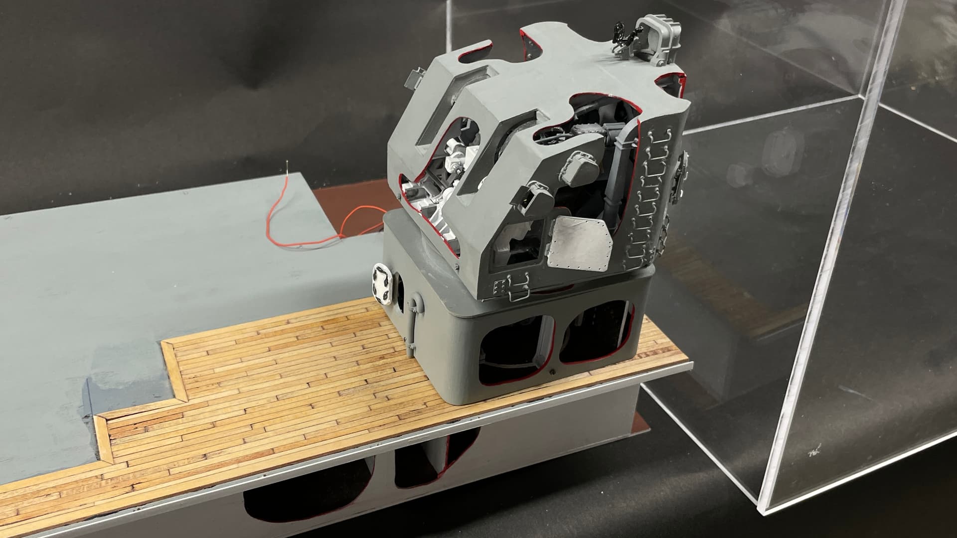
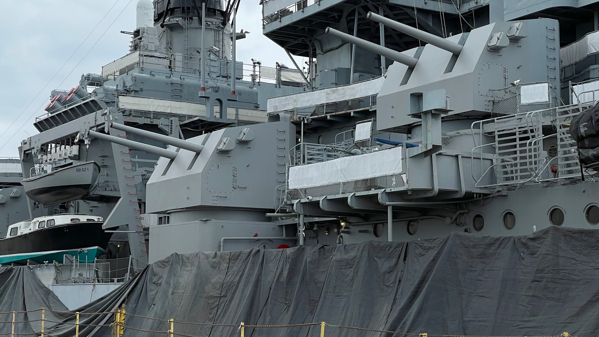
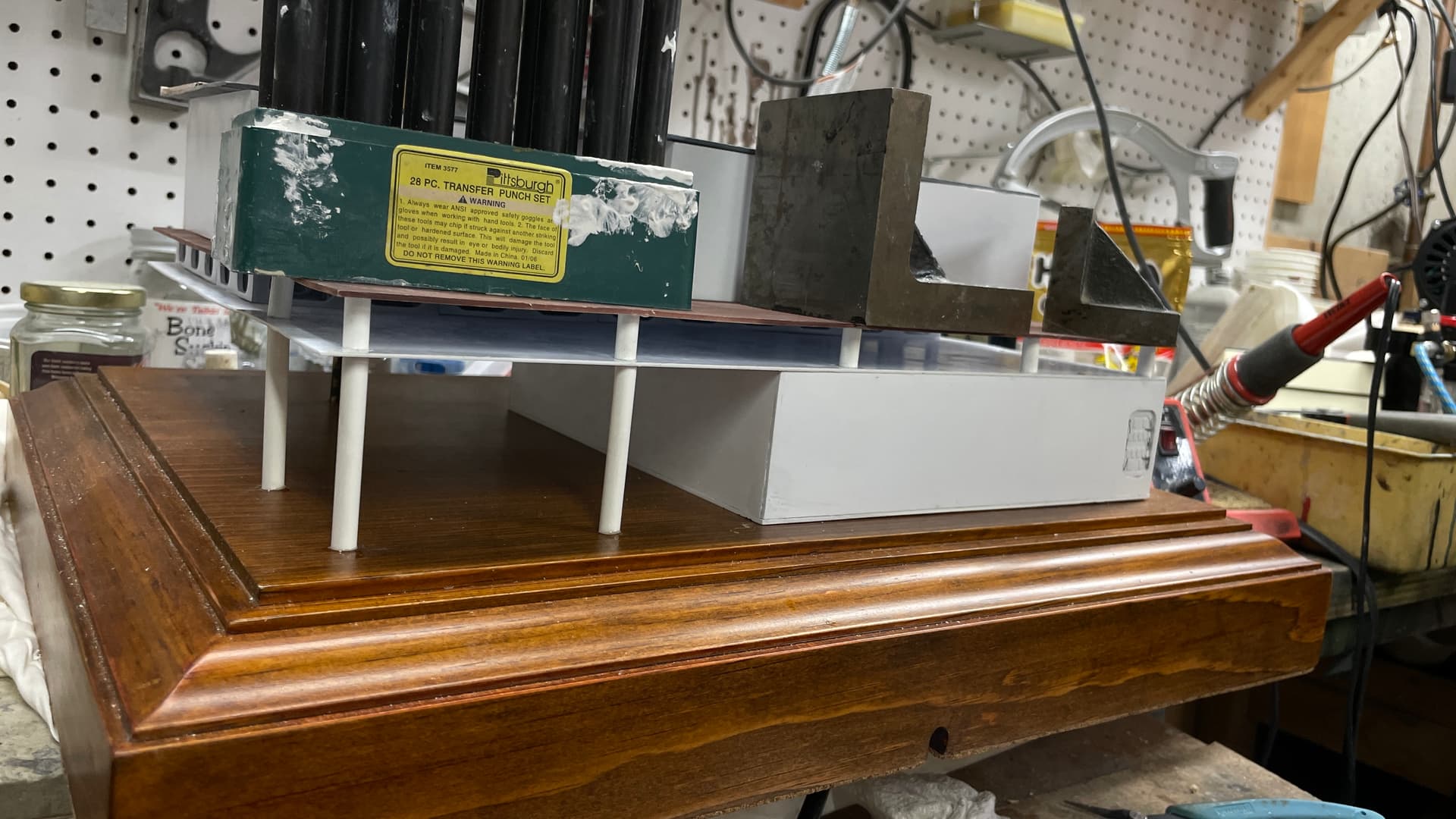
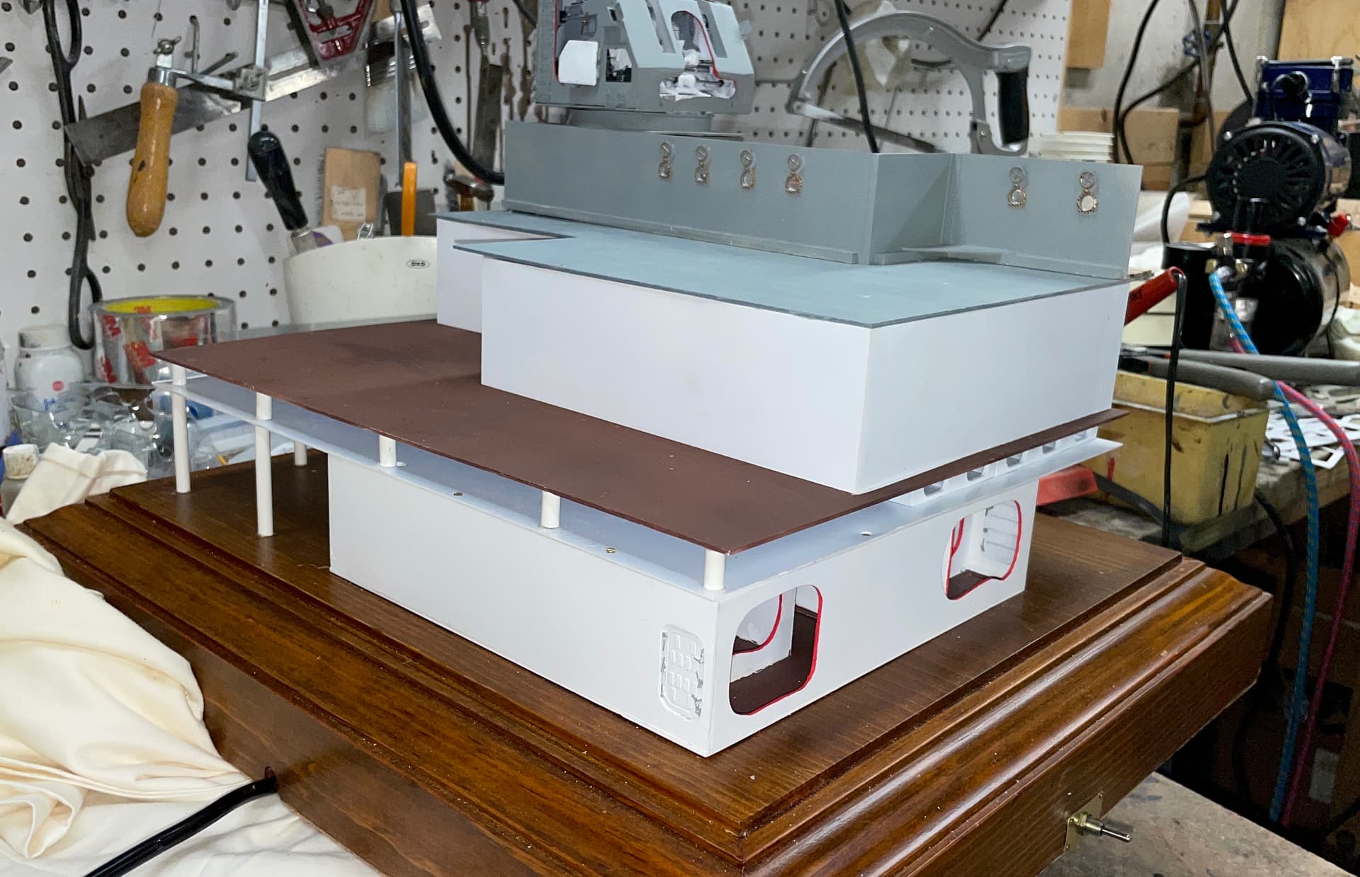
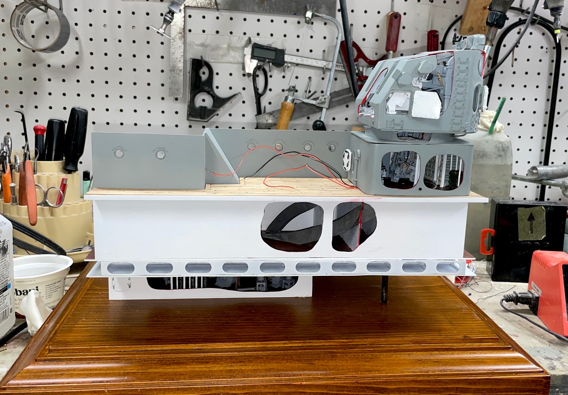
I also took some detail shots of the secondary battery I’m modeling to capture any other external details that I want to add.

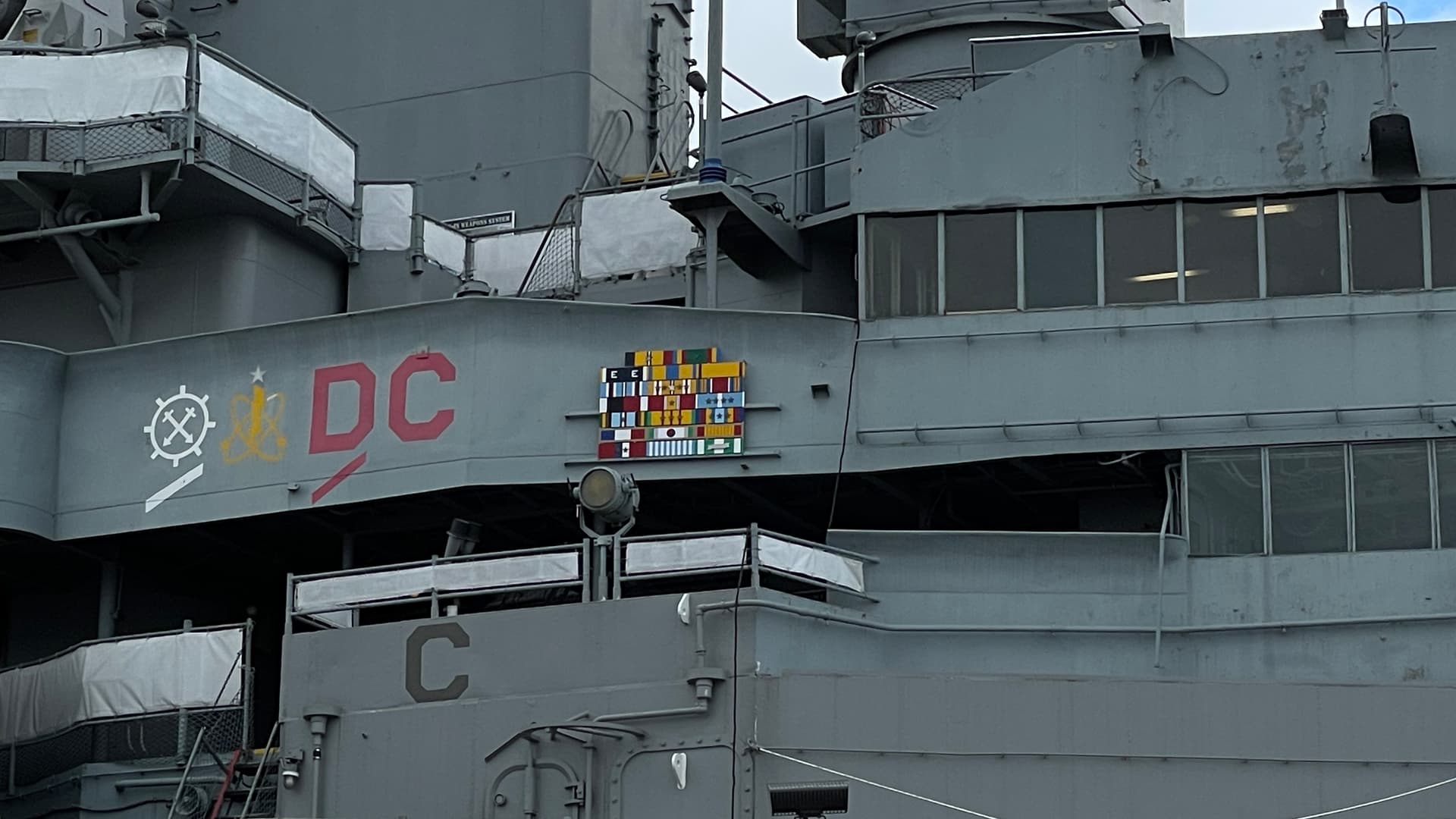
The Big J was the most decorated warship in the US Navy due to its many deployments. It has battle stripes just like an individual sailor would have.

We had a private tour with Ryan that lasted 1.5 hours. It was remarkable and I’m so very glad to have been able to do it.

9 Likes

Back in the shop. Finally got those trunks installed. I’m not happy with the little chunk on the right. I had to do major surgery on that one to get it to fit. Reason… the trunks are too far forward and the curve would take it out of the structure. In retrospect, I should have installed the trunks before the main deck was screwed down. It was very difficult to position and glue them through those cutaways. Water over the dam!

I cleaned up the mess I made of the decking and paint within those openings, and then re-glued the assembly together. With the adjusted lower trunk parts, the deck nestled down much tighter. Tomorrow I will install the gun house and UHR and run the wiring to the underneath. Last thing before putting on the case will be to install the delicate railing.

I still have to finish the case with flame polishing the edges and mounting the plaque and graphics. I need to build the case lock. That doesn’t take too long. Ideally, the model will be done by the end of the week. Then I have to plan another trip Back East to deliver it. The ship will be back at the Camden Waterfront in mid-June.

9 Likes

awesome write up Myles!
The BattleScale Collectica Show

1 Like

Awesome, thanks for sharing. :+1::+1:

1 Like

Looks like a superb trip & tour…

Thanks all! It was all of that and more. When I went into the upstairs bedroom that has my Missouri model, I have an even deeper respect for the ship and those who designed and built it. It was an honor to touch its sides in a way that most mortals would never experience. I really want to go see it again because I’m sure that I missed something.

I woke up thinking about other ways I could have set up the model including printing 1/2 of the gun house shield as a single part eliminating all the alignment and fit problems. Instead of a cutaway resembling Swiss cheese, it would be 1/2 housing and 1/2 wide open. That’s if I ever have to make another one of these.

I’m a bit over one more day until completion. Did a bunch of punch list items including actually punching something. To make the glazing for the portholes, I sharpened the tail end of an F drill which perfectly matched the i.d. of the porthole opening. I punched out 0.010" clear styrene. The first grind was a V-shaped which distorted the plastic discs too much. I re-ground it to a simple flat, slanted end and punched out acceptable discs. After inserting them, I used Pledge floor wax with Future (clear acrylic) which served to clear up the pieces and glue them into the opening.

After taking the pic I painted the inside frames brass.

My design, not having the Splinter Deck covering the entire surface of the 3rd Deck, was chosen to simply reduce the amount of printing of unseen parts. However, it created a rather flimsy cantilevered structure. To inprove structural integrity I cut and epoxied supports across the under-supported back. This stiffened the whole structure nicely. It won’t be noticeable. The model will be backed against a wall so to see the rear will take some doing.

Here’s how it looks with the gravity clamps.

I first used plastic cement to hold the supports to the styrene parts, but they were failing and redid them with J-B Epoxy blened for plastics.

I glued the superstructure wall in place in readiness to add the gun house/UHR tomorrow.

I flame polished the exposed edges of the case and installed the name plaque and the graphic. The plaque already had adhesive strips. For the graphic I used 3M Transfer Tape.

I was unhappy with the misaligned front hoist trunk. I added a thin styrene apliqué to clean up the contours. It’s just a thin piece of styrene sheet, but you can’t see around it.

I chemically darkened the conduit tube that serves double duty: providing a path for the GH light circuits, and added support for the overhanging area. I added CA to the top and bottom to make sure it stays put.

What’s left is making the case locks, gluing the GH/UHR to the deck, adding the stair, building and painting the railing and tieing in all the wiring to the circuit board…. and it will be DONE! Could be tomorrow. The glue I’m using (J-B Structural Adhesive) takes a few hours to set up so maybe it will be Monday.

10 Likes