5"38 Cutaway Turret Complex; CAD and 3D Printed

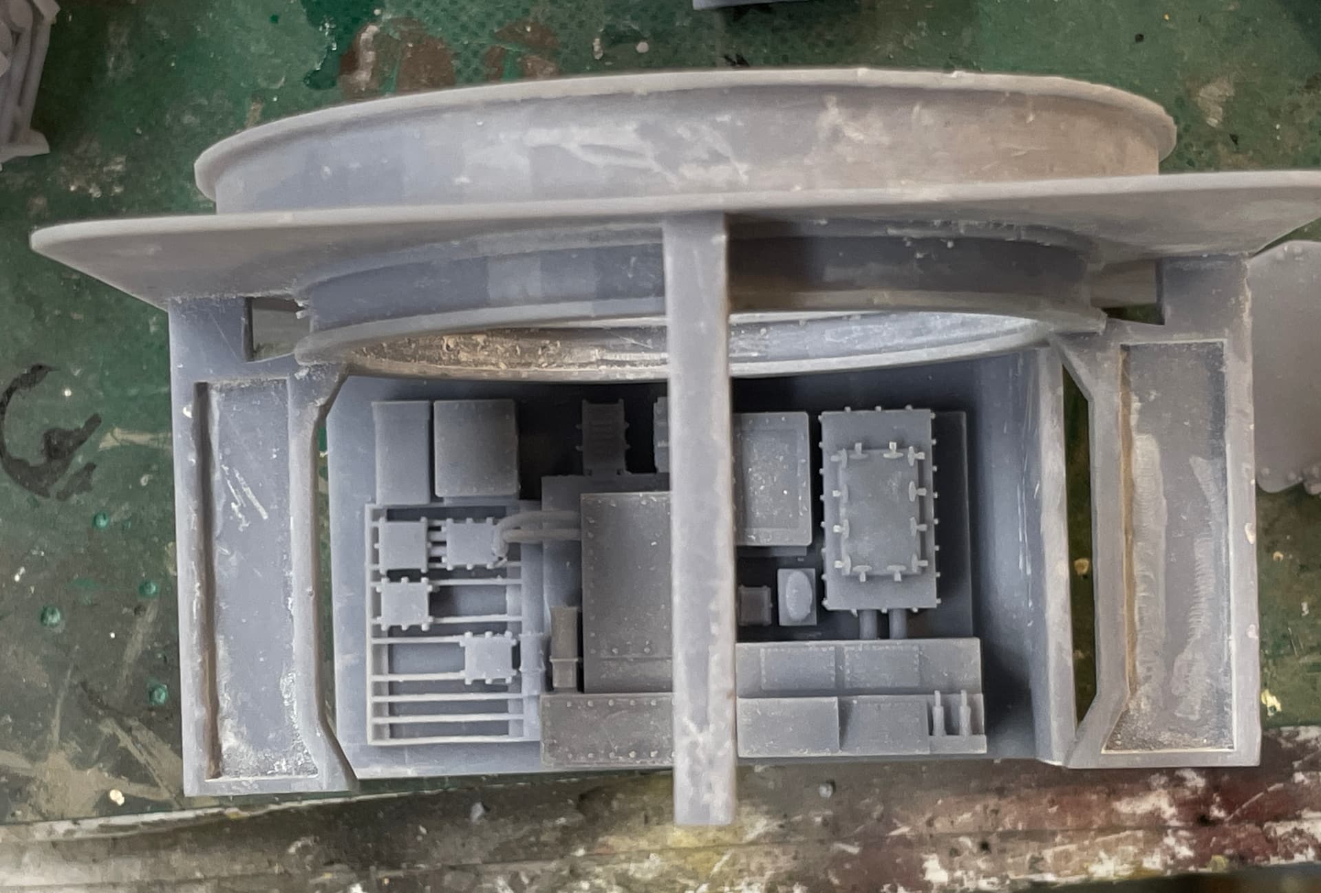
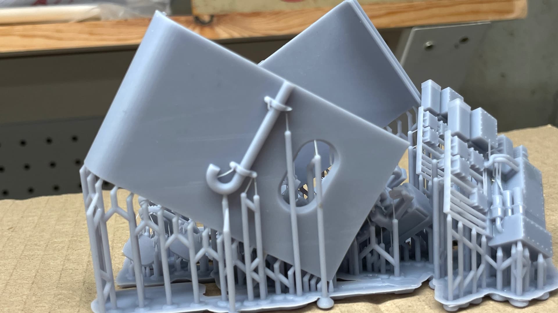
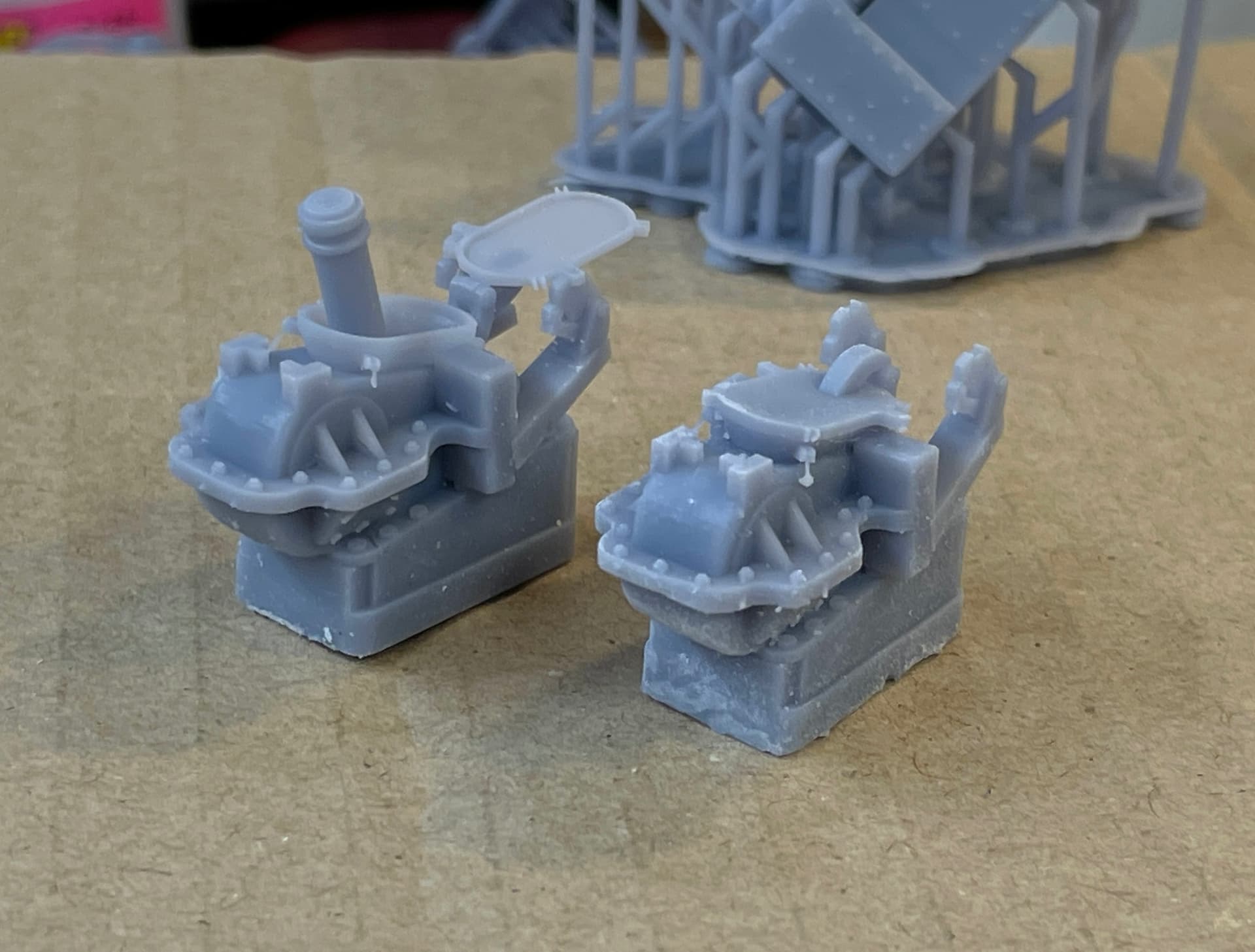
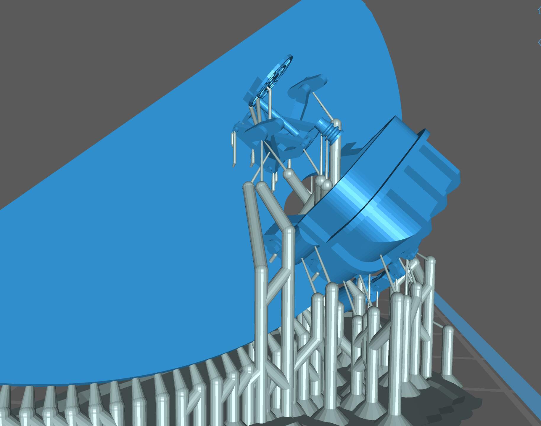
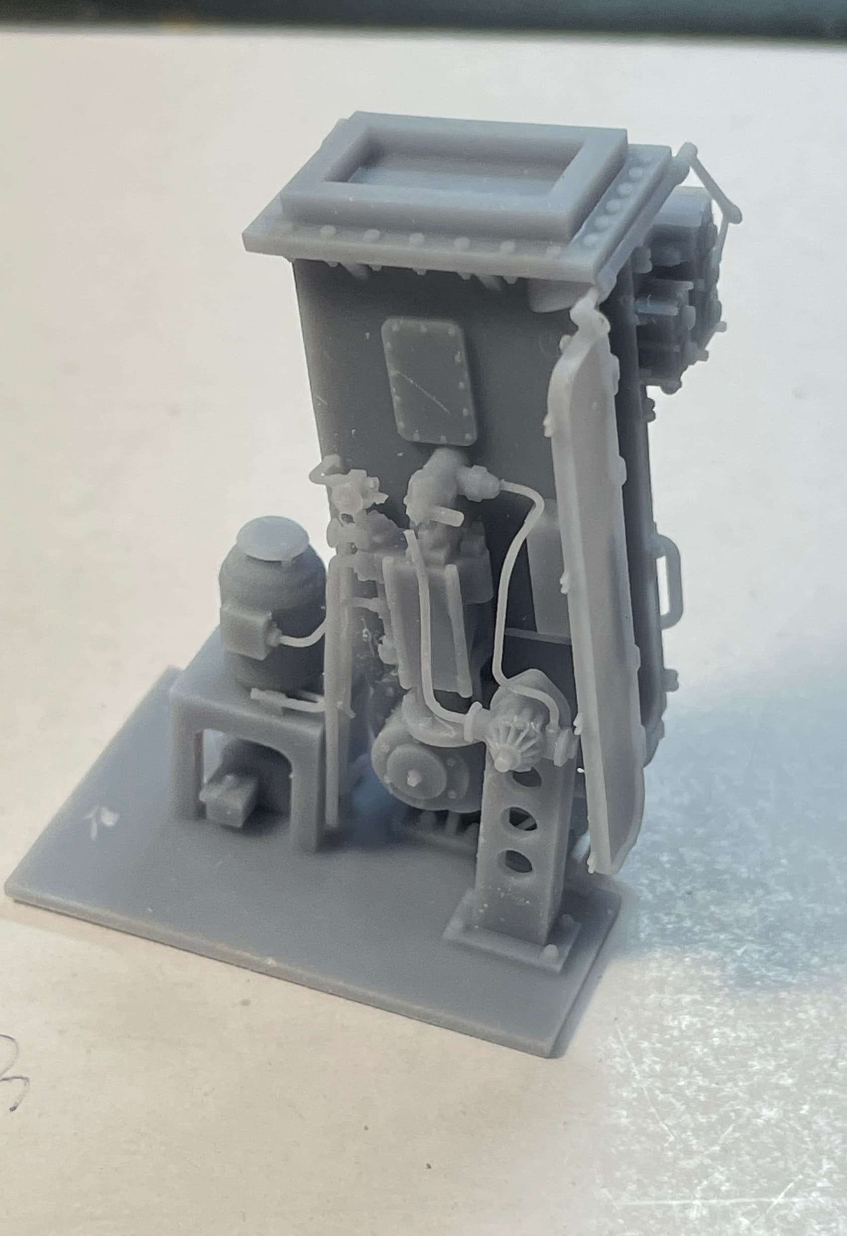
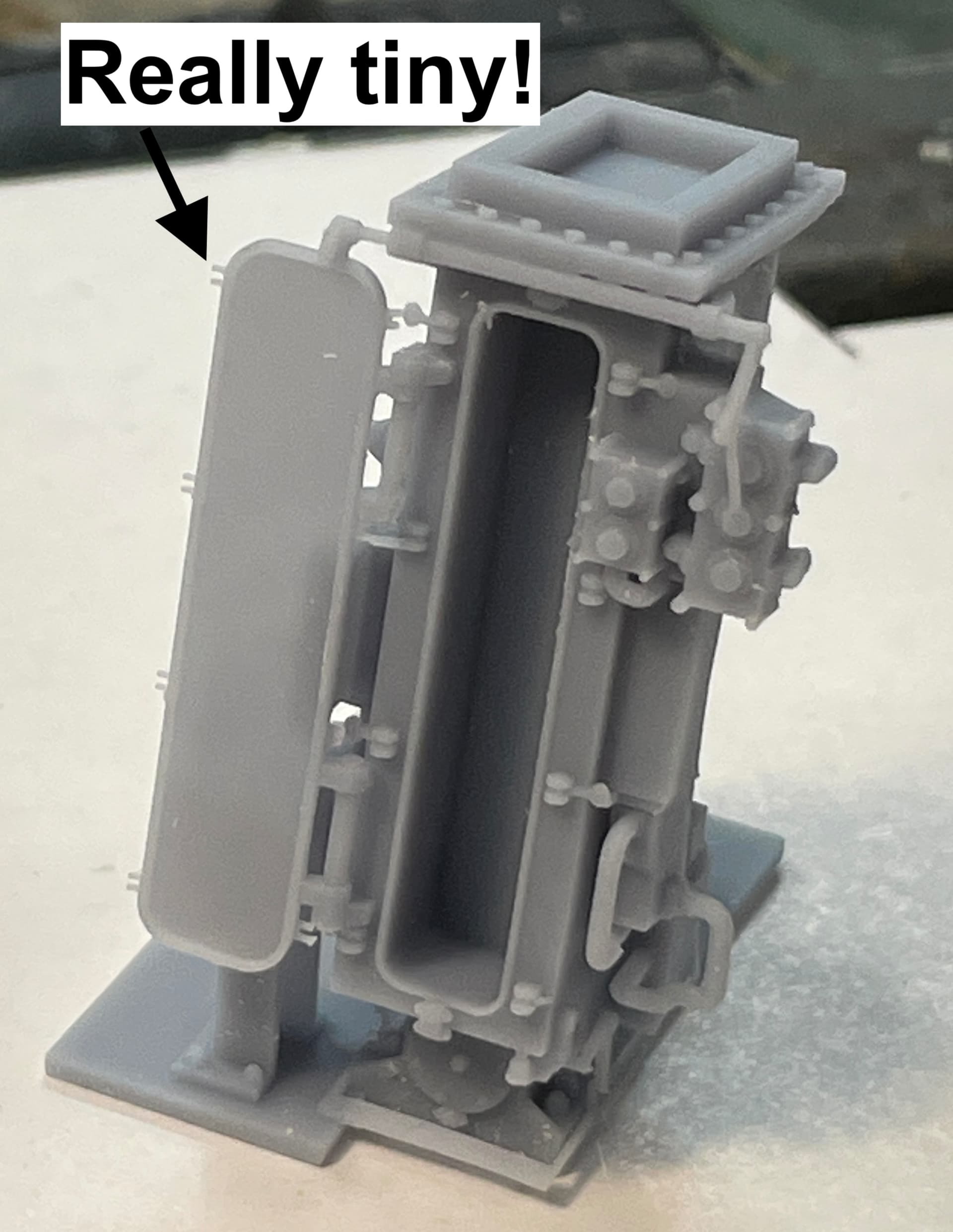
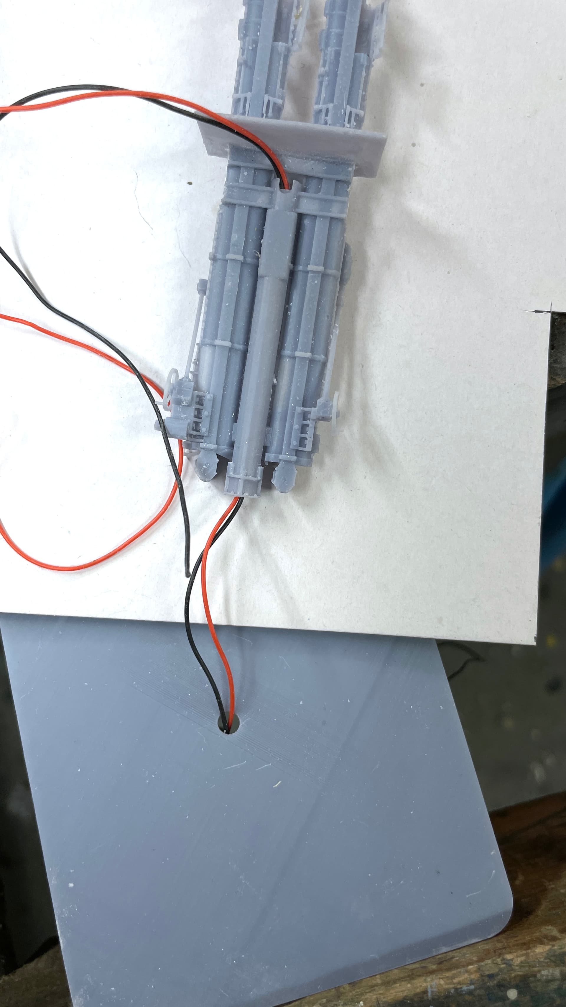
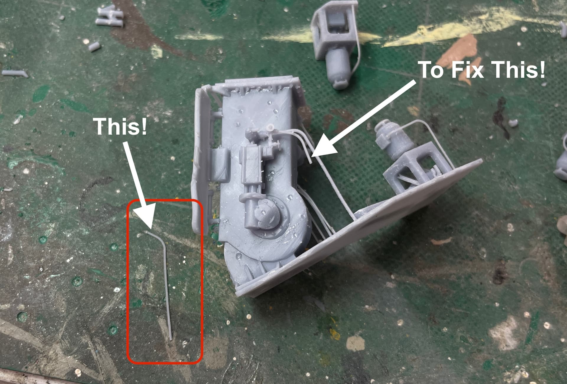
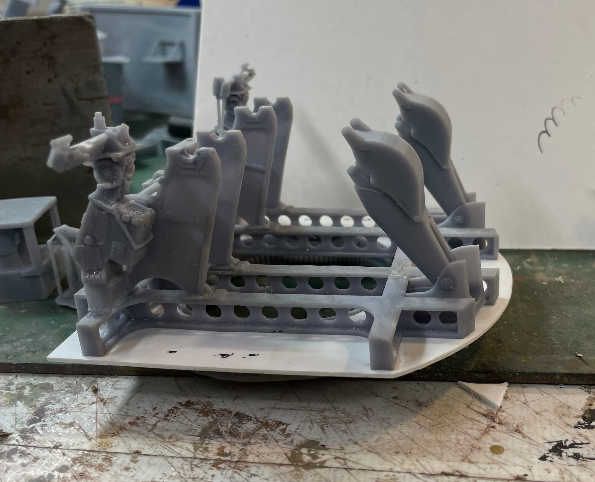
It took some extra effort to create the full ammo racks with the cartridge tanks and projectiles showing the illusions of all the ammo, but with some trickery to use less resin and make the print simpler. I got input from the SketchUp forum on how to simplify the drawings. I just pulled a huge print off the machine including all the ammunition racks for the Upper Handling Room (UHR). With the 3.1 second exposure, it seems that everything I want to print, prints, and prints perfectly. Moreover, all the tiny features have strength that I didn’t think was possible. Case in point. Get a load of the Gun Captain’s fold down platform. The side supports are really fine, but strong.

This post is going to have a lot of varied stuff.

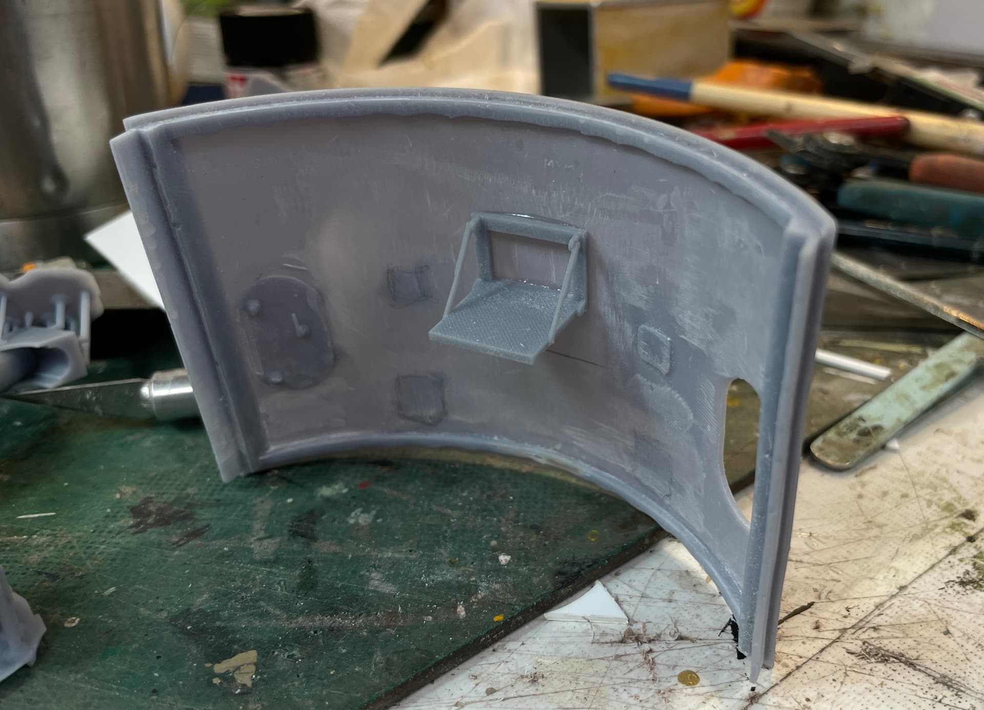
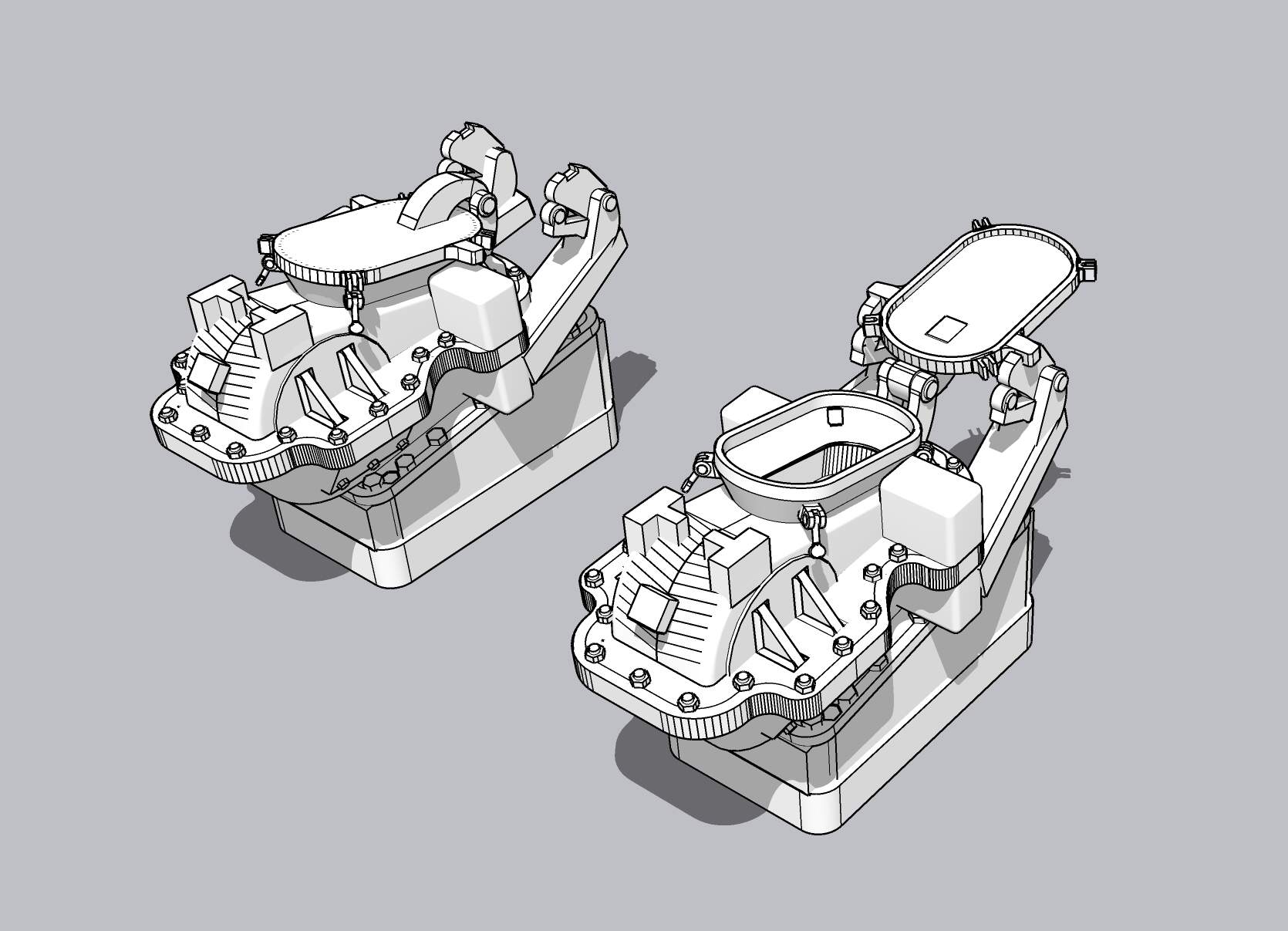
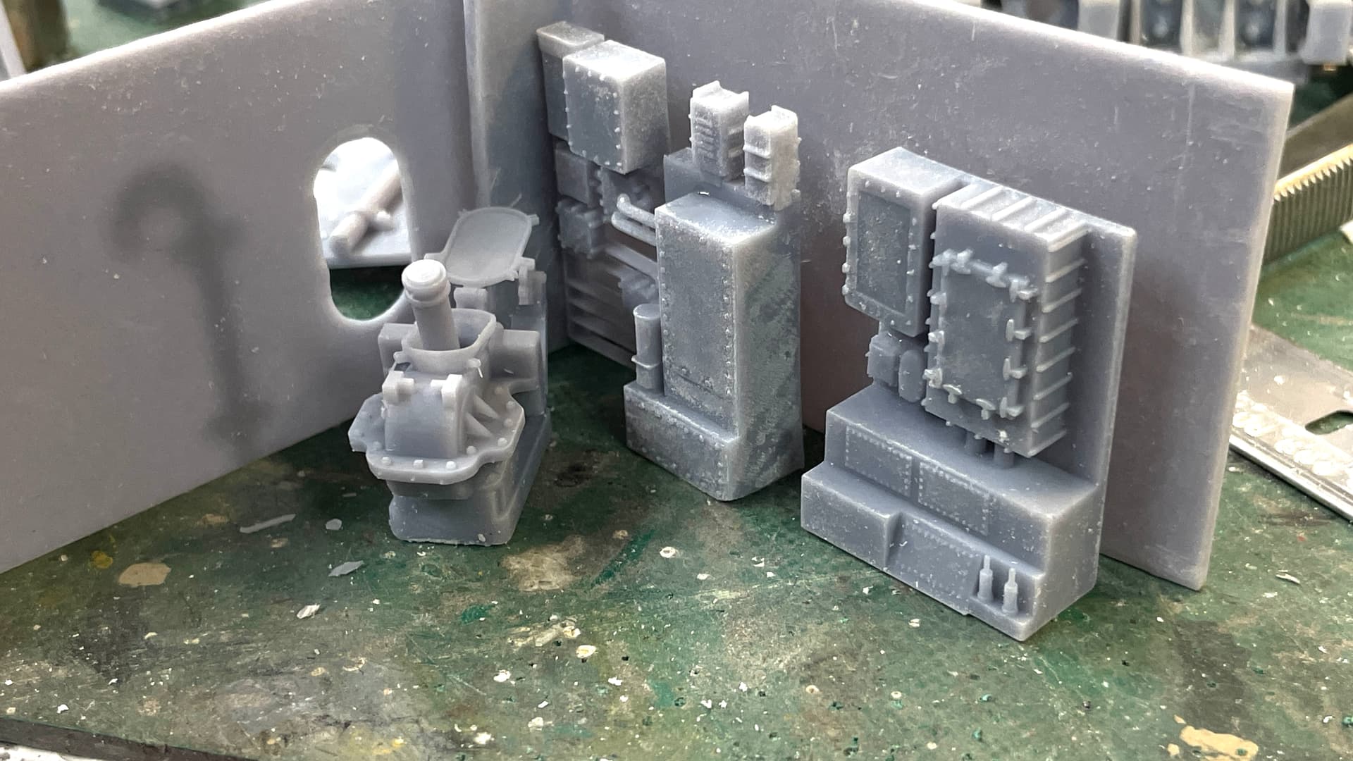
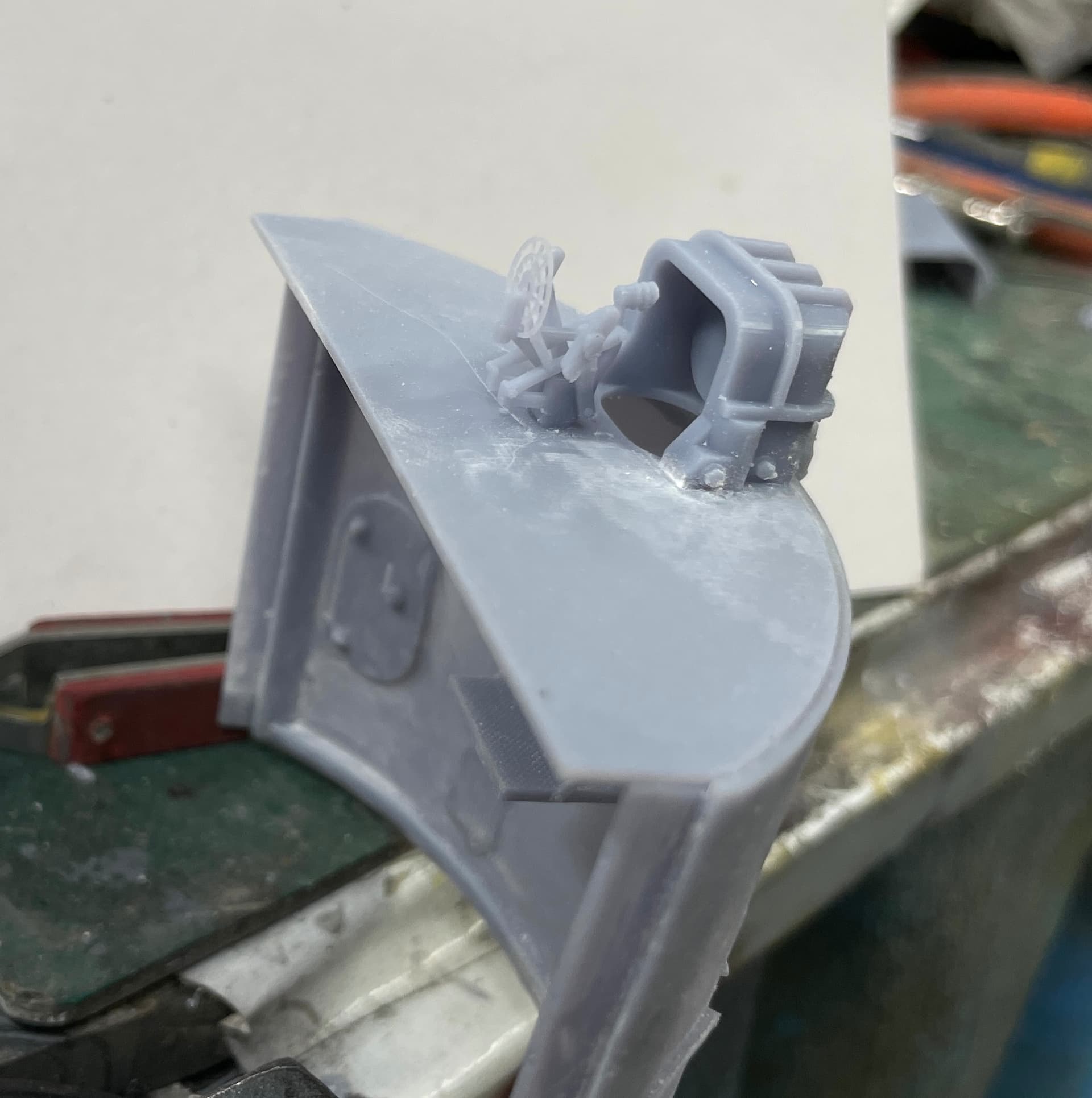
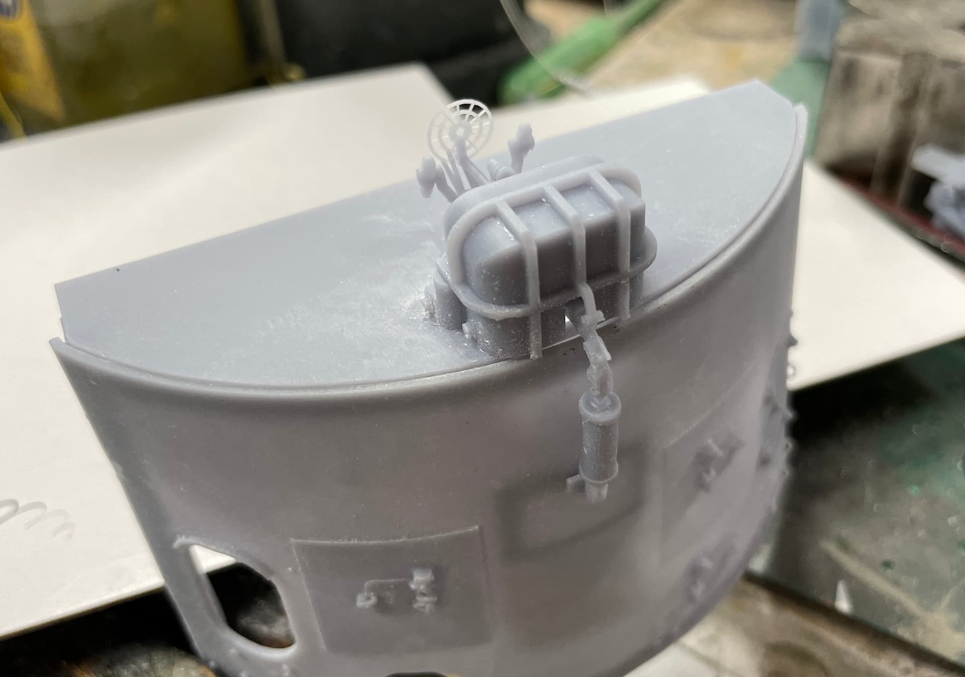
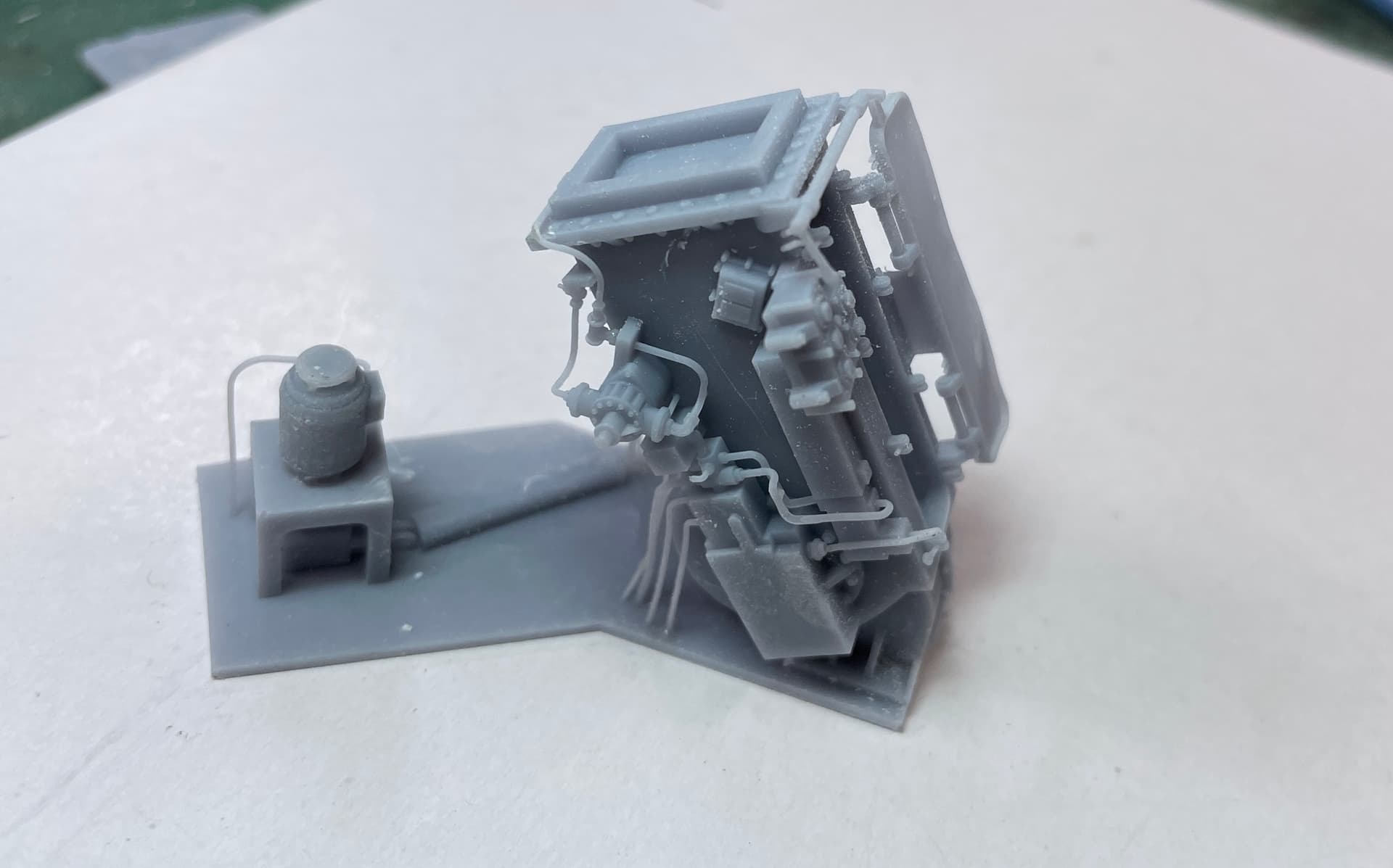
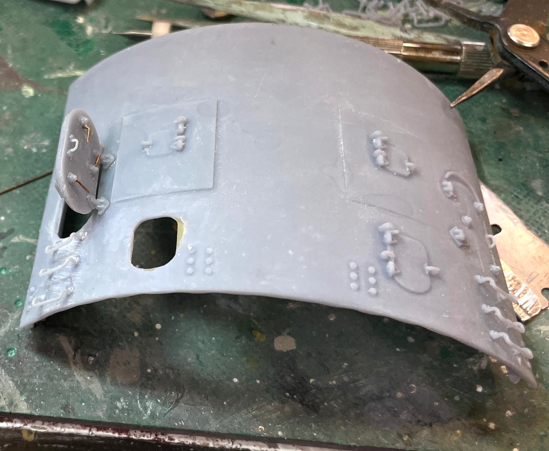
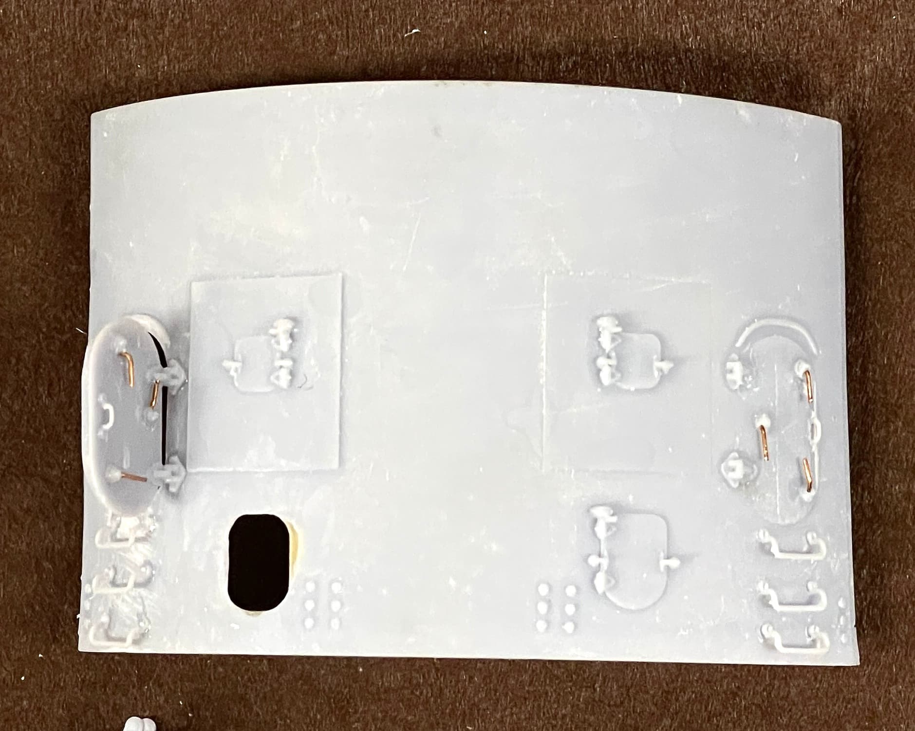
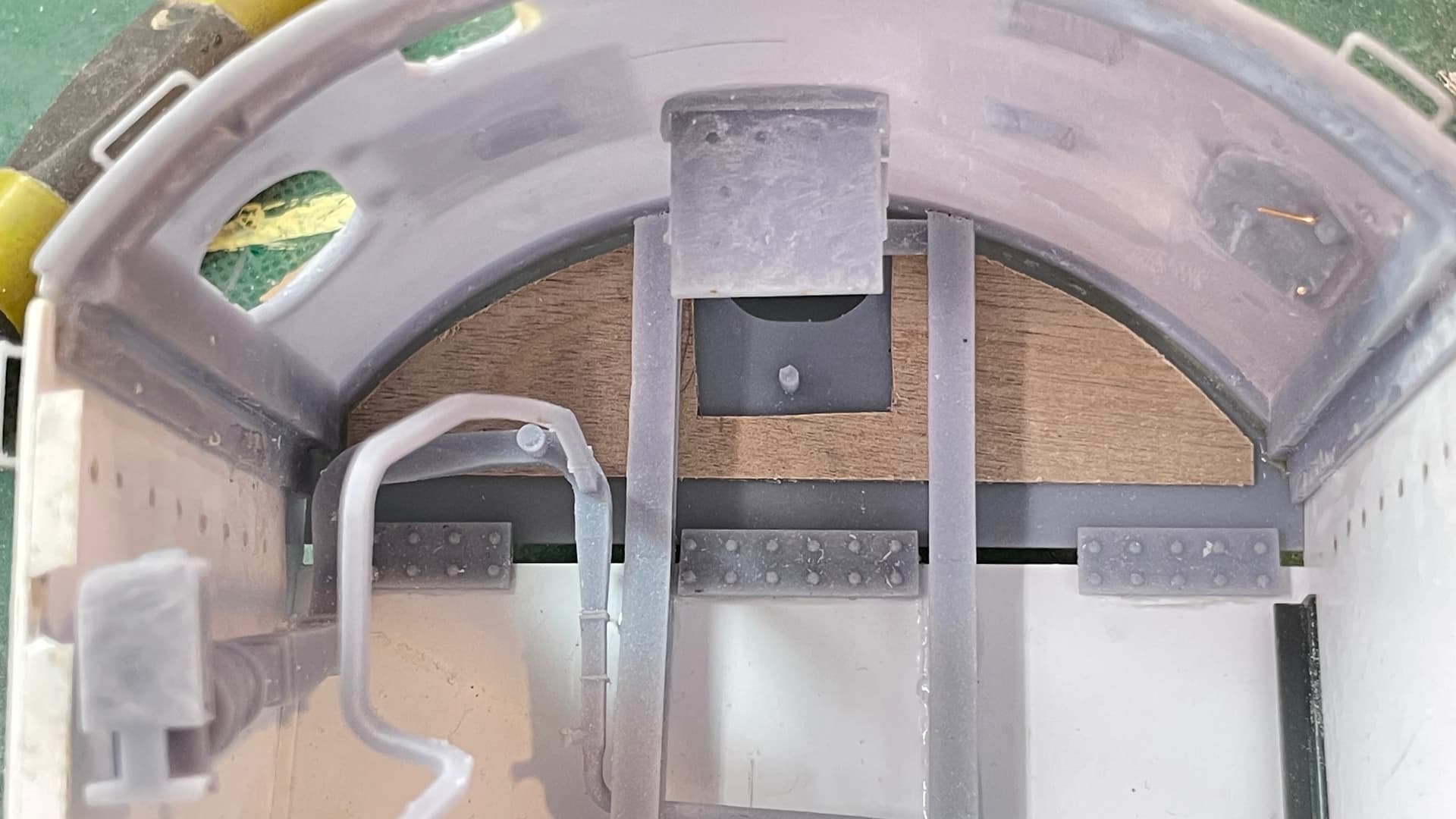
I drew this part so the back frame was curved to conform to the curved rear wall and this worked nicely.

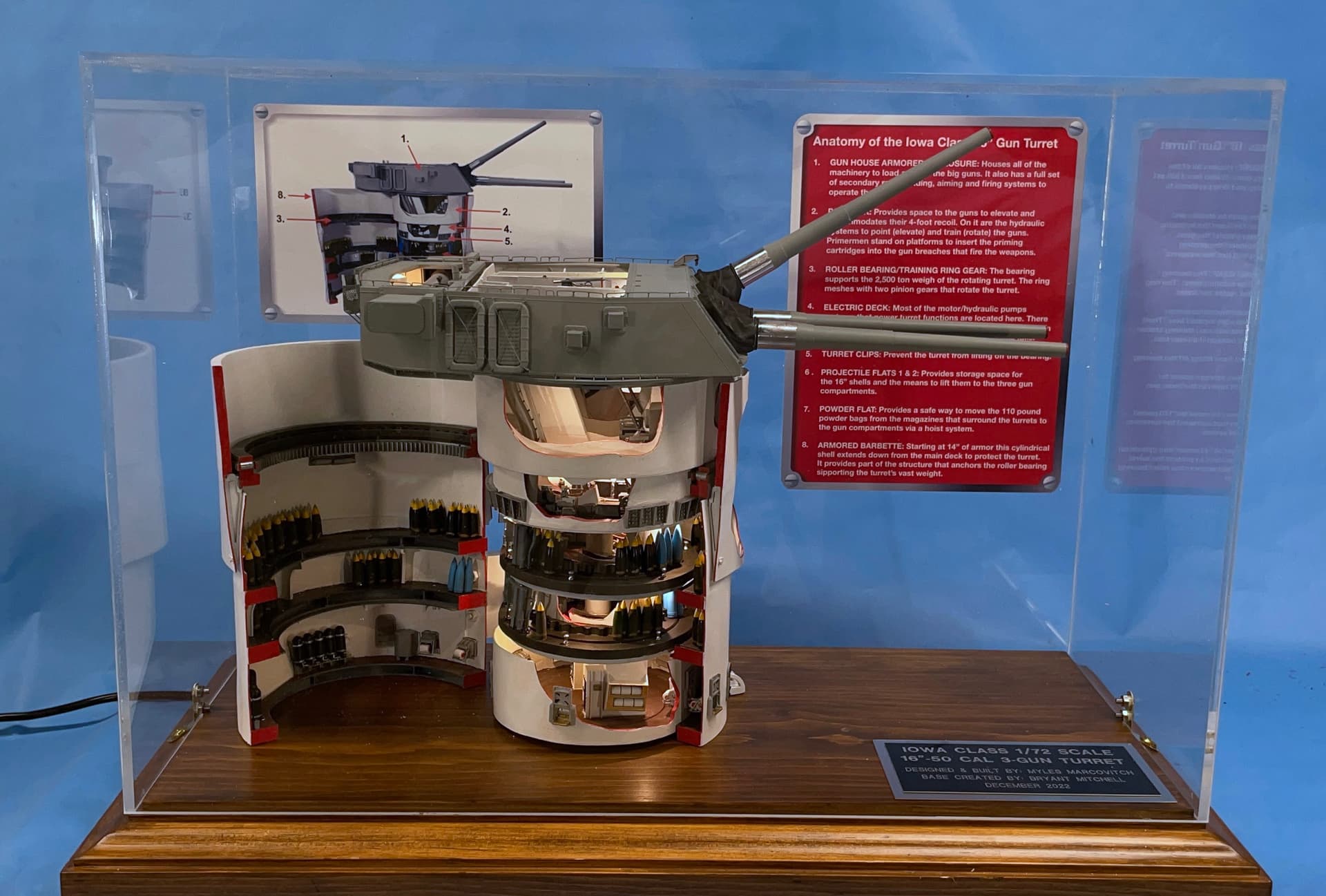
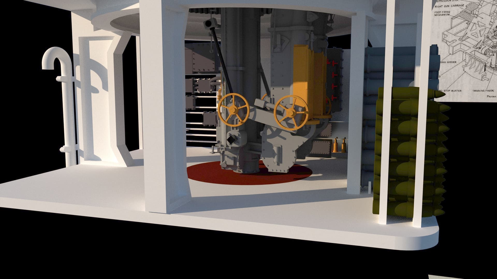
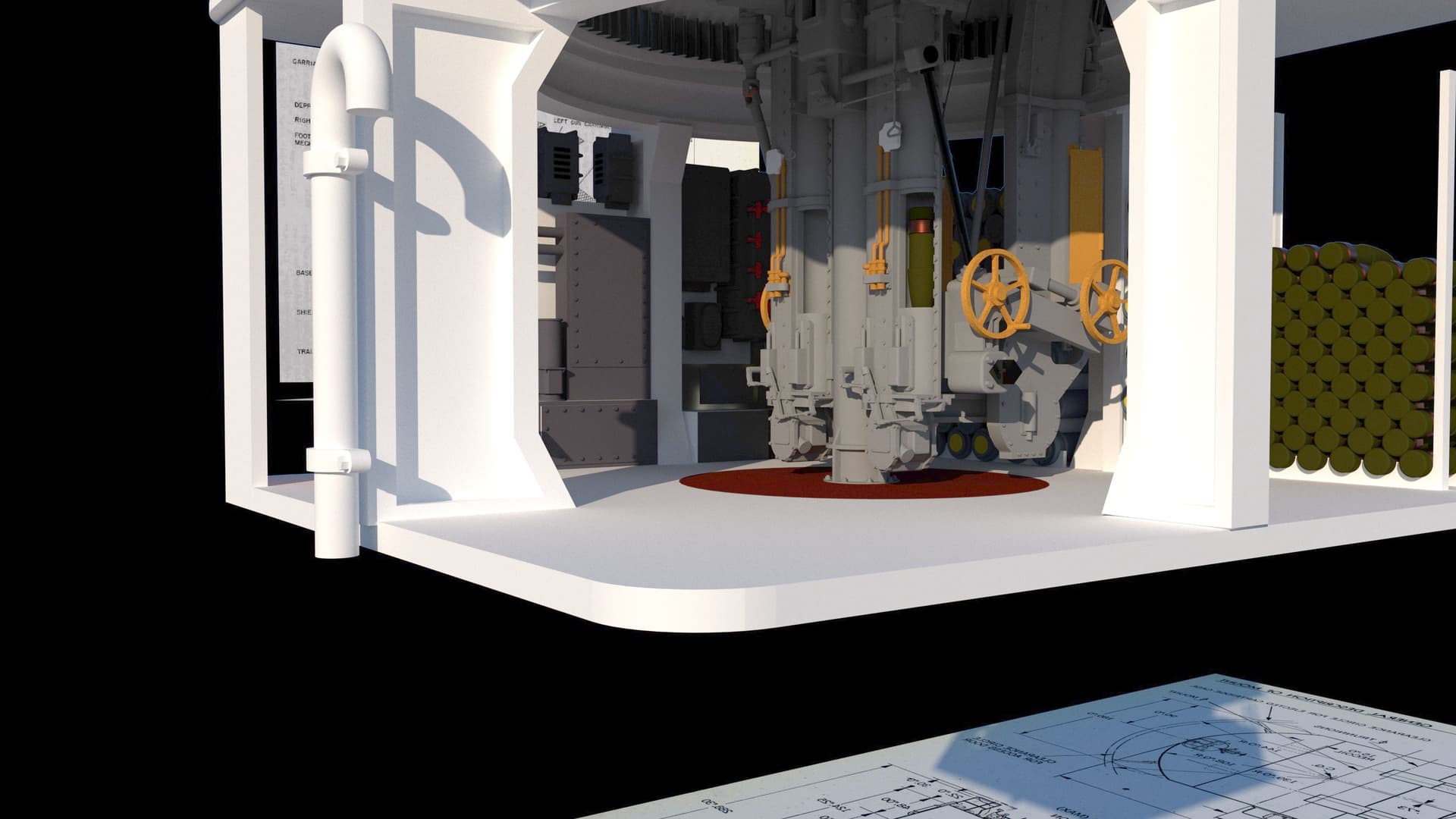
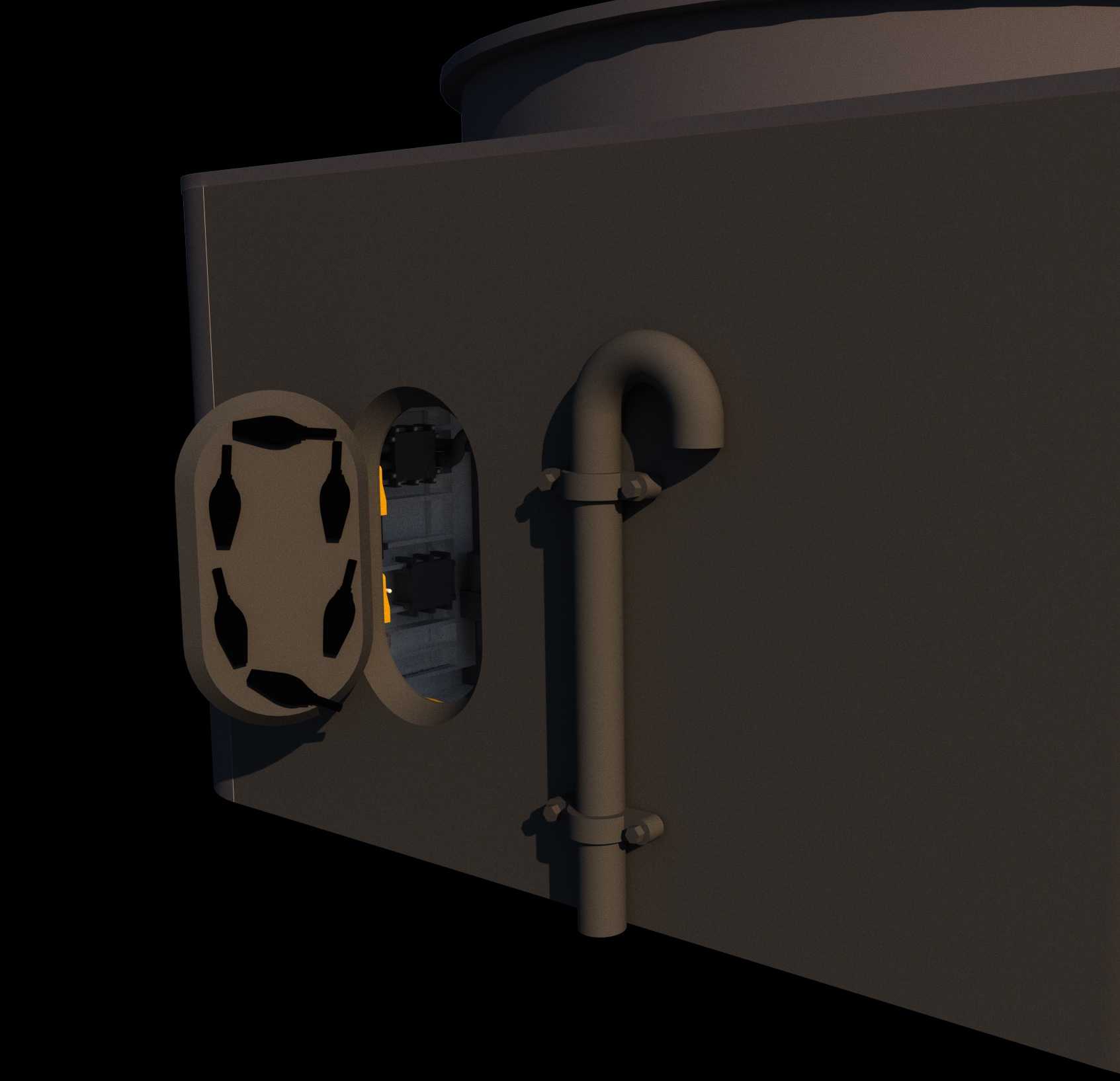
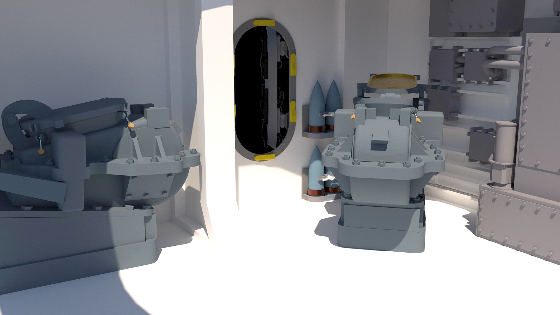
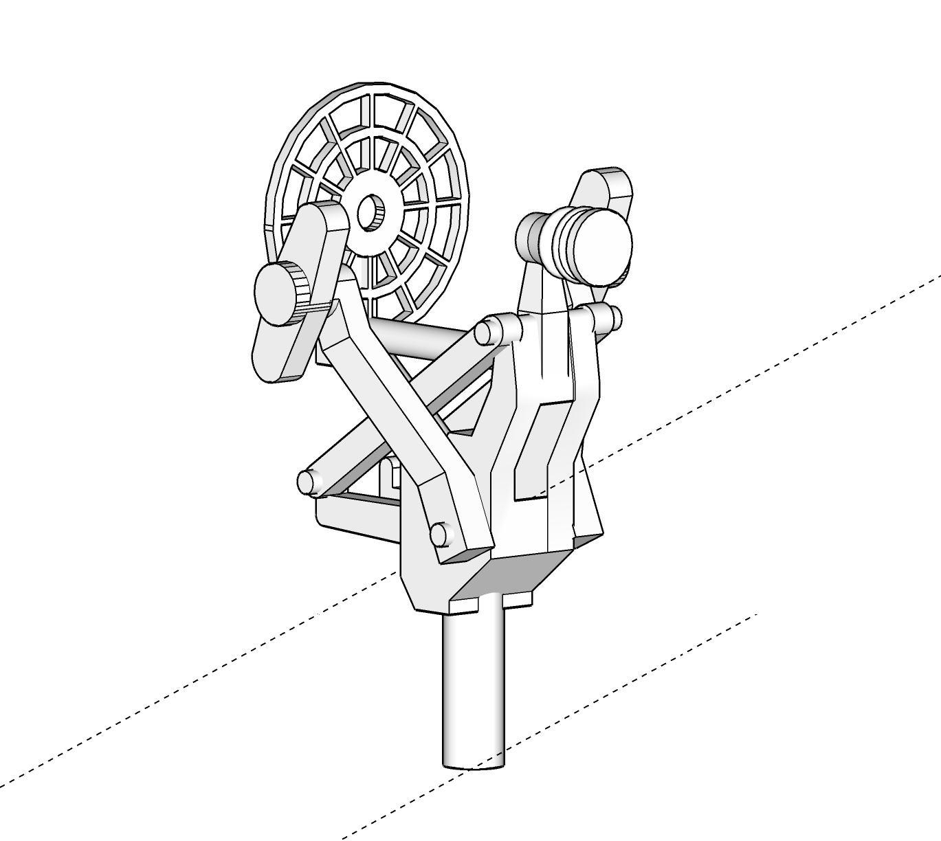
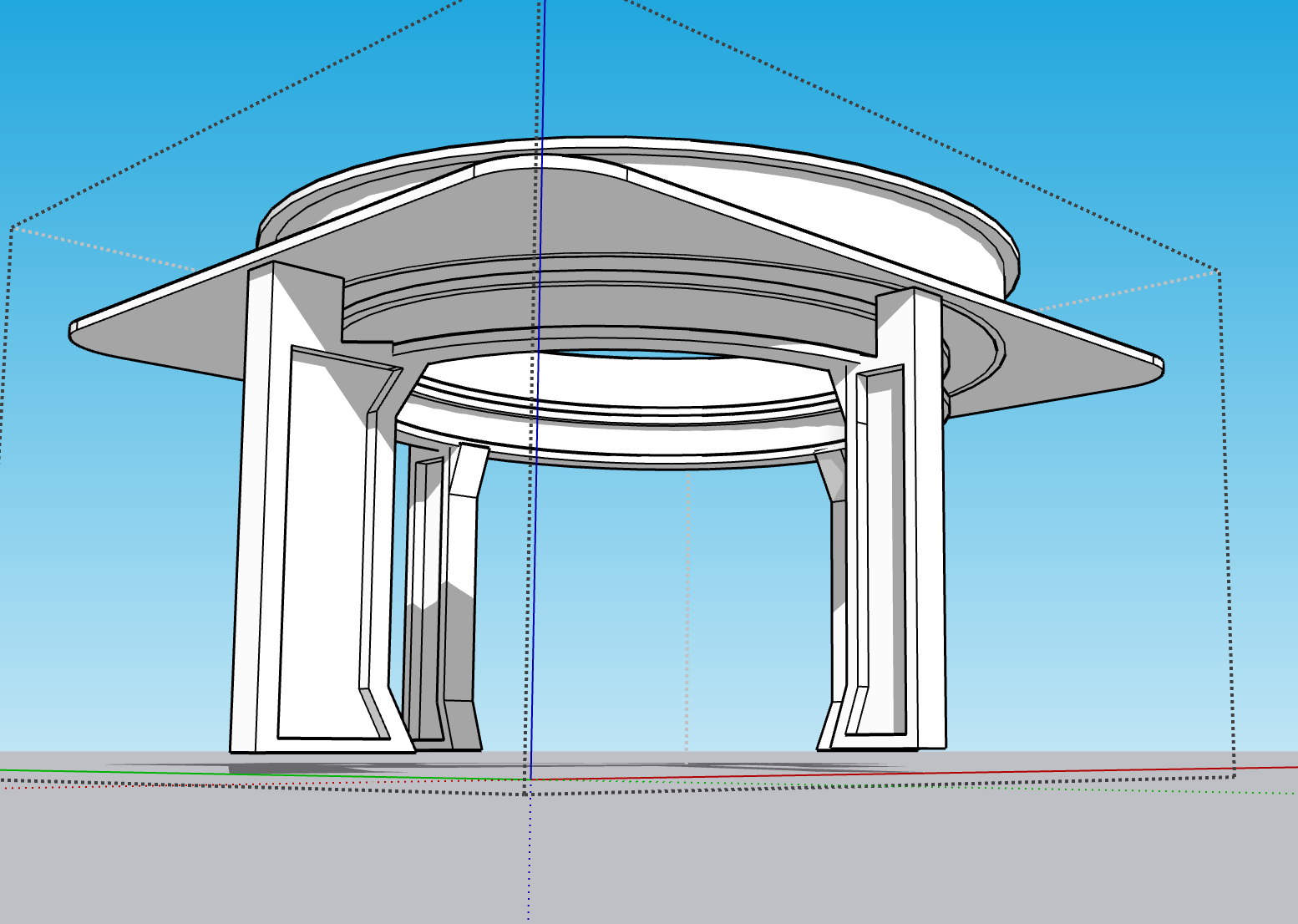
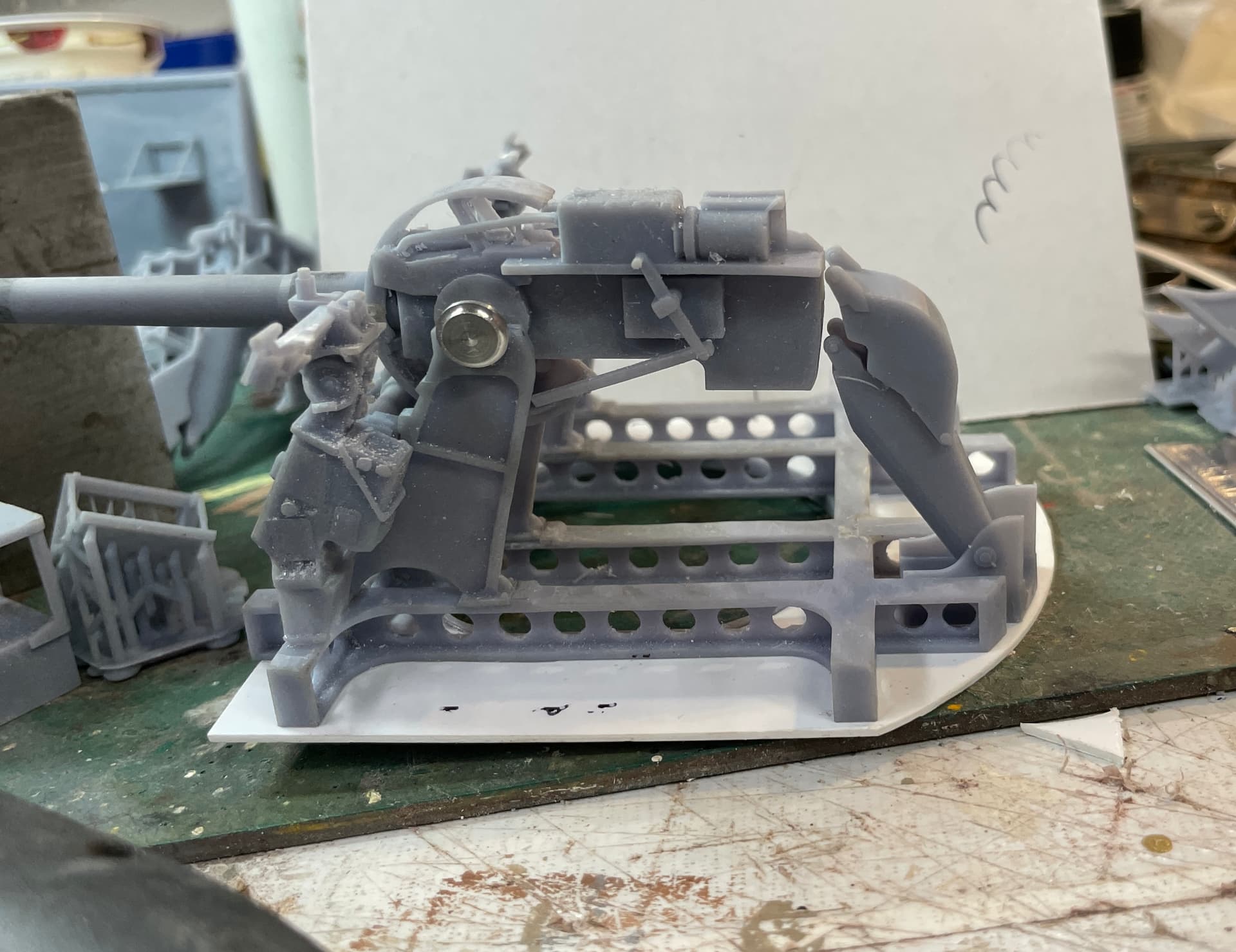
I drew and printed the massive support girder ring that holds up the massive weight of the entire rotating structure. There are form legs that support the ring and take the load into the ship’s structure. The walls of the UHR doesn’t actually support the gun house. I chose to draw and print the ring and legs integral with the UHR roof and the armored ring that surrounds the actual base. This includes the weather seal ring at the top. This was I was ensured that the ring would be centered with the rest of the structure.

Here’s the drawing:

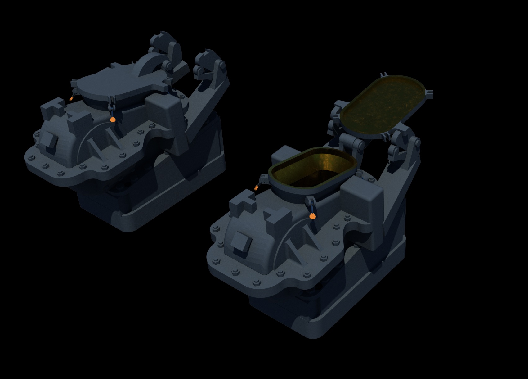
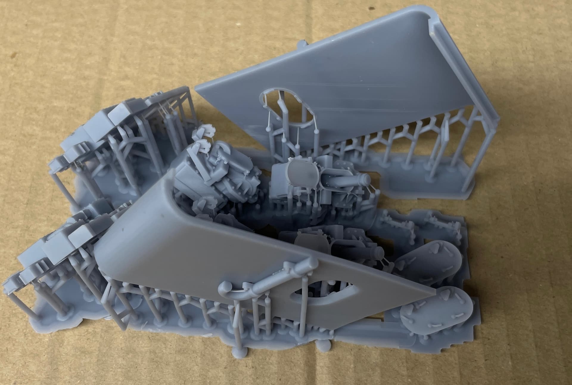
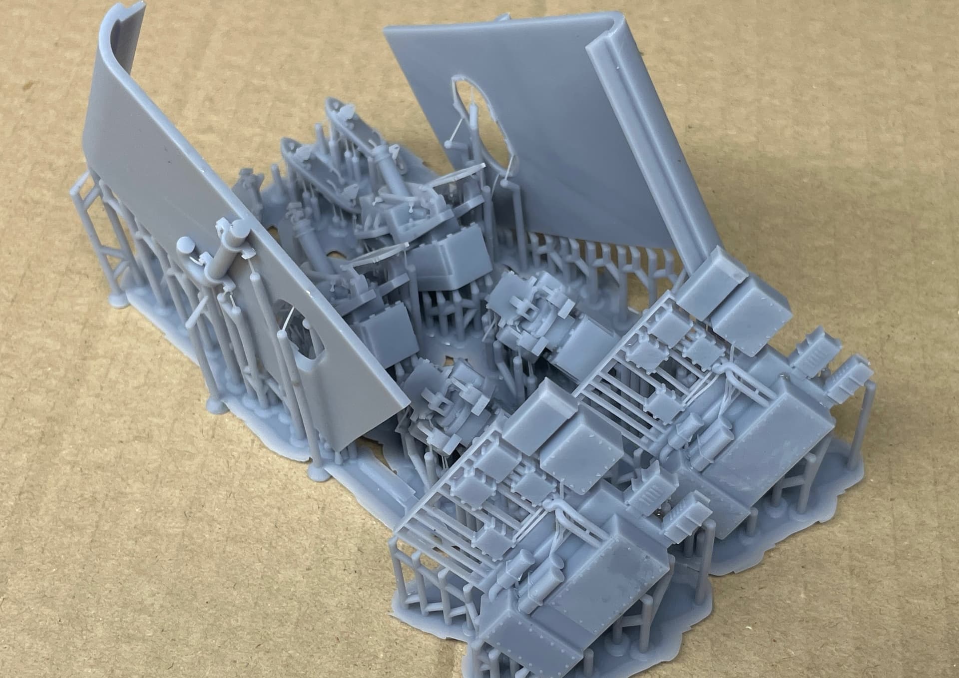
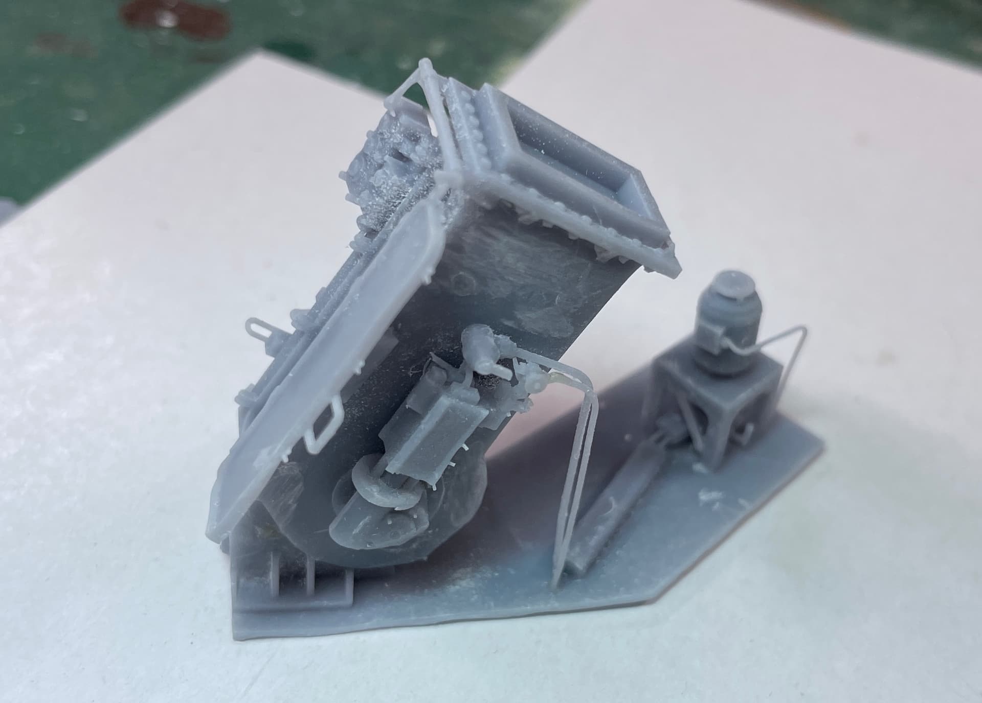
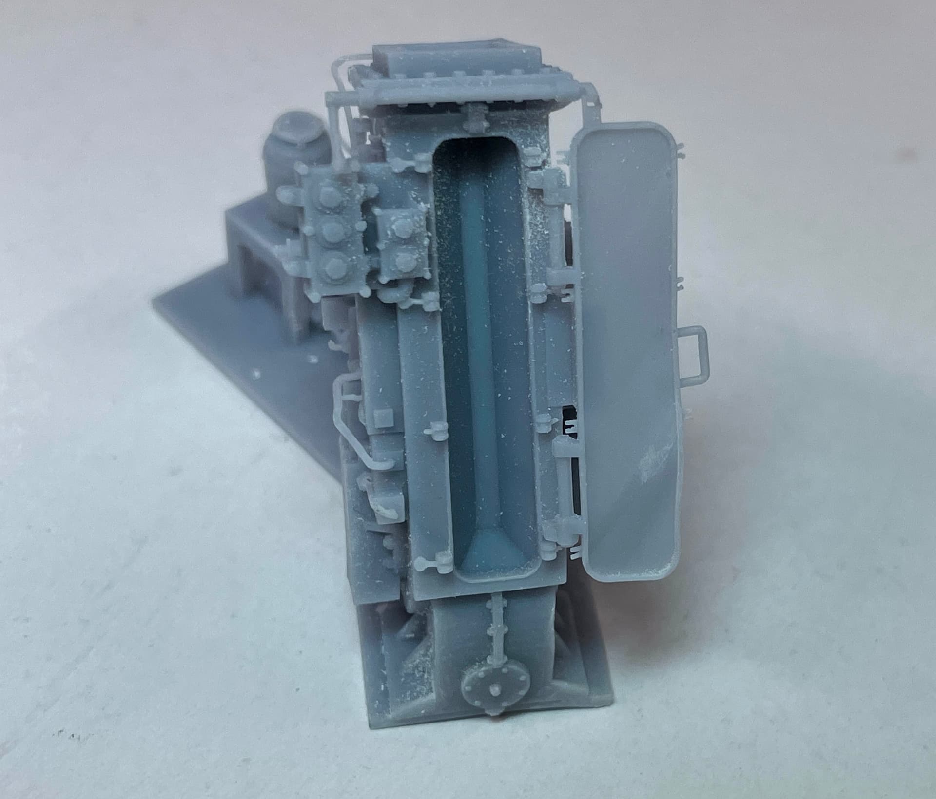
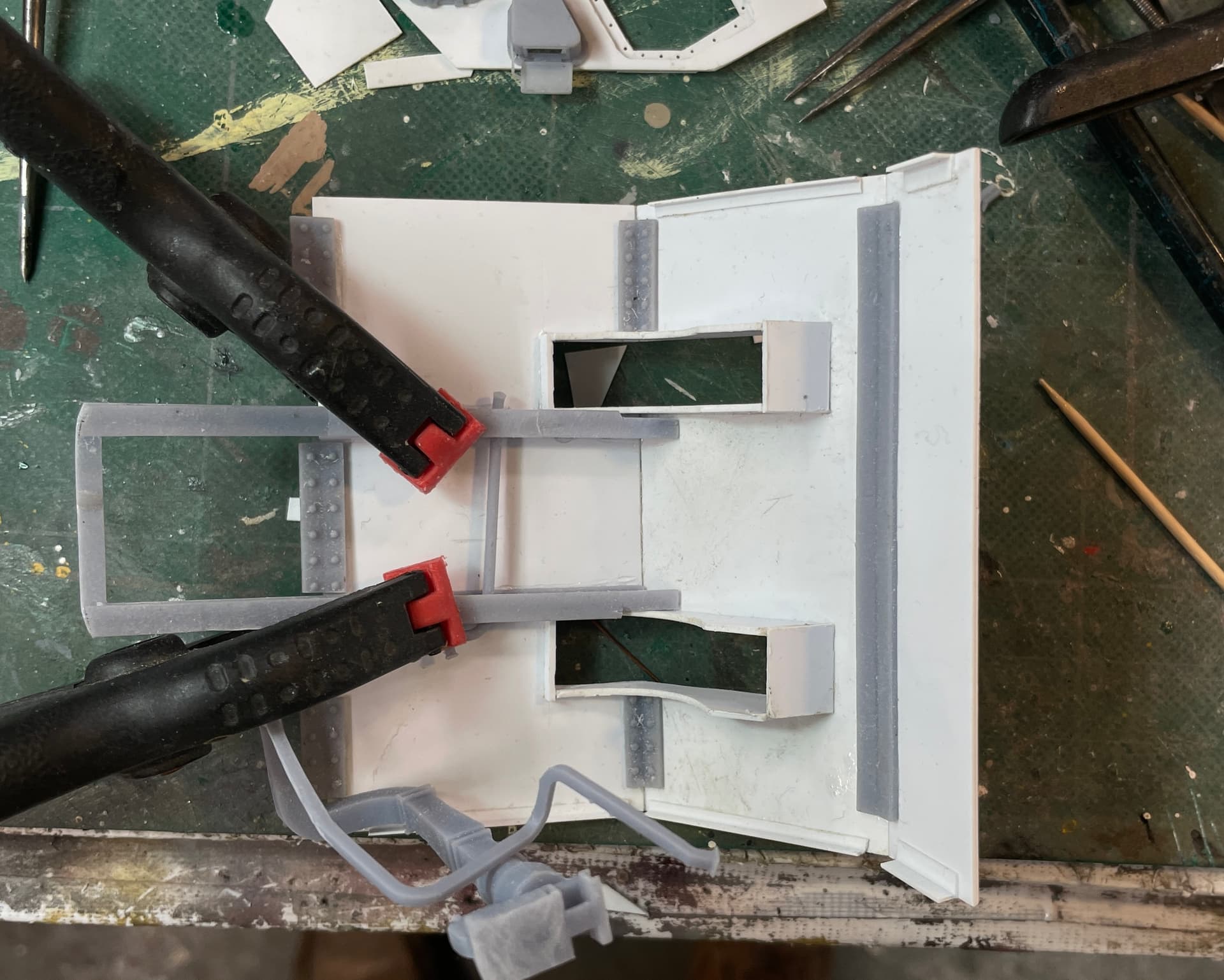
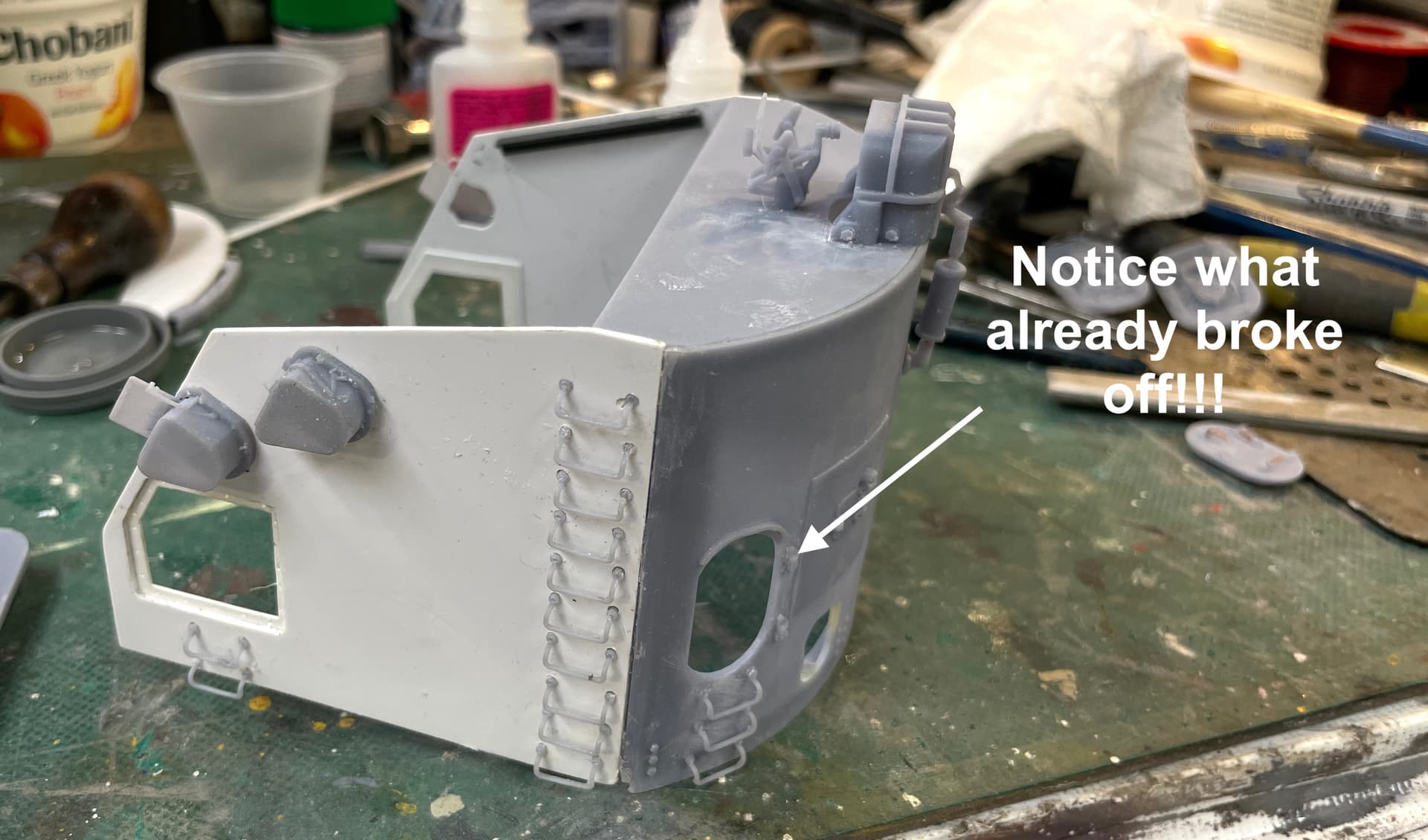
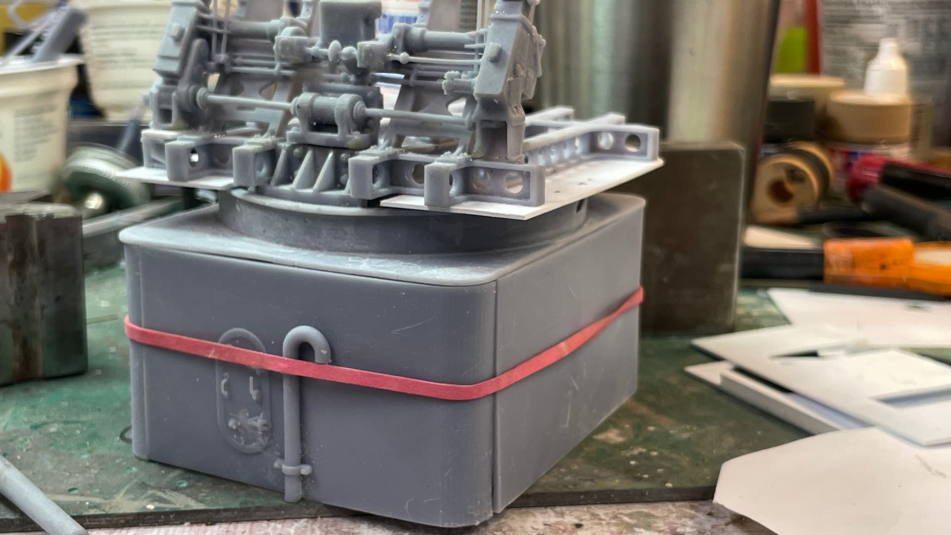
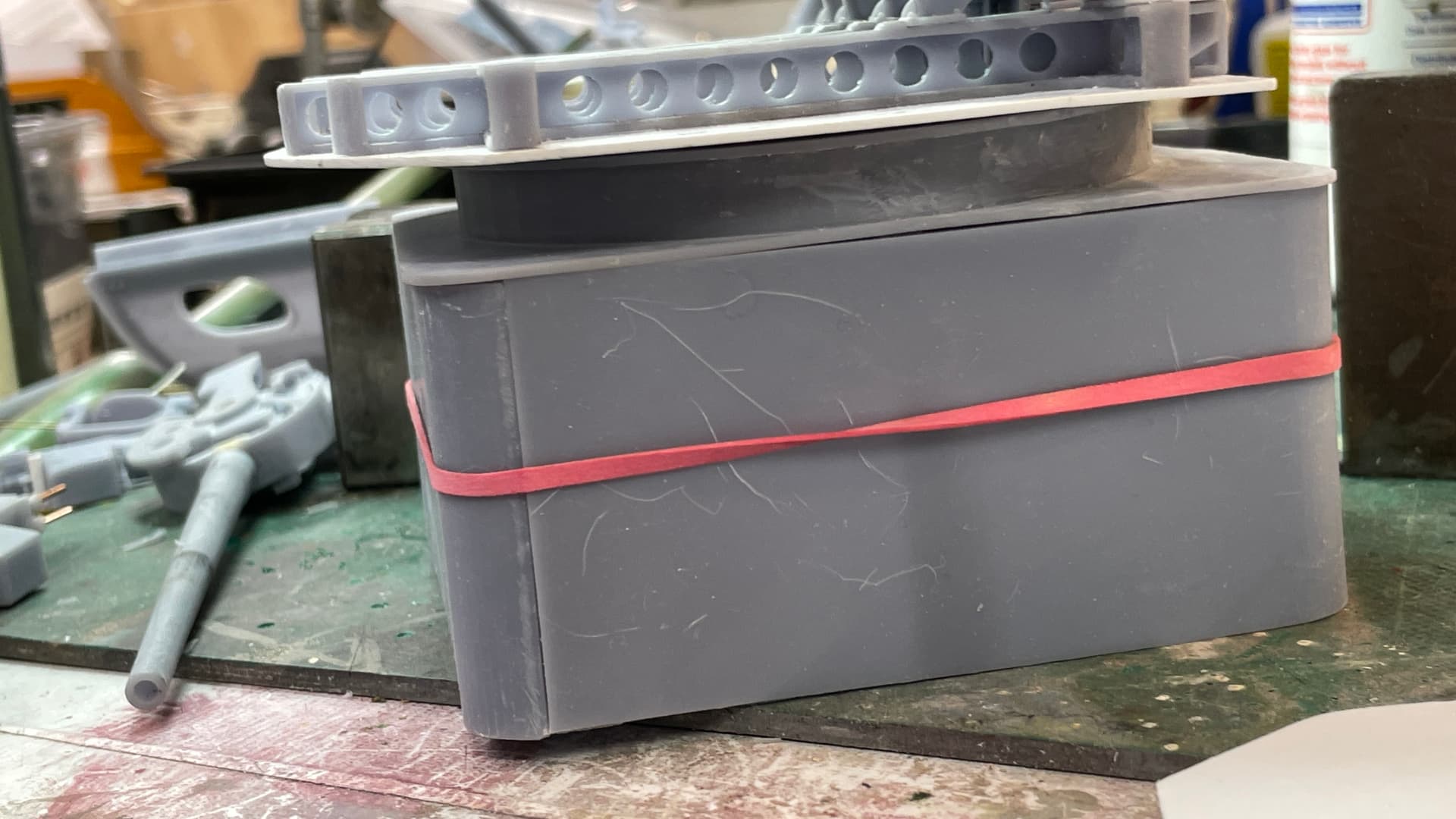
And here are several shots showing it in a test assembly.

I’m thinking that instead of cutting away some of the structure, I’m just going to leave the front wall off.

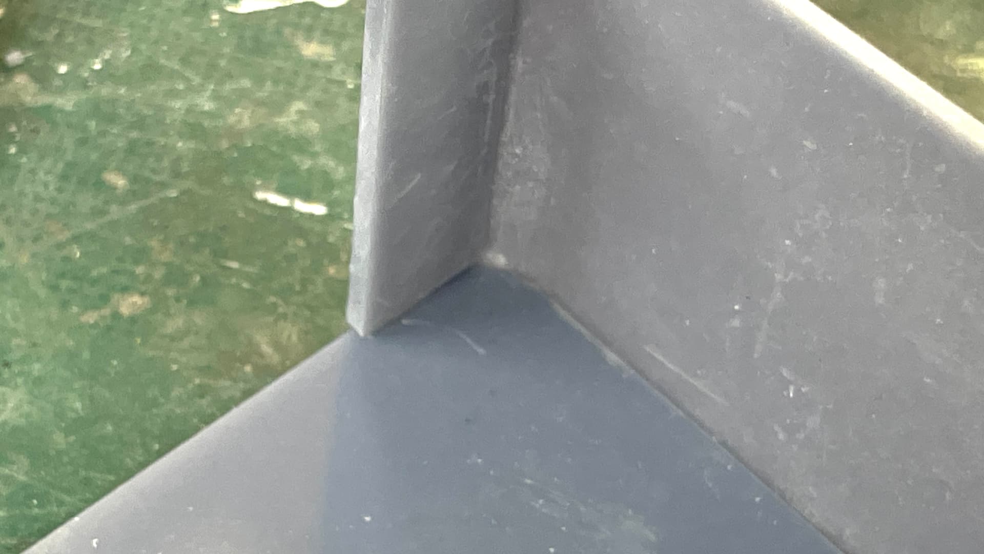
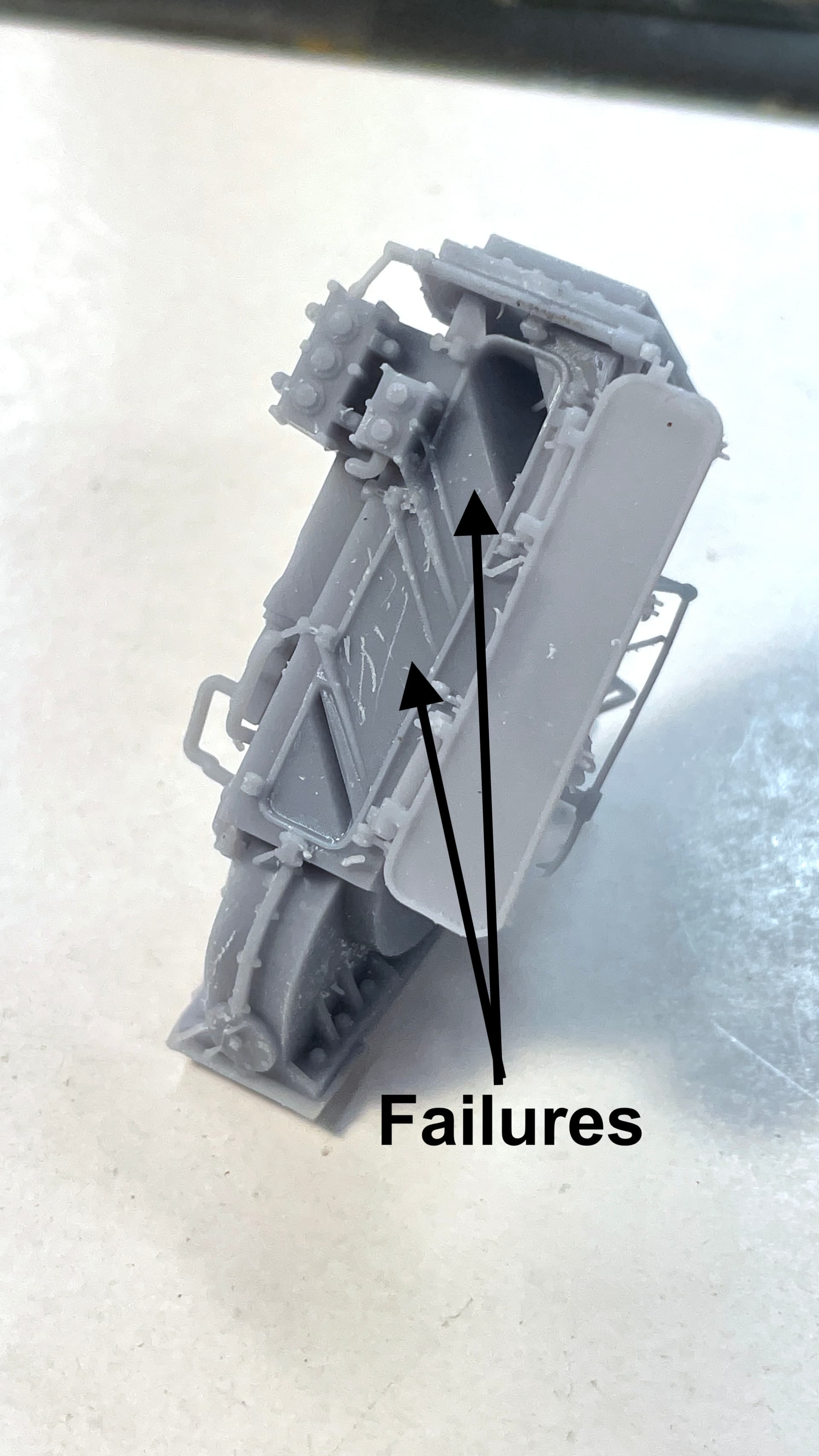
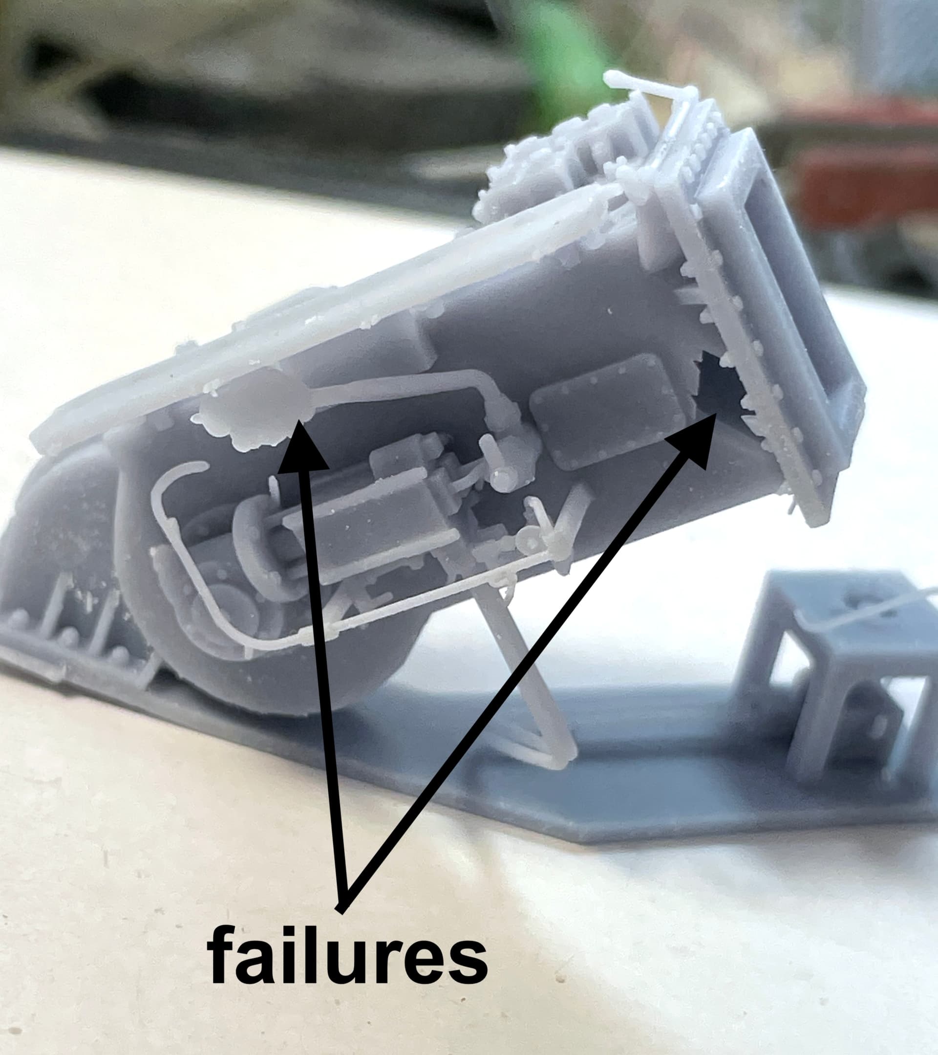
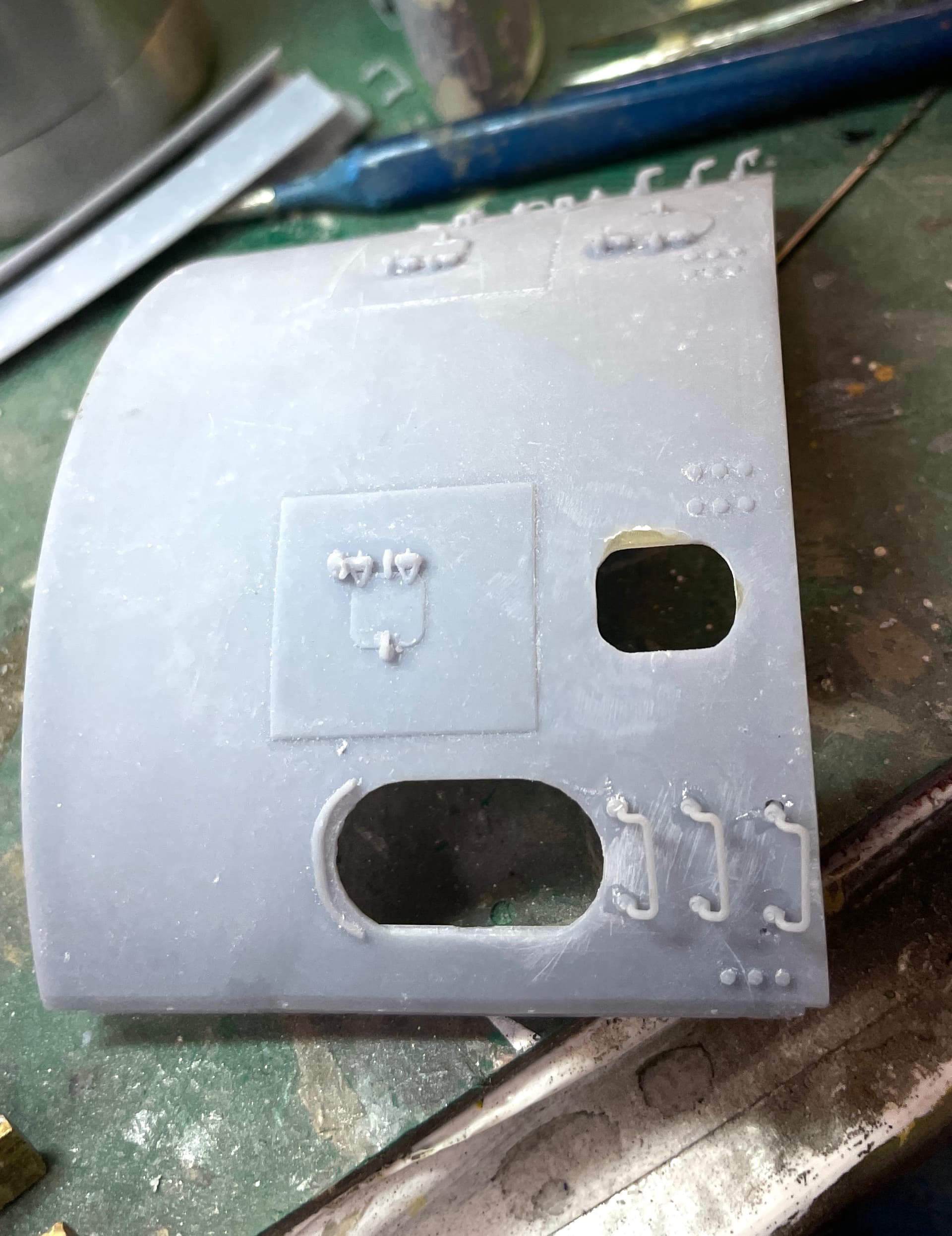
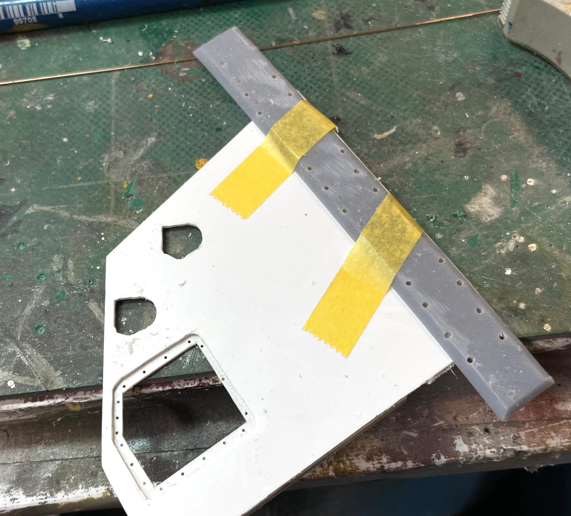
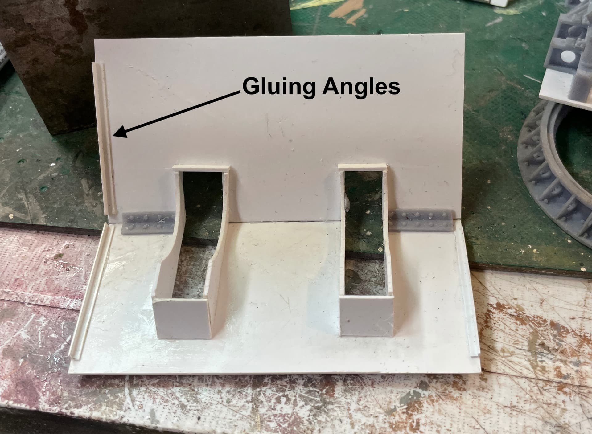
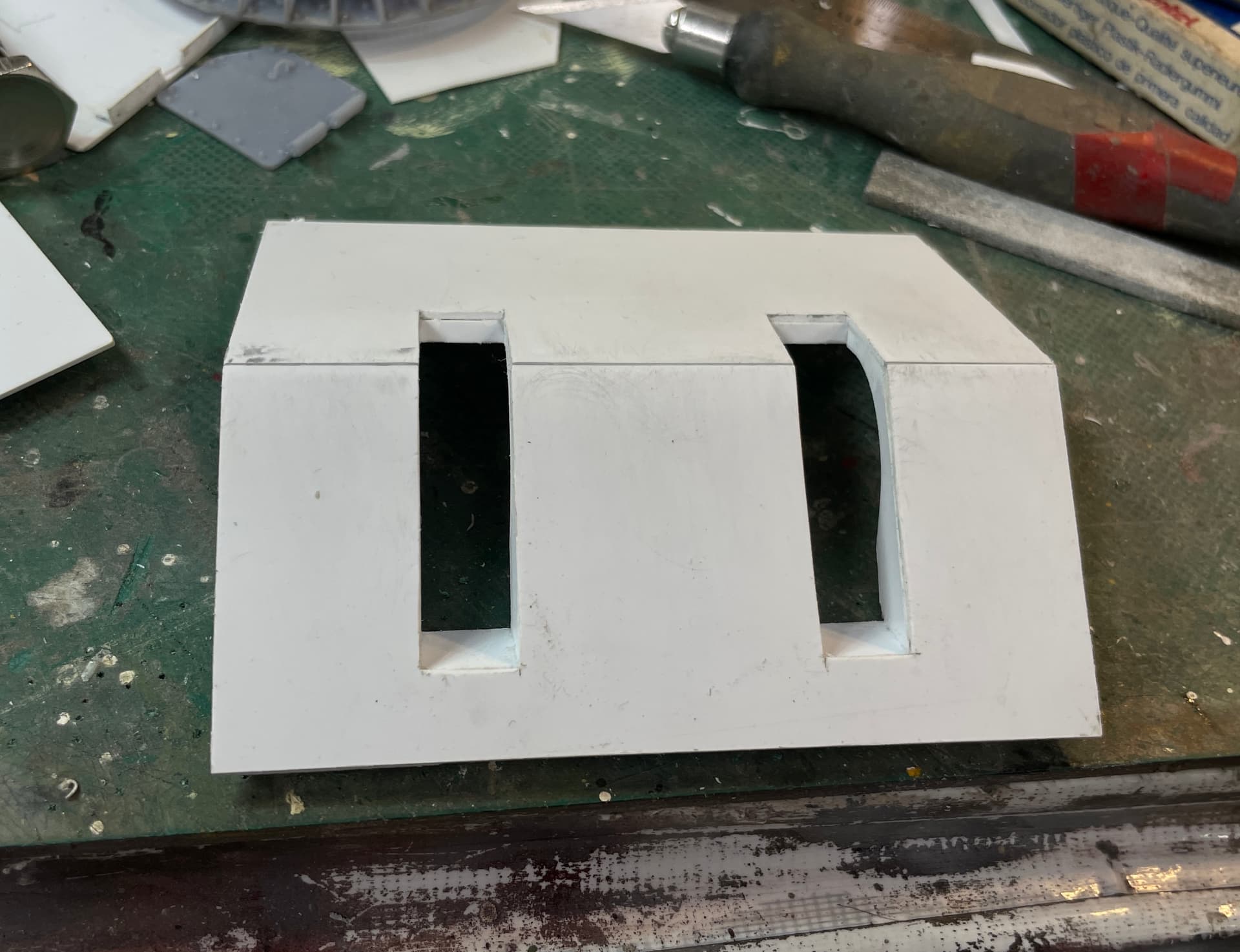
While many of these parts were in various stages of printing, cleaning and post-curing, I was getting to work on the gun house shield. I thought I was being smart by pre-installing the angle edges that would provide more gluing surface. Unfortunately, my first go was wrong. This was it.

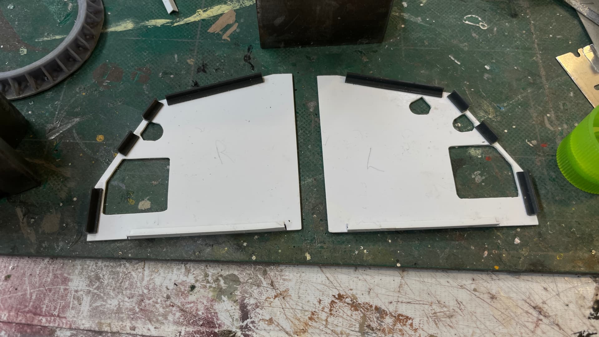
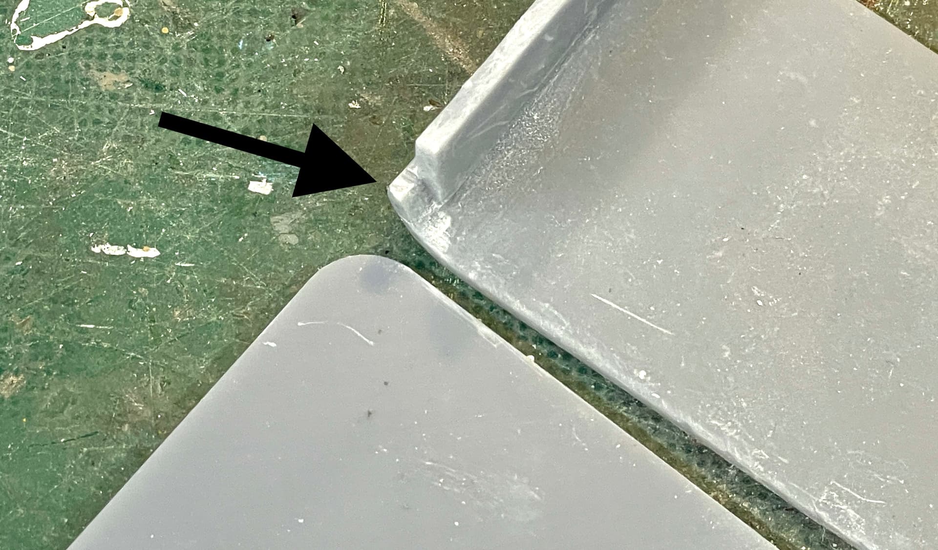
It was wrong because the upper surfaces go inside the edges of the right and left walls. However, I had them flush to the edge, not leaving the single material thickness needed for the proper joint. Happily, the ABS angle pieces, don’t weld well to styrene with normal styrene liquid cement and I was able to pop them off. The bottom edge angles DO glue flush to the bottom edge.

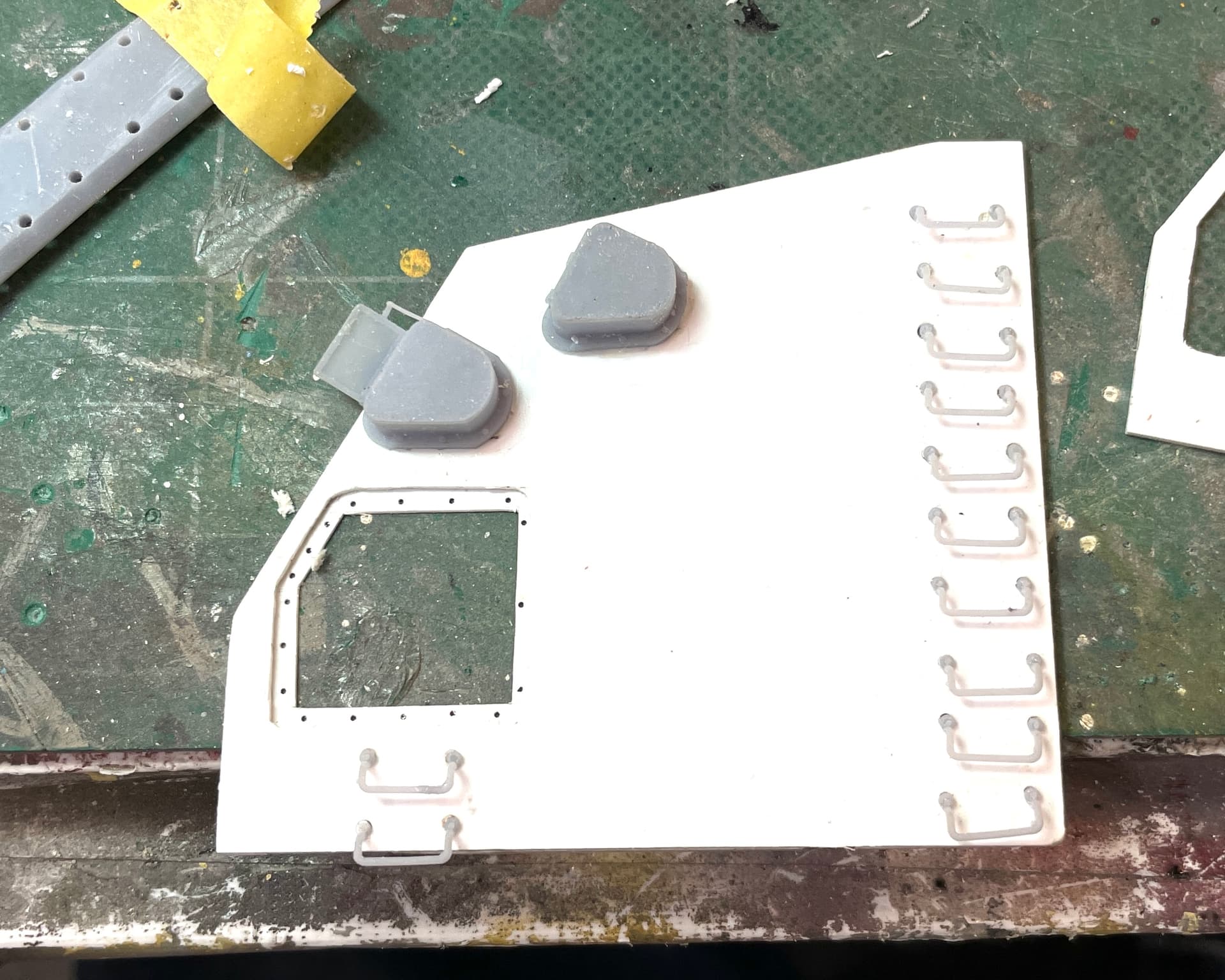
Instead of fussing with the spacing I just glued them on the roof pieces flush with their edges, which, in this cae, was the correct way to do it.

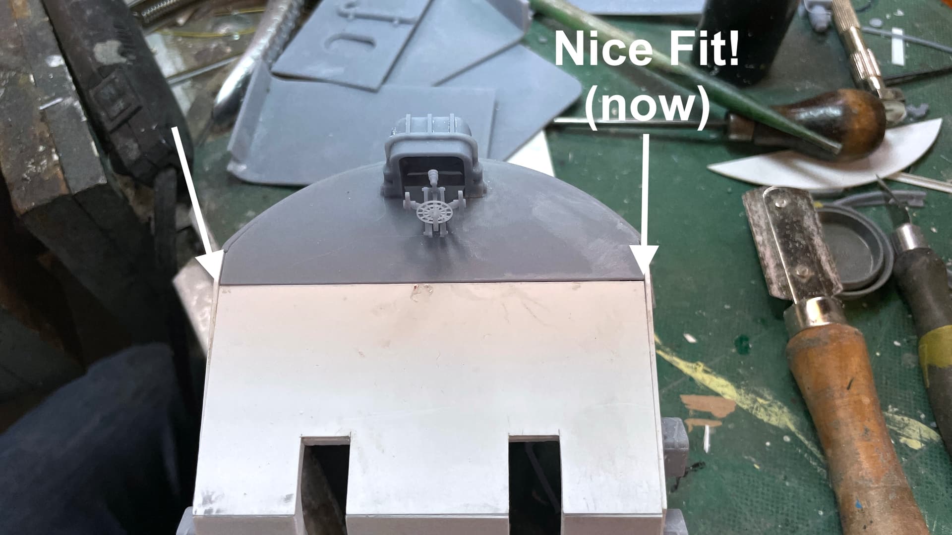
I had printed some angle pieces to hold the roof pieces at the proper angles. I also finally cut the front gun shields. These were tricky piece! There was no way to really understand their shape and how they interact with the rest of the inner structure. I made them a little longer than needed with the thought that I’d make field mods. And that’s exactly what I did.

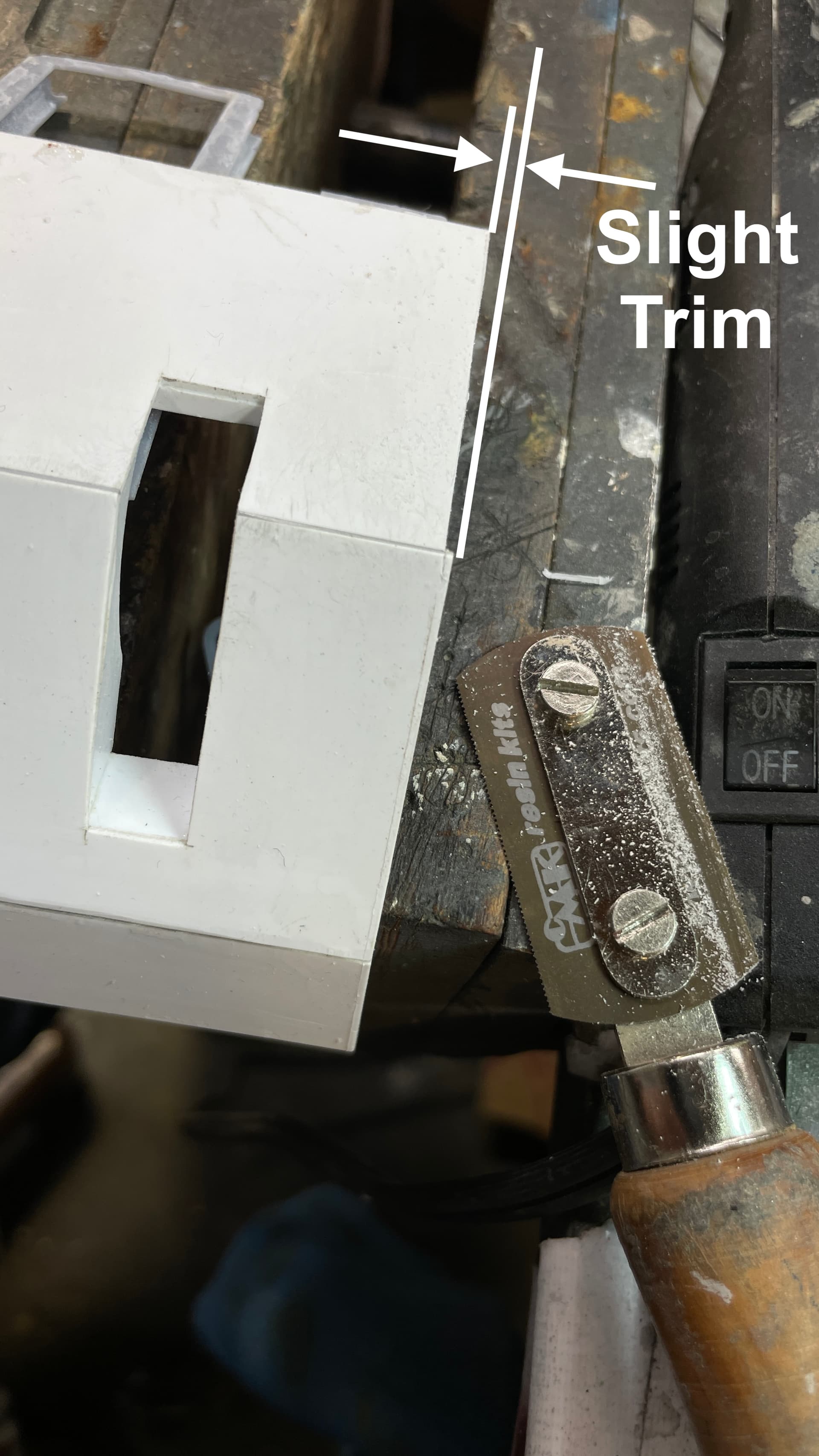
This is when I glued them to the front two angled sheets. They serve as a weather seal around the rotating gun shield and they help me join the angle pieces together. After installation the first piece I trial fit it to the gun house and found that it needed a lot of trimming. I was using liquid cement, but found it was causing the styrene to fracture. I switched to good old standby, Testor’s tube cement.

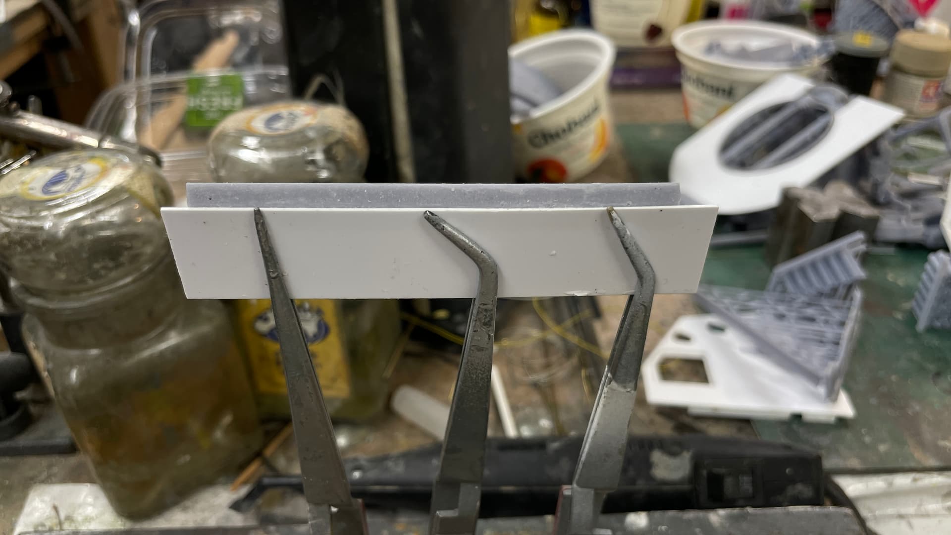
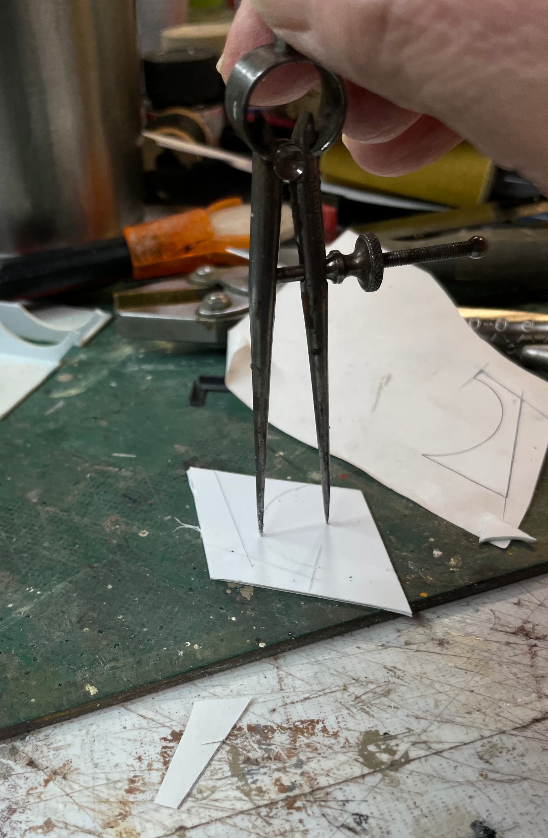
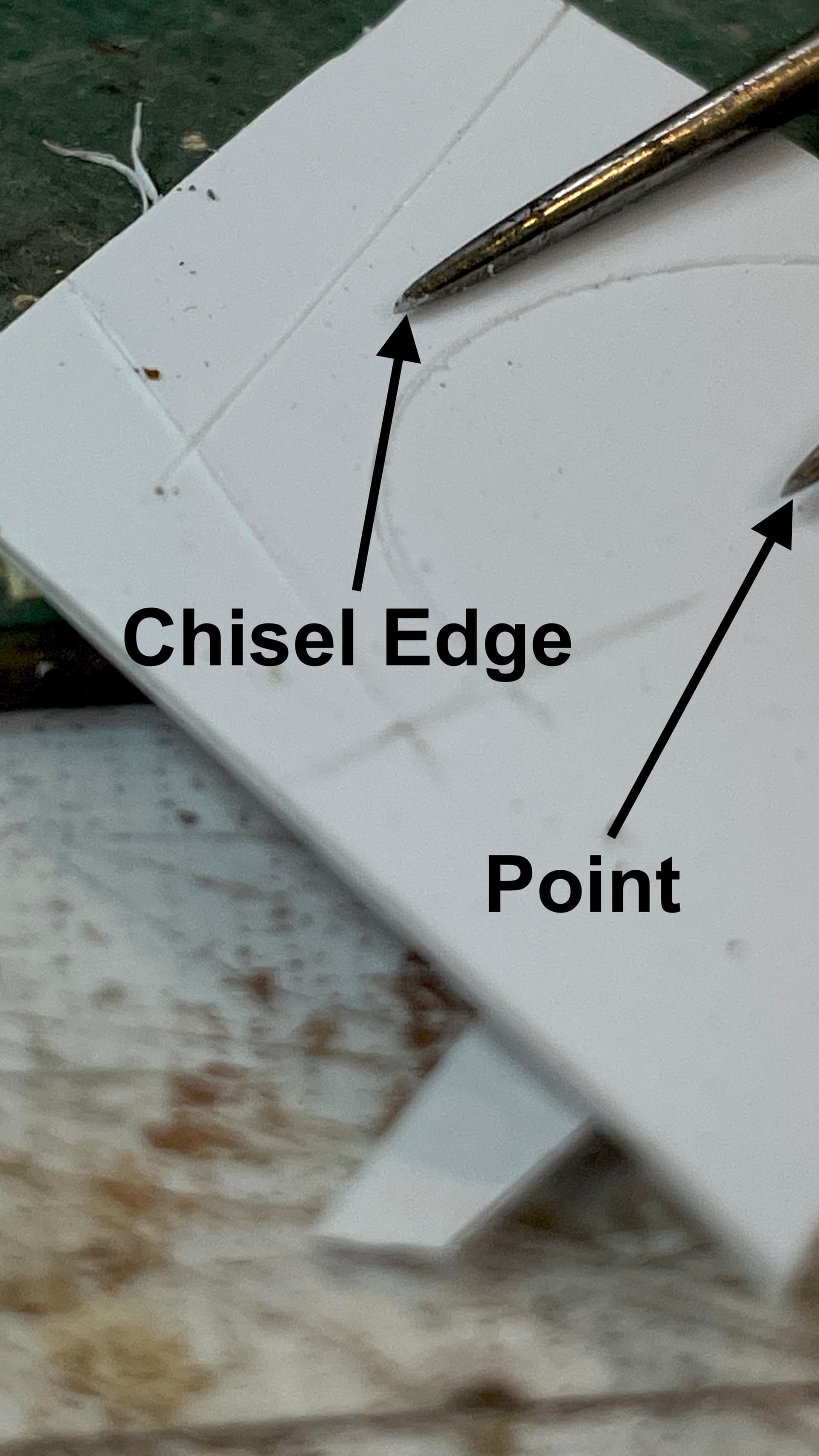
I’ve shown this in other threads, but it bears repeating. I cut circles in styrene with a specially modified machinst’s dividers. I sharpen on point to a chisel edge that’s parallel with the circular path. I can then scribe perfect circles that can be snap cut. I find it easier to spin the part and hold the dividers stationary since I can keep it at a uniform cutting angle.

This closeup shows the chisel edge.

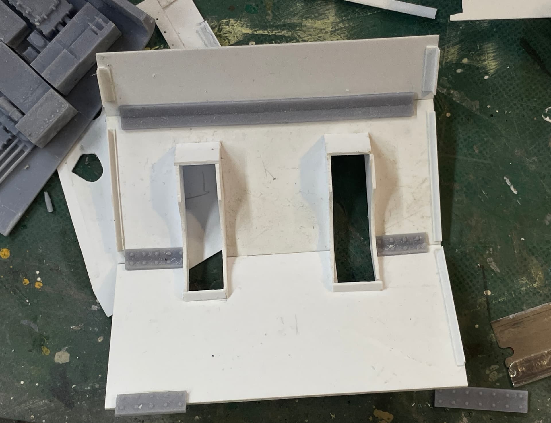
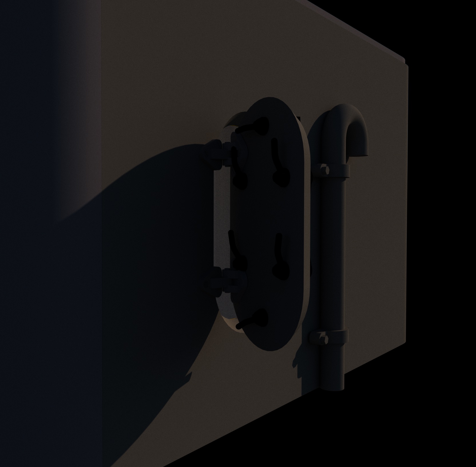
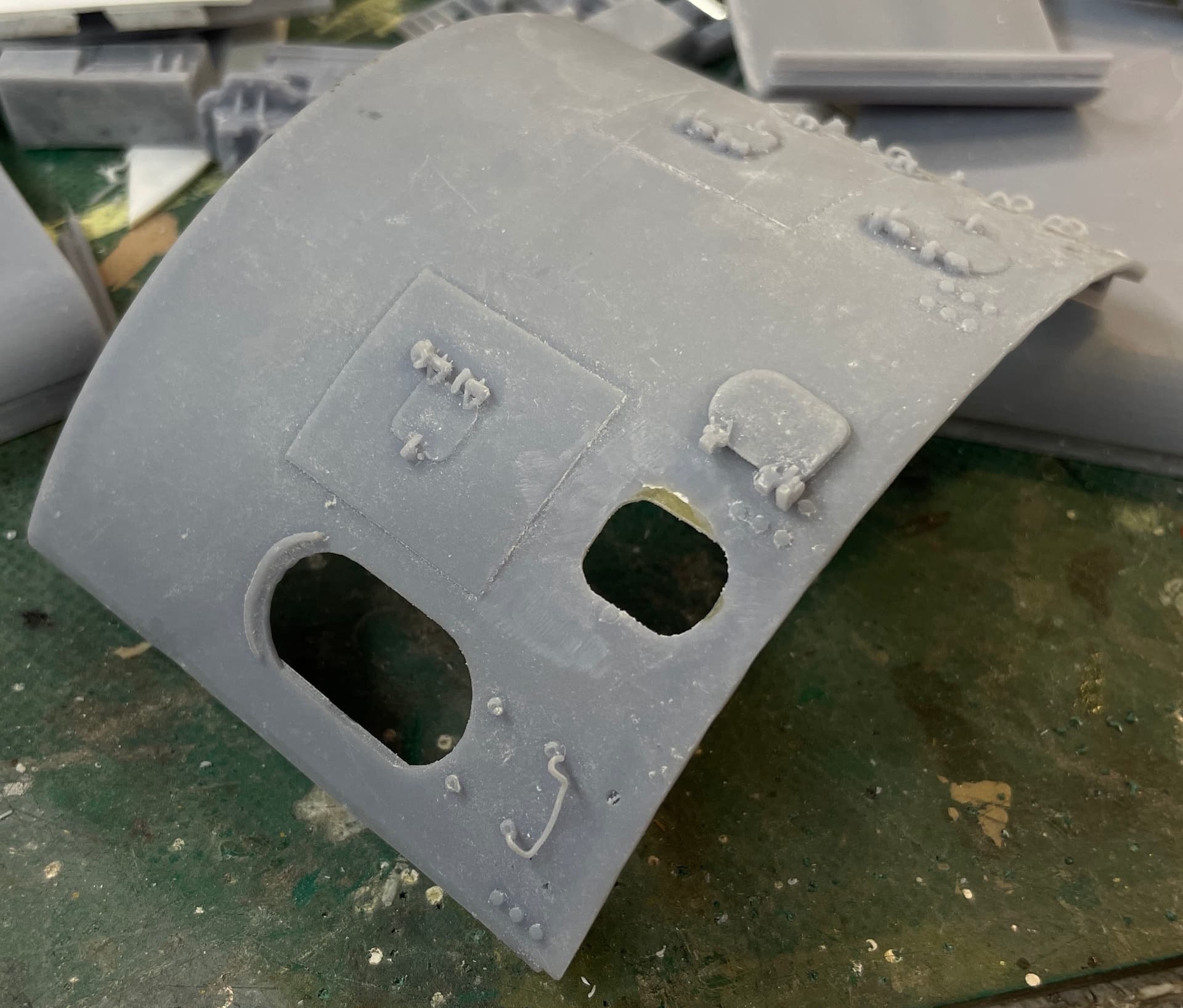
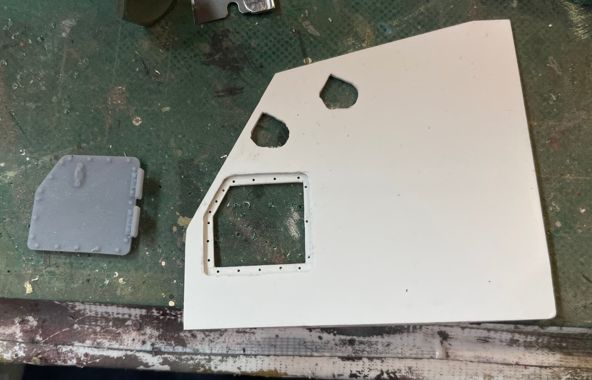
Another detail that needed work… I found that when the access doors are opened, they are swung all the way open. I had originally shaped the hinges for a 90º opening. And I wanted to have the screw holes empty and have a inner edge of the hole. I used some thin styrene sheet with 0.020" holes drilled in the matching pattern. The illusion is a good one. I’ve printed new doors with the hinges fully folded and no bolts.

The outside joint needed some filling and sanding. This was nice, normal, old-school model building job.

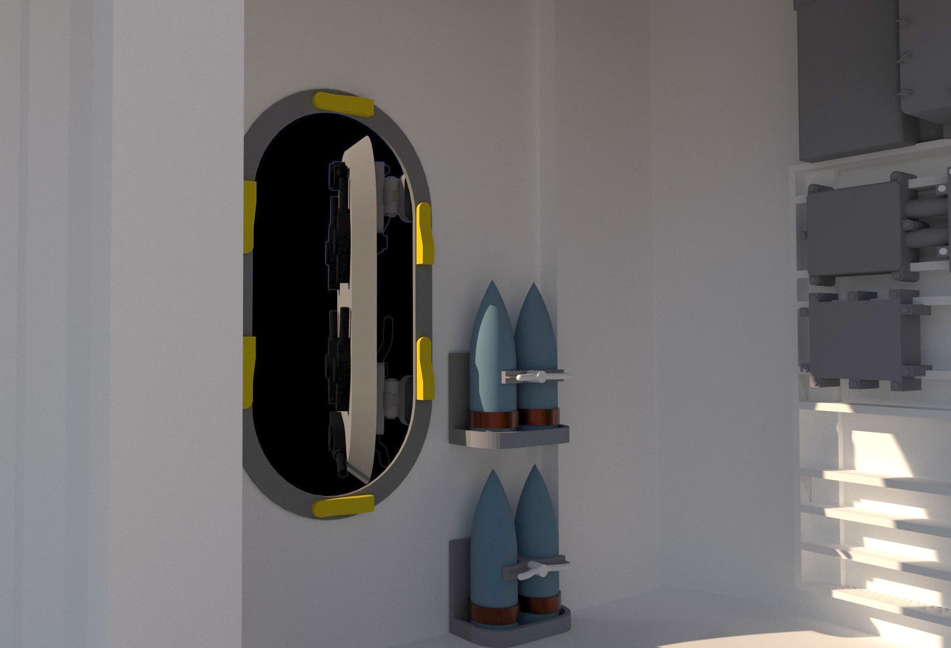
I drew and printed the last details for the gun house; the cartridge discharge chutes, and the cam brackets that sit at the back of the gun pan. With these parts everything in the gun house is printed and ready for paint and assembly.

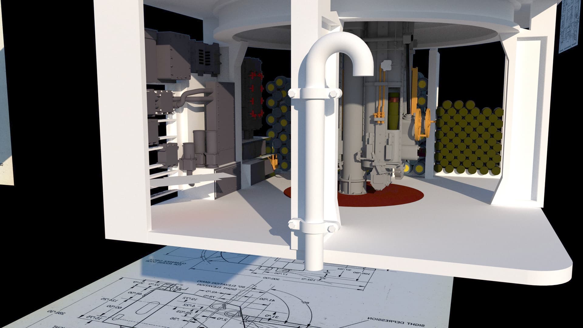
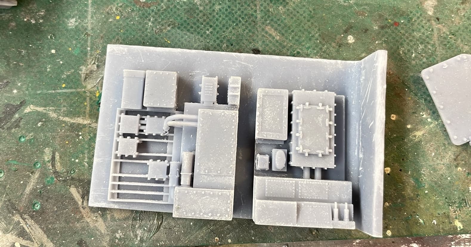
The next up was the ammo racks that line the rear wall of the UHR. After trying different methods including those offered by readers, I was able to draw and print the 80 cartridge and 20 cartridge arrays for the powder tanks, and the projectile rack. In each case there is a big chunk of plain resin so the printer didn’t have to cope with all the intersections therein.

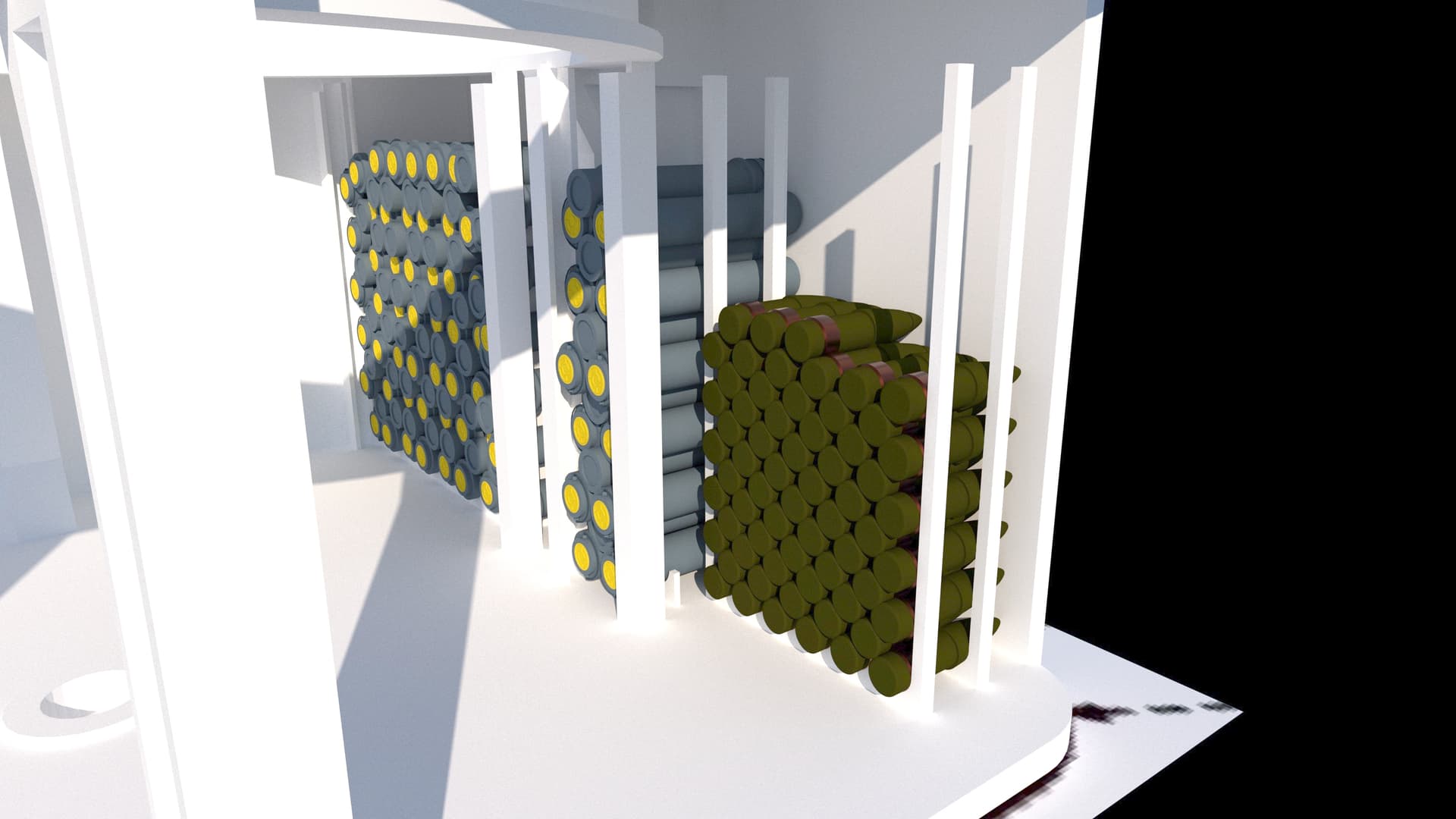
This is what all of this looked like in the slicer. I was confident that it would all print successfully.

It did print perfectly. In the cleaner now.

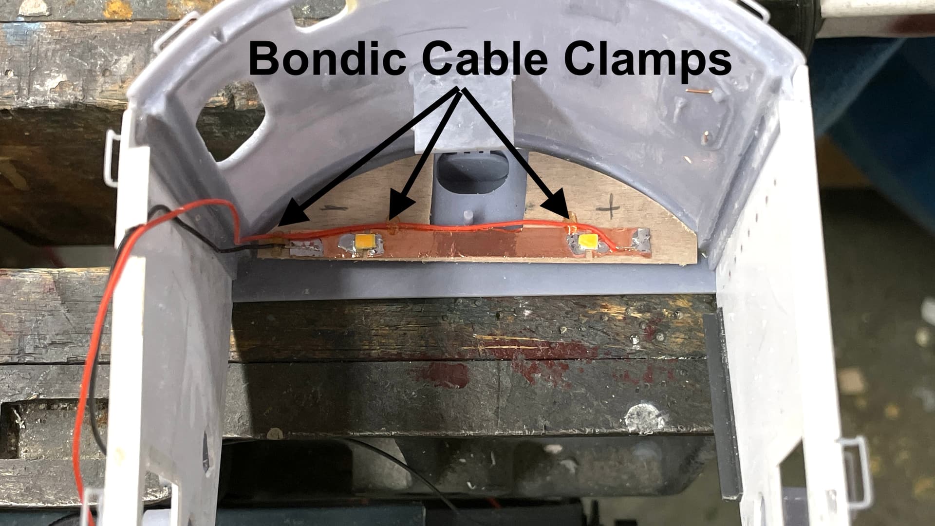
Lastly, I fit the ceiling beams into the now-constructed from glacis plates. It needed a scosh of trimming to fit. I didn’t allow for the over-scale thickness of the gun seals.

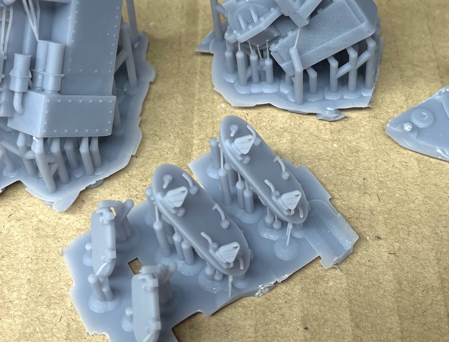
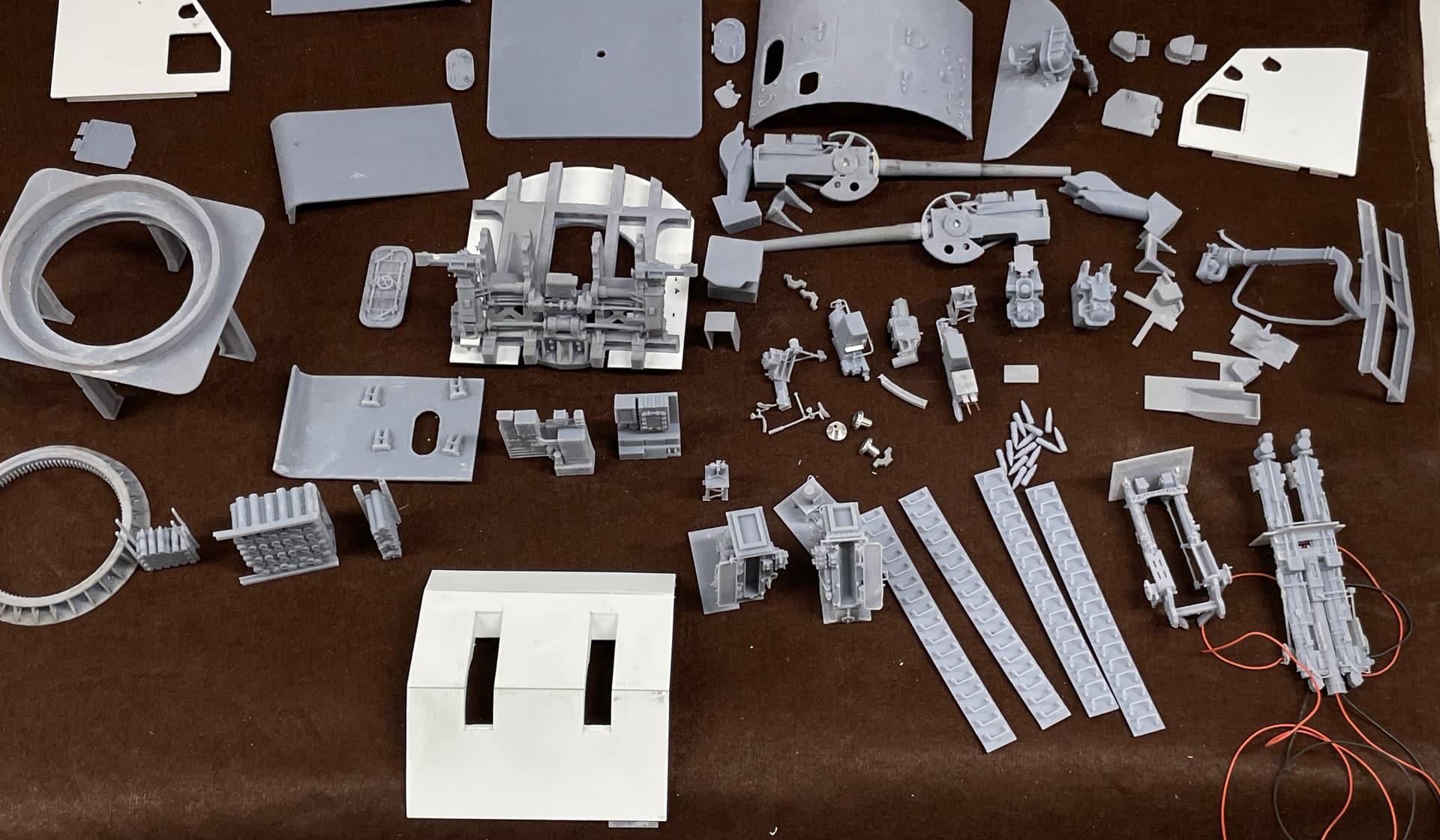
Here’re all the racks for the UHR. I print doubles of everything, I only need one of each type, but experience tells me that all kinds of things can happen before the model is finished.

Tomorrow’s Saturday, so no work in the shop on the weekends. So all have a nice weekend. Don’t do anything stupid shoveling snow, it you’re in an area where it going to hit and I’ll see y’all on Monday.

8 Likes

This is the first time I’ve stumbled on to this posting and I have to say I’m absolutely gobsmacked!!!

The amount of work required for this project is simply unbelievable. As someone who was trained as an engineer and worked for 30 years at Ford designing parts for the F-Series, I know just how much work goes into creating the IDEA of the parts needed, translating that idea into a design “drawing” which is then handed off to manufacturing to actually produce the parts. My career covered the time period when we transitioned from slide rule to computer and 2-D drawings to CAD and knowing how much having 3-D models of individual parts facilitated the ability to put individual parts into assembly position in a layout to determine clearances.

Reading through this points out just what an INCREDIBLE job it was for the ACTUAL items to have been designed and manufactured (by the THOUSANDS), back in the late 1930’s and early 40’s, when all they had were pencil and paper.

BRAVO ZULU!!!

1 Like

Sincere thanks!

When I built this one,

I thought it would be the last monster, custom build I was going to do, but the 5" system was nagging at me. While smaller in stature than the 16" system, it crammed a lot of ambiguous stuff in a small space. I had collected some reference on the 5"38 for years, but was reticent to do it because of the above reasons.

But I’ve reached a point in my modeling life, that I wanted each project to push the envelope regarding my skills and also for the hobby itself. I know of no other massively detailed 16" system anywhere and hope that this one is the same.

As the 16" project got on the ground, Ryan Syzmanski, the New Jersey curator, and I slowly began to develop a relationship. I needed his input! When the project was finished and I delivered it,

the relationship went from “a desire to build something” to “Here’s something special to display on the ship.” Now I needed him more than ever. Ryan and I now communicate almost daily. We’ve become friends and if I need specific images taken in specific ways he delivers quickly. it’s making the job possible… not easy… just possible.

Lastly, without being skilled in SketchUp (constantly learning new techniques) and 3D resin printing (constantly learning new techniques), I wouldn’t even have attempted it.

And like you, it’s hard to imagine the creativity, skills and shear intent that enabled people to design, build and field these machines without the digital aids we have today. The 5" 38 first appeared on a destroyer in 1934. By the end of WW2, they were in place on every type of ship in the Navy, in many varieties. The mounts, shields and fire control changed, but the gun itself did not change. It was essentially perfect. I aliken it to the Fender Stratocaster, designed by Leo Fender in 1954 and remaining essentially unchanged since then. Another creation that fits this description is the Eames Lounge Chair and Ottoman that was designed by Charles and Raye Eames in the mid 50s for the Herman Miller Furniture Company. It’s still produced today and found in many art museums all over the planet. You can find them in movies, TV shows and people’s houses all the time. I’m sitting on one writing all this crap.

With this project coming along nicely, I’m left with the dilemma of what to do for an encore. If each project has to be more comprehensive than the last, what should/could it be? I’ve actually been entertaining modeling the engine room. Hmmmm…. I like modeling spaces where visitors can’t get to, or even when they’re there, can’t comprehend the totality. The 5"38 fits this criterion. Even when you’re actually in the turret, it’s hard to figure out what you’re looking at.

5 Likes

Great post! While NOWHERE nearly as comprehensive and detailed as your 5" is, I also am lucky enough to have found a place to display one of my models and in a place where it adds something to the location. I detailed the interior of a Ford Built B-24H which now is on display at the Yankee Air Force Museum (only about 6 miles from where I live) located at the Willow Run Airport where Henry Ford proved you COULD build aircraft on a moving assembly line and (finally) wound up producing more B-24s than any other location. Ironically there IS no actual B-24 there and with the help of the staff there I was able to find drawings that helped complete the project. They’re restoring a tail section, but at least this way they can have a representation of how complex and crowded those things were.

I’ve posted the link below from the old Forum.

And while I share your sentiment about Leo Fender creating a master piece, as a bass player, I’d say that the designs for the creation of the Precision (which invented the electric bass guitar) and the Jazz are right up there!

2 Likes

Whenever I get a little full of myself, I see a model like you constructed and it brings me back to earth. That B-24 is clearly worthy of a museum and I’m glad it’s in one. I’m working in the same scale and could, if I were so inclined, to go even further with all of the tubing and wiring that this model could support. I don’t think I’ll go there, but what you have done clearly shows what’s possibe. Thanks for sharing it with me.

While we’re still talking music… Leo Fender never learned to play guitar. His forte was amp design and the electronics. The inventor of the Hammond Organ didn’t play organ either. They’re very different skills sets. I forgot about the Precision Bass when discussing the Strat. Same basic body design.

Short session, but productive. The circuit panels that line the side wall of the Upper Handling Room were fun to draw and even more fun to see how nice the prints came out. The printer has been effectively flawless. Even the FEP with the new Elegoo formulation has been working for months. It’s very forgiving. If there’s anything sticking to it, you pop it off and you’re back in business. I used to be happy to get a couple of weeks without wrecking the film. Now I go so long I forget when I last did it.

Here’s a view of the actual wall in the Upper Handling Room. The projectile dredger hoist upper is in the view. As you can see, I can’t model it becuase I have no information about the lower parts of it.

As you can also see, part of the view is obscured by the open projectile dredge hoist lid. There’s a lot of cabling coming out of the tops of the panels. I may or may not add that with wire during the build. It will be hard to see.

Here’s my interpretation of the wall.


And here is the printed part. First sitting on the blank wall, and then sitting with the ring frame support separating the two parts.


It ain’t perfect, but it supports the illusion. I had absolutely no definable dimensions on any of this equipment, so it’s all and educated guess.

I glued in the angle brace for the lower front to glacis plate joint.

I then glued the front plate to the rest of the shield assembly. I also added some more angle brackets to support future assembly. All these resin to styrene joints are with thin/med CA with accelerator applied first.

The resultant joint needs filler and will be done later.

Lastly, I finished drilling out the open bolt holes on the now-open acress panel. I bought a whole bunch of 0.022" caribde drills from Drill Bills Unlimited. In this case I bought a shorter length and re-sharpened to save some money. I don’t know what it is, but I was breaking them light crazy. I used four drills opening up these tiny holes. At a $1.50 each, this adds up to real money pretty fast for just one part.

Tomorrow my wife goes through the first of four chemotherapy sessions. She’ll have one every three weeks ending in mid-March, so I may or may not be in the shop tomorrow. She’s supposed to be done at 1:30 and I’m going to stay with her the entire time. I’m bringing my laptop so more design work could still get done. I can’t do much more with the UHR until Ryan gets me the dredger hoist images I need.

6 Likes

Hello Builder! Reporting on a new forum - I already like it here! Good luck with your turret and see you around!
Paweł

Found you!

Wecome back guys. You’re making my life easier and the thread remains the same.

I’ve been getting more quality drawing time since I’m not in the shop. I helping my wife recover from her first chemo session. I know why people don’t look favorably towards chemo. It beats the heck out of you!

With Ryans new images, I was finally able to draw the access door correctly. It boggles my and Ryan’s mind that there are so many types and sizes of doors on the ship. I originally assumed that the handling room access door was the same as the access door to the gun house and drew it that way. I was wrong. As you can see it has 6 dogs, not three. It’s also tapered for explosion resistant like that of the armored pilot house, although that one is 18" thick!


The inside flange has brass cams that bind against the dogs sealing the door. I’m going to model this door open. I’m going to get some of the new Real Metal Foil gold foil to simulate any brass surfaces in this model with real reflective metal.

Drawing the upper handling room hoist structures took over a day and half. I originally had it a bit too long. Ryan came through with 18 images of the hoists (upper and lower), even including a tape measure in many of the shots. It was difficult reading some of the numbers, but I was able to muddle through. There aren’t many square angles. There are lots of fillets, curve edges, things lying at weird angles and mechanisms that needed to engage with one another. SketchUp is not particularly happy working with shapes such as these.

I drew it so the lid can be printed open or closed. I was thinking of displaying each unit in one of two configurations, but this woud prevent me from having either a projectile or powder tank peeking out of the top. I’ll print enough so I can make a field decision.

Here’s a nice rendering showing the color scheme. Any surface that can be in direct contact with either projectiles or powder cannisters is made of brass to eliminate spark hazards.

Here are the two hoists in place in the handling room.

I’m going to print this tomorrow or Thursday. The lower hoist is significantly more complicated than this one. It is the power section so there’s lots of hydraulics, piping and odds and ends besides the actual hoist mechanisms.

This is what I’m talking about…


I am also going to reprint some other parts needed for the magazines, especially the scuttle doors. These were printed with the old settings and aren’t up to the quality I’m now getting. I’m going to review all the previously printed parts and reprint any that compromise the quality I’m trying to hit.

7 Likes

While nursing my wife and her miserable experience with Chemo, I’ve been drawing away and did some 3D printing. I printed the upper hoists while I’m still working with Ryan on getting as much detail as possible about the lower ones and their enigmatic hoist trunks. I printed open hatches, and another attempt at the one cicuit panel wall. The first one had some annoying drawing/printing errors that I didn’t need to keep. Lastly, I printed a new door wall with the tapered opening and improved locking pads. This one came out 1/16" shorter than the other wall. I don’t know why, unless the entire handling room height changed in one of my iterations of the shape. I’ll reprint a correct one. I felt that was a more elegant solution than grafting on a 1/16" strip.

As before, the printer is working like dynamite. Whateve I want, no matter how tiny, it’s reprouducing. This is how I’m putting them on the machine. I have all their rafts touching so the entire group pops off the Wham-Bam sprint plate as a single part. Makes it easier to clean and fish the parts out of the alcohol baths. I then put the who deal under the post-cure lights and then trim and finish.

Notice how thin the fine support connectors are. They look like they shouldn’t work, but they do and they’re small enough to not damage tiny details during their removal. As fine as the supports are, they aren’t breaking during the print. They break when I want to remove them. Before I recalibrating, I was losing the small supports all the time.

In this view you can see how smooth the walls are. I’m printing at 0.04mm layer height and it shows no layer lines. It’s what many non-3D printing folks worry about with this technology.

Here are the cleaned, but not perfectly… hoists. The powder hoist is in the open position with a powder cartridge ready to be removed and the projectile hoist is in the closed position. You can actually make out the tiny screw clampos that hold down the lid when stowed.

Here’s a vignette with the projectile hoist in relation to the circuit box wall.

Lastly, here are the new doors. The big one is for the handling room and the little one is the cartridge chute, one of which I’m going to pose open. The hinge attachment points are very fragile and I’m trying to visualize how to attach (and when).

One of my dear friends and astoundingly amazing model builders, Chris Bowling, explained how to spray paint outside in colder weather by heating the rattle can paint in a bowl of hot water for about 5 - 10 minutes to warm it. It works well. I may have to resort to this since all these parts need priming before color coats and it’s been too cold outside to do it. I don’t paint solvent-based paints in the shop and don’t (yet) have a spray booth. I’m vascilating between wanting to splurg on a 40w solid-state laser cutter or a decent spray booth. Actually, you need positive venting of the laser cutter since they produce some bad fumes too.

8 Likes

I do this regardless of the outside temperature or paint brand when I use a rattle can.

2 Likes

Just did a binge catch up…

Firstly… I hope your wife has a speedy recovery as she goes through the treatment…

Secondly… WOW… Another amazing in depth and super detailed build… Looks amazing… :+1:

3 Likes

Thank you both! Today’s she’s having a pretty good day, but the hair is starting to leave. Well… at least it means that the chemo is working.

I drew another little detail. This is the manual sight sitting on the gun house roof that’s used by the gun captain occasionally. It’s really old-school, using some wheels and metal cables to transmitt the optical position selected by the captain to manual readouts next to the trainer’s and pointer’s stations. It would be the sight of last resort if all the power was out. It’s a very fragile assembly so I had to beef it up a lot so it would hold together as a printed part. Ideally, it would be nice to do it in photo-etch, but I don’t have that capability, and don’t want it due to the nature of the chemistry you need.

To increase the odds that it will hold together I chose to print this, along with the captain’s hood with the rear gun house roof piece. I had originally made the roof out of styrene, but didn’t like how the hatch hole came out so re-doing was in order anyway. It’s printing now and will be done in about an hour.

I don’t think I’ll be daft enough to actually attempt to wire up the mechanism in the gun house ceiling. It would be hard to view and even harder to build.

I’ll display this print tomorrow.

5 Likes

Here’s how it turned out.

It’s slightly oversized in my estimation, but at least a person can make out all of the geometry. The roof is not glued to the back…. it’s just sitting there for the picture. Printing the parts directly from the drawing that created them helps insure that the fit is essentially… perfect.

I still had a error in the hood assembly that I forgot to correct. The lower clevis on the counter-balance cylinder wasn’t actually integral with the cylinder and when the support was removed it just fell off. Some careful drilling with a 0.022" carbide drill and wire of the same diameter fixed the problem permanently.

I also gave up on trying to open up the cartridge hatch on the drawing… causing way too much agita. I just cut it out old-school. My cut went a little wide, but was fixed with some Bondic. Bondic, being the same chemistry as the UV, makes a permanent and strong bond with the resin. It sands the same, and when painted, is invisible. To hold the little door hinges to the wall I will also pin them. This time with something even finer (0.012")

All these added doors will be very easy to break off during handling. I’m still fretting over just when to install them.

7 Likes

Here’s some more eye candy. I’ve got the two lower hoists almost finalized. Still waiting on a couple more images from Ryan to get some of the piping detail more accurate. Right now a lot of it is my imagination running wild. Getting the angles of departure for the ammo trunks that go up to the the Upper Handling Room was difficult and could be wrong. I took the angle directly from the pictures taken by Ryan of the sides of the more vertical one. The tilted one, is more of a guess. I’ve asked Ryan for a direct side shot of both sides so I could confirm the angularity and the piping details.

I think they’re too tall. Ryan measured them at 6 feet or so, but with the base I made it seems to high.

These units with all their detailed glory with sit on the port side wall of the magazine and have their backs to the viewing public in the way that I’ve envisioned the display. Ryan I are discusing how else to display it so both front and back details will be viewable. One possibility is having the back as a mirror. Another would be displaying it where all sides can be viewed. To be decided.

Next up are the hydraulic pumps on steel stands which are much more pedestrian that these things were… and… they’re both the same. Only diffirence is where they lie vis a vis that hoist themselves.

6 Likes

To nestle Upper Handling Room’s floor to the sides I had to do some minor surgery to remove some of the corner glue strips from the walls as shown in these images. The choice was to trim the floor of the wall. I Chose the wall.


The walls now fit nicely.

Printing the hoists is halfway done. It would be “all the way” done, except the slanted one had some fatal print errors that I traced back to fatal drawing errors. When I went about removing some internal faces that were making the part more complicated, I also eliminated some of the external details and didn’t realize this until I tried printing it.


The little lugs that protrude from the door are really, REALLY, tiny! And they printed just about perfectly. I need to be careful in future handling and painting so I don’t remove them.

The slanted hoist wasn’t so lucky. One of the critical side details didn’t print at all because the part in the drawing wasn’t connected to the main surface. Also the entire hoist chamber filled with resin, whereas it did not do this on the vertical one. I did some major internal surgery to attempt to preventing it happening again. I will attempt to print it again tonight.


This is interesting (at least to me). I did a wire pass-through test to see if the wireway in the upper projectile hoist was sufficiently large to pass the two-lead power that will feed the gun house lighting. It worked! BTW: This is the same place that the wiring goes through on the 1:1 mount.

My old friend, Bryant Mitchell, (the fella who’s building the wood base for this and the big gun models, suggested making an electronic “tour guide” of the model showing closeups of those details that won’t be available to the viewer. This idea has immense possibility. Having the model so people can walk around it makes it difficult to get power for the lighting. Having against a wall blocks viewing anything that’s facing rearward. Having a the back plane of the case being a mirror could work, but doubles the viewing distance. When I brought this idea to Ryan he immediately thought of those digital picture frames. I have to find out more about what they need, but making the photoplay wouldn’t be a problem for me. I could caption each frame describing what they’re seeing. The images would only be of the model and maybe some exterior shots of the guns on the New Jersey. It’s great to have more than my mind on this project.

5 Likes

Took two tries to get the angled hoist to print properly AND fix the entire geometry. Ryan sent new images which showed clearly that my original slant angle was too steep. Since I was having printing problems with the main body, which I couldn’t figure out, redrawing it solved that problem. I did have a couple of minor breakages with the print, but by printing them two at a time, I was able to cannabalize off the lesser of the two and fix the good one.

First of all, here’s what’s printed and completed so far. Imagine how many pieces would be on the table if it was a conventional styrene kit…

This was the hoist as it first came off the printer and cleaned up. The very fine piping—which was a crap shoot from the get go—did print pretty well, but failed during cleanup. With very small amounts of Bondic I was able to reconnect some, but for two of them I had to cut the same intact pipes off the other one and graft it to this one. The results were basically perfect.

And here are the results. I had the same problem with this one as the other ones: the hydraulic motor were missing (probably stuck to the FEP). I thought I had reinforced the motor connections in this drawing, but it still came off. So I just found one of the rejects and using Bondic, put it back on.

A couple of the tiny lid clamps got broken, but they are beyond may attention (or anyone else’s) and I’m not worried about it.

Painting these will be fun… no… seriously… I like painting these things.

These were some of the images sent by Ryan that helped nail down some critical details.

The weather is cooperating this week, and my wife, after some adjustments, is tolerating her Chemo treatments well, so I may be able to get outside and prime paint all of the work completed so far. I have to get serious about the magazine itself, and how to represent all the intervening decks in such a way to not over-complicate the display, but convey the geometry. I was originally going to craft some of the “egg-crate” structure, but now I’m thinking of 3D printing it. Could allow for some better detailing.

6 Likes

I keep being amazed at the level of intricate and fragile looking 3D printed parts … some look like being breathed on heavy would break them … Great work and skill

2 Likes

Thanks! It’s fragile, but suprisingly tough. Mixing the flexible resin with the standard helps in that regard. That said, if I get careless in painting or handling (or dropping them) they will break!

Thought I was going to paint today. It was almost 60°, but I got involved in a lot of prep work prior to paint. Things like ladder rungs open and closed hatches needed to be in place before paint so I wouldn’t screw anything up after painting.

I started by finishing up the curved rear mount wall. I removed the printed-on rungs, which were either missing or very beaten up. I made a drill jig out of the base used to support the print. There were three on each side that needed adding. I pilot drilled with a tiny one, and then opened the holes up with a #55 drill. CA plus hardener holds them in place.

Then I had to decide “to add the door or not add the door”… that is the question. I chose to add, even though this makes this part much more fragile. If I didn’t add it, I would have risked really messing up the finish. I tried first to glue it with Bondic, but Bondic’s downfall is the UV curing light must reach ALL of the resin. No light, no cure! Since the hinge plates were opaque, the Bondic wasn’t working. I resorted to med CA with accelerator.

Before applying I had to replace all the broken off door dog handles with 0.020" phos-bronze wire. I had to put handles on the movable and fixed doors and the rear of the fixed door, which may or may not be visible when complete.

And with the closed door finished.

It’s not quite done yet. i still have The mount sides needed lots of foot rungs.

It was here where the drill jig really worked. When I drew the parts, I spaced them at the correct spacing for the project. After clipping off the parts, I drilled the holes at the junction spots.

I also added the telescope hoods. I’m having the pointer’s hood in the open position and the sight checker’s in closed. The sight checker only did his job during training actions.

There’s an open door in this wall also, but gluing it in place now would block being able to paint behind it. That’s going to have to wait till the paint is on.

6 Likes

I was going to try and paint outside again today, but there was way too much wind, and I still had a lot to do in preparing the parts for paint. Again, I had to make a decision about what got glued before paint. And I chose to build up as much of the gun house as possible. It would be very hard to finish and fill joints if it was all painted, besides the difficulty of making a clean joint. Before the roof can go on I had to glue in the upper framing. Instead of using CA I chose to use Gorilla Glue construction adhesive. I wanted something that was multi-material and had some decent working time to position the part. It takes 24 hours to totally cure.

I did get the port side wall finished with all its rungs and made the faux backing piece with the bolt holes (like the other side) so I can pose that side’s access hatch open as well as the starboard side.

While this cures (over night) I first glued the rear roof to the curved back. Here I used Bondic since I was gluing resin to resin and it looks like a weld bead when it was applied.

I realized that there was a problem putting in all those ladder rungs. Any pressure I put on the walls during the gluing created a wonderful opportunity to break them. I didn’t! But I did break off that door which I was sure that I would. I hate being right! I’m leaving it off and will re-attach with wire reinforcement. Any thoughts of attaching the little cartridge chute door are now dispelled. That will also wait until further along.

If I can get the walls all built, I will probably be able to paint tomorrow. Maybe… I have a urology appointment. My PSA took a jump and we’re watching it.

Today’s work is a clear description of the difference between kit and scratch-building. There’s no instructions telling you what goes on before what. You’re constantly building it in your mind hoping that you’re not overlooking anything. Don’t worry… you will be.

7 Likes

Urology appt was nominal. We’ll recheck PSA in 3 months. Right now the results are anbiguous since everything else seems pretty good.

I woke up this morning realizing that I better not do another assembly op until I install the gun house lighting. If I glued the rest of the walls, light installatoin would be much more difficult. Like I said, “No Instruction book!” I use the copper foil-surface mount-LED method of lighting a lot of my builds. I don’t like putting foil directly on resin, and especially not on styrene. It melts at solder temps. I use thin 1/64" ply off the model, and then use 3M Transfer Adhesive Tape to attach that to the model.

I used a paper template to shape the ply and cut it with scissors. I tested the fit with the roof beams and it will work.

I’ve described my soldering method for attached the SMLEDs to the foil tape in other threads, but briefly, I make a 1mm gap in the foil with a sharp #11, put a reasonable amount of solder on each side of the gap, hold the SMLED so the two poles underneath are properly position with a light touch of a tweezer, and then heat the solder NEXT to the LED. Once I see good flow, I get off. The heat can destroy the chip. I test the chips off the foil, then after soldering, a lastly after the circuit is complete. I use CL2N3 LED driver chips exclusively.

Two leads are on this board. I also have to make another set for the front part of the gun house. I have a limitation having a 12 VDC power supply. The CL2s don’t like parallel circuits limiting the circuit to three LEDs in series. These SMLEDs drop 3.3 volts, so three of them in series is 9.9 volts. Adding a fourth brings the total to 13.2 volts, exceeding the 12 volt supply resulting in dimly lit LEDs. Generally I limit three LEDs in series and then set up another circuit with another driver. The 12 VDC power supplies have a ton of amps so I can run many parallel circuits each driven by its own driver chip. In the 16" turret I had nine paralllel circuits. The gun house is going to have four LEDs. I may try and see just how much light I get with the four in series. If it’s not sufficient, I will have to run one LED down one deck and combine it in series with LEDs with two others in the Upper Handling Room.

I tied the loose leads to the substrate with some Bondic “cable clamps”. I started using this method a couple of models ago, and it works really well. While it works on styrene, it’s really super on the ply.

My roof didn’t quite fit the rear wall. The roof was about 1/32" too wide. Instead of forcing anything and getting some splayed walls, I scribed off the amount that was excess and, using a fine razor saw, carefully excised the extra.

I was rewarded with a good fit. This was a bit harrowing since any false moves could have meant a ton of rework. It’s hard enough building this once, I really don’t relish doing it again (and again, and again).

I still have some more trimming to do on the curved gun shield sides (inside the glacis plate). Right now they’re interfering with some of the complicatd stuff at the front of the mount proper. I have to fit those before paint also.

I had toyed with the idea to 3D print scale-looking armored light fixtures to install micro LEDs within, but have dispelled that as overkill creating little value and a lot of potential problems. I want people’s attention drawn to the guns and their supporting machinery, not to neat light fixtures.

9 Likes