Impressive as ever …
Thans you!
While watching a very boring Superbowl game I worked out where the the cutaways would go. I also played around with using Vray rendering with the interior lighting, but I have a lot to learn about this product.
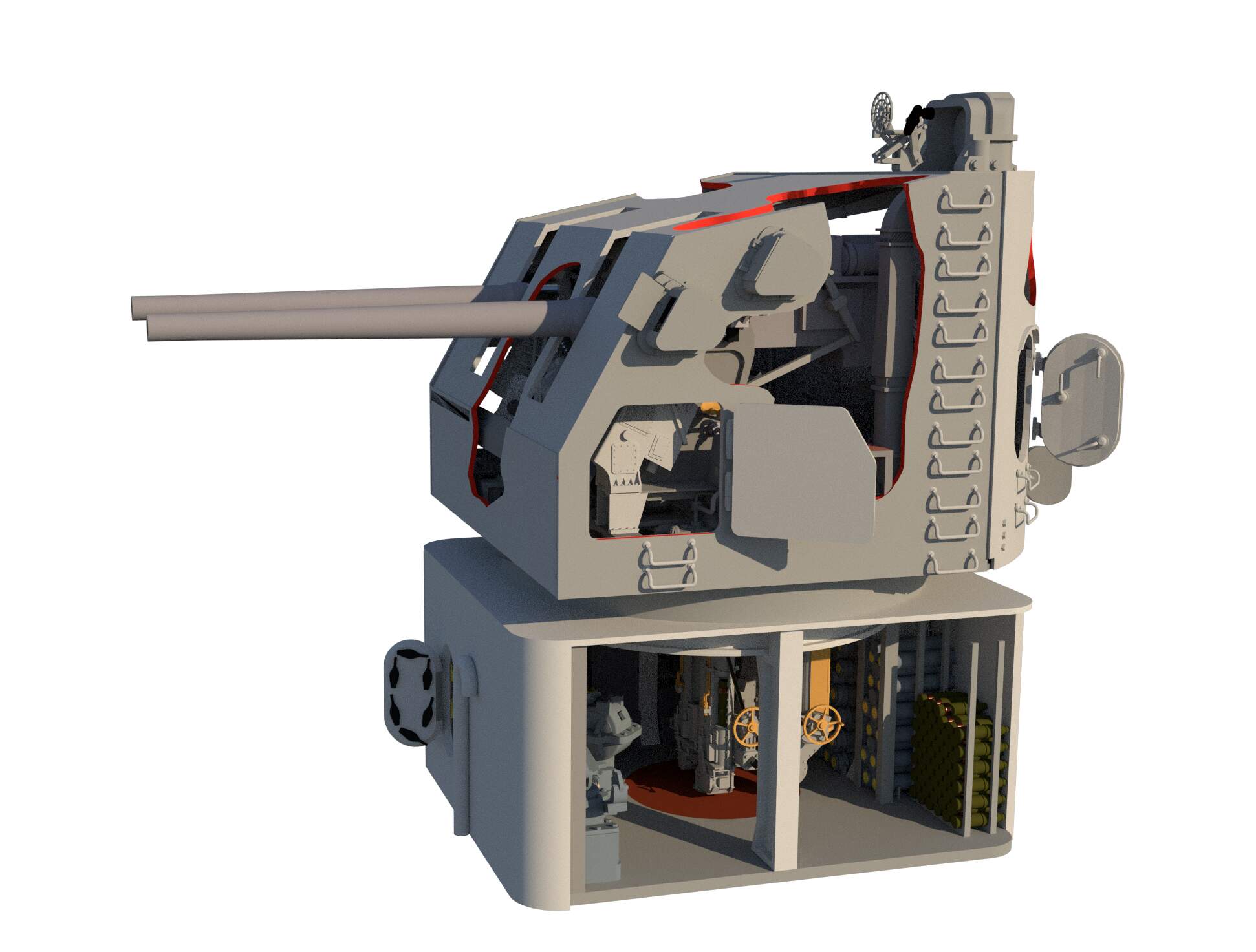
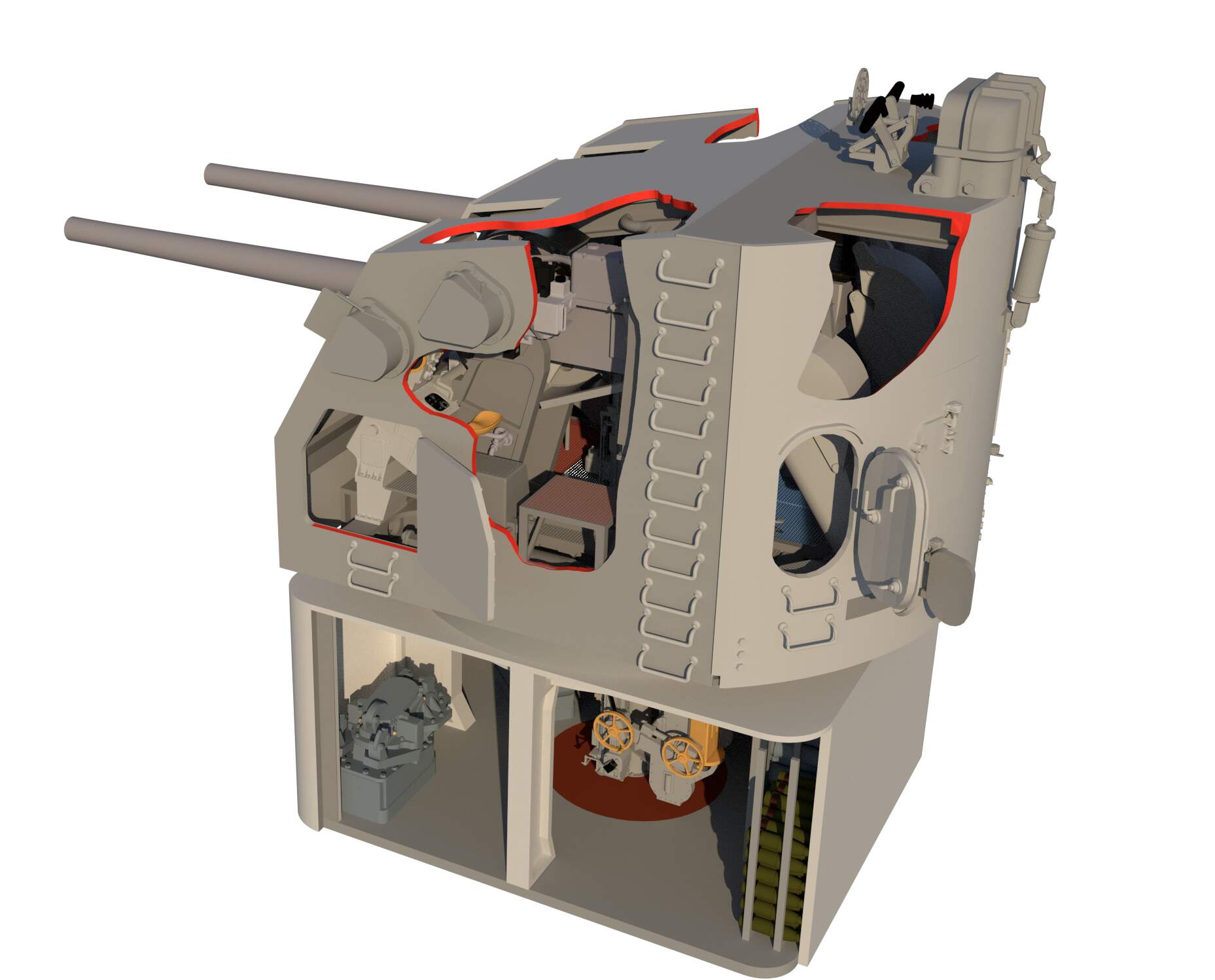
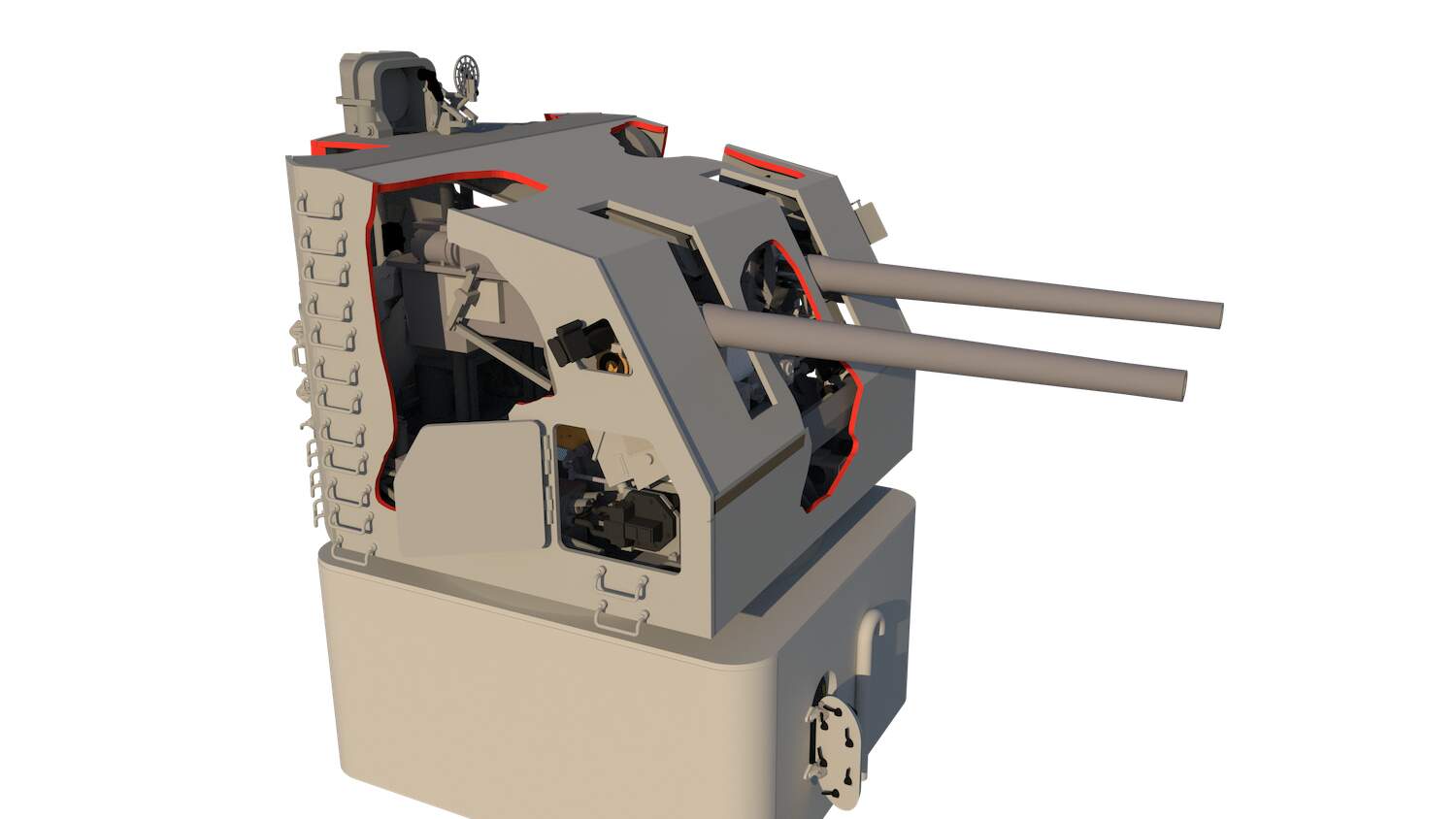
Look closely at this one and you can see the rifling in the gun barrels. The curved gun arc shiels are not in these drawings, but are on the actual model.
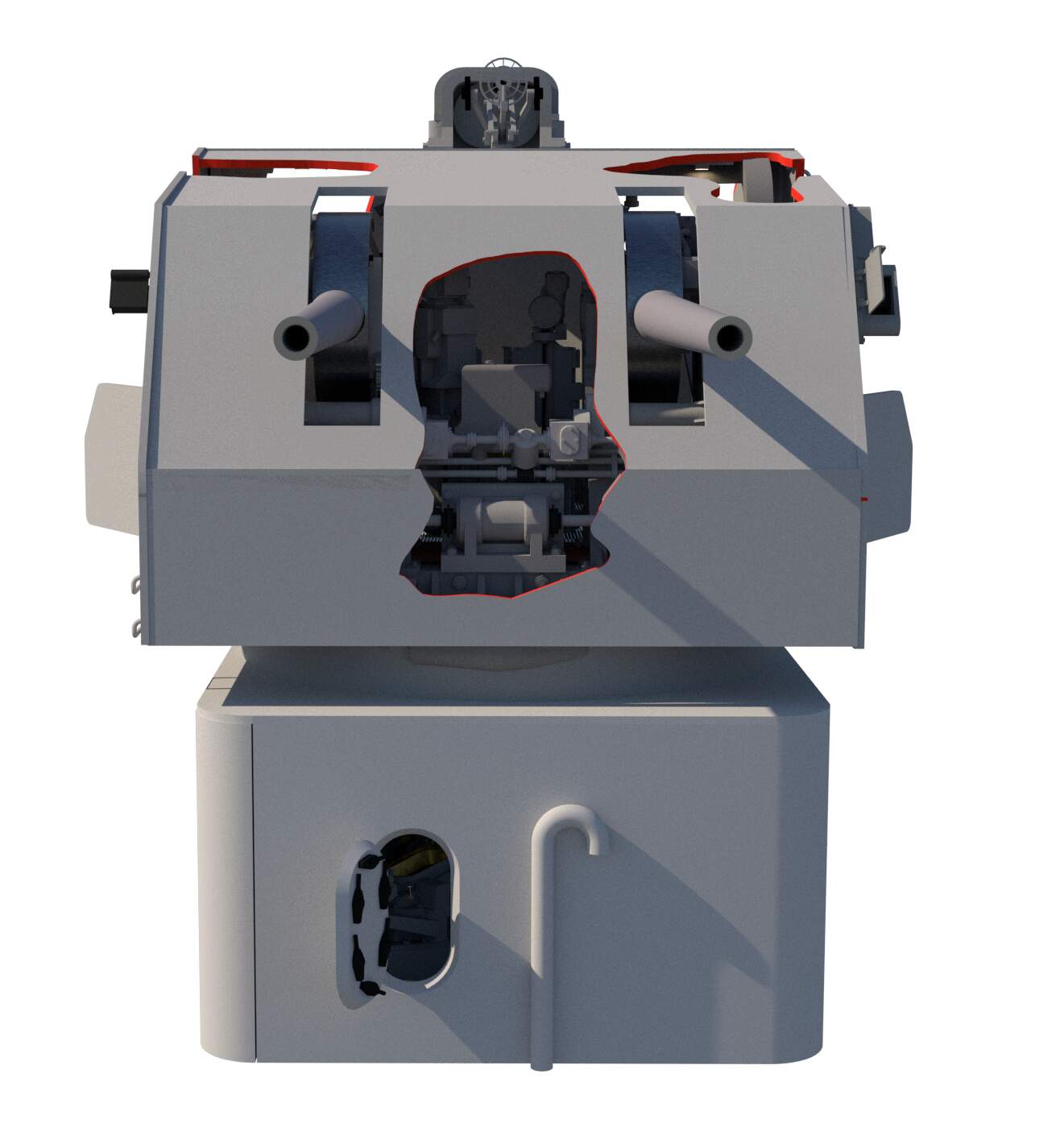
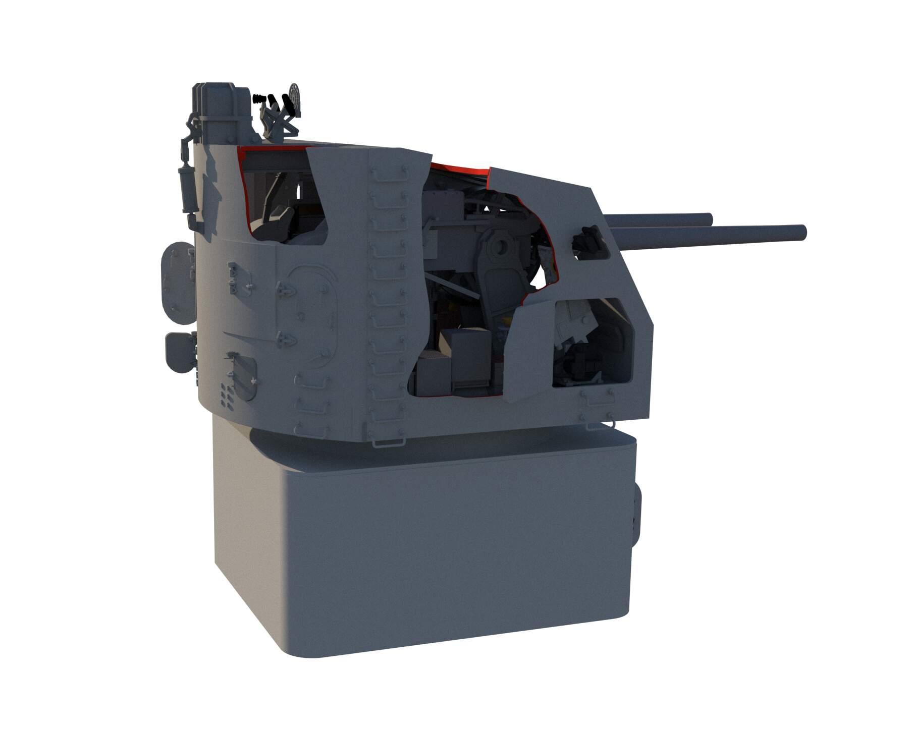
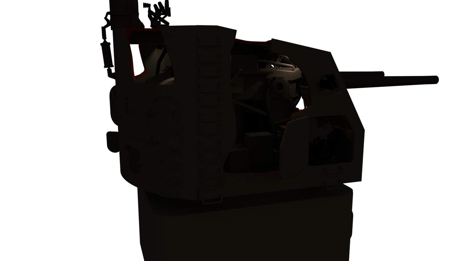
The lighting power I was using with Vray wasn’t enough. The LEDs I’m really using will be much brighter. I will be creating parterns from these drawings to accurately make the cutaways without damaging anything… or at least that’s the plan.
10 Likes
After flattening the drawing of the cutaway areas in SketchUp, I moved screen prints of the individual cut faces and imported them into CorelDraw. I then combined them in the configuration resembling a box unfolded and printed it out.
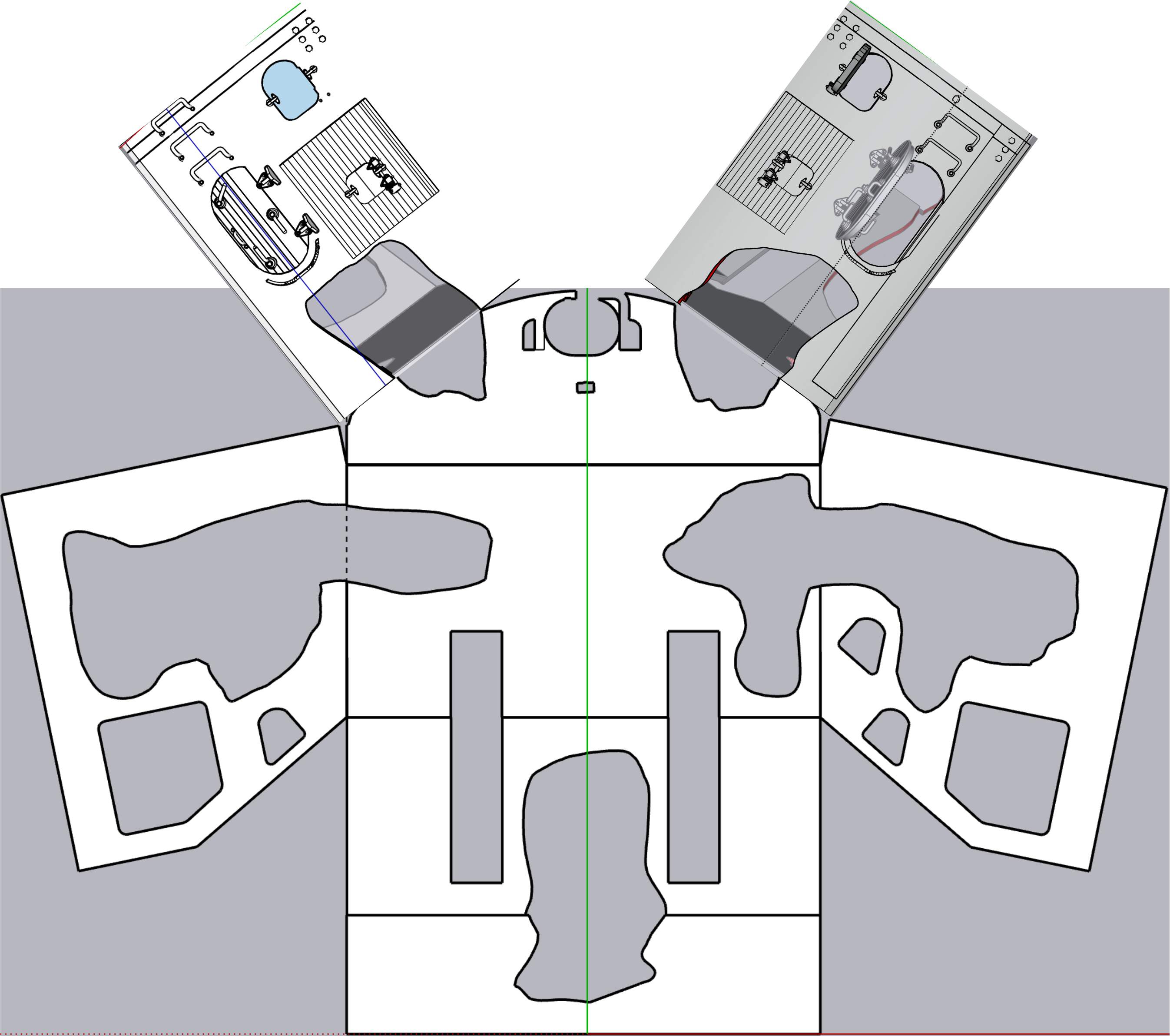
I tack glued this page to heavier stock paper abd cut the opening so I could trace the pattern onto the model.
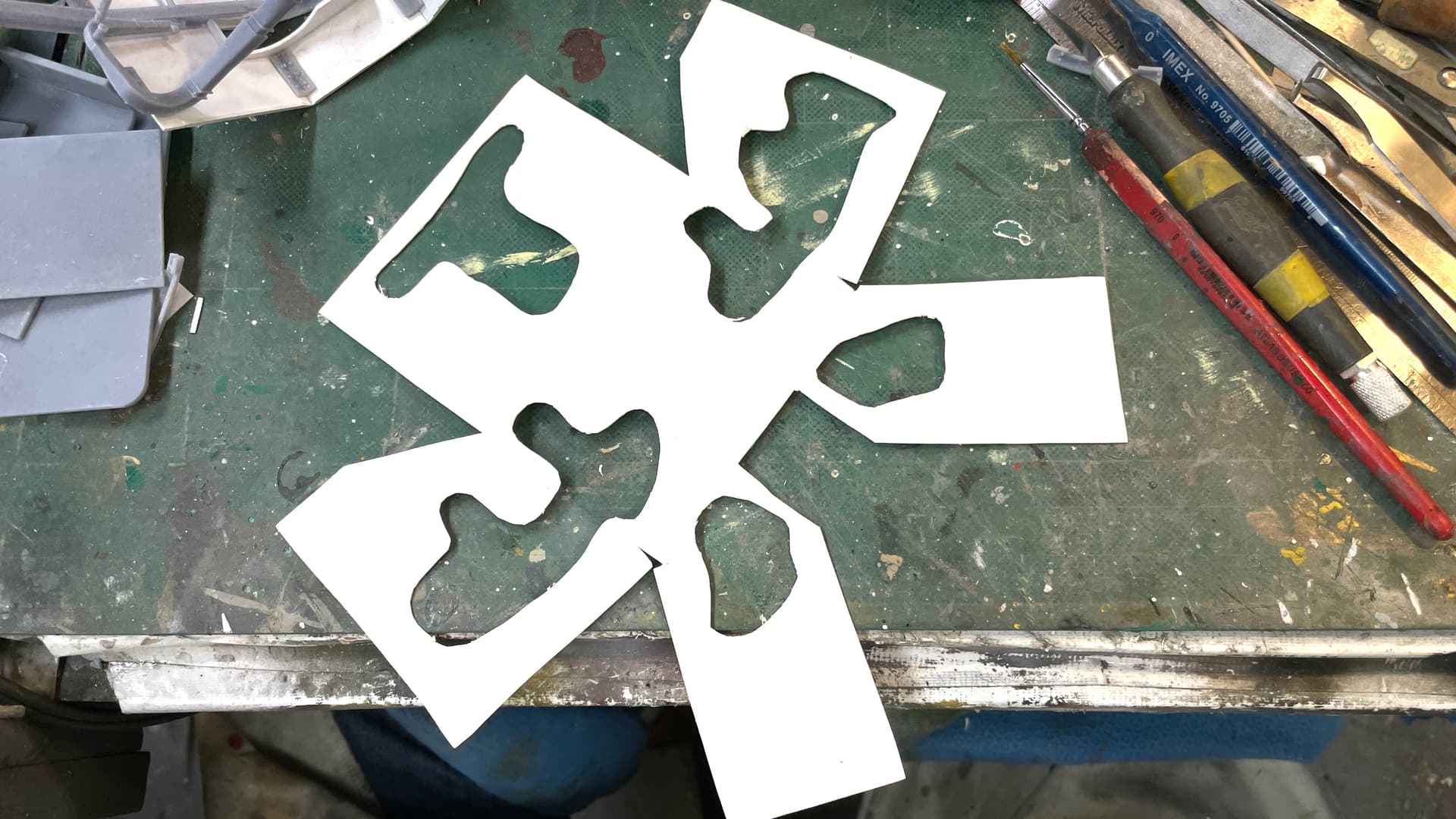
I added some pressure sensitive adhesive to the pattern to help hold it to the model for tracing, but it really didn’t do so well. I just held it in place during the trace. I had to pay attention to the lighting in the rear and be particularly careful around the ladder rungs runner up the side.
The above took place on Monday.
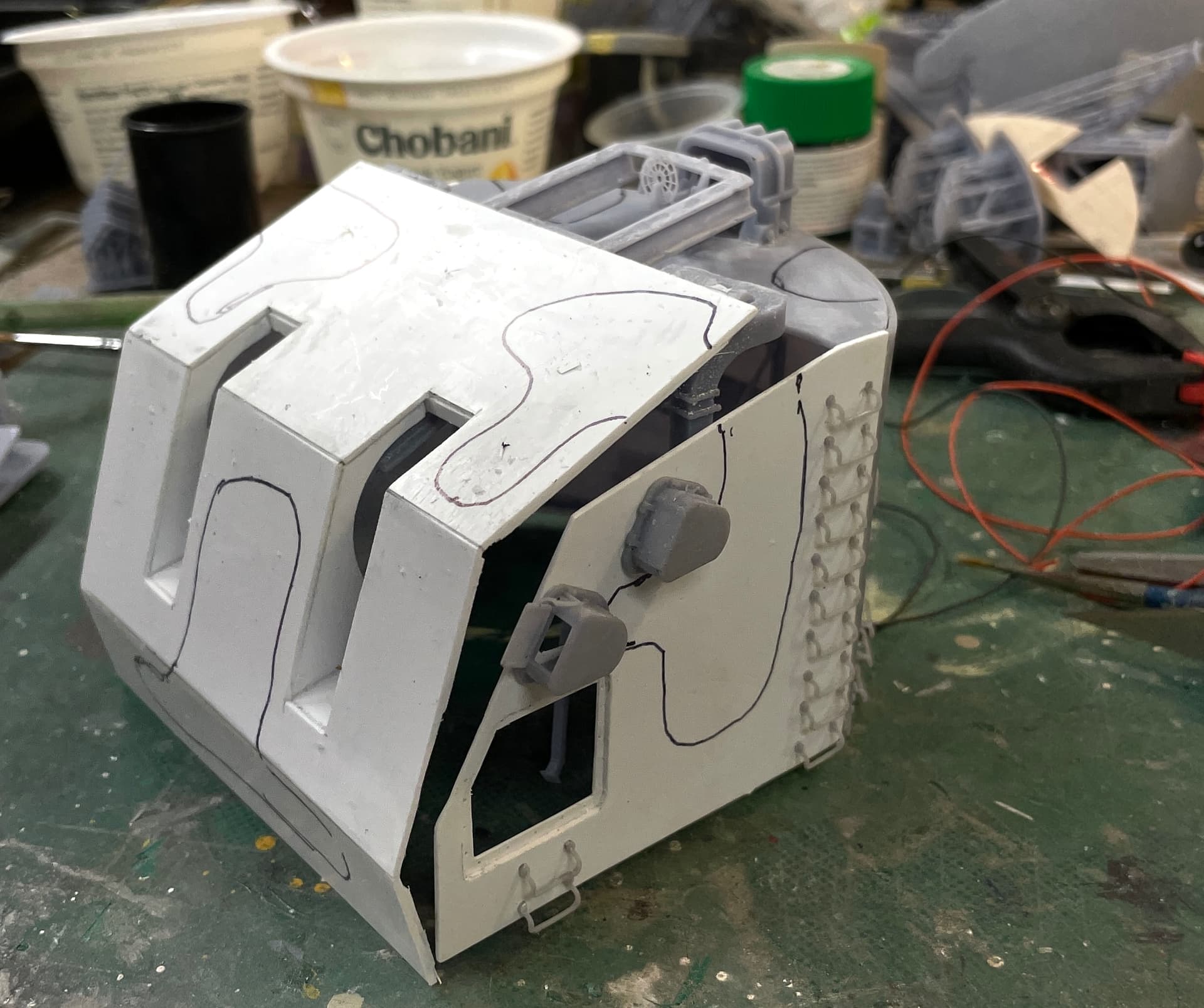
Today, I loaded a carbide router in the Dremel and went at the model. This was one of those scary kinds of modeling tasks where a false move could be a ton of rework. Since it’s a complete scratch build I do have the ability to re-create all the parts, but I don’t want to.
Before doing the cutting I mounted the rear lighting in place with the 3M Transfer Tape. Cutting went well. Actually, better than I expected.
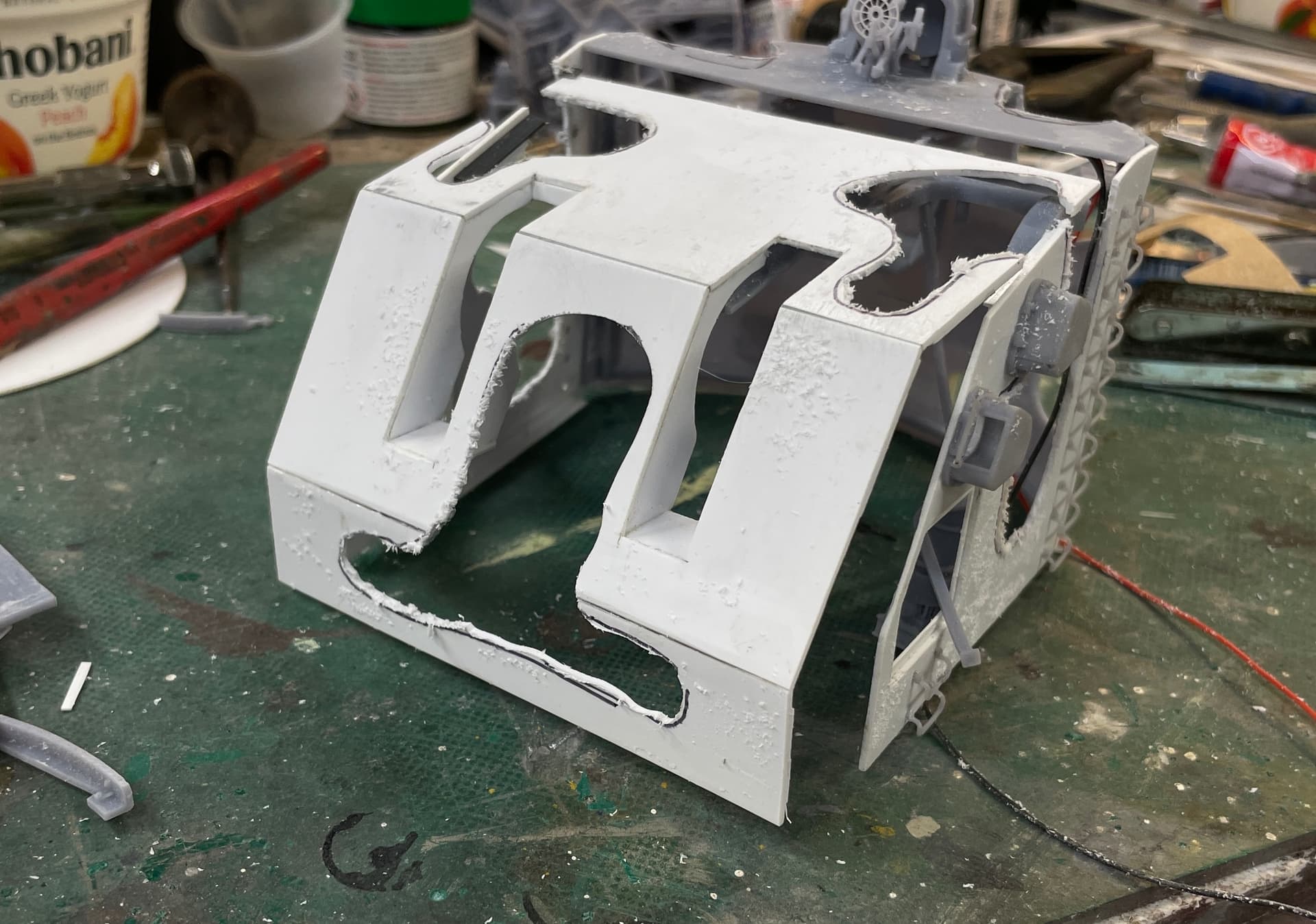
The cuts, of course, were a bit ragged. I then used the Dremel with a diamond burr to refine the contours, and finally, files, sanding sticks, and my Micro-Mark power sander to clean them up further.
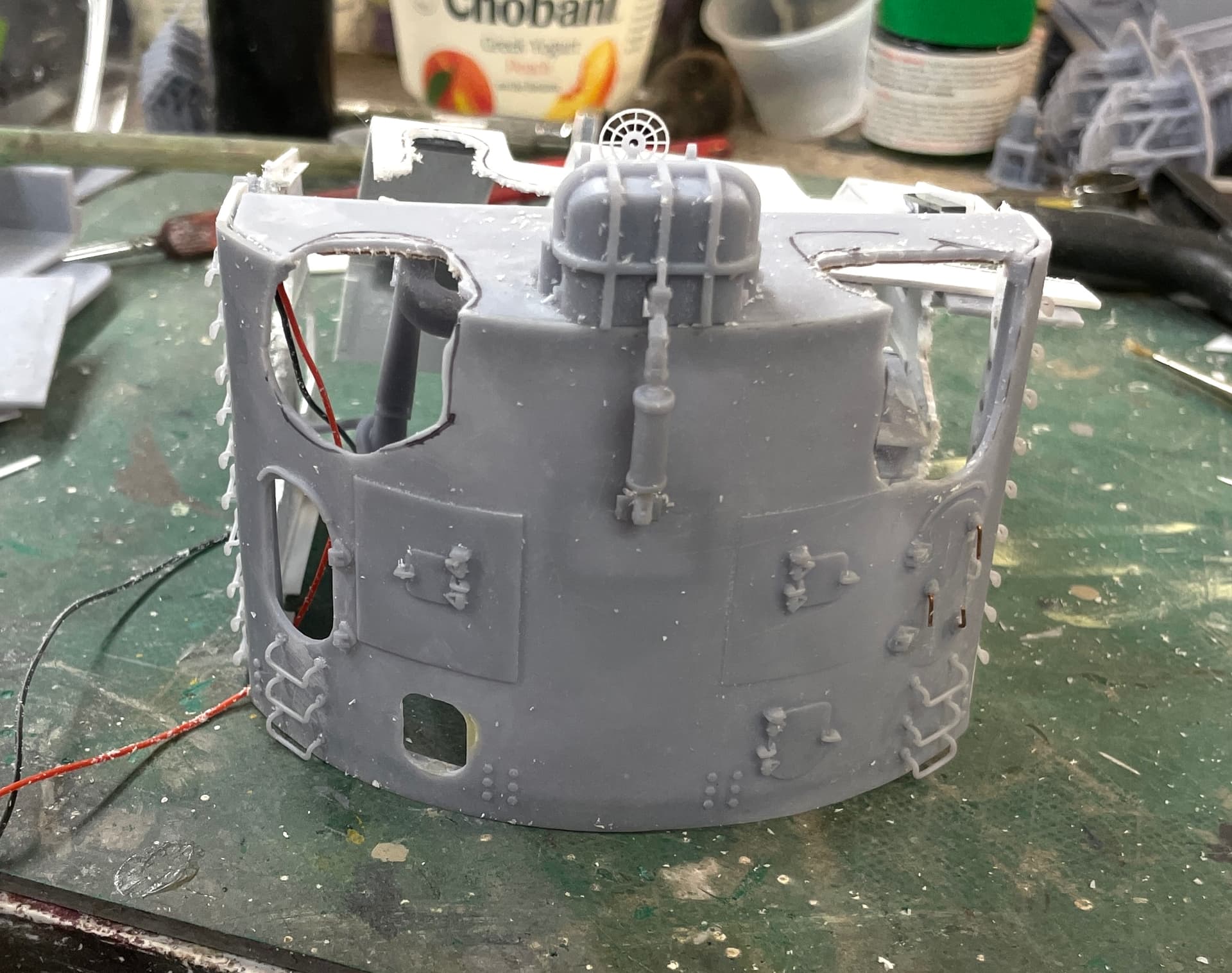
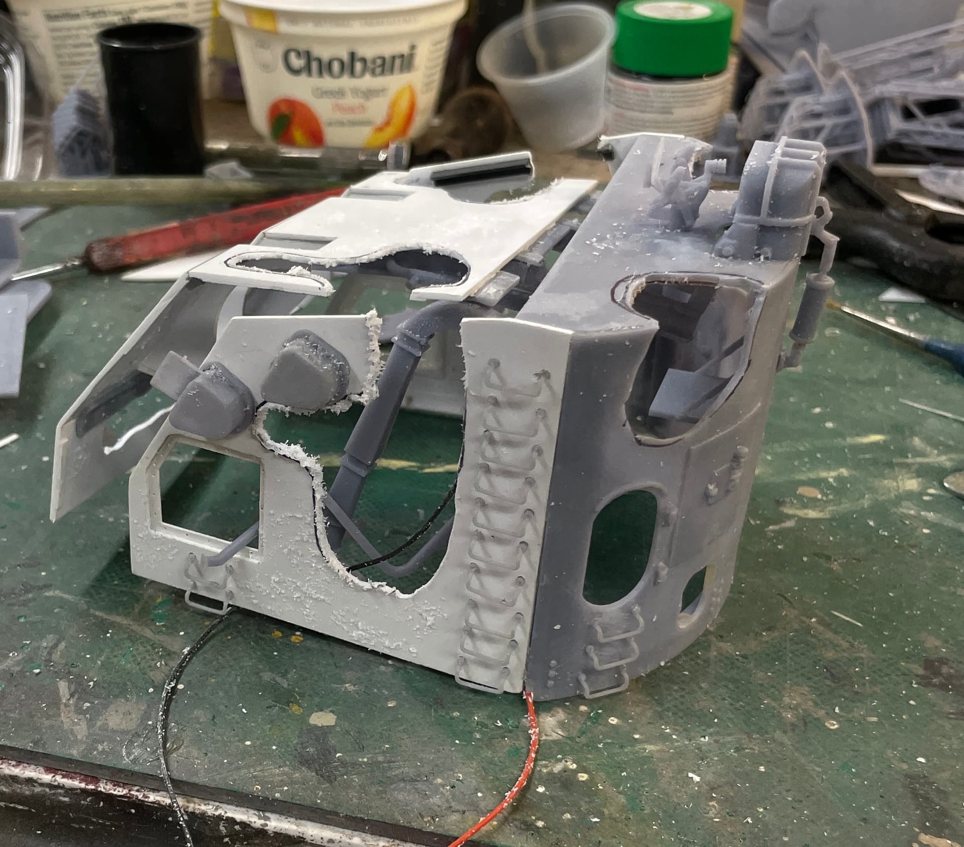
A lot of the roof is now Swiss Cheese and finding purchase for the front ceiling lights is now more of a challenge than I anticpated.
I needed to make some relief cuts on the roof beams where they cross over the rear lighting system. It’s a bit rough, but it’s the upper side and will not be visible.
I’m just about ready to prime this stuff. Today would have been a perfect day; 60 degrees, sunny and no wind, but alas, I’m not ready for that. The hobby shop has a spray booth in the back work room which I have access to. I may use that if the weather is not cooperating. Primer painting is on the critical path and I’m getting to the point where it will stop work if I don’t get it done.
You’ll notice that I whacked a couple more ladder rungs in all the rough handling during today’s session. Not to worry, I have another dozen or so printed and ready for installation. Drill out the old and install the new. Can’t do that with a kit. You break critical parts and you have to get customer service on the line to get a replacement.
10 Likes
Jeez Myles, this has been breathtaking stuff throughout but now it’s positively buttock-clenching with all that ventilating. An exceptional project.
1 Like
If all else fails… You have nailed the battle damage on the turret ![]()
![]()
Seriously, … Very nice work on the cutaways
Amazing! I can’t fathom how long it takes you to CAD those parts…
Speaking of CADing, do you have any place that you recommend to learn from? I’d like to get into it at some point, but don’t know where to start.
With SketchUp, there are a lot of free videos to get you started. I like SU since it doesn’t have a lot of parametric decisions you need to make before you make shapes. That said, you can still dial in specific measures, distances and angles at any time in the dialog box at the bottom right of the work surface. Out of the box SU is reasonably flexible. When you add the myriad of add-ons (most for free) it becomes a real power house. Like playing guitar, to get started is easy. To master it takes years. I have Meshmixer, Blender, and other packages loaded on my computer, but have used SU for so many years, changing is hard. SU is primarily architectural in nature. To do machine parts with lots of internal and external curves, Fusion 360 may be a better choice. If I was learning from scratch I might go that route. I hit shorcut keys so fast, it’s like touch typing. I don’t conciously think about it. It’s all auto-pilot. Like finding the brake pedal on the car when driving.
In a short session today I got the light installed in the front of the gun house roof. That gives three relatively bright LEDs in a small area, so I think I have enough light there.
Running out of time, I just put the GH together to see how it will fit together. I had to remove a bit of the roof girders at the rear where they impinged on the raised rib that supports the rear, semi-circular roof piece. This assembly is so critical I need to take my time. I’m going to use the Gorilla construction adhesive so I’ll have some working time to get everything in perfect alignment.
It fits together okay and will glue up as expected. I replaced the broken ladder rungs and broke two more 0.020" carbide drills in the process. These holes are getting expensive. I bought re-sharpened drills this time since they’re cheaper, but they seem to break more readily so the reduced price may not be meaningful in the long run.
And I finally decidehd how to get the gun house together. There were two problems. The sight telescopes stick out and prevent the walls from sliding down into position. And the guns! In the 1:1 world, they fully elevate the guns and drop the entire shield over top. I suspect that the telescopes aren’t even installed yet. In my case, the guns are going to be fixed at 0º elevation. Getting the gun house over the level guns would be difficult if not impossible.
Answer: Clip the telescopes at the position at the edge of the base, glue the outer portion into the blisters. You will have difficulty seeing the joint between the two parts. They’re a little long anyway and the cut can remove some of the excess length.
As for the guns, I’m going to insert them into the slides after assembly just like they do in the 1:1 world when they have to replace the barrels. Incidentally, the barrels are held with a step thread joint with a retaining bolt, so they can be removed at sea with just a half turn. I had to further reduce the slide end diameter so they will slide in easily and not cause any damage by using excessive pressure. They will be painted and may have bare metal foil on the slide area that adds some thickness.
I got a communication today from the USS New Jersey Museum that the ship will be moved to the Philadelphia Navy Yard dry dock on March 26. Bottom refurbishment will be complete some time in May. Visitors will not be allowed on board during repairs due to none of the safey systems being active. That means my deadline is now in May or later. That’s actually good. I’ve got a lot to do and rushing never works. I have other projects in the wings too, so I will be busy.
5 Likes
Back to the manger she was born in …
That’s kind of poetic isn’t it.
Last Wednesday was my wife’s 3rd of 4 chemo infusions. With the revised dosage, things are considerably better than the first session, but chemo is still awful. By attacking all cells in your body that replicate more frequently, it affects all mucous membranes, the linings of your entire alimentary canal, taste buds, lining of the mouth, and of course hair follicles. But with all that, she’s doing pretty well and the end is in sight.
My sister sent me an article in the Philadelphia Inquirer that described and entirely new vaccine approach to enable people with the BRCA 2 genetic mutation to effectively fight nascent cancer cells. BRCA mutations do not cause cancer. They eliminate one of the body’s natural defenses to kill them when they’re going rogue. This vaccine, now in human testing, injects DNA into the white cells that identify cells that are cheating by extending their telomeres at the end of the gene, thereby granting the cell immortality, when it should have died. It’s one of the cancer cells tricks to do what it does. It’s a novel approach that offers great promise.
All of this medical stuff has reduced my model building. That said, I’m still doing something.
Today, that something was to glue the gun house together, sand and then fill all of the gaps and discontinuities, secure the wiring harness, and get it ready for painting. Too bad I wasn’t further along because today was a wonderful day to paint outside… 72 degrees, sunny and fairly calm breeze. Alas, the paint will still have to wait until the GH is fully prepped.
Gluing was a delicate operation. I had to avoid clamping too hard and keep away from the ladder rungs and the gun sight on the roof. As it is I did whack a couple more rungs. No big deal. I just drill them out and replace them. I guess I should have waited until all the sanding and filling was done… 20/20 hindsight. “If my foresight was as good as my hindsight, I’d be better by a darn
sight!”
After the glue up was secure and I sanded the joints to level them, I secured the LED wiring inside. I’m running the three LEDs in series so one set of red and black leads will be tied together, It was too cramped and awkward to attempt the splice inside the gun house. Instead, I’m running all four leads out, splicing them and then running them into the upper handling room. Again, I used Bondic as liquid cable clamps.
I was then able to apply some Bondic to close any larger gaps and finish up with Tamiya Fine Putty. After curing overnight I’ll do the finish sanding, fix any broken rungs and get it primed. Don’t know what tomorrow’s weather portends yet. I’ll have to check.
I also have some bolt heads to add to the sides to line up with the framing members that lie underneath. I added these on the print, but the sides are sheet styrene. In retrospect I could have printed all of the gun house flat surfaces considering how well the upper handling room walls came out.
Speaking of the UHR, I glued three of the four walls together with thin CA and accelerator. All along I’ve been assuming that I’ll just leave off the front wall, but I rethinking that. I may want to install it and then cutaway some for viewing.
8 Likes
Today, I’m still working to get the gun house ready for paint. I did decide to build all four walls of the Upper Handling Room and then cut away viewing areas. I came to this conclusion since it makes it look more finished, and adds structural integrity.
I had to fix an addional bunch of ladder rungs. Boy! Lessons learned: put the darn rungs on at the end just before you’re going to paint. Now if only I had to make another one of these to apply this brilliance… Even with the Tenacious added into my resin mix, these fine parts are still pretty brittle.
I also added the missing bolt heads. I was able to include them in the 3D print for the rear wall, but the styrene side walls needed Tichy model bolt heads. These are styrene so they glue nicely to the styrene walls, but the only ones I had were with a screw projecting out of the nut. After the glue dried I filed/sanded them flush so they looked like my printed ones. That said, I was not particularly impressed with my precision in putting them in. I hope people don’t notice. And I broke another two 0.020" carbide drills in the process. I bought resharpend ones this time to save money. I’m not so sure it was a good decision. They’re breaking even more frequently than normal.
As I noted above, I assembled all four wallls of the UHR. I had to wet sand the top edge to make sure they were all flush. I have a piece of 400 grit wet and dry paper glued to my Rock of Ages granite surface plate that I use when I want a surface really flat. I drew the cutaway profile with a Sharpie and cut it out with the Dremel and carbide router. I final sanded it with the same Dremel with a sanding drum. Sanding cured resin is nice, unlike styrene with melts almost immediately. It’s a thermoset plastic and does not melt with heat applied.
I also noted on the upper frame piece where the UHR lighting is going since that is up next.
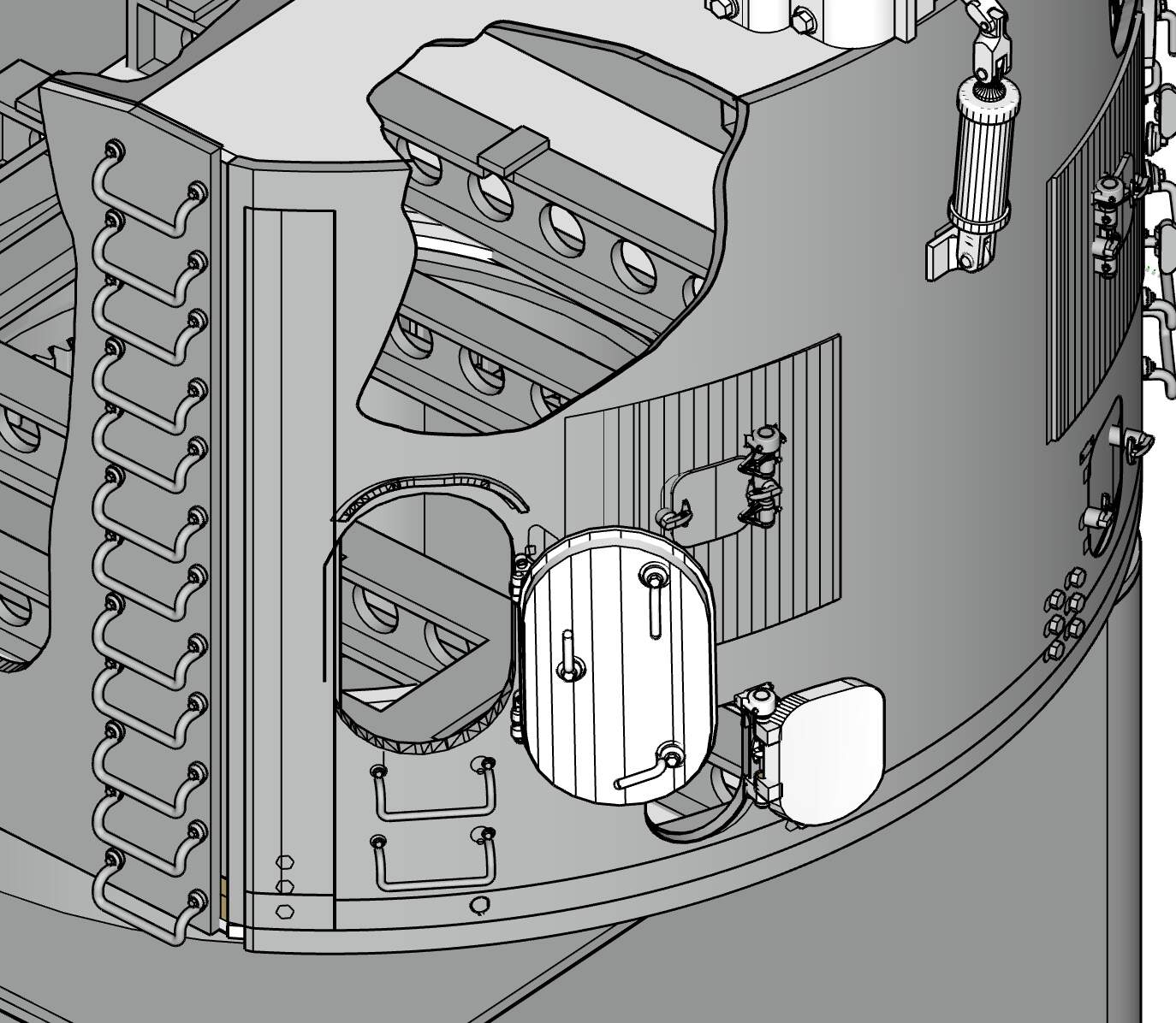
I’ve put a request into Ryan to take some pictures of the communications and controls that flank the gun captain’s position at gun house rear. That detail is the last thing needed to be drawn and printed for the upper works. I’m still wrestling with the below decks stuff.
6 Likes
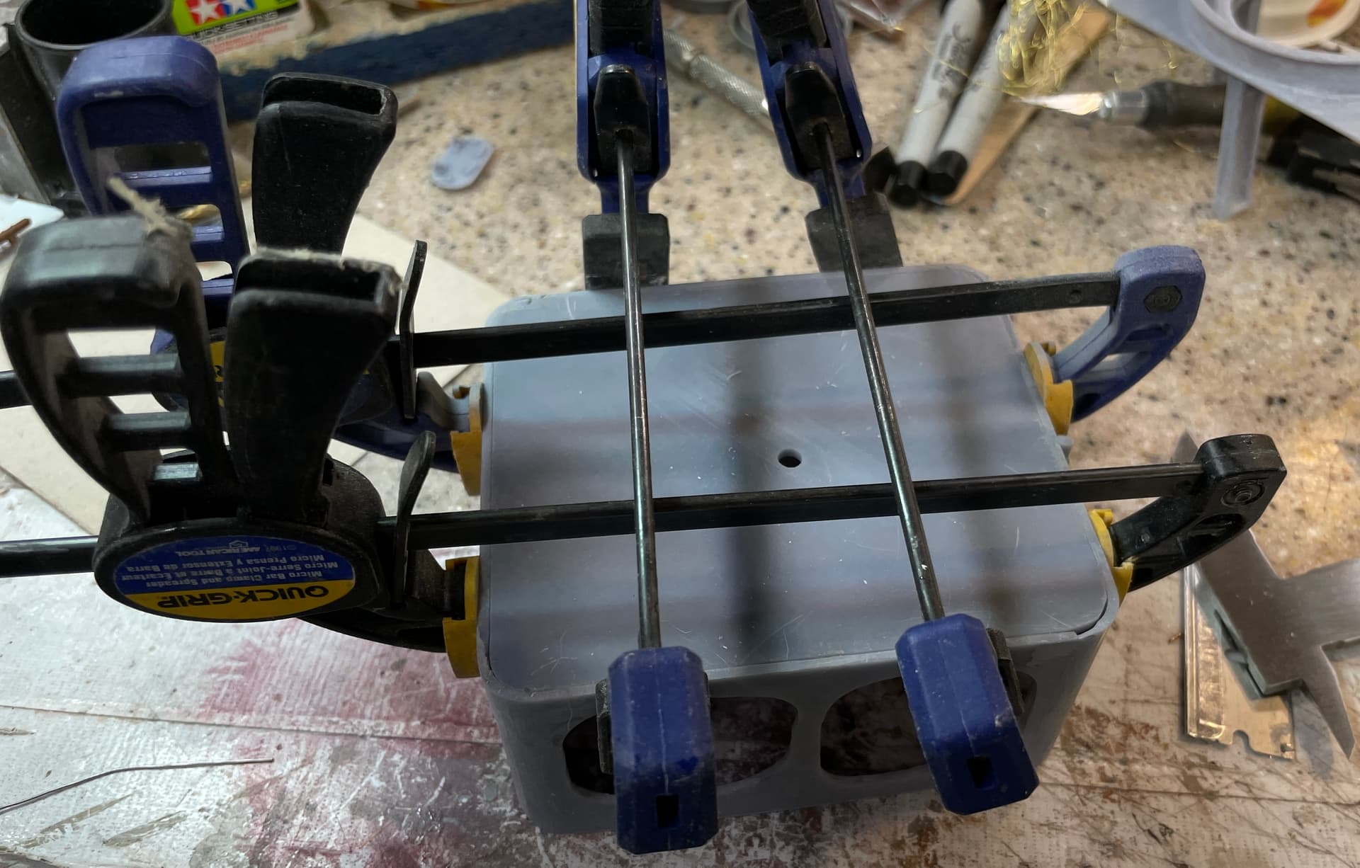
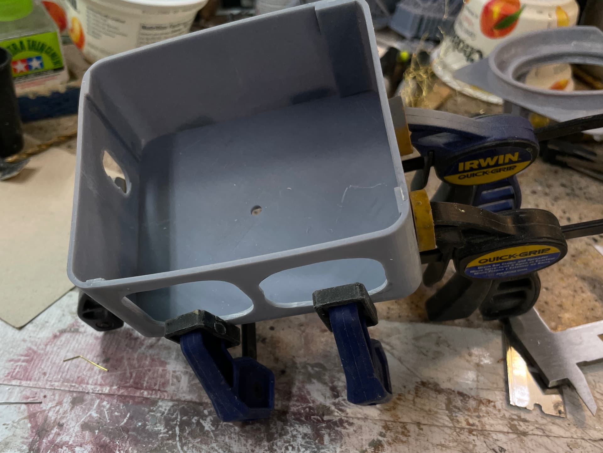
I filled and sanded the UHR walls. I then clamped the floor in place and glued it with thin CA, run as a bead on the inside on a surface pre-treated with accelerator. My work table is a piece that I bought from IKEA in Venlo, the Netherlands, when we lived in Düsseldorf, Germany in 1999 to 2002. I put on a cork tile surface. On top of that is a piece of Corian that is the sink space slug removed from the counter top in our current home. Corian is a great work surface. It’s dead flat, smooth, and impervious to every solvent we use. I normally then cover it with a cutting matt, but when I want to align something for gluing I work directly on the Corian… like I did today when I wanted the bottom to be fully flush with all four sides before gluing.
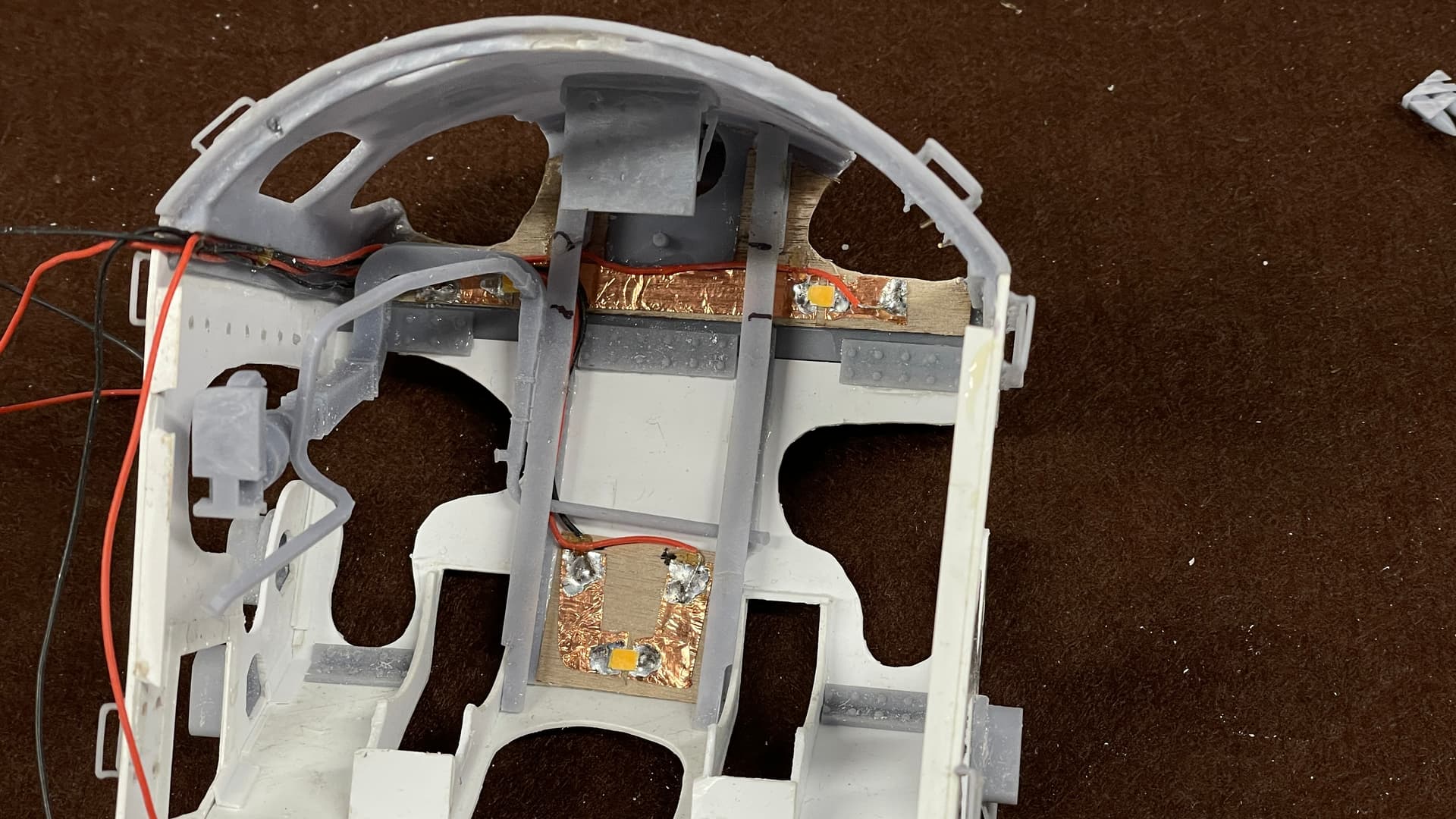
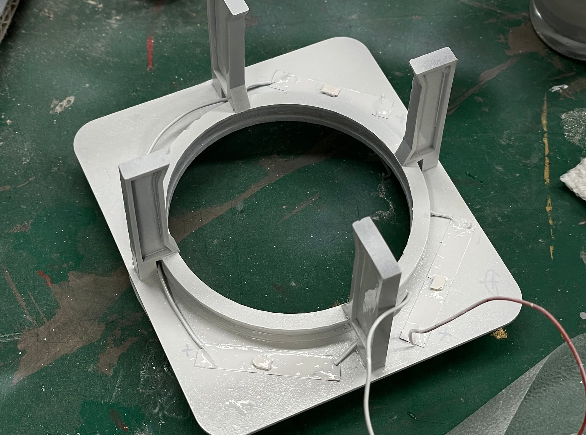
I also final fit the roof and ring support. It needed some triming for clearance of one of the legs so it would center properly. I marked the position for the lighting and installed them via the copper tape method. One girder was a little long and needed some light sanding.
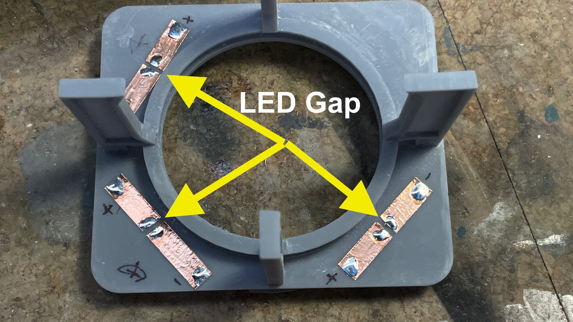
Lighting Install:
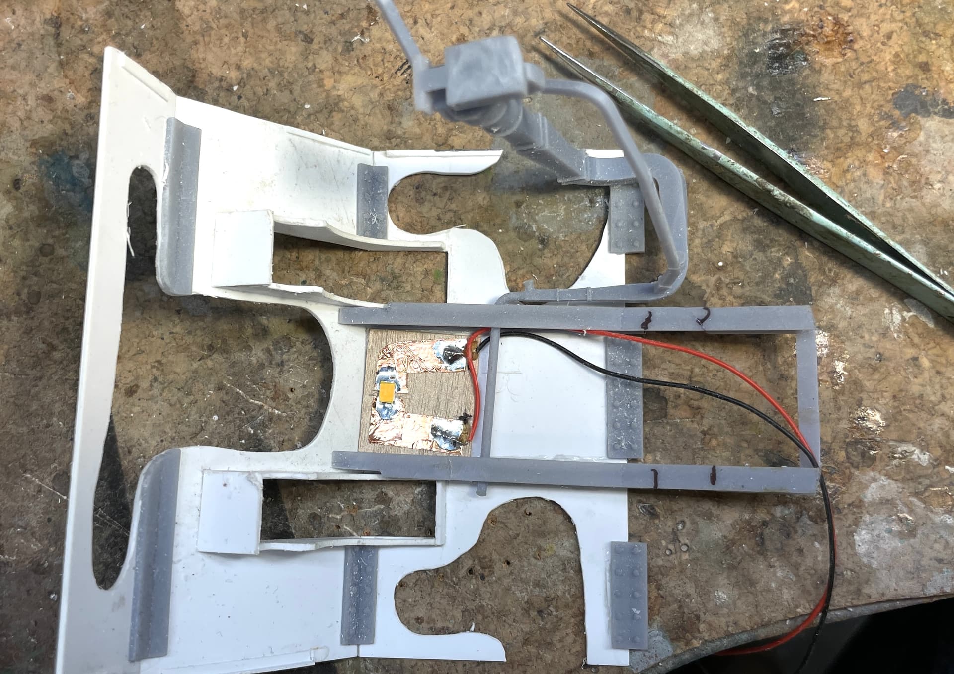
This image shows the tape arrangement with the gaps cut for the SMLEDs. The distance from the anode and cathode terminals is just about a millimeter so you can have to very precise in setting the LED in place for soldering.
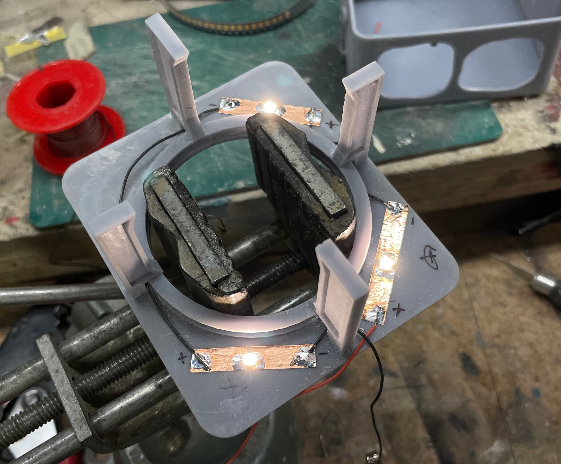
I test the LEDs before soldering, after soldering each LED and then ther entire circuit. This was the circuit test. After the test I put some Tamiya masking tape tabs on each in prep for paint.
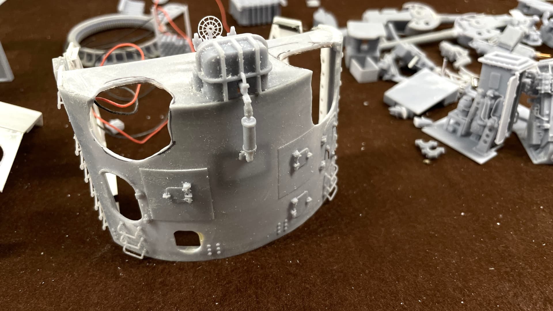
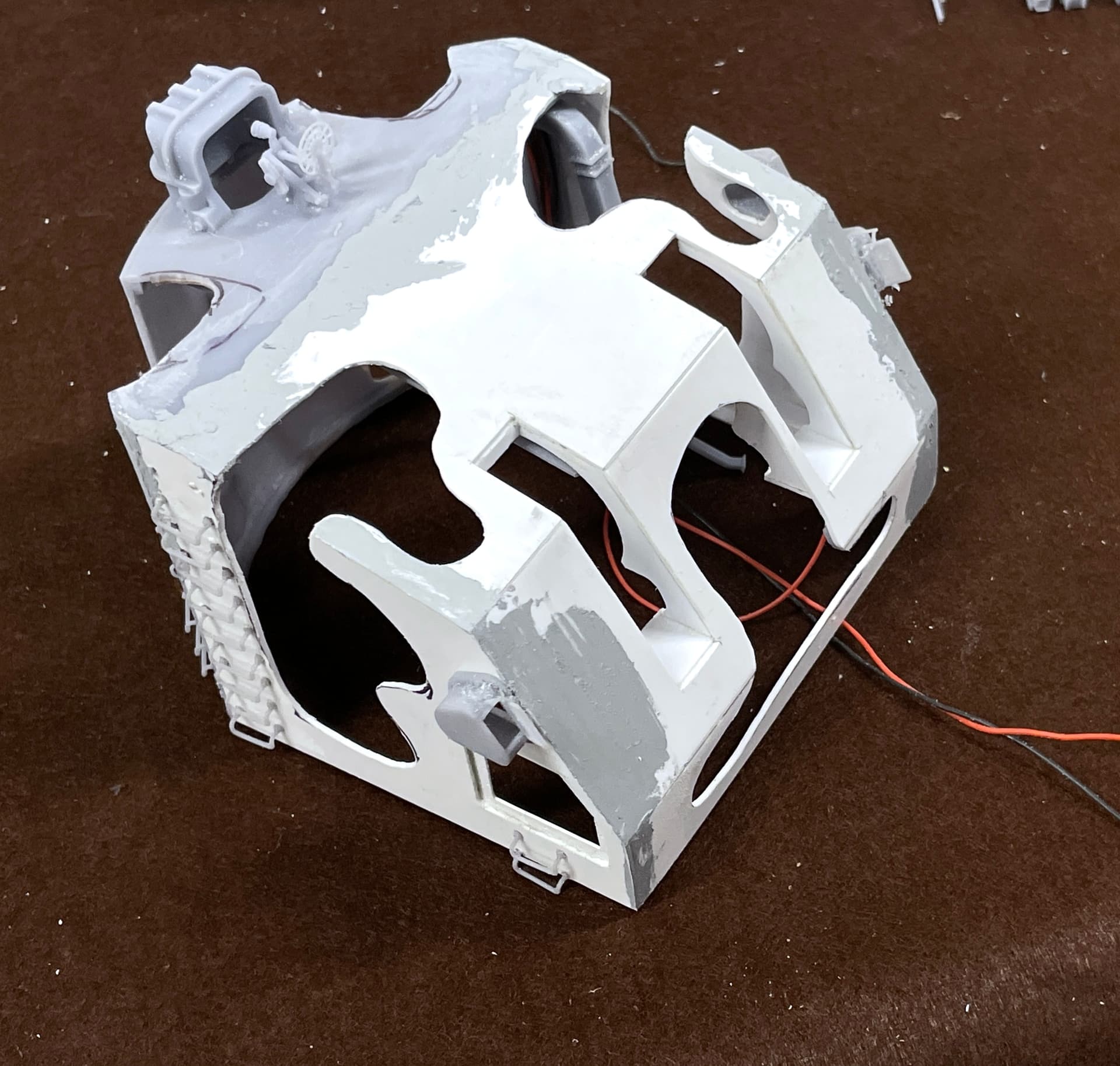
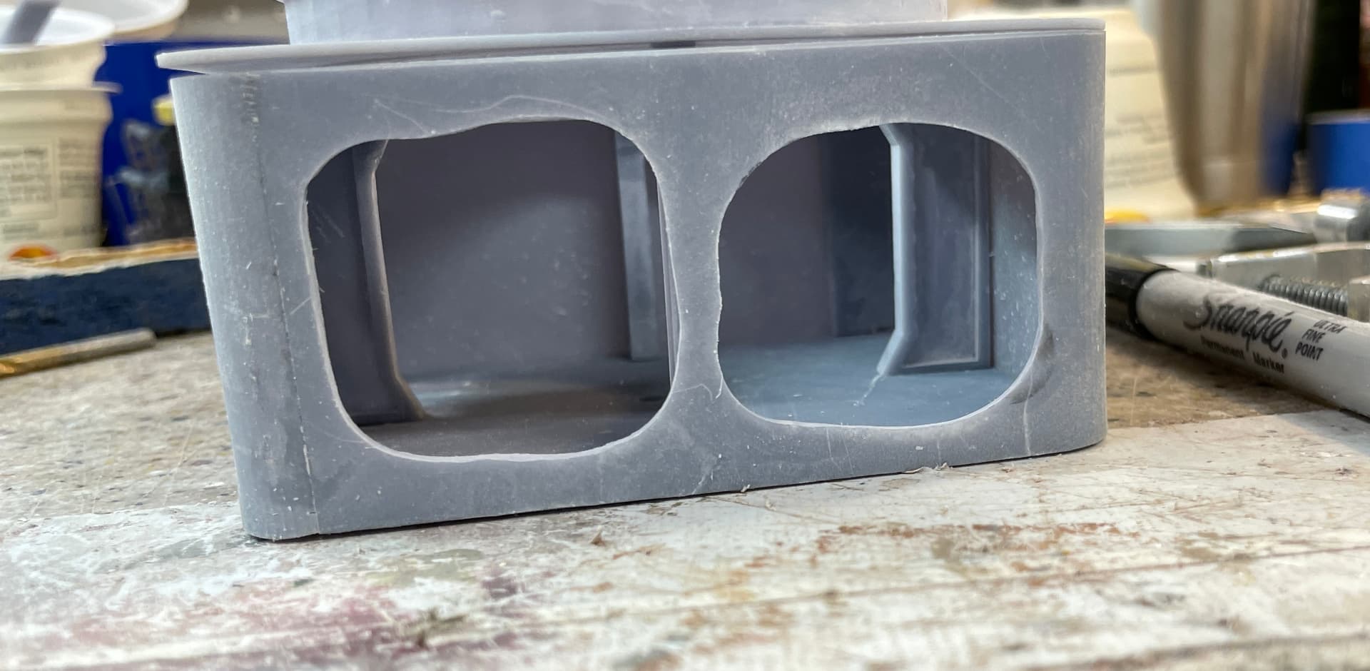
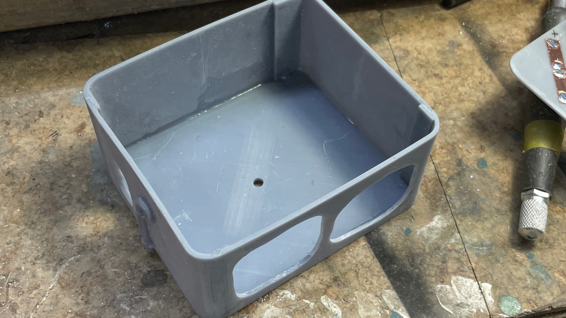
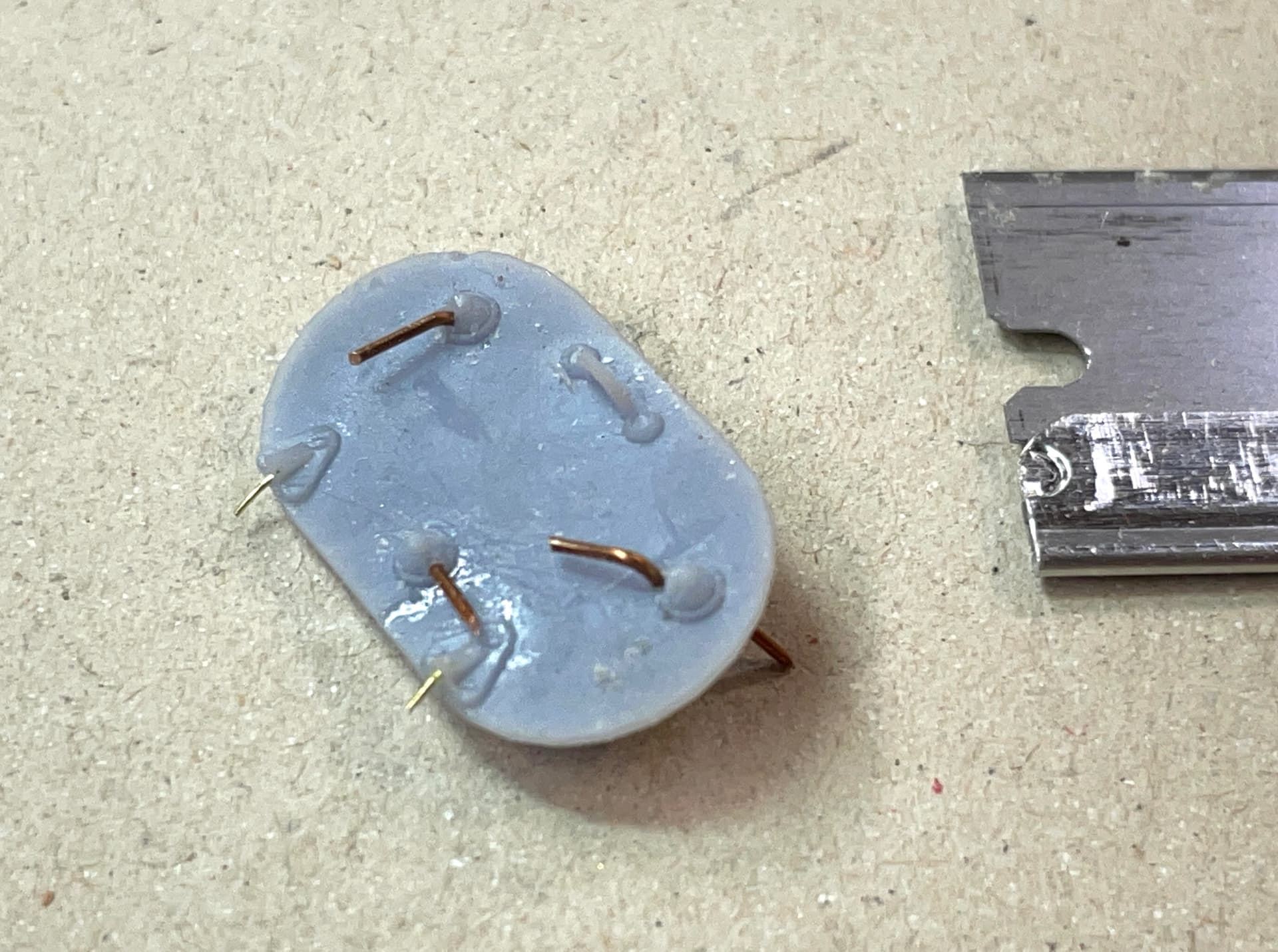
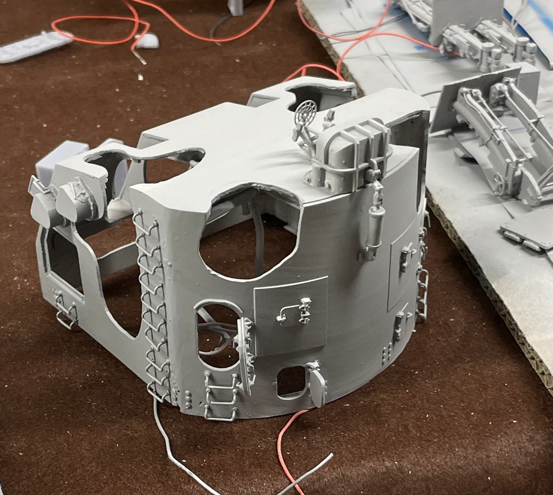
I put the lid on the box and looked at the light produced. Un-painted, the light leaks through the semi-translucent resin walls. There will be two coats of paint on inside and outside: white primer and gloss white inside and gray primer and haze gray on the outside. I don’t think the light will leak then.
This is another series circuit with three LEDs so the +/- string daisy chains to the starting point. I will combine all the black leads back to the circuit board, and all the red leads will have their own CL2N3 on the board to drive them. That cuts down the absolute number of leads that has to go below. The entire circuit is operating at 20 milliamps so current loading is not a problem. I could have run the entire circut with copper tape, but the opennings through each girder would meant the tape be folded to get through and I wasn’t going to attempt that.
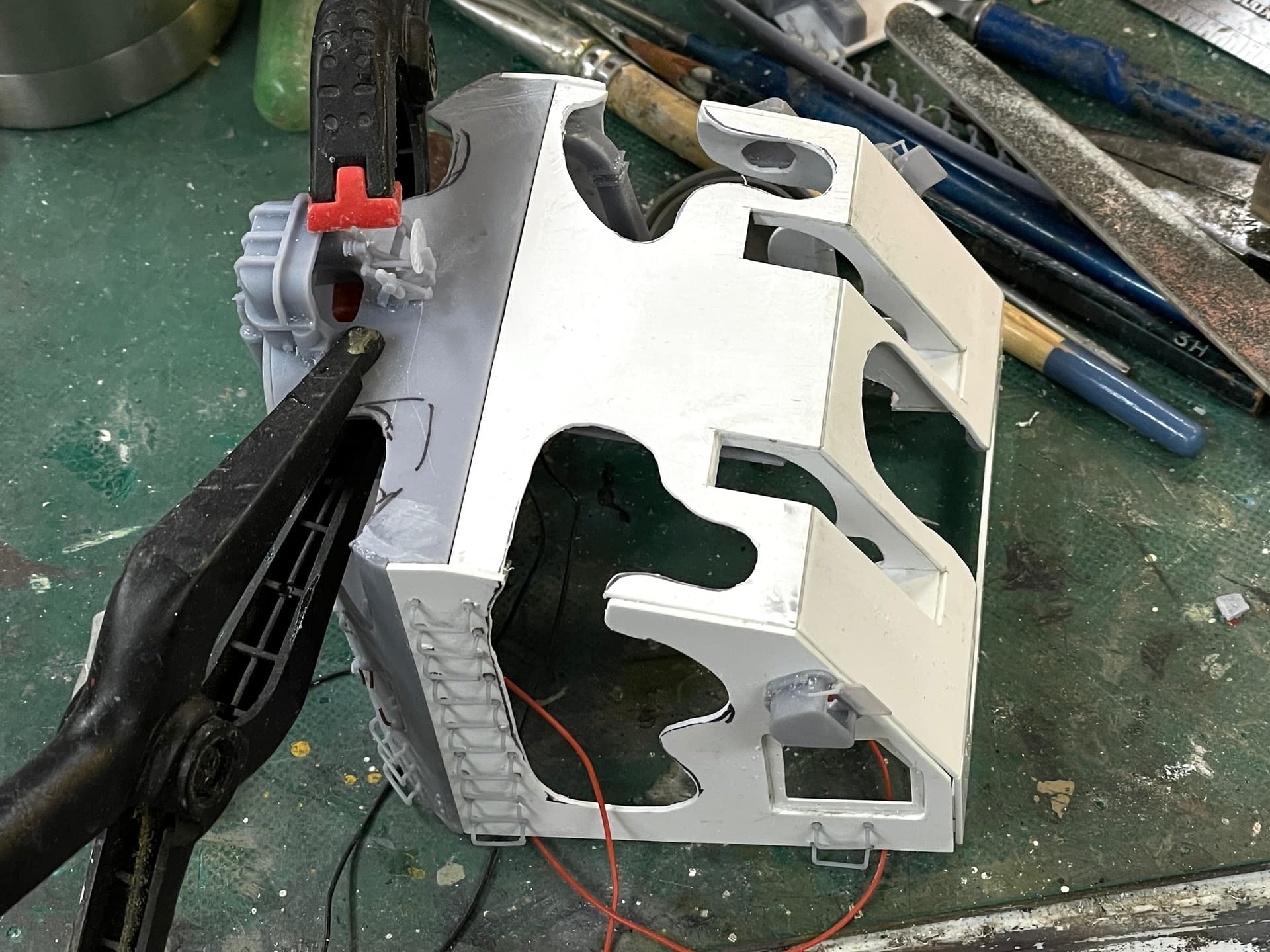
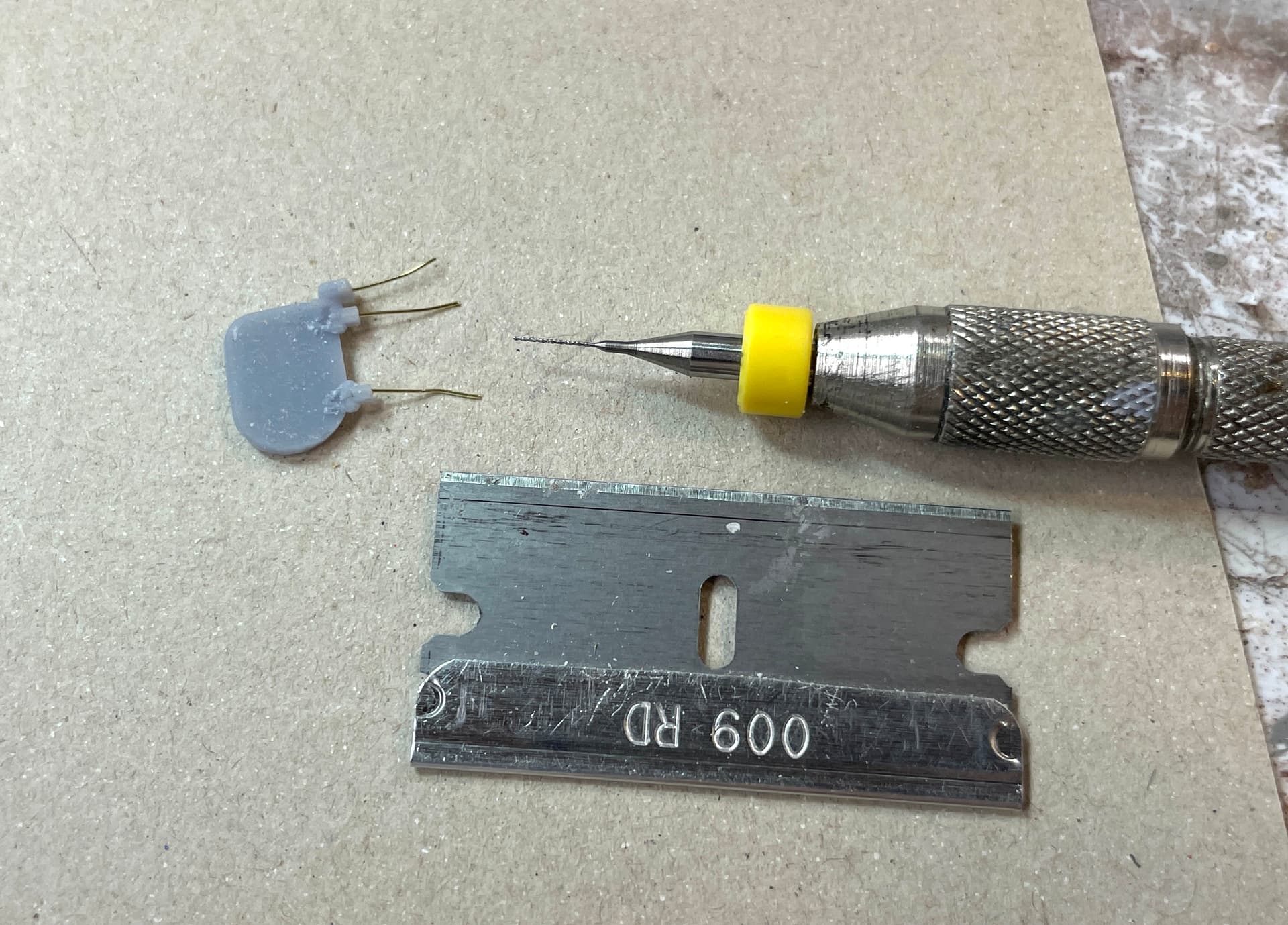
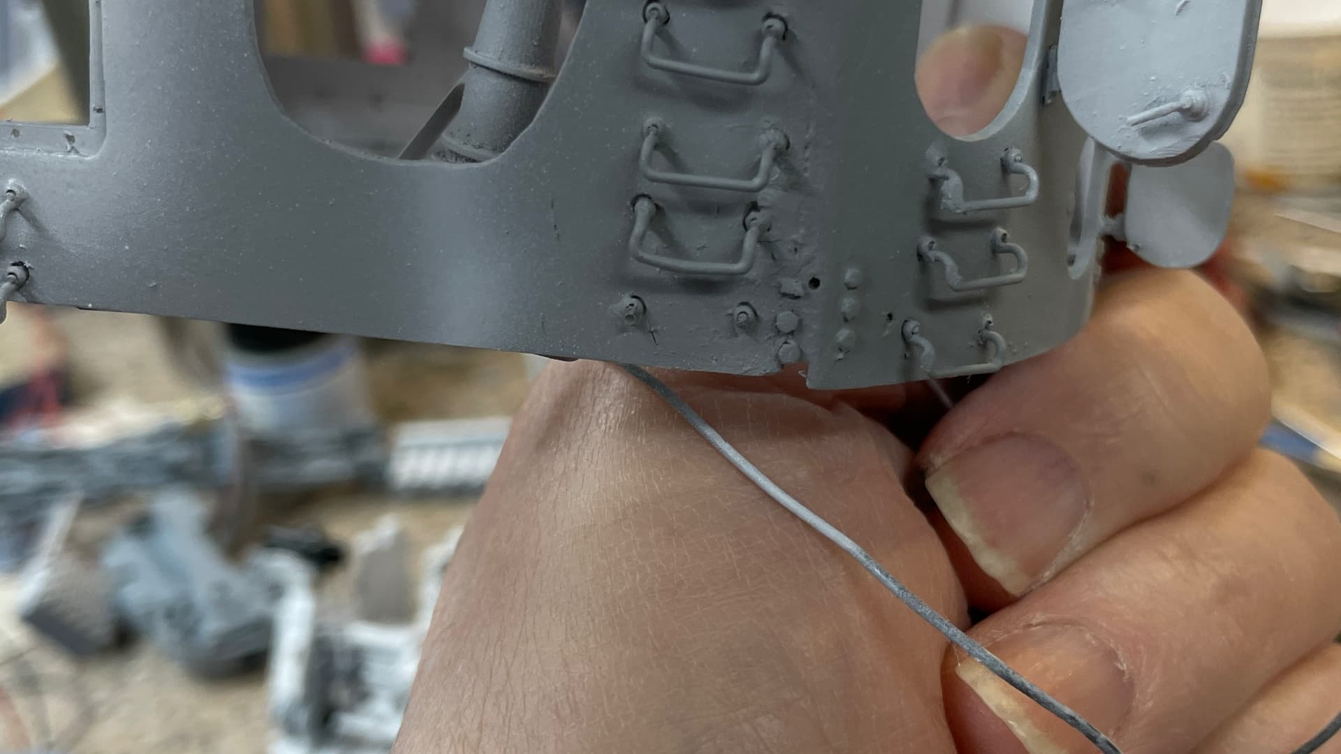
To comlete the gun house for paint I decided to put the open doors back on. This time with wire reinforcement. I used a very fine, 0.012" carbide. Believe it or not, I didn’t break this one at all. I used 0.012 brass wire for the small cartridge discharge door, but it was too flexible. I changed to guitar string of the same gauge for the big door. I used Xuron hard wire cutters for the music wire. I have a 40 year old pair of Channellock long nose pliers with a wire cutter in the handle end to cut hardened wire and it doesn’t do anything to them. When I use other cutters like Xuron regular cutters or any Chinese cutters, they get a semi-circular divots in the cutting edges and it ruins them.
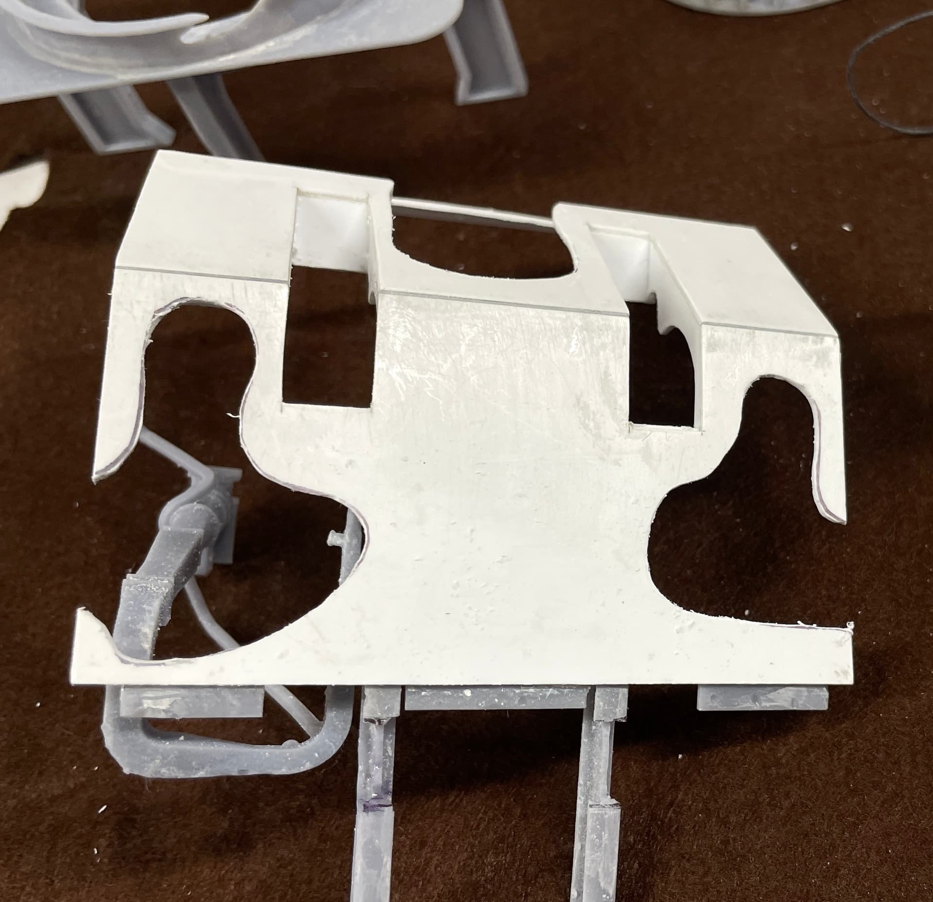
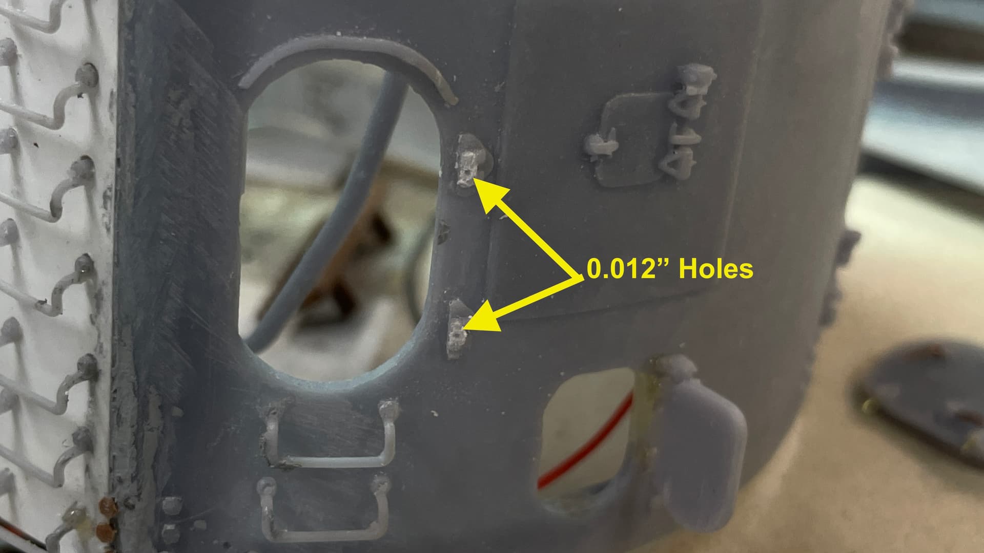
This images shows the holes in the wall side. The holes are so small that I can’t really see them without the Opti-visor.
The wired doors are much stronger. I also broke and fixed at least three ladder rungs and there’s still a few more to do. The problem is every time I grab it or put it down on the bench, I’m hitting them. I may reprint more and not post-harden them quite so much so they aren’t quite so britte.
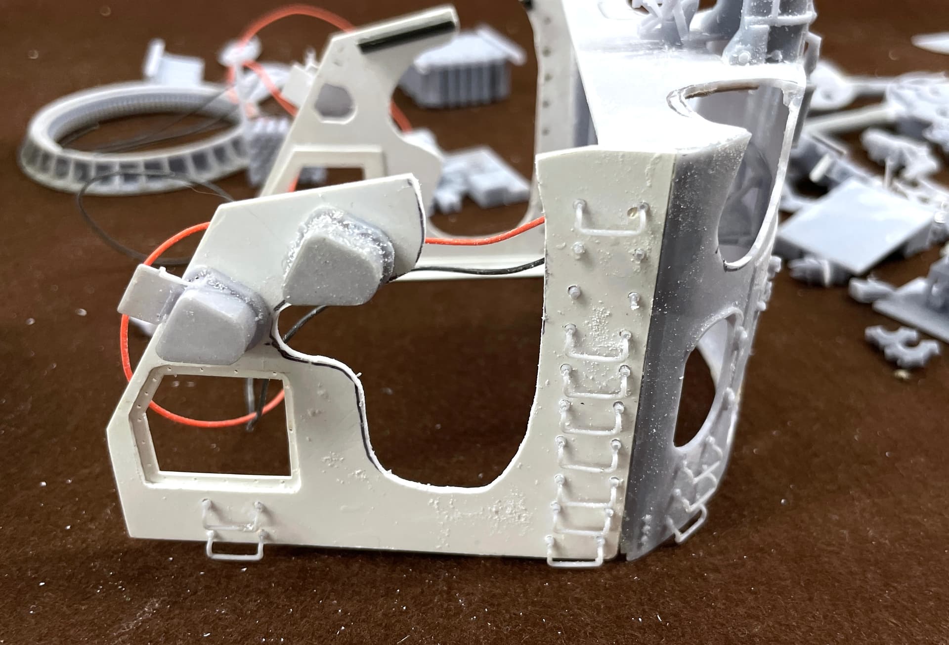
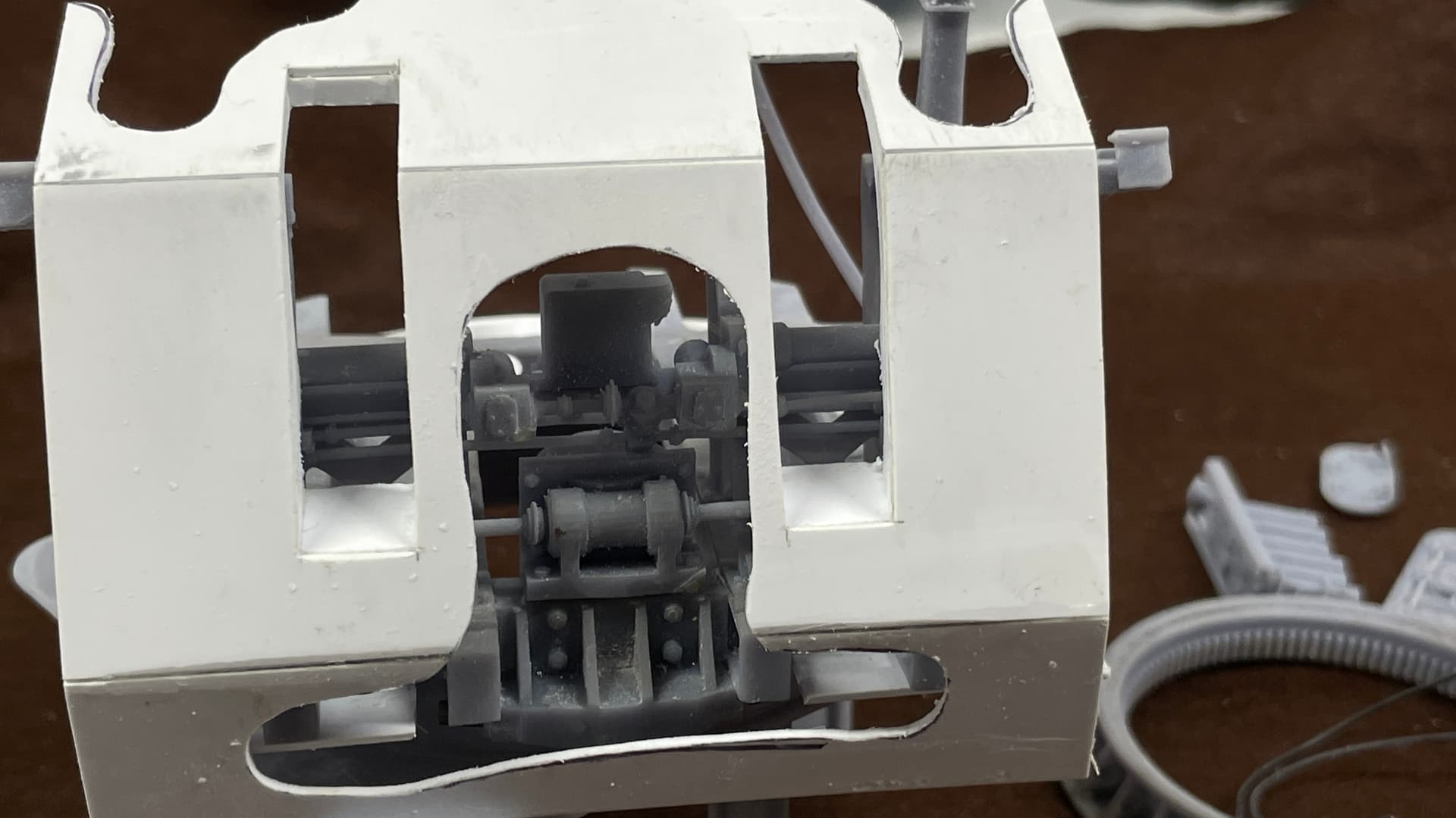
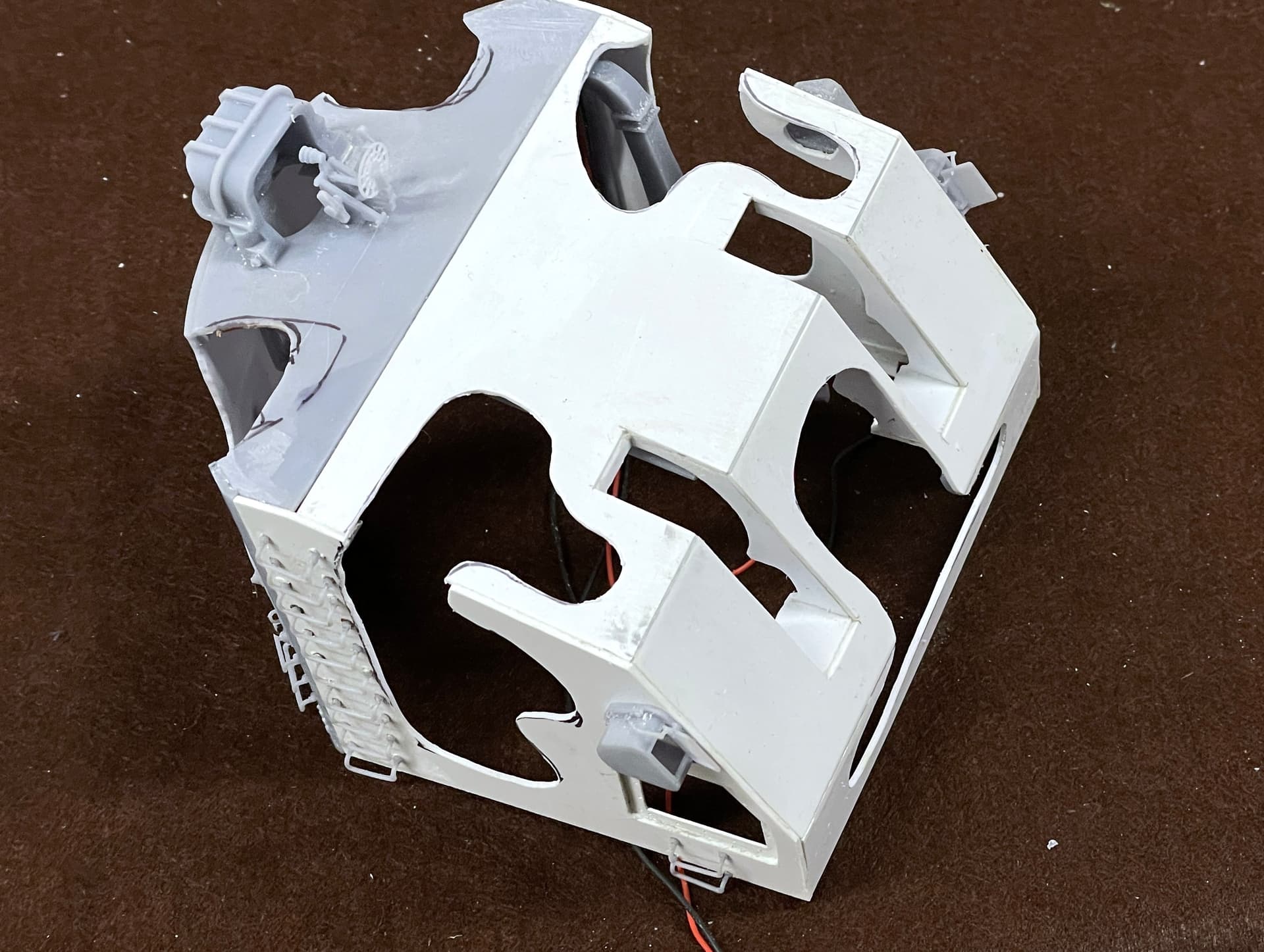
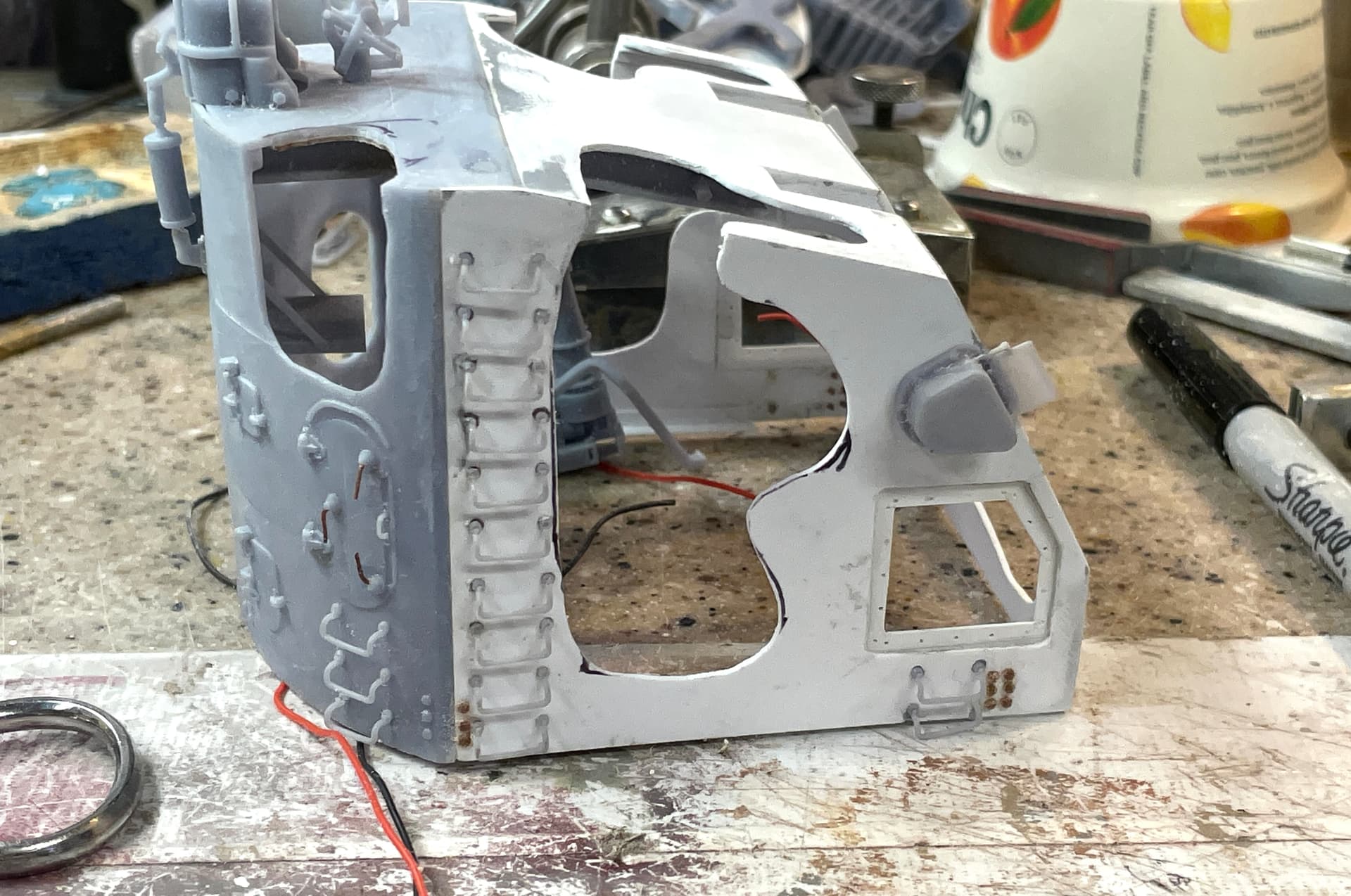
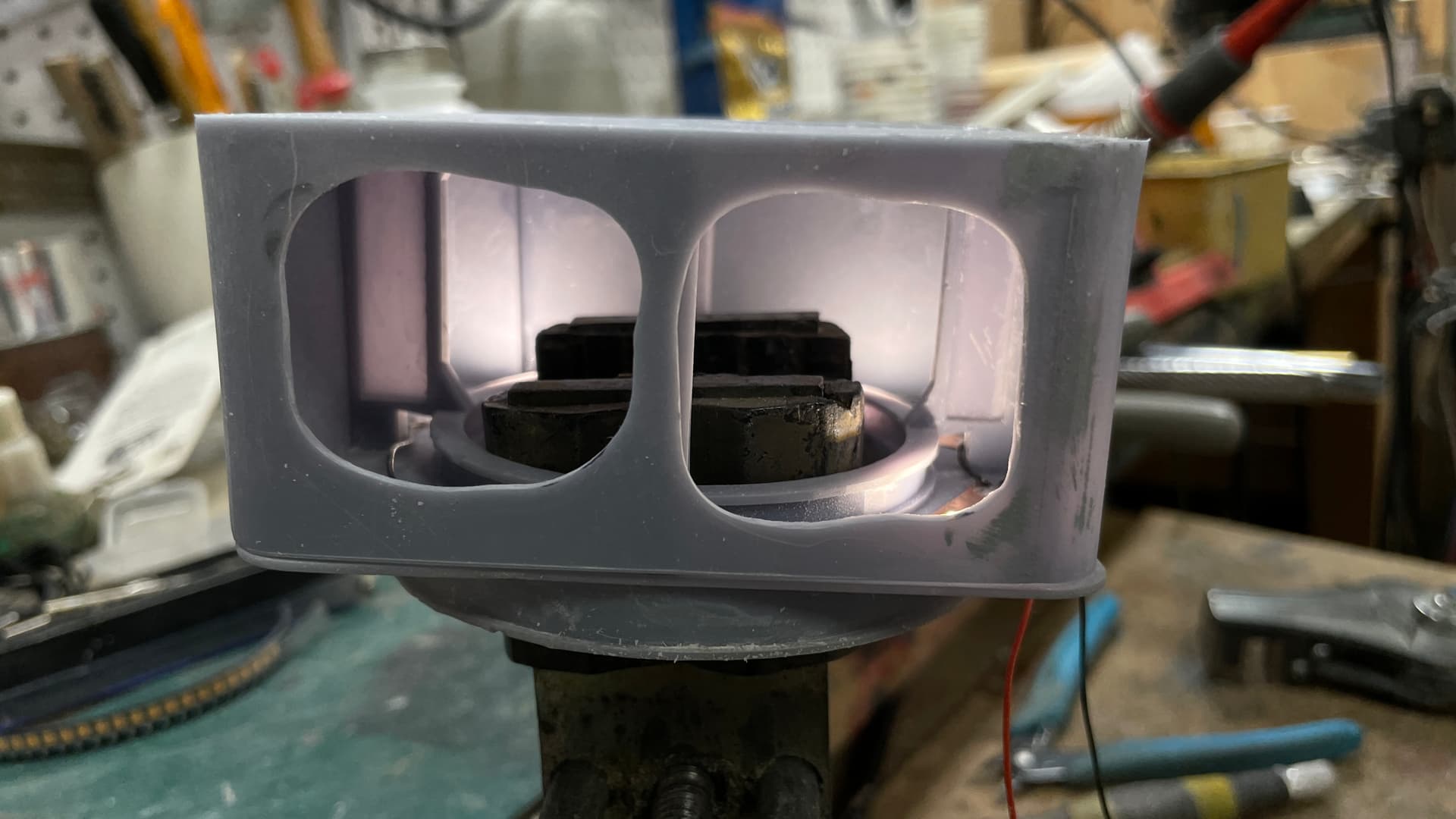
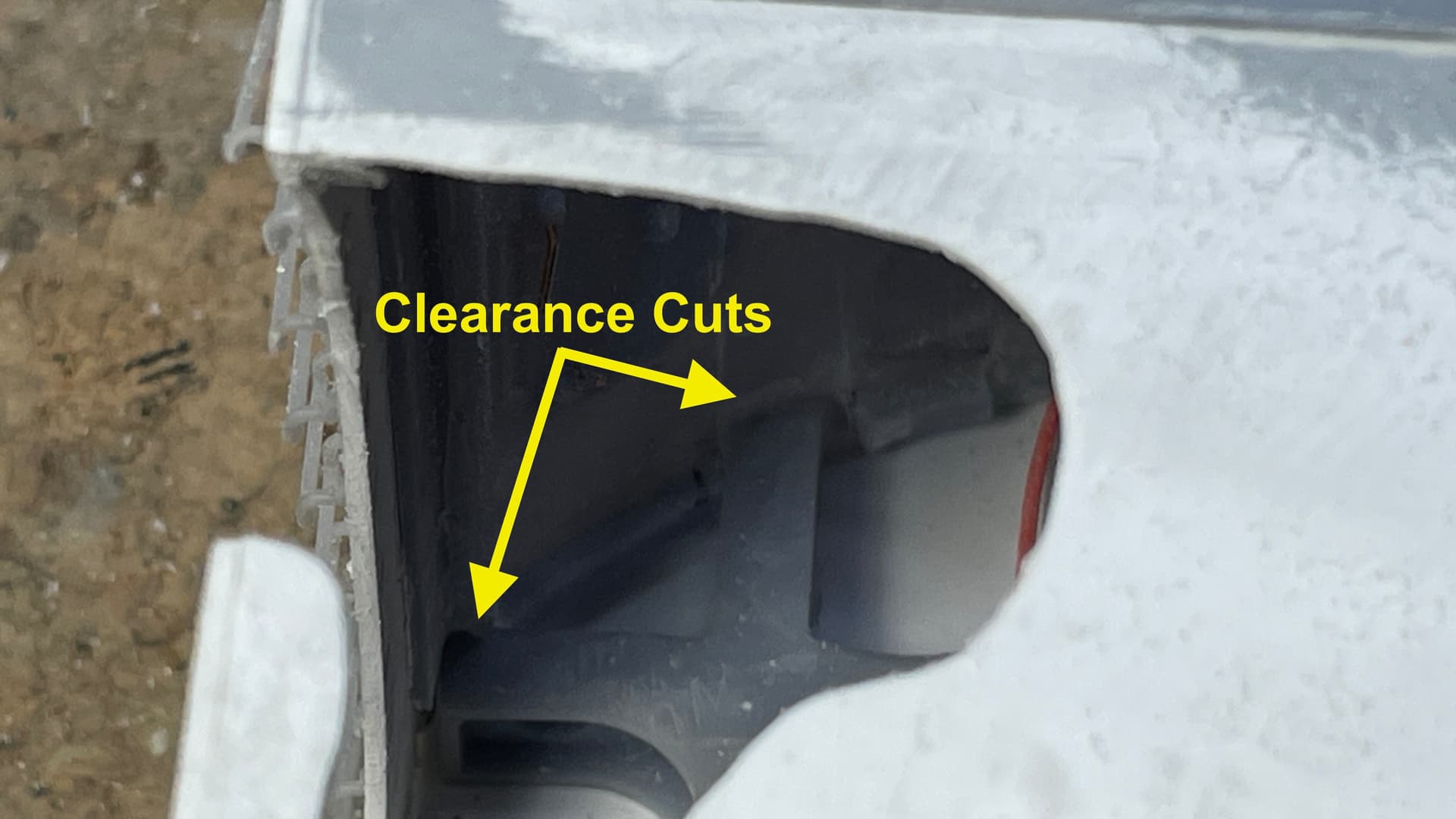
I wanted to test fit the GH on the frame and got some surprises. First I had to measure and cut off the telescope ends so I could slip the GH down over the lower part. I test fit the cutoff ends into the blisters on the GH side and they were too long and needed a little more trim to bring them flush with the inside wall. This is necessary so when assembled both parts look like they’re contiguous.
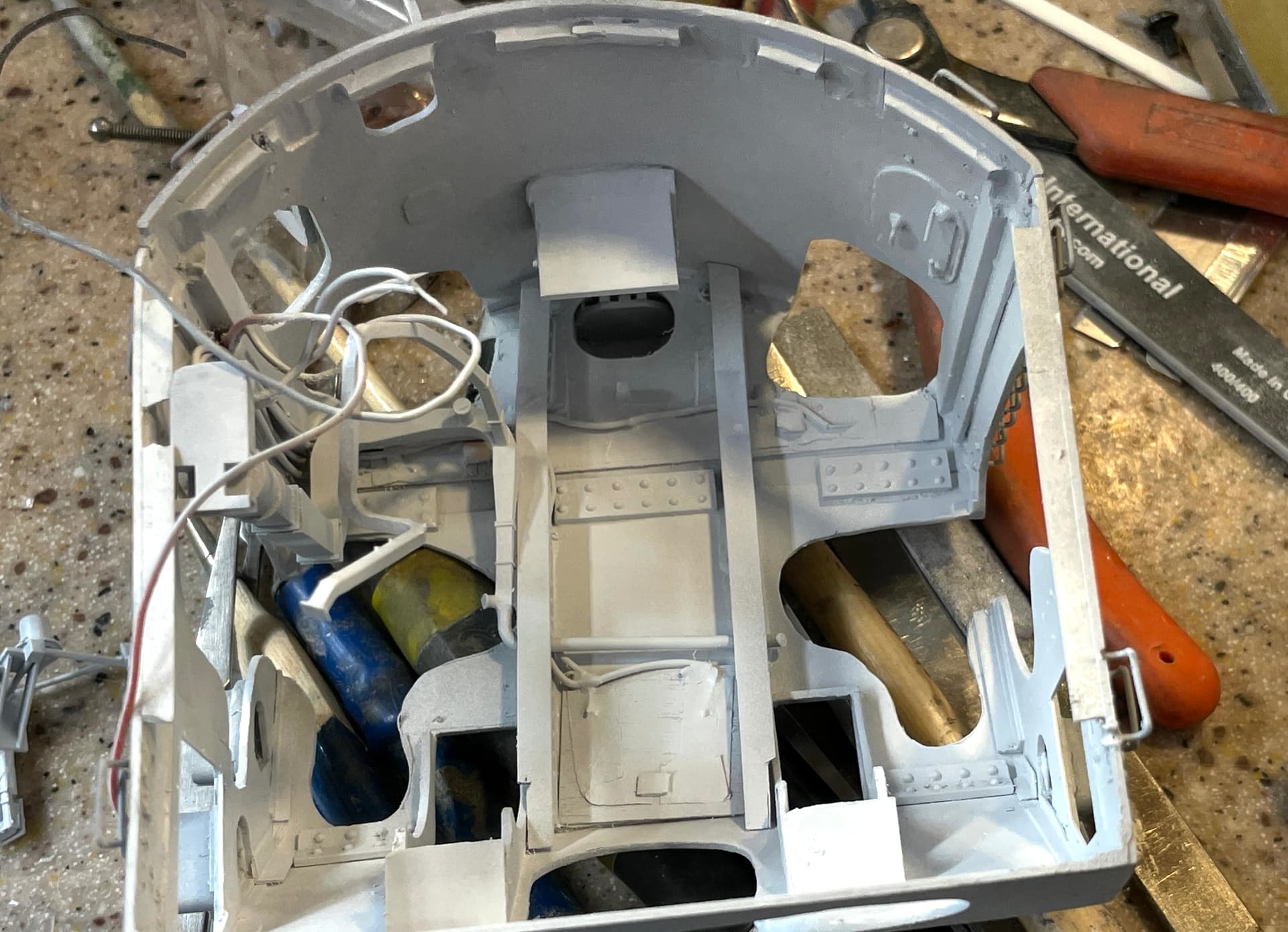
That wasn’t surprising since I could see on my drawings that the telescopes would prevent assembly and that they seemed too long. The surprise came when the frame impinged on the floor mount rib at the bottom. I either had to shorten the ribs or cut relief into the wall. I chose the latter, but this was delicated since I had to hold it while using the router. One slip and I would have been in a world of hurt. Even though I could reprint a new back wall, it was completely attached to the side walls, and filled. I was able to successfully make the cuts. There is a some trimming needed on the front piece where the corner angles are in the way, but that’s not as difficult as doing the rear wall.
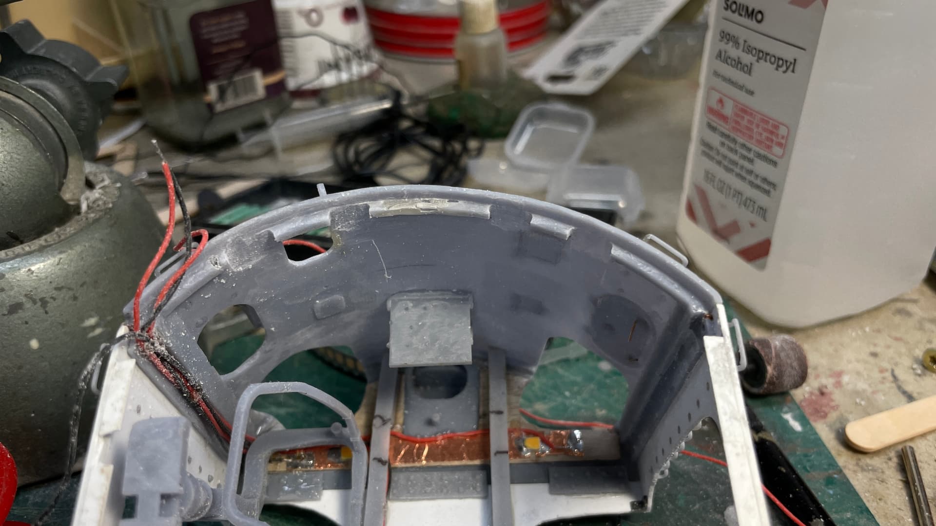
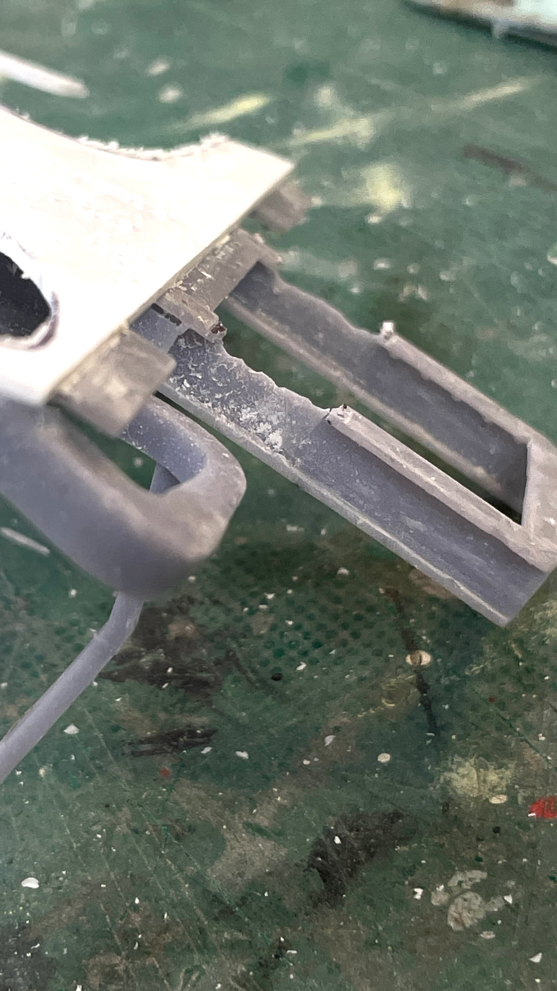
While a bit dark, you can see the interference. I’m not sure why I didn’t detect this during the design phase and draw the reliefs in. It would have been much more precise.
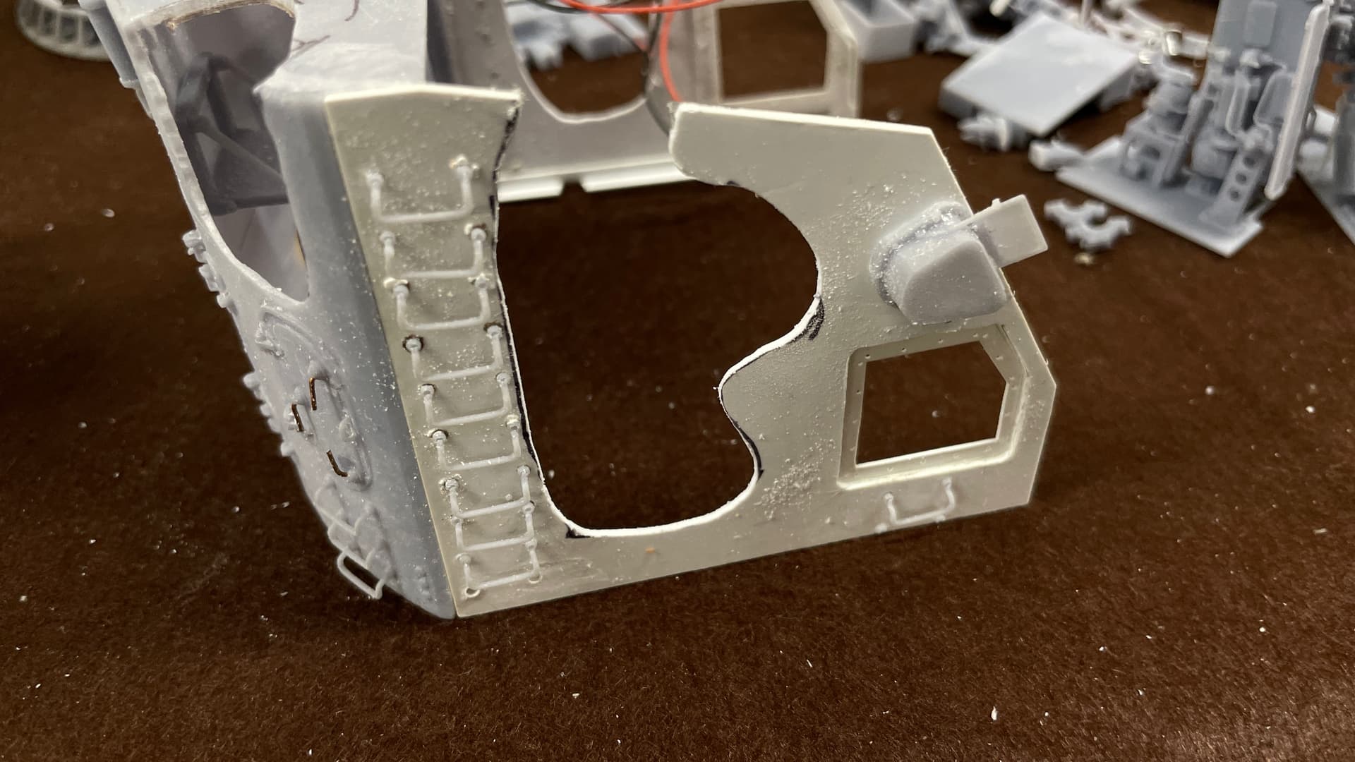
I took a picture with the work completed so far perched on the UHR. As I noted, there’s still some work that needs to be done. Right now the floor seems to want to sit below the gun house walls. I think it’s supposed to fit inside them.
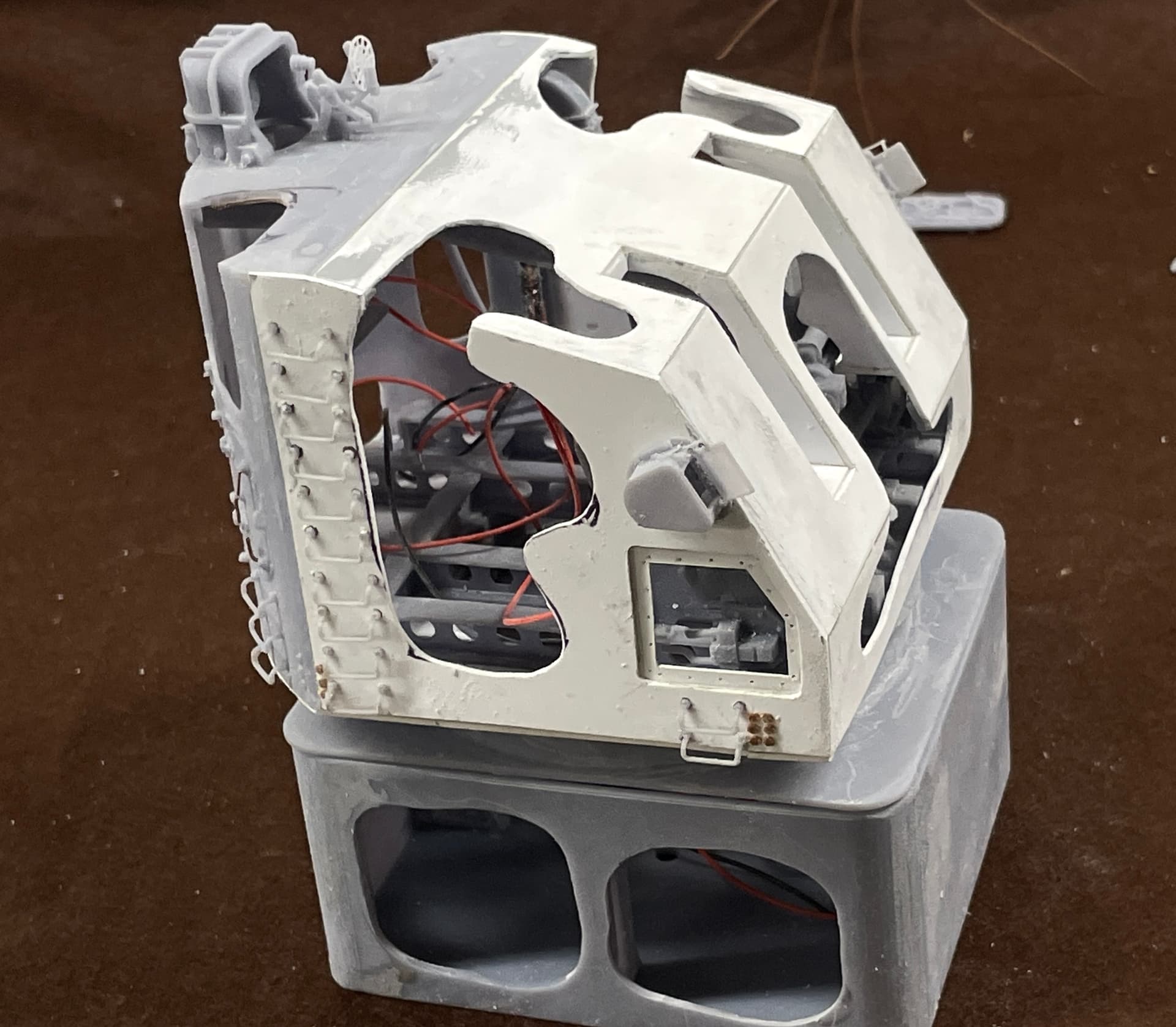
We’ll get there
9 Likes
Looking good … like the LEDs
Great progress Bill. Sorry to hear what your wife is going through. My wife went through that two years ago and it’s such a bummer. I hope her treatments are effective - if it helps, my wife sees the doc once every 6 months at this point and has 1 hormone prescription. Light at then end of the tunnel if you will.
1 Like
Thanks all. So far she’s doing pretty well and her last of four chemo infusions is in a week. We’re told it takes about a month after the last one for your body to start geting back to something like normal. Chemo wrecks a whole lotta stuff, most of which is reversible.
Painting is officially underway. Started on Monday when it was almost 80, and no wind so I could get outside to lay down the Tamiya solvent-based primer; white for the insides and gray for the rest. Yesterday after a full day to dry I airbrushed Tamiya gloss white for interior and a mixture of Tamiya of Gloss whilte an Flat Neutral Gray. I still have to paint the outsides with Life Color Haze Gray. After the white dried I started picking out the detials. This work still goes on. I’m reprinting a couple of parts for various reasons, and repaired a print defect on the ring frame/roof part.
Here’s the primed parts.
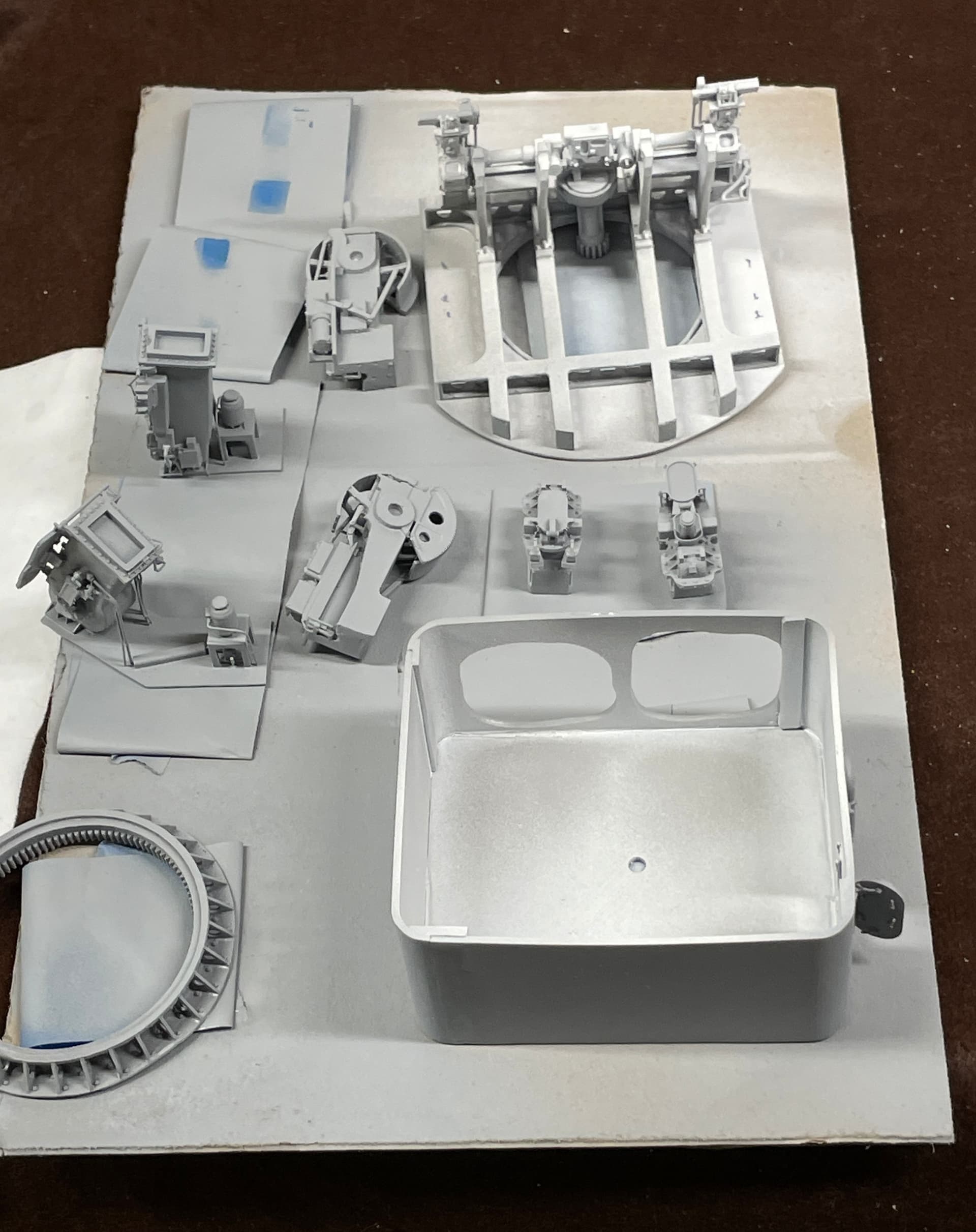
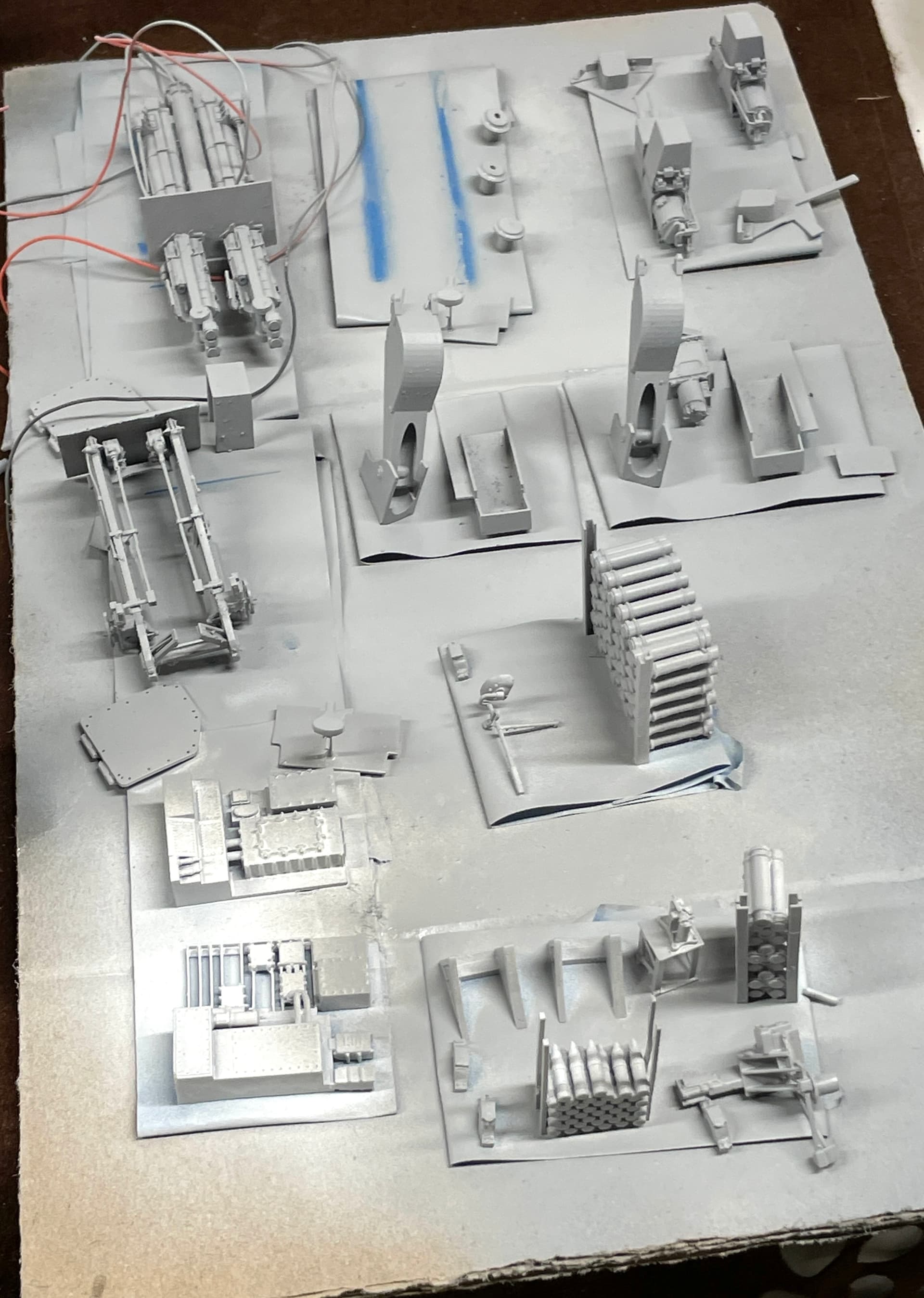
I love how the details pop with the primer on. Before painting I had reprinted a bunch of new ladder rungs and fixed all the broken ones.
The insides are now fully gloss white.
I will have to mask all the opennings from the inside to paint the haze gray on the outside. In the handling of the I broke ANOTHER bottom ladder rung. I’m thinking in my excellent 20/20 hindsight that I should have printed the ladder mounting lugs and made them out of bent wire. These things are driving me nuts and I don’t like how slopped up the work looks becuase of all the fussing.
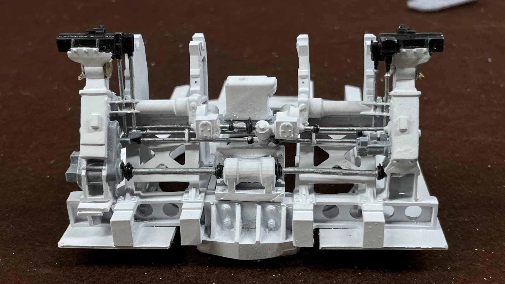
Detail painting started with the frame assembly. It’s a work in progress since there’s more to do.
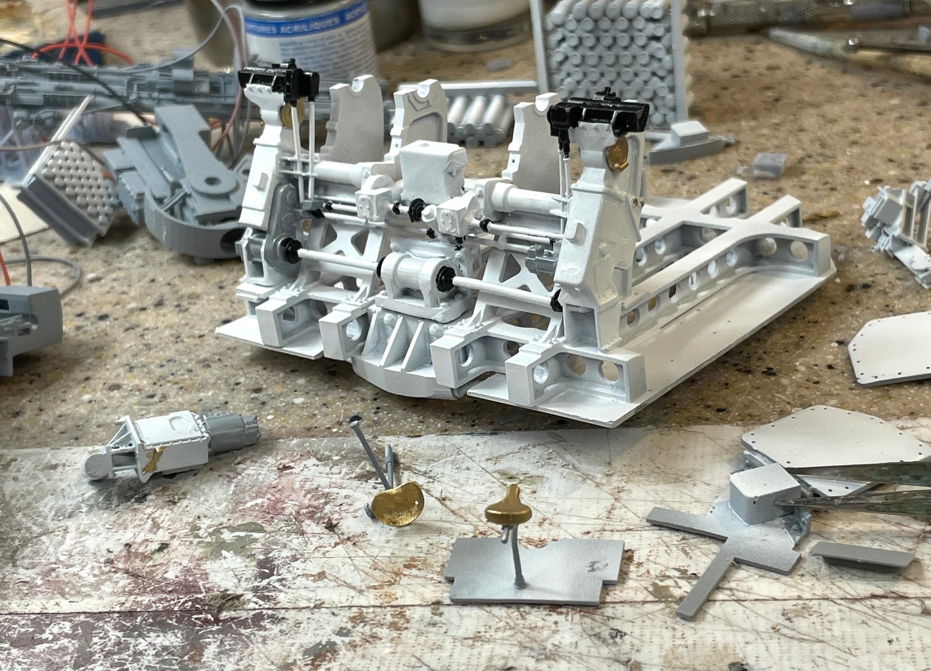
Today, I went back and overcoated all the rods with Dull Coat to seal the alcohol-based paint so I could paint it with Molotow Chrome paint which is also alcohol-based and would dissolve the white. I did the same on a lot of the gray parts that are going to get any metallic finishes.
I started painting the circuit panels for the UHR. These are not glued it. There’s a lot of bits that need to be picked out on these parts.
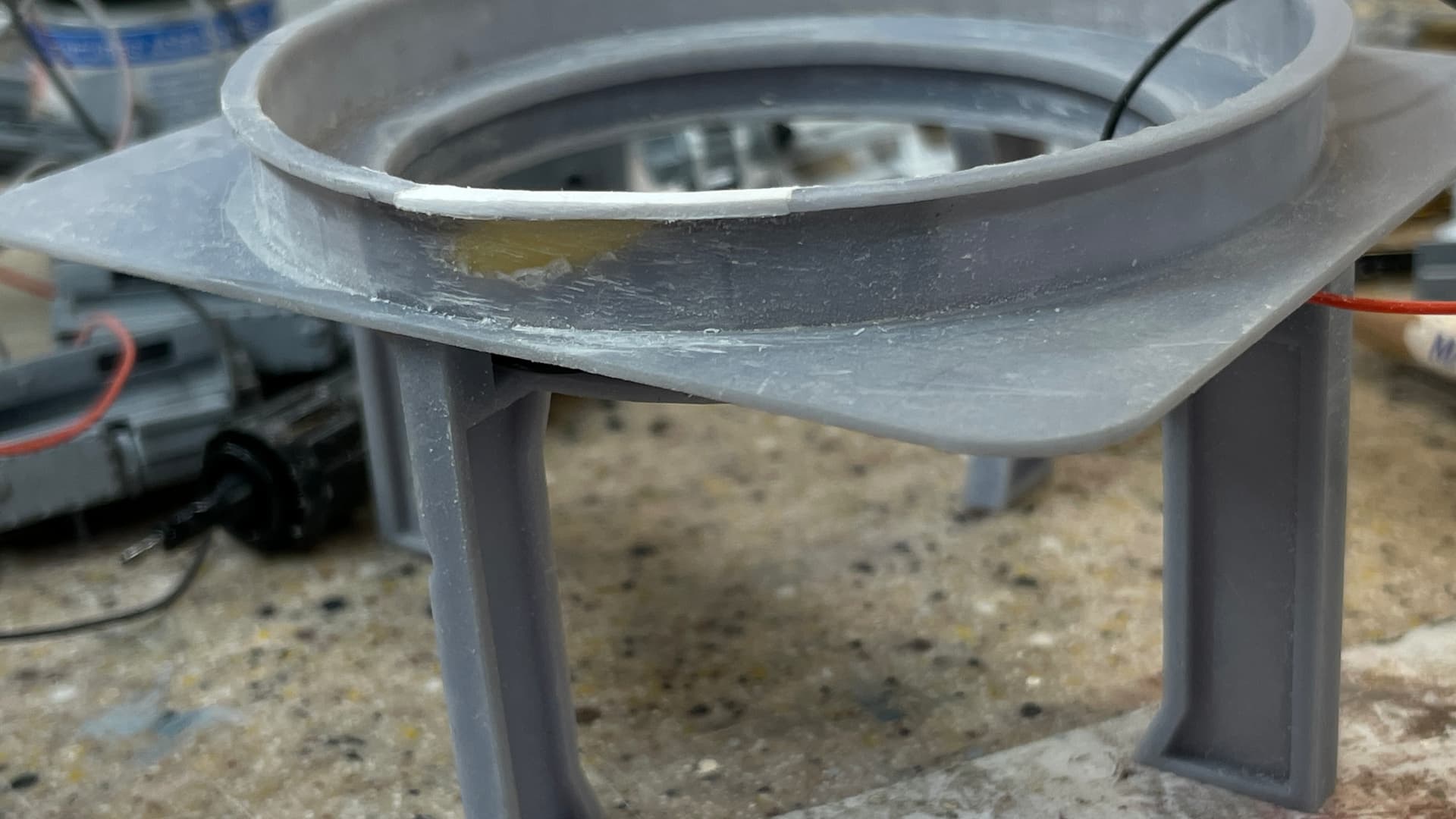
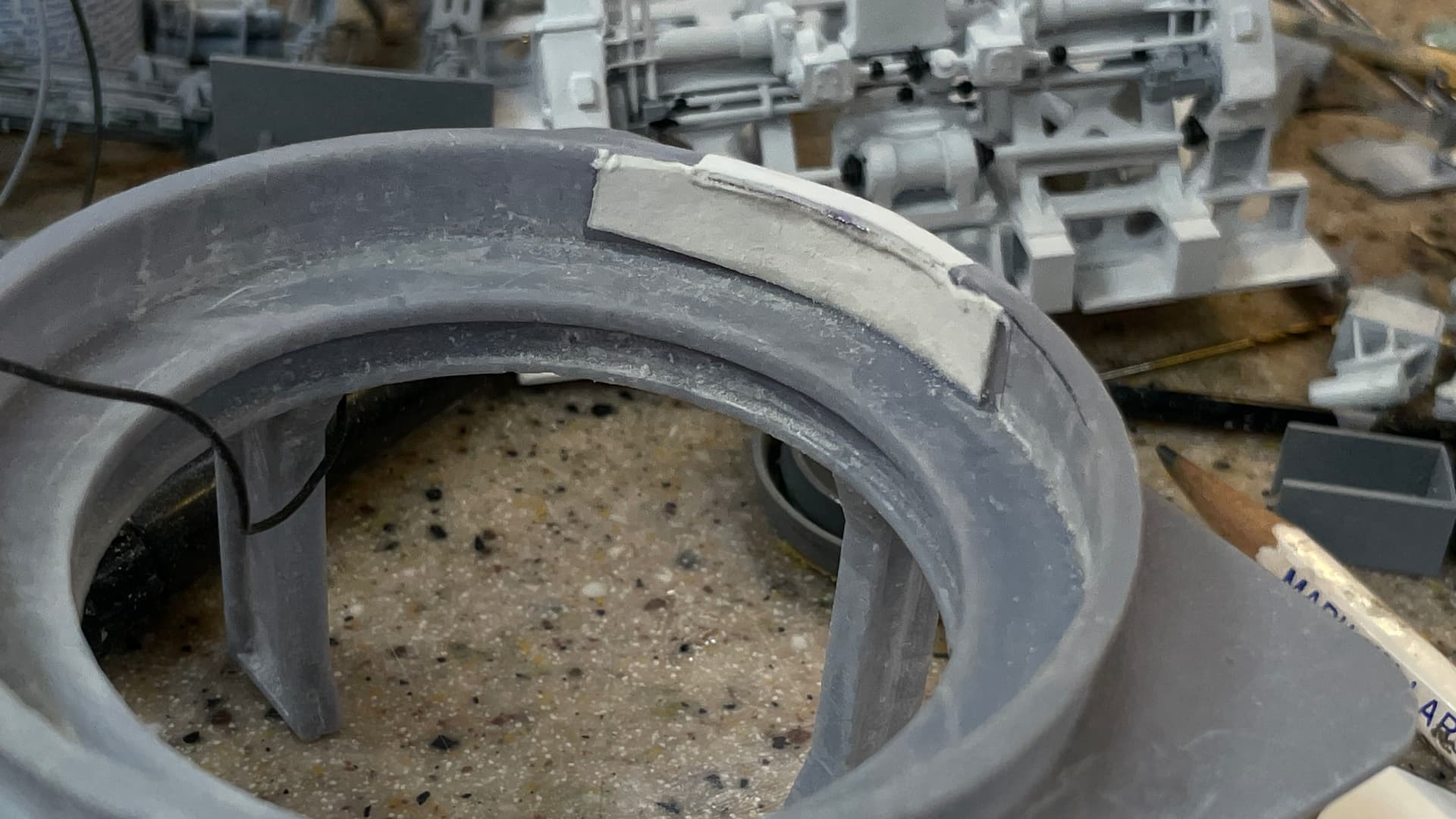
Today I fixed the print defect on the ring frame. I first trimmed the upper edge so a piece of shaped styrene would properly seat. I then put a piece of art paper as a backing held with CA and filled the broken area with Bondic. After sanding flush, and re-trimming the upper edge, I CA’d the rim piece in and finished sanded that. The repair will be undetectable. This rim will be cut away to expose for view the turret ring base and the training rack and pinion.
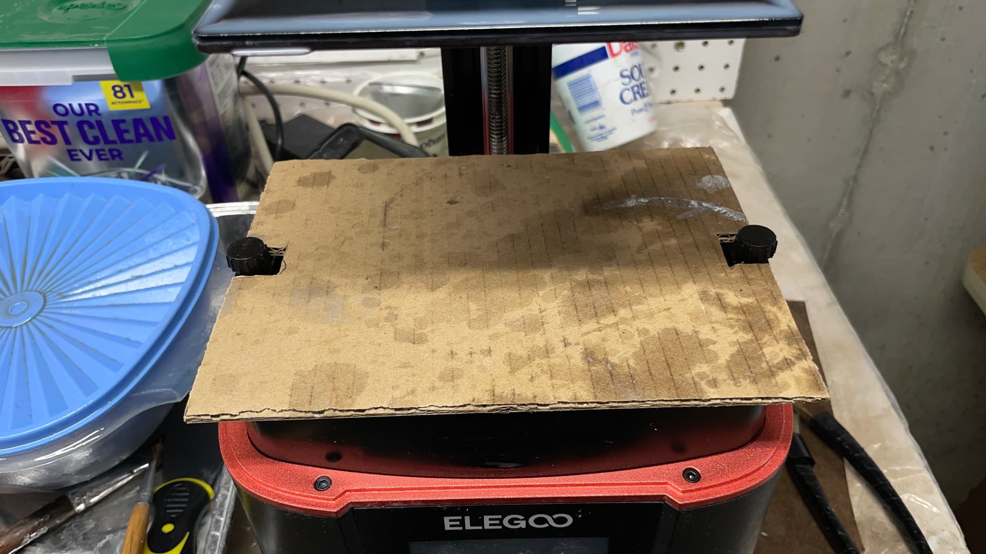
I also did something I should have done a long time ago. I made a resin vat protecter out of a piece of scrap cardboard. I’m using a spring built plate on my 3D printer that really saves time by letting you pop off the spring plate, bend it to remove the parts, clean it and then snap it back on. It’s held by a 3M magnetic backing. The problem arises when I try to align it before snapping it back on. Occasionally I loss grip of it just as I’m ready to snap it up and it heads into the resin vat. That’s no big deal. The big deal is when it goes in edge first and the edges are pretty thin. And this edge can penetrate the FEP and that is very bad. Now if it falls, it won’t do any damage.
8 Likes
Thanks all!
Short session today. First I want to share a sort of insidious 3D print failure. When I drew the upper dredge hoists for the upper handling room, I did two versions: open and closed storage lid. I drew the open one first and simply rotated the lid to the closed position for the other. That left a void in the part that, during printing, would fill with liquid resin that would not be exposed to UV to harden it. After curing, the lid warped and opened to release liquid resin all over the part.
To correct, I went back the drawing and closed the upper part to make it solid so the lid would be sitting on a closed space, thereby, not having a pocket of uncured resin to deal with. I just downloaded a new version of my slicer. As new versions go, it’s got some problems, but it does have a facility to test the object for voids. You can drill holes in the object in the slicer to open voids so the resin would drain, but in this case it was simpler to just redraw the part. I also correctly displayed the lid clamps in the clamped position.

I’m reprinting the corrected part now.
I had to completely disassemble and clean my Badger XF 150 airbrush. While I always shoot solvent through it after each use, occasionally I have to do a deep cleaning. That involves 15 minutes in the ultrasonic and a lot of fussing. Then I painted the white gloss on the undersides of the ring frame.
With Molotow Chrome paint I picked out the shafts in the sighting complex. I back painted white where necessary. It’s almost done. I don’t think I’m going to weather any of this, but I could be convinced otherwise.
Next session will continue detail painting.
8 Likes
Work continued yesterday on detail painting for the parts completed so far. I have to make some adjustments to my colors after re-checking my references. I was going on false memories of what is brass and what is paint. Today, I’m busy drawing the last gun house and UHR details: the communications and controls that are hanging on various places, including four columns that surround the gun captain’s position at the rear GH wall. Once I finish and print those I technically can assemble the gun house and upper handling room.
First, after correcting the UHR Dredge Hoist with the closed lid, I solved the leaking resin problem.
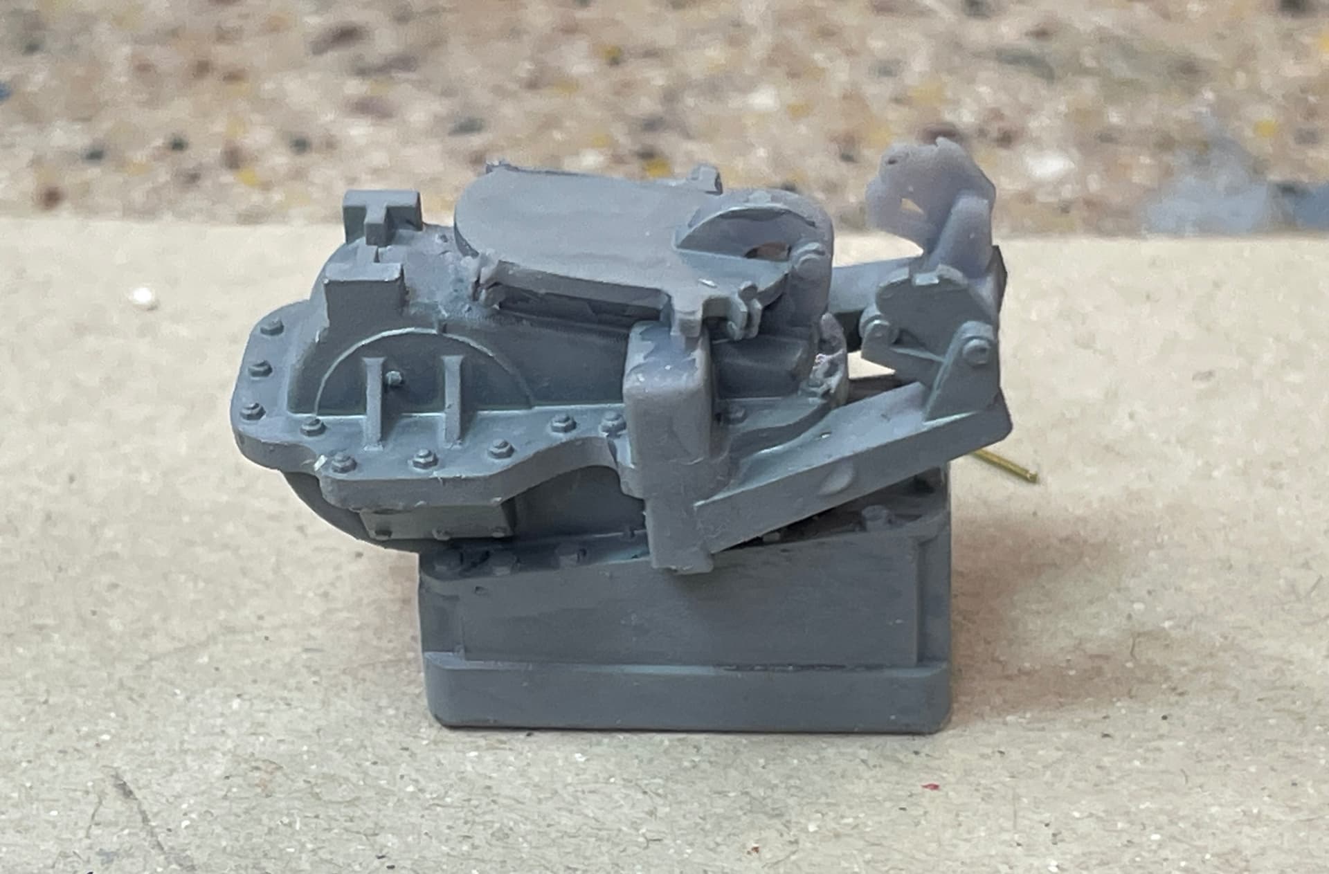
There are no details to paint on this part. It’s just all gray. I brush, rather than air brush painted this. It was still wet when I shot the pic.
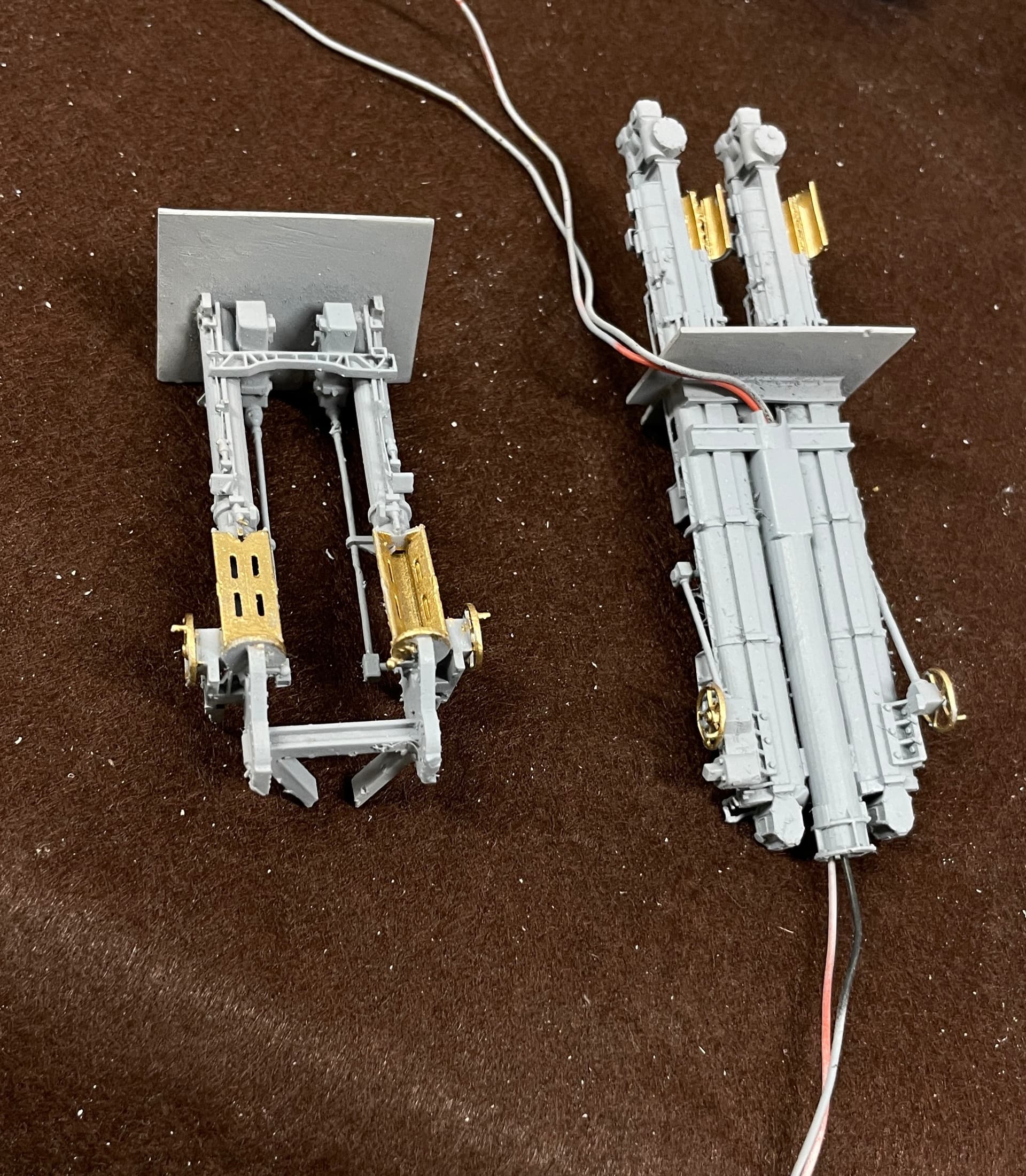
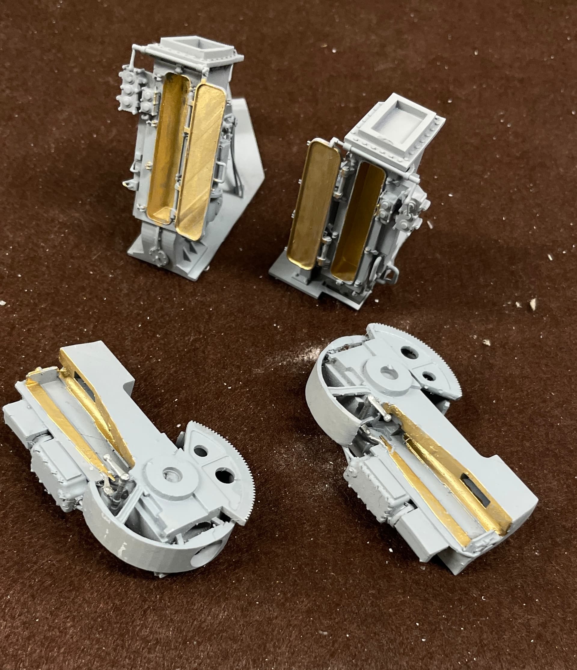
I painted the brass on the gun slides, open dredge hoist, projectile and powder hoists that go betweem GH and UHR, and the brass on the lower dredge hoists. I didn’t paint enough brass on the guns and too much on the lower hoists. The lids are not brass.
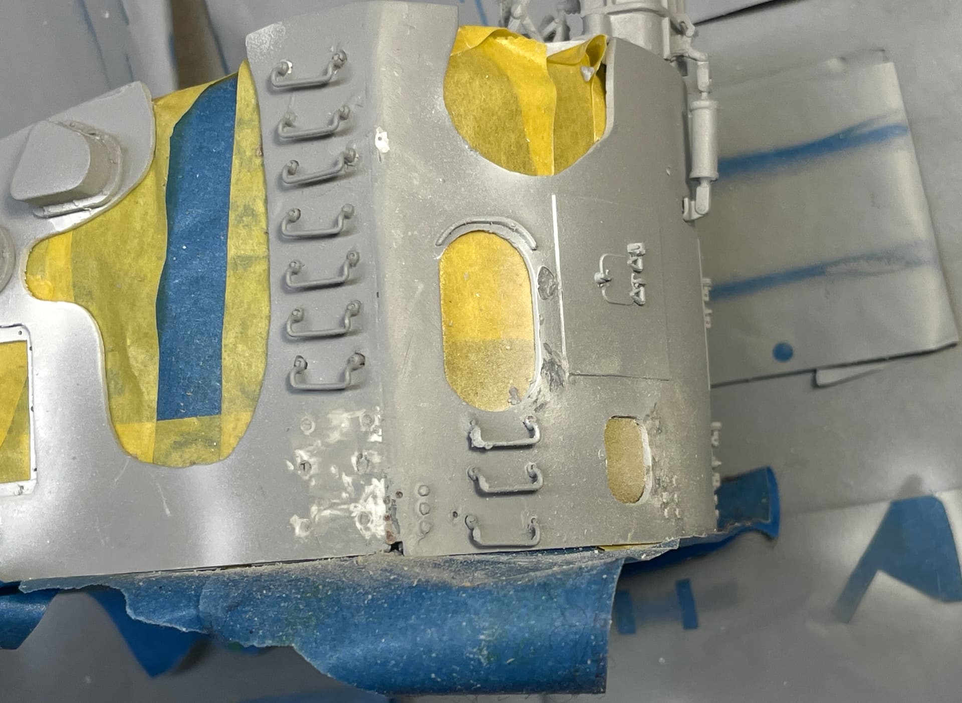
I then spent a lot of time masking the interior of GH and UHR. And, of course, I broke not only another foot rung, but beat the heck out of the two open gun house doors. I’m going to print new ones since the hinges are getting pretty munged up and re-gluing over and over is not working. The exterior gets painted WW2 Haze Gray. Current US Navy color is a lighter, more blue shade of gray. I’m doing WW2 configuration.
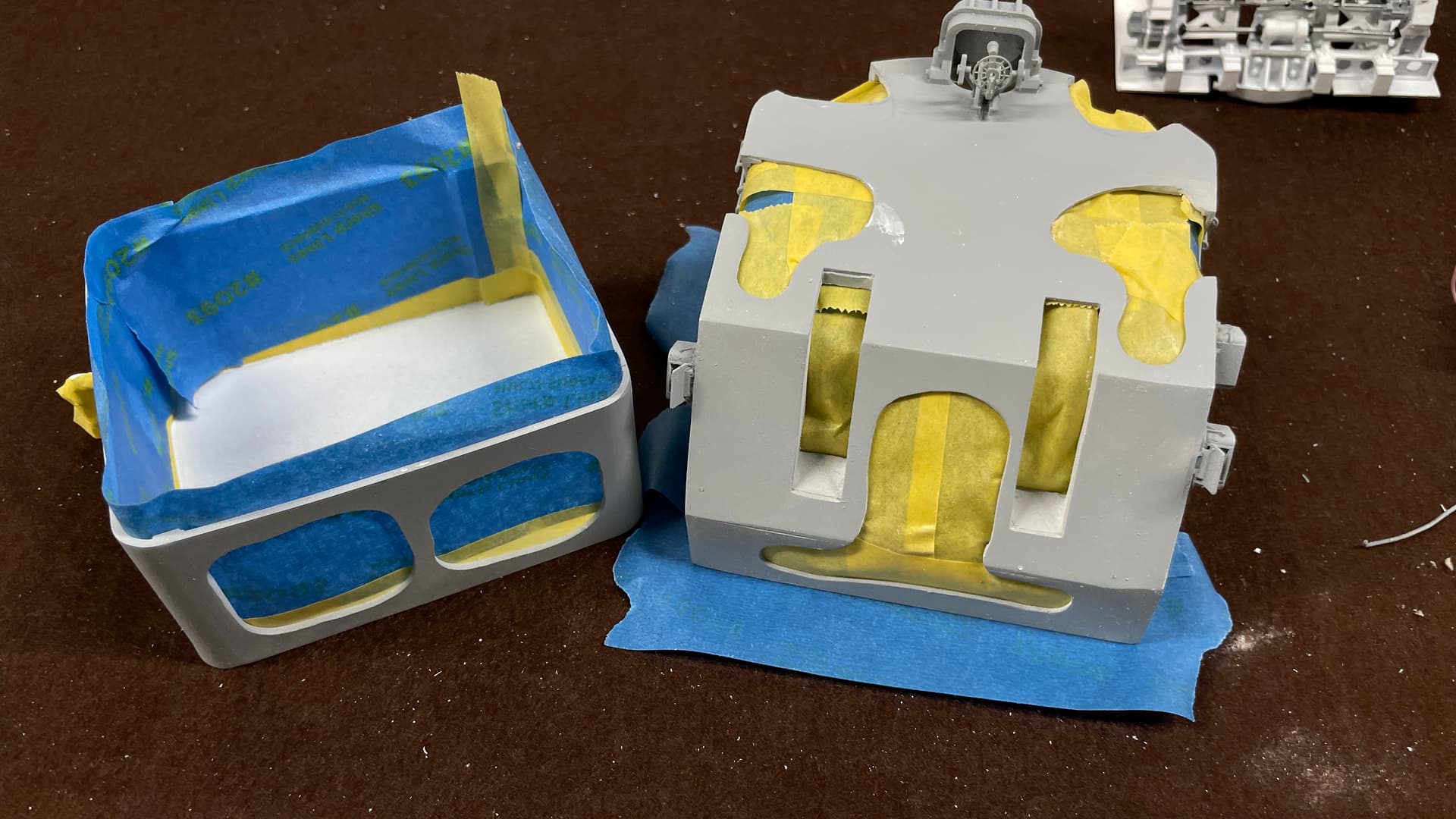
The problem is each time I turn the gun house to apply tape and apply some pressure I break something. I kind of knew this would happen.
7 Likes
Another pot pourri day…
I redrew the two open hatches on the gun house rear and made them open fully. I chose this position for two reasons; more solid purchase to drill and pin hinges to the wall, and having them not sticking out so far to keep from further breaking them during the rest of the assembly.
I then took the Dremel with tha diamond burr and removed all remnants of the previous door hinges (and broken foot rungs), so it’s ready to receive the newly printed doors.
I redrew the hoist hydraulics/gun captain’s perch to now include the controls and communications suite situated there. This was based on new and existing pictures from the Big J taken by Ryan.
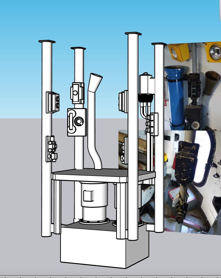
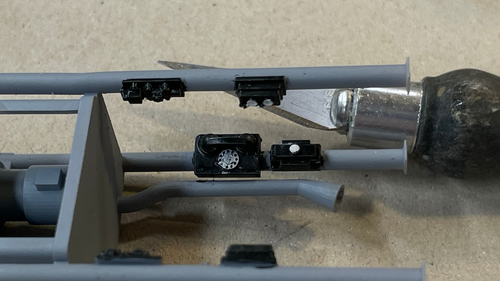
I drew the telephone dial and believe it of not, it fully printed including the finger stop.
I had to fit it into the gun house drawing to capture the height of the poles which seat under the roof girders. In the 1:1 ship, the rear poles are much smaller diameter than the front. I made them the same size for printablility.
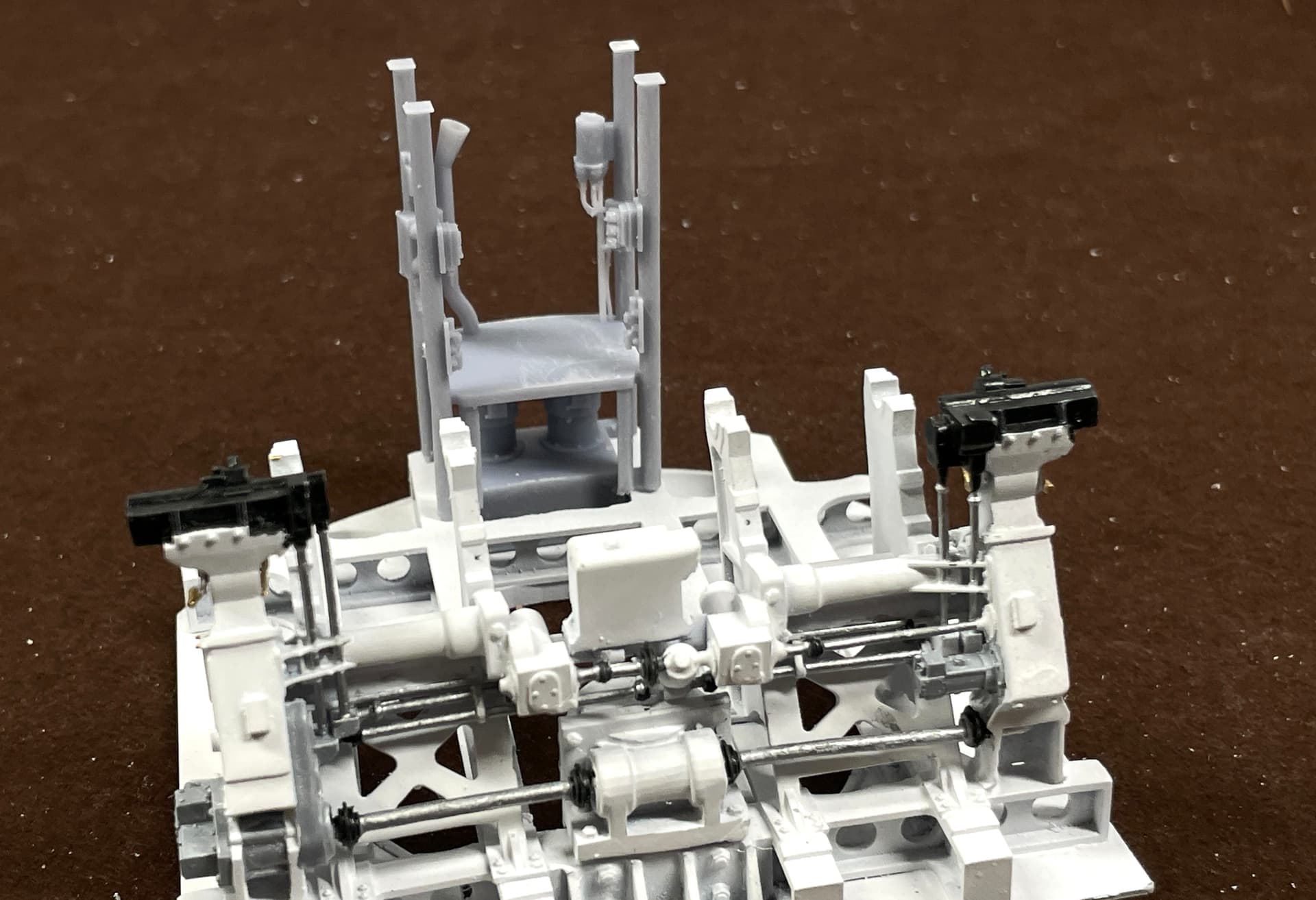
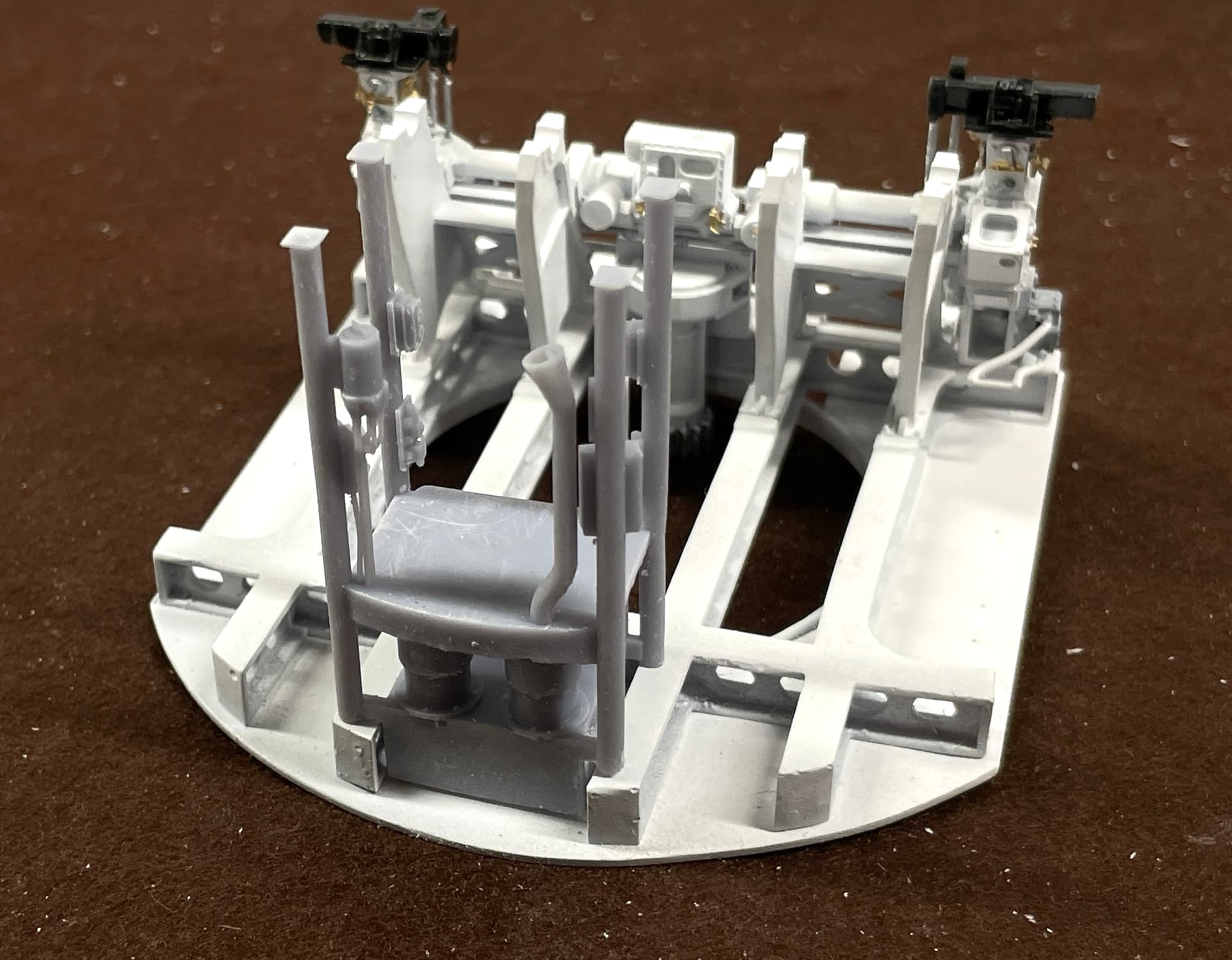
After painting the equipment, I took this shot. When I paint the phone dial, you will see that it’s actually there.
I also did some retouch painting on the guns and lower hoists. I reprinted one of the bicycle seats and painted it.
The guns had more brass than I originally painted it, and the front edge of the slide is gray not brass.
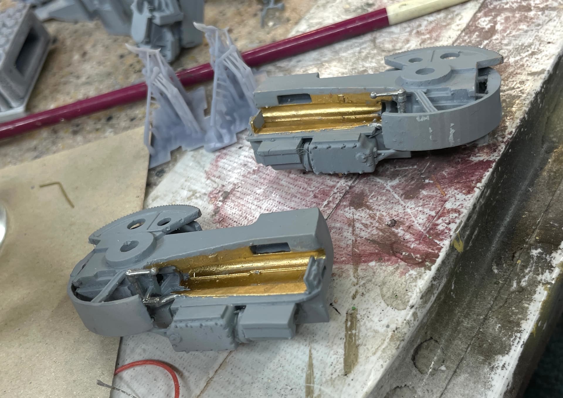
The open doors on the lower hoists are gray not brass, and I painted the control boxes. More details need to be done, but I just wanted to give a status.
My wife has her last Chemo tomorrow, so I may not get into the shop. Stay tuned.
8 Likes
Chemo is finished! The first days afterwards she still pumped full of steroids to tamp down the reaction plus anti-nausea meds. It will be Saturday before we can determine how well she’s doing with this last infusion. She’s getting better at it.
Ergo, not much time in the shop, but did get good prints on the replacement doors. BTW: you know I’ve harped on making multiple copies whenever I print. Yesterday was a prime example. The comms unit had one perfect print, and one non-existent one. The failed one separated from the build plate at some point and ended up as a blob on the FEP. This new film forumula by Elegoo is very forgiving. This one’s been on the machine for months, and it’s getting a big tired looking. I popped the chunk off, cleaned it with IPA and a micro-fiber cloth and put it back in service. I also gave the spring plate a quick abrasive hit with 400 grit emery. Next print… perfect. No delamination.
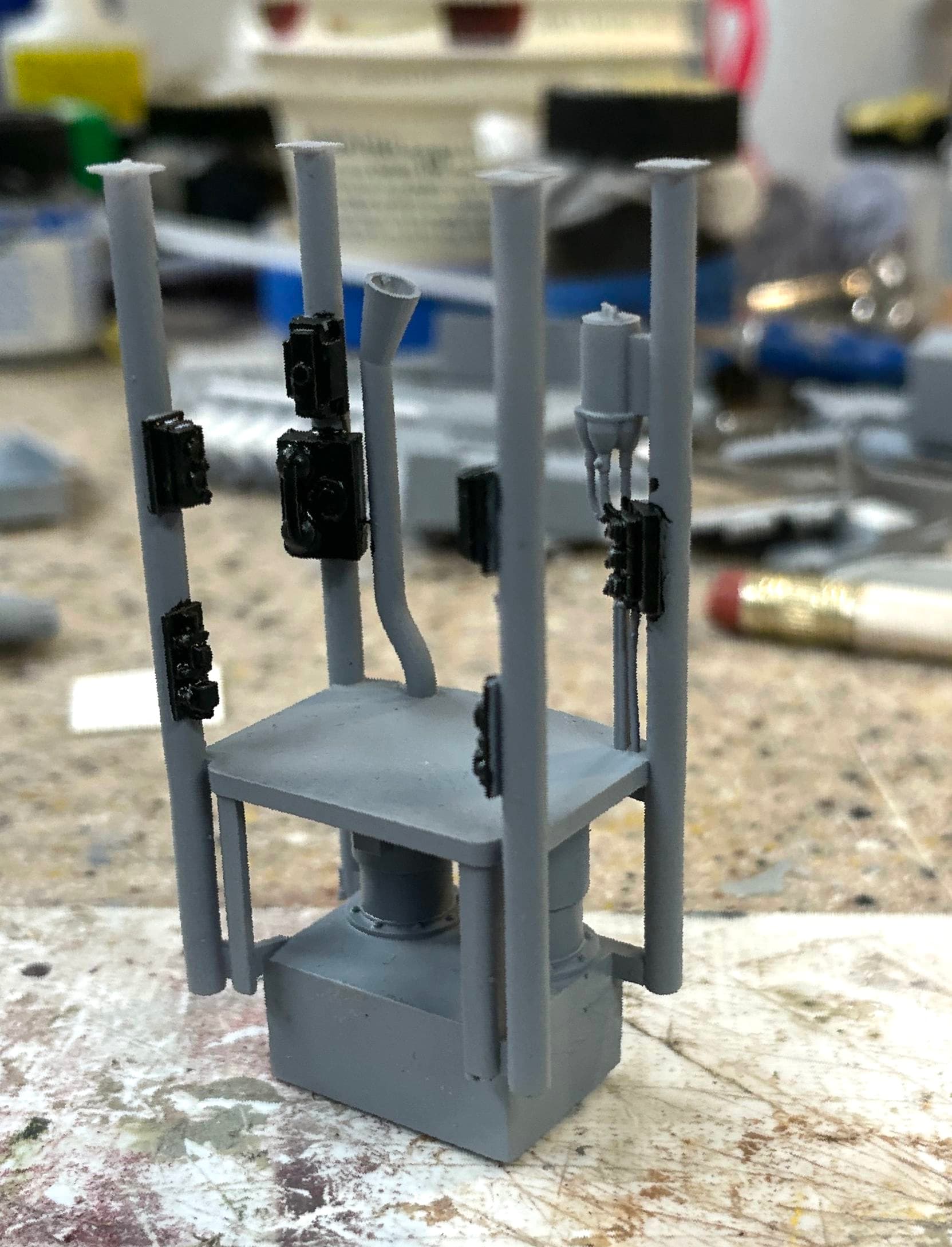
I painted the details on the comms units and you can now see the very minute telephone dial. I draw in SU at 100X full size since it doesn’t like drawing small circles and curves when the segments go below a certain threshhold. There’s a trick. You first make the 1:1 part a component. In SU, when you copy a component, anything you do to one instantly gets done to the others. And it allows you to scale the object as long as you don’t change it in any way. So you copy the 1:1 object when you first start to draw it. Up scale the copy some large amount. You don’t need to worry about the actual scale you choose becasue after you do all the work on the giganitic one, you delete it leaving the 1:1 object with all the changes and work you did on the big one. Now this is a mystery… How does it let you make small curves on the original as a componet copy of the big one, but doesn’t let you work with tiny curves on the origninal in the first place. No one has explained this to me. I don’t really care. It works.
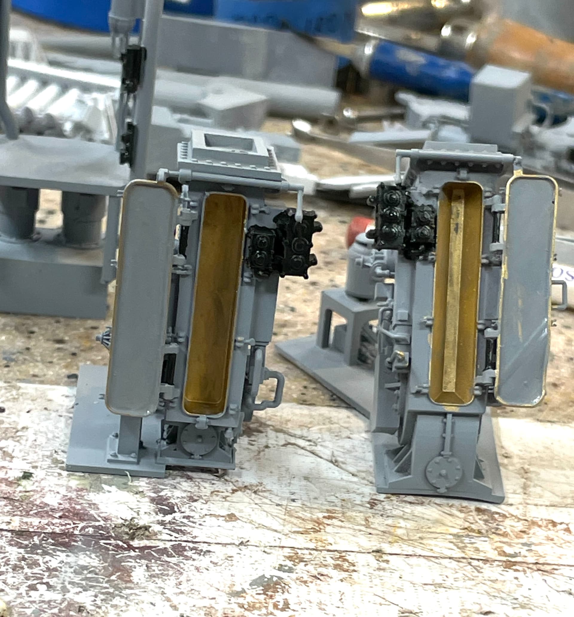
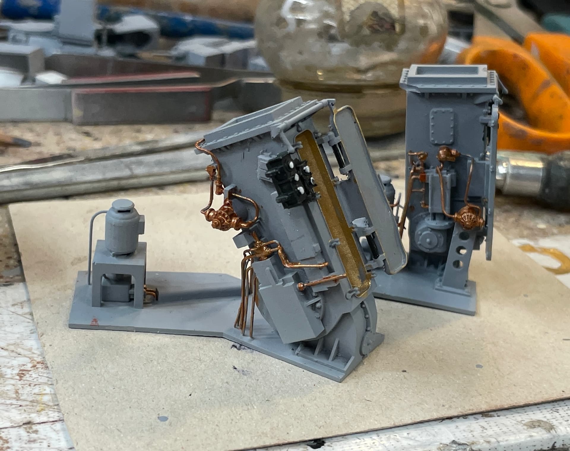
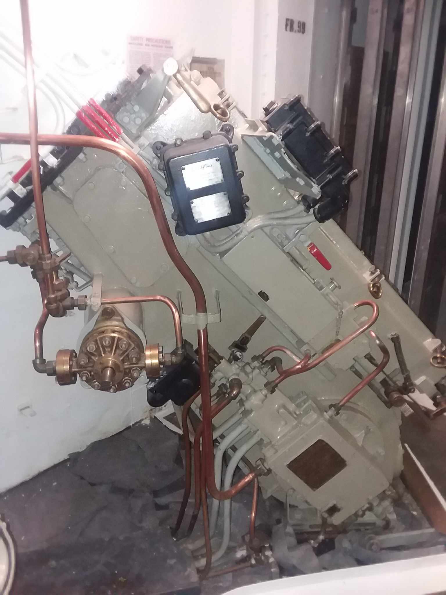
I did more detail painting on the lower hoists. With the copper piping added, it starts to look pretty good. Still need to go back and add some weathering to highlight the contours. Naval equipment wouldn’t be alllowed to get too dirty. A chief petty officer wouldn’t allow it.
Here’s the original photo for comparison.
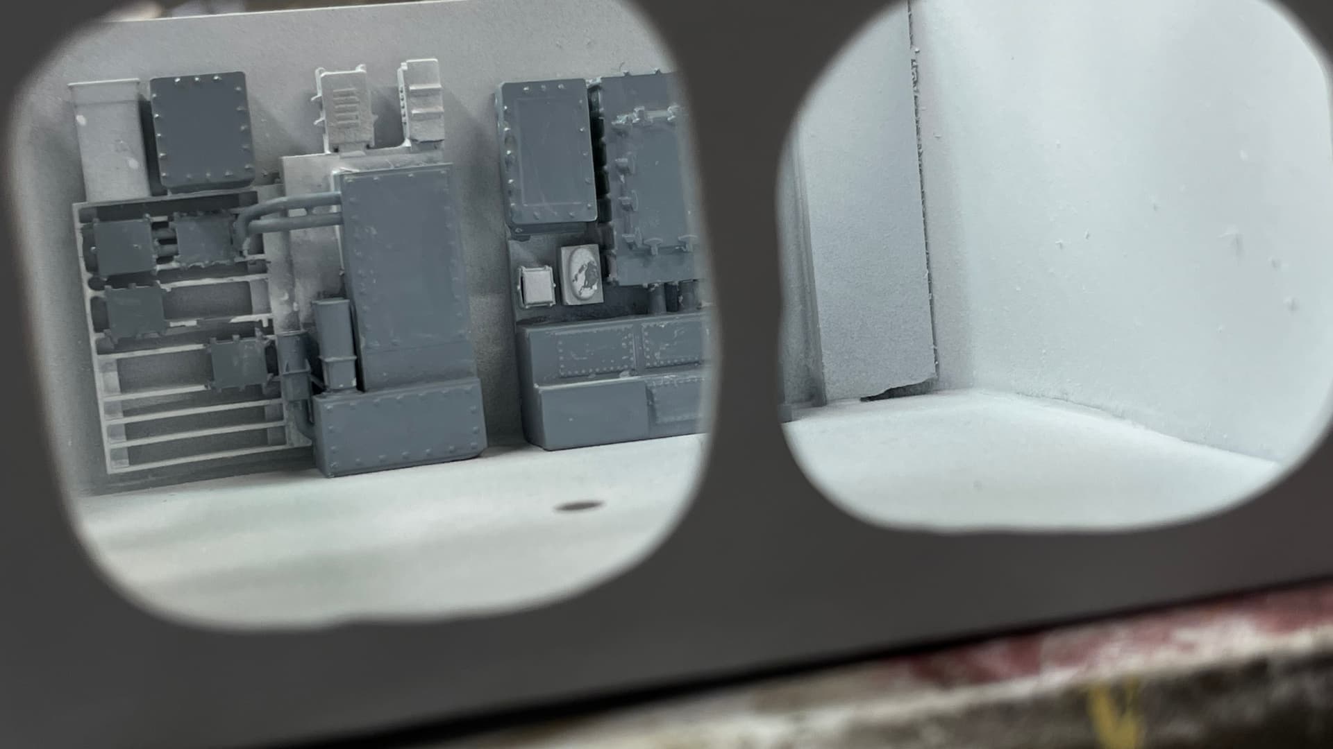
I told Ryan that, even with all the holes cut in the gun house shield, it would still be nearly impossible to see what’s going on inside. There’s just too many vision blocks. That’s essenitally the reason that I will need to supplement the model with the electronic image dispaly showing the parts outside of of the model or in stages of completion with dialog and callouts to show what’s what.
With the interior lighting it will help, but as you can see, you can barely see the comm equipment mounted on those poles in the rear.
7 Likes
Best of luck to your wife’s recovery Myles
4 Likes